Embed Size (px)
Citation preview

Hydrodynamic Design of Francis Turbine Runner
P M V SubbaraoProfessor
Mechanical Engineering Department
Provision of Features to Efficient & Benign Muscle.…

Environment Friendly Runner
• The issue of safe fish passage dominating the decision of whether a new generation turbine design concept is environmentally friendly.
• Fish passage is an important issue to many hydroelectric plants’ operations.
• Biological design criteria are needed to assist in establishing allowable limits of hydraulic parameters that may contribute to fish mortality and plant operation.
• Injury and mortality mechanisms are dependent on the zone which the fish takes to pass through the turbine system.
• At Wanapum Dam in Washington, fish that passed through a zone near the turbine hub experienced 5% higher mortality than fish that passed through the zone in the middle of the runner.

• Injuries caused by pressure appear to be related to the difference between the acclimation pressure upstream of the turbine and the exit pressure within the draft tube zone.
• A threshold value of the shear stress indicator was identified as 135 m/s/m.
• Values above this rate are believed to cause mortality .
• Turbines can be designed to operate cavitation free while increasing power production. Proper turbine operation at cavitation-free conditions will reduce maintenance costs and fish mortality that is believed to be related to cavitation.
• Tests at Wanapum Dam showed that peak fish survival did not coincide with peak efficiency

Fish Injury Mechanisms

Fish Friendly Runner
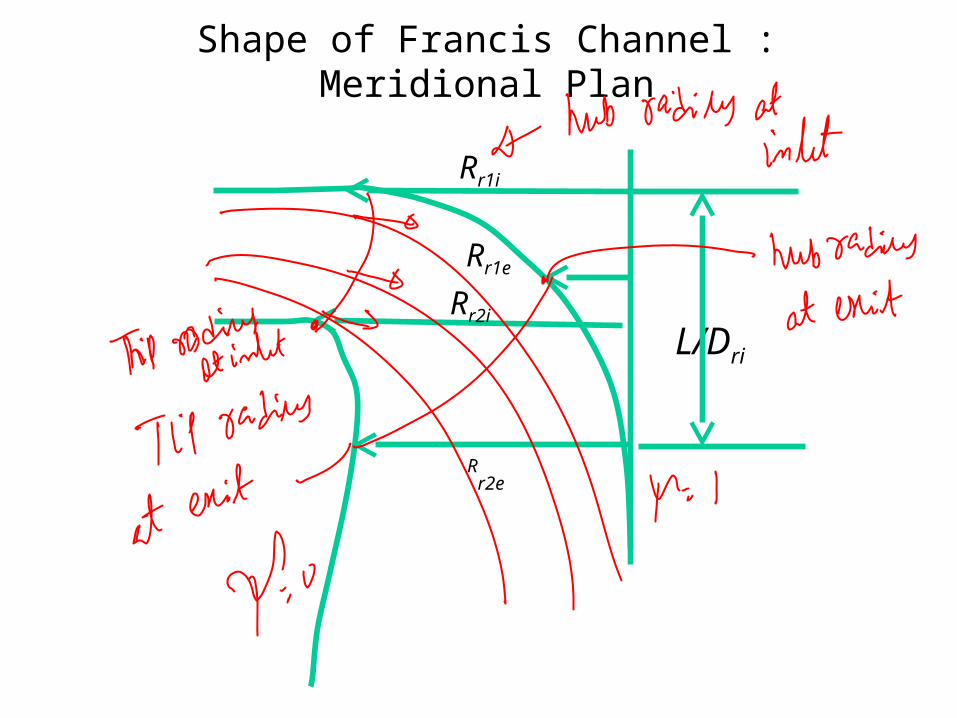
Shape of Francis Channel : Meridional Plan
Rr1i
Rr2e
L/DriRr2i
Rr1e

Real values of Radii
The real value of the outlet tip radius3
1
22
eer
QR
The real value of the intlet root radius3
1
21
1
2
iir h
gHR
28.024.0 2 e 8.165.1 1 ih
Rr2e and Rr1i are only fix two points of the leading and trailing edges and the rest of these curves should be drawn to lead to better efficiency of runner.

Determination of Inlet & exit edges runner
1i
2i
1e
2e
The form of these edges is two parabolic curves.
Define the non-dimensional specific speed
Q
gH
NN NDs 75.0260
2
For 275.0088.0 NDsN
the leading edge form is a parabolic arcwith the peak in the point by radius of 2.Rr1i-Rr2iwhich passes through the points 1i and 2i,

1i
2i
1e
2e
and for specific speeds between
its form is also a parabolic arc but with the minimum point in the 1iand the axis is parallel to runner axis.
89.0275.0 NDsN
In the exit area, trailing edge is a parabolic curve which has a minimum point in 1e and also passes through a point such as 2i with a radius of Rr1i/3.

Dimensions of Runner Channel : Meridional Plan
•The BOVET well known relations give the geometry of hub and shroud curves in the runner blade zone. •The form of limit curves is defined by equation:
L
z
L
z
L
z
R
R
m
1108.3
Rr1i
Rr2e
L/DriRr2i
Rr1e

Location of Runner Vane in Runner Channel

Variation of Flow Velocity
Vf
s
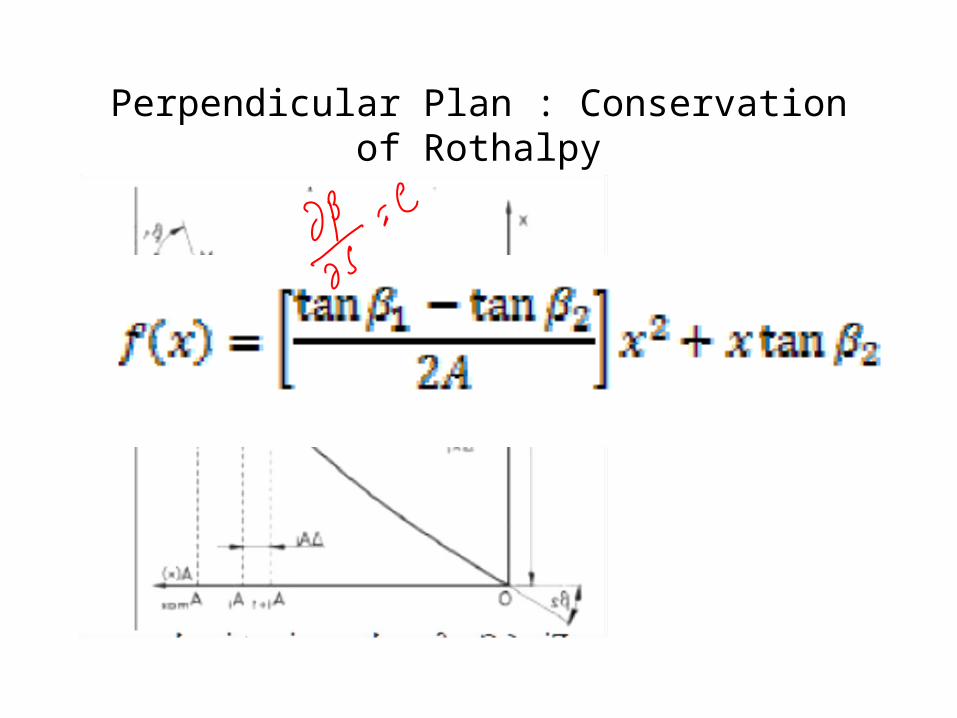
Perpendicular Plan : Conservation of Rothalpy