Embed Size (px)
Citation preview

1Revision date: 12.12.19
*Actual system may differ from what is shown.
115822 Commercial NFT System for a 30’ x 48’ Greenhouse115823 Commercial NFT System for a 30’ x 60’ Greenhouse115824 Commercial NFT System for a 30’ x 72’ Greenhouse115825 Commercial NFT System for a 30’ x 84’ Greenhouse115826 Commercial NFT System for a 30’ x 96’ Greenhouse115827 Commercial NFT System for a 30’ x 132’ Greenhouse
©2019All Rights Reserved. Reproduction is prohibited without permission.
Designed to grow healthy plants without soil using mineral-nutrient solutions.
HydroCycle Commercial NFT Systems
2 115822_23_24_25_26_27 Revision date: 12.12.19
REQUIRED TOOLS
The following list identifies the main tools needed to assemble the hydroponic system. Additional tools and supports may be needed.
• Tape measure, marker, and chalk line
• Variable speed drill (cordless with extra batteries works best)
• Socket and ratchet set and wrench set that includes 1/2" and 9/16"
• Hammer and gloves
• Level (2'– recommended) and line levels
• Utility knife and carpenter's square
• Adjustable pliers and assorted hand tools common to plumbing and electrical work
• Step drill bit or bits to drill 3/8" and 1-3/8" holes.
• 3" and 5" hole saw bits.
• Drill bit — 9/32"
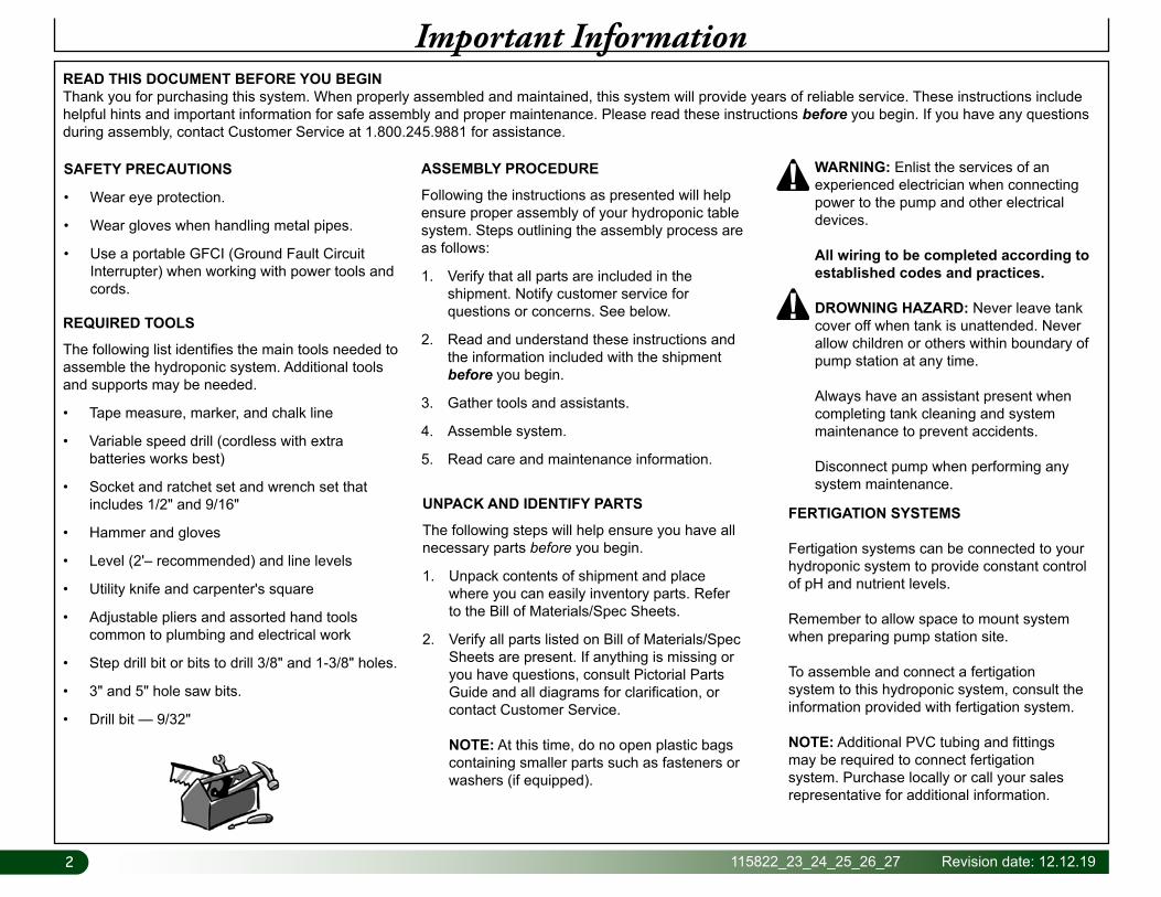
READ THIS DOCUMENT BEFORE YOU BEGINThank you for purchasing this system. When properly assembled and maintained, this system will provide years of reliable service. These instructions include helpful hints and important information for safe assembly and proper maintenance. Please read these instructions before you begin. If you have any questions during assembly, contact Customer Service at 1.800.245.9881 for assistance.
ASSEMBLY PROCEDURE
Following the instructions as presented will help ensure proper assembly of your hydroponic table system. Steps outlining the assembly process are as follows:
1. Verify that all parts are included in the shipment. Notify customer service for questions or concerns. See below.
2. Read and understand these instructions and the information included with the shipment before you begin.
3. Gather tools and assistants.
4. Assemble system.
5. Read care and maintenance information.
Important Information
SAFETY PRECAUTIONS
• Wear eye protection.
• Wear gloves when handling metal pipes.
• Use a portable GFCI (Ground Fault Circuit Interrupter) when working with power tools and cords.
UNPACK AND IDENTIFY PARTS
The following steps will help ensure you have all necessary parts before you begin.
1. Unpack contents of shipment and place where you can easily inventory parts. Refer to the Bill of Materials/Spec Sheets.
2. Verify all parts listed on Bill of Materials/Spec Sheets are present. If anything is missing or you have questions, consult Pictorial Parts Guide and all diagrams for clarification, or contact Customer Service.
NOTE: At this time, do no open plastic bags containing smaller parts such as fasteners or washers (if equipped).
WARNING: Enlist the services of an experienced electrician when connecting power to the pump and other electrical devices.
All wiring to be completed according to established codes and practices.
DROWNING HAZARD: Never leave tank cover off when tank is unattended. Never allow children or others within boundary of pump station at any time.
Always have an assistant present when completing tank cleaning and system maintenance to prevent accidents.
Disconnect pump when performing any system maintenance.
FERTIGATION SYSTEMS
Fertigation systems can be connected to your hydroponic system to provide constant control of pH and nutrient levels.
Remember to allow space to mount system when preparing pump station site.
To assemble and connect a fertigation system to this hydroponic system, consult the information provided with fertigation system.
NOTE: Additional PVC tubing and fittings may be required to connect fertigation system. Purchase locally or call your sales representative for additional information.
3Revision date: 12.12.19 115822_23_24_25_26_27
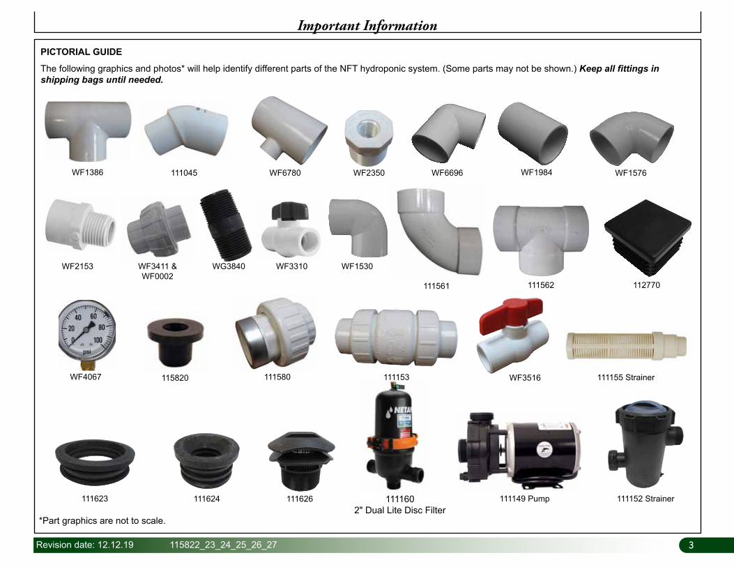
1111602" Dual Lite Disc Filter
Important Information
PICTORIAL GUIDE
The following graphics and photos* will help identify different parts of the NFT hydroponic system. (Some parts may not be shown.) Keep all fittings in shipping bags until needed.
WF1386 111045 WF6780 WF2350 WF1984 WF1576
111561
WF6696
WF2153 WF3411 & WF0002
WF1530
111562
WF3310WG3840
WF4067 115820 WF3516111580 111155 Strainer111153
111623 111624 111626 111149 Pump 111152 Strainer
*Part graphics are not to scale.
112770
4 115822_23_24_25_26_27 Revision date: 12.12.19
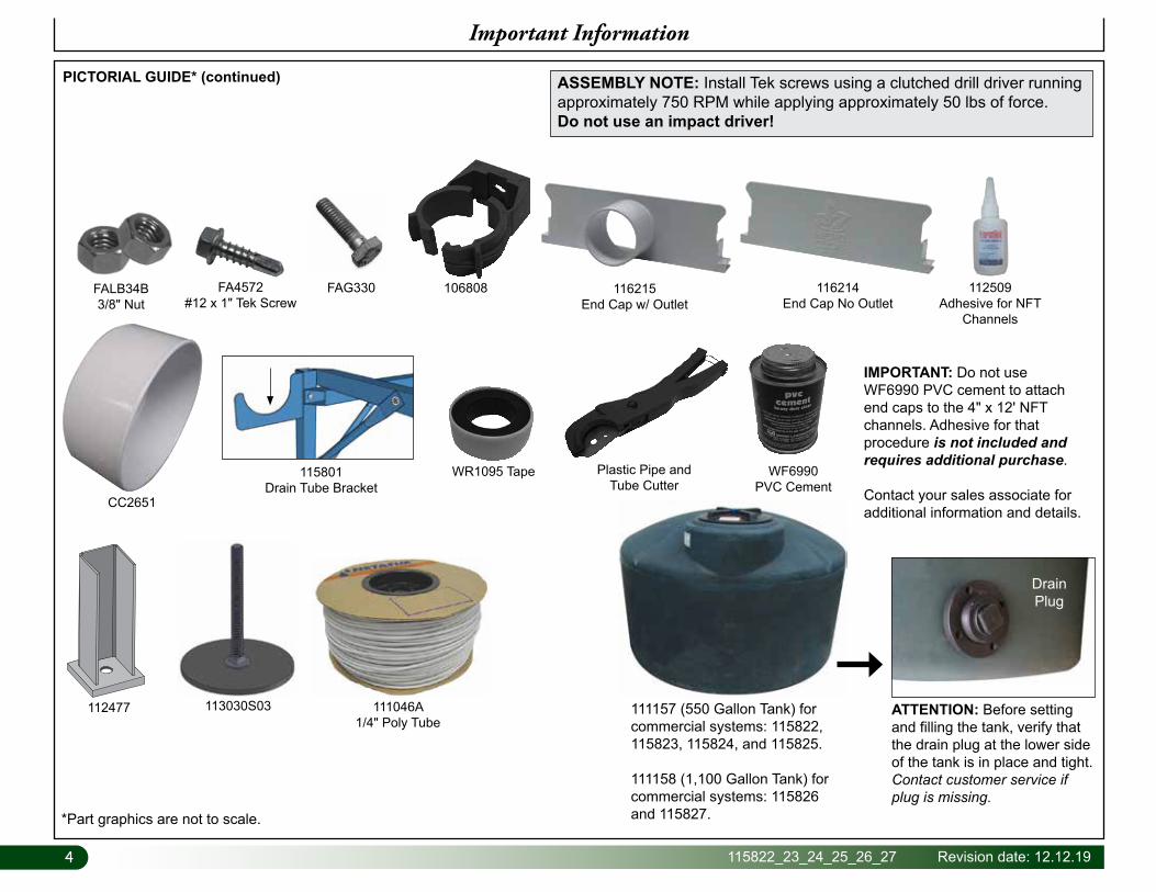
PICTORIAL GUIDE* (continued)
Important Information
WR1095 Tape WF6990PVC Cement
Plastic Pipe and Tube Cutter
IMPORTANT: Do not use WF6990 PVC cement to attach end caps to the 4" x 12' NFT channels. Adhesive for that procedure is not included and requires additional purchase.
Contact your sales associate for additional information and details.
ATTENTION: Before setting and filling the tank, verify that the drain plug at the lower side of the tank is in place and tight. Contact customer service if plug is missing.
Drain Plug
111157 (550 Gallon Tank) for commercial systems: 115822, 115823, 115824, and 115825.
111158 (1,100 Gallon Tank) for commercial systems: 115826 and 115827.
111046A1/4" Poly Tube
106808
CC2651
FALB34B3/8" Nut
FA4572#12 x 1" Tek Screw
113030S03112477
FAG330
*Part graphics are not to scale.
115801Drain Tube Bracket
ASSEMBLY NOTE: Install Tek screws using a clutched drill driver running approximately 750 RPM while applying approximately 50 lbs of force. Do not use an impact driver!
112509Adhesive for NFT
Channels
116215End Cap w/ Outlet
116214End Cap No Outlet
5Revision date: 12.12.19 115822_23_24_25_26_27
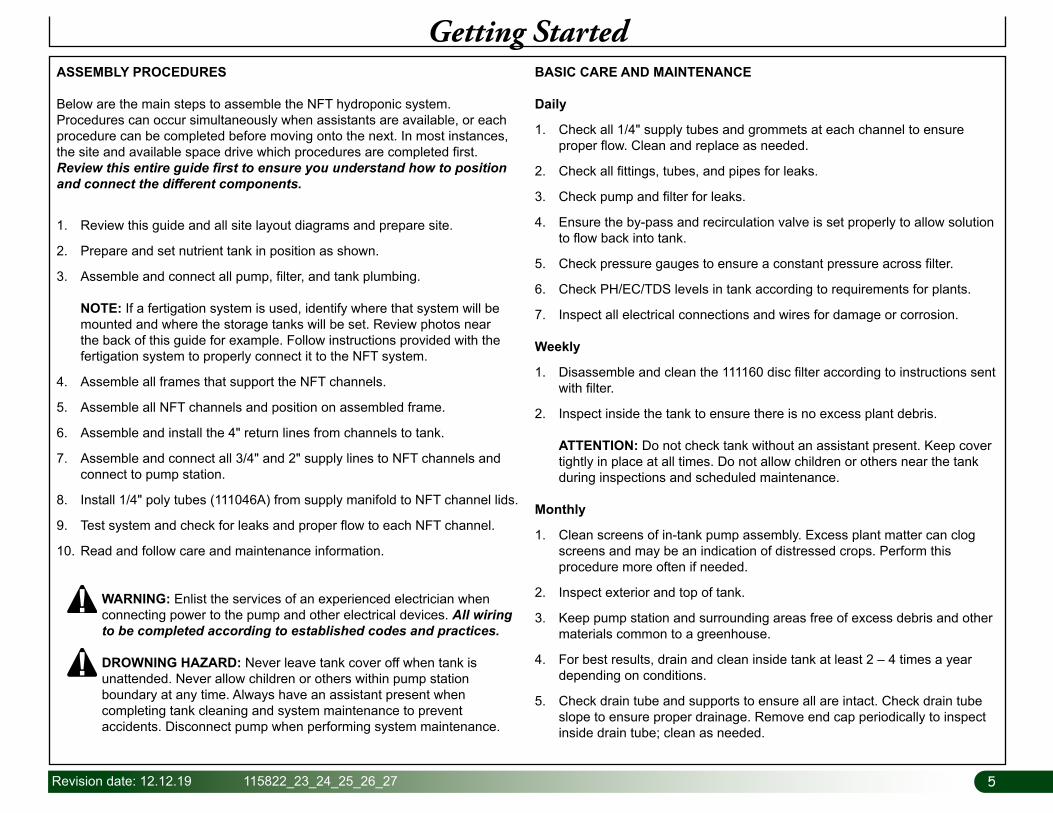
Getting StartedASSEMBLY PROCEDURES
Below are the main steps to assemble the NFT hydroponic system. Procedures can occur simultaneously when assistants are available, or each procedure can be completed before moving onto the next. In most instances, the site and available space drive which procedures are completed first. Review this entire guide first to ensure you understand how to position and connect the different components.
1. Review this guide and all site layout diagrams and prepare site.
2. Prepare and set nutrient tank in position as shown.
3. Assemble and connect all pump, filter, and tank plumbing. NOTE: If a fertigation system is used, identify where that system will be mounted and where the storage tanks will be set. Review photos near the back of this guide for example. Follow instructions provided with the fertigation system to properly connect it to the NFT system.
4. Assemble all frames that support the NFT channels.
5. Assemble all NFT channels and position on assembled frame.
6. Assemble and install the 4" return lines from channels to tank.
7. Assemble and connect all 3/4" and 2" supply lines to NFT channels and connect to pump station.
8. Install 1/4" poly tubes (111046A) from supply manifold to NFT channel lids.
9. Test system and check for leaks and proper flow to each NFT channel.
10. Read and follow care and maintenance information.
BASIC CARE AND MAINTENANCE
Daily
1. Check all 1/4" supply tubes and grommets at each channel to ensure proper flow. Clean and replace as needed.
2. Check all fittings, tubes, and pipes for leaks.
3. Check pump and filter for leaks.
4. Ensure the by-pass and recirculation valve is set properly to allow solution to flow back into tank.
5. Check pressure gauges to ensure a constant pressure across filter.
6. Check PH/EC/TDS levels in tank according to requirements for plants.
7. Inspect all electrical connections and wires for damage or corrosion.
Weekly
1. Disassemble and clean the 111160 disc filter according to instructions sent with filter.
2. Inspect inside the tank to ensure there is no excess plant debris. ATTENTION: Do not check tank without an assistant present. Keep cover tightly in place at all times. Do not allow children or others near the tank during inspections and scheduled maintenance.
Monthly
1. Clean screens of in-tank pump assembly. Excess plant matter can clog screens and may be an indication of distressed crops. Perform this procedure more often if needed.
2. Inspect exterior and top of tank.
3. Keep pump station and surrounding areas free of excess debris and other materials common to a greenhouse.
4. For best results, drain and clean inside tank at least 2 – 4 times a year depending on conditions.
5. Check drain tube and supports to ensure all are intact. Check drain tube slope to ensure proper drainage. Remove end cap periodically to inspect inside drain tube; clean as needed.
WARNING: Enlist the services of an experienced electrician when connecting power to the pump and other electrical devices. All wiring to be completed according to established codes and practices. DROWNING HAZARD: Never leave tank cover off when tank is unattended. Never allow children or others within pump station boundary at any time. Always have an assistant present when completing tank cleaning and system maintenance to prevent accidents. Disconnect pump when performing system maintenance.
66 115822_23_24_25_26_27 Revision date: 12.12.19
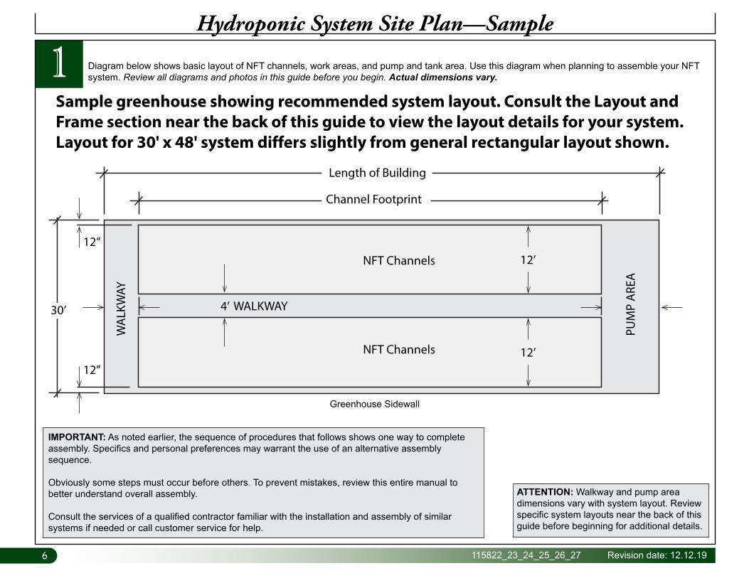
1Hydroponic System Site Plan—Sample
Diagram below shows basic layout of NFT channels, work areas, and pump and tank area. Use this diagram when planning to assemble your NFT system. Review all diagrams and photos in this guide before you begin. Actual dimensions vary.
Sample greenhouse showing recommended system layout. Consult the Layout and Frame section near the back of this guide to view the layout details for your system. Layout for 30' x 48' system differs slightly from general rectangular layout shown.
12’
4’ WALKWAY
NFT Channels
NFT Channels
WA
LKW
AY
PUM
P A
REA
12’
12”
12”
30’
Channel Footprint
Length of Building
Greenhouse Sidewall
ATTENTION: Walkway and pump area dimensions vary with system layout. Review specific system layouts near the back of this guide before beginning for additional details.
IMPORTANT: As noted earlier, the sequence of procedures that follows shows one way to complete assembly. Specifics and personal preferences may warrant the use of an alternative assembly sequence.
Obviously some steps must occur before others. To prevent mistakes, review this entire manual to better understand overall assembly.
Consult the services of a qualified contractor familiar with the installation and assembly of similar systems if needed or call customer service for help.
7Revision date: 12.12.19 115822_23_24_25_26_27
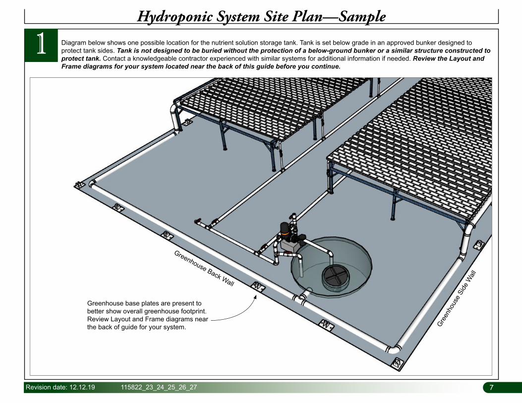
1 Diagram below shows one possible location for the nutrient solution storage tank. Tank is set below grade in an approved bunker designed to protect tank sides. Tank is not designed to be buried without the protection of a below-ground bunker or a similar structure constructed to protect tank. Contact a knowledgeable contractor experienced with similar systems for additional information if needed. Review the Layout and Frame diagrams for your system located near the back of this guide before you continue.
Hydroponic System Site Plan—Sample
Greenhouse base plates are present to better show overall greenhouse footprint. Review Layout and Frame diagrams near the back of guide for your system. Gre
enho
use
Side
Wall
Greenhouse Back Wall
88 115822_23_24_25_26_27 Revision date: 12.12.19
Prepare Site and Set Tank
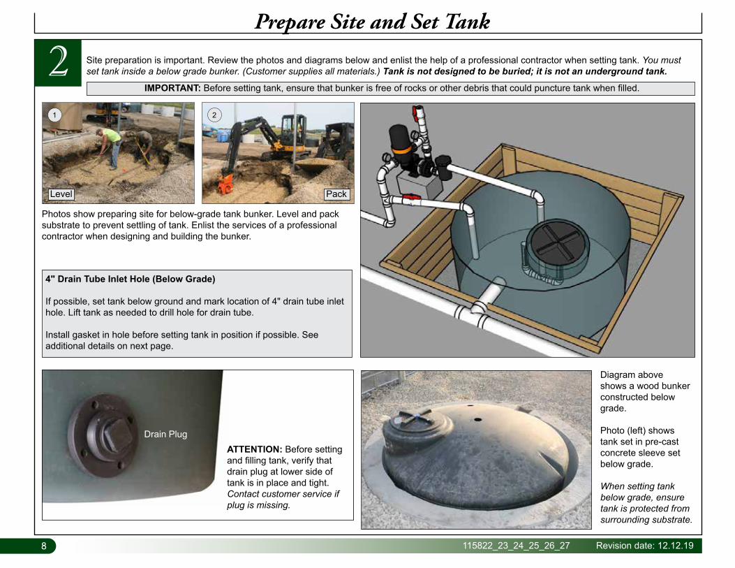
2 Site preparation is important. Review the photos and diagrams below and enlist the help of a professional contractor when setting tank. You must set tank inside a below grade bunker. (Customer supplies all materials.) Tank is not designed to be buried; it is not an underground tank.
IMPORTANT: Before setting tank, ensure that bunker is free of rocks or other debris that could puncture tank when filled.
ATTENTION: Before setting and filling tank, verify that drain plug at lower side of tank is in place and tight. Contact customer service if plug is missing.
Drain Plug
4" Drain Tube Inlet Hole (Below Grade)
If possible, set tank below ground and mark location of 4" drain tube inlet hole. Lift tank as needed to drill hole for drain tube.
Install gasket in hole before setting tank in position if possible. See additional details on next page.
Photos show preparing site for below-grade tank bunker. Level and pack substrate to prevent settling of tank. Enlist the services of a professional contractor when designing and building the bunker.
Diagram above shows a wood bunker constructed below grade.
Photo (left) shows tank set in pre-cast concrete sleeve set below grade.
When setting tank below grade, ensure tank is protected from surrounding substrate.
21
PackLevel
9Revision date: 12.12.19 115822_23_24_25_26_27
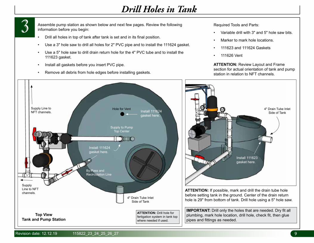
Assemble pump station as shown below and next few pages. Review the following information before you begin:
• Drill all holes in top of tank after tank is set and in its final position.
• Use a 3" hole saw to drill all holes for 2" PVC pipe and to install the 111624 gasket.
• Use a 5" hole saw to drill drain return hole for the 4" PVC tube and to install the 111623 gasket.
• Install all gaskets before you insert PVC pipe.
• Remove all debris from hole edges before installing gaskets.
3Drill Holes in Tank
Required Tools and Parts:
• Variable drill with 3" and 5" hole saw bits.
• Marker to mark hole locations.
• 111623 and 111624 Gaskets
• 111626 Vent
4" Drain Tube InletSide of Tank
ATTENTION: If possible, mark and drill the drain tube hole before setting tank in the ground. Center of the drain return hole is 29" from bottom of tank. Drill hole using a 5" hole saw.
Install 111623 gasket here.
ATTENTION: Drill hole for fertigation system in tank top where needed if used.
By-Pass and Recirculation Line
4" Drain Tube InletSide of Tank
Top ViewTank and Pump Station
Supply to PumpTop Center
Hole for VentSupply Line to NFT channels.
Supply Line to NFT channels.
Install 111624 gasket here.
Install 111624 gasket here.
ATTENTION: Review Layout and Frame section for actual orientation of tank and pump station in relation to NFT channels.
IMPORTANT: Drill only the holes that are needed. Dry fit all plumbing, mark hole location, drill hole, check fit, then glue pipes and fittings as needed.

1010 115822_23_24_25_26_27 Revision date: 12.12.19
Pump
Customer-Supplied Pump Mount
WF3516
WF3516
WF1576
WF1386
WF1386
WF0002
2"
2"
2"
2"
WF1576
WF1576
111152
111160
111153
Attach 111152 Strainer directly to pump intake.
FLOW
Outlet to NFT channels.
Pump and Tank Plumbing Views
3
WF6990PVC Cement
ATTENTION: Prior to cleaning the 111160 filter and to prevent damaging filter gasket, open valve on top of filter cannister to release vacuum.
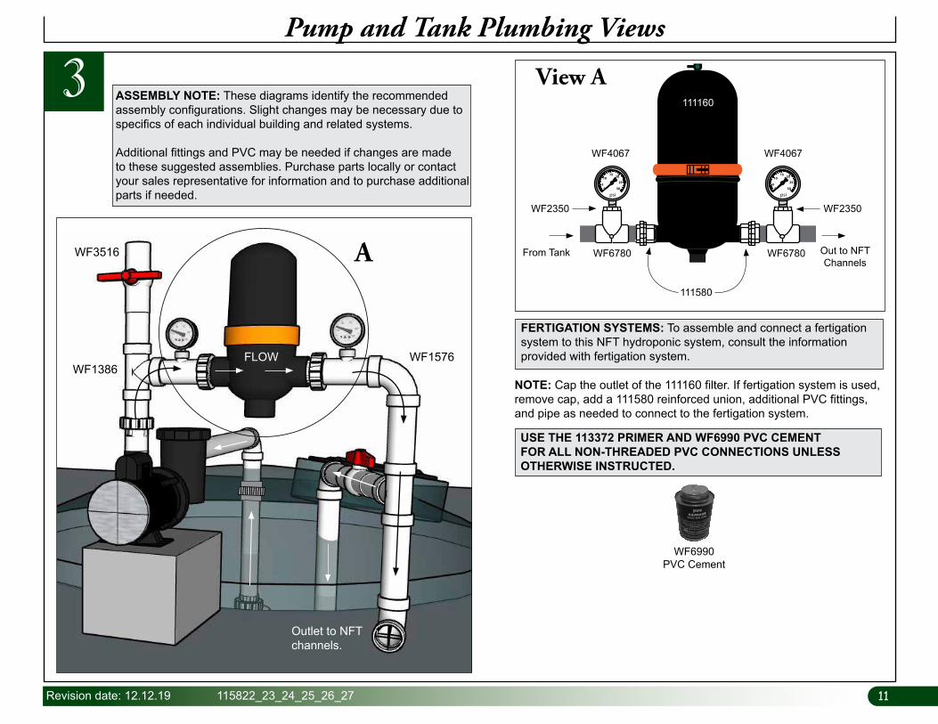
These diagrams identify recommended assembly configurations. Slight changes may be necessary due to specifics of each individual building and related systems. Additional fittings and PVC may be needed if changes are made to these suggested assemblies. Purchase parts locally or contact your sales representative for information and to purchase additional parts if needed.
ASSEMBLY NOTES
• During assembly, wrap all fitting threads with tape before connecting parts. (Does not apply to fittings inside tank.)
• Install filter at a height that allows for disassembly, cleaning, and maintenance.
• Glue all PVC fittings using 113372 PVC primer and WF6990 glue. Apply according to instructions included with products.
• During installation of 111160 filter, confirm water flow direction and install filter accordingly.
CONNECT PUMP TO POWER
Enlist the services of an experienced electrician when connecting power to the pump and other electrical devices.
All wiring to be completed according to established codes and practices.
11Revision date: 12.12.19 115822_23_24_25_26_27
Pump and Tank Plumbing Views
3
FERTIGATION SYSTEMS: To assemble and connect a fertigation system to this NFT hydroponic system, consult the information provided with fertigation system.
USE THE 113372 PRIMER AND WF6990 PVC CEMENT FOR ALL NON-THREADED PVC CONNECTIONS UNLESS OTHERWISE INSTRUCTED.
NOTE: Cap the outlet of the 111160 filter. If fertigation system is used, remove cap, add a 111580 reinforced union, additional PVC fittings, and pipe as needed to connect to the fertigation system.
WF6780 WF6780From Tank Out to NFT Channels
111580
WF4067 WF4067
WF2350WF2350
View A
psi0
5
1015 20
30
25
psi0
5
1015 20
30
25
111160ASSEMBLY NOTE: These diagrams identify the recommended assembly configurations. Slight changes may be necessary due to specifics of each individual building and related systems.
Additional fittings and PVC may be needed if changes are made to these suggested assemblies. Purchase parts locally or contact your sales representative for information and to purchase additional parts if needed.
WF1386
WF3516
WF1576FLOW
A
Outlet to NFT channels.
WF6990PVC Cement
1212 115822_23_24_25_26_27 Revision date: 12.12.19
Pump and Tank Plumbing Views
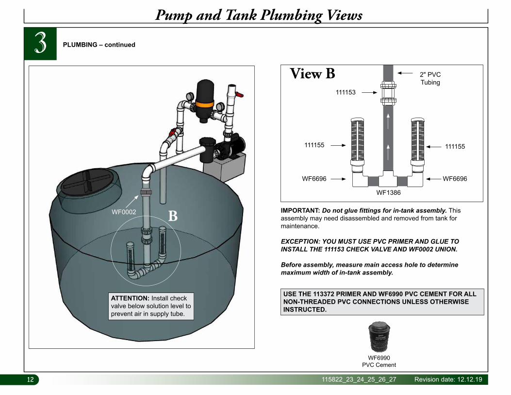
3View B 2" PVC
Tubing
WF6696
WF1386
111155
WF6696
111155
111153
IMPORTANT: Do not glue fittings for in-tank assembly. This assembly may need disassembled and removed from tank for maintenance.
EXCEPTION: YOU MUST USE PVC PRIMER AND GLUE TO INSTALL THE 111153 CHECK VALVE AND WF0002 UNION.
Before assembly, measure main access hole to determine maximum width of in-tank assembly.
USE THE 113372 PRIMER AND WF6990 PVC CEMENT FOR ALL NON-THREADED PVC CONNECTIONS UNLESS OTHERWISE INSTRUCTED.
PLUMBING – continued
WF6990PVC Cement
B
ATTENTION: Install check valve below solution level to prevent air in supply tube.
WF0002

13Revision date: 12.12.19 115822_23_24_25_26_27
4Assemble Support Frames for NFT Channels
ASSEMBLE NFT CHANNEL SUPPORT FRAME
Assemble support frame for NFT channels as shown below. After assembly, use frame to support the individual NFT channels as they are assembled. Position/assemble frame so low (or drain) side is toward the outside greenhouse walls. See diagram for details. Before you begin, consult Layout and Frame section near back of this guide to view your system.
REQUIRED PARTS — Frame Levelers
• 115793 (32") Leg, 115794 (34") Leg, and 115795 (36" Leg)
• 113030S03 Adjustable Footer
• 112477 Frame Leveler Insert
• FALB34B (3/8") Nut
• FA4572B (#12 x 1") Tek Screws and 100442 Nut Driver
Complete these steps:
1. Gather/locate parts shown at right.
2. Assemble adjustable frame leveler components as shown.
3. Insert a leveler into bottom of each leg and secure leveler to leg tube using one (1) FA4572B Tek screw for each leveler. Do not mix leg tubes; keep like leg tubes in separate piles for easier assembly of frame sections.
112477
FALB34BFA4572BTek Screw
ATTENTION: Drive screw through leg tube slightly off center line of tube to prevent contacting threaded rod of adjustable footer. Be sure to drive screw into one of the three sides of insert (Fig. 1). Do not install into open side of insert.
Bottom of Leg Tube
112477
FALB34B Locking Nut
113030S03
x
Fig. 1 Fig. 2
ASSEMBLY NOTE: Install Tek screws using a clutched drill driver running approximately 750 RPM while applying approximately 50 lbs of force.
Do not use an impact driver!
1414 115822_23_24_25_26_27 Revision date: 12.12.19
4Assemble Support Frames for NFT Channels
ASSEMBLE NFT CHANNEL SUPPORT FRAME
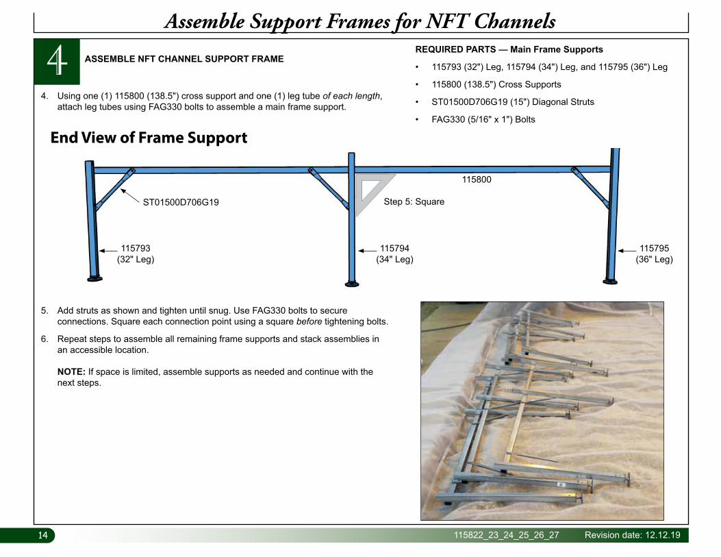
4. Using one (1) 115800 (138.5") cross support and one (1) leg tube of each length, attach leg tubes using FAG330 bolts to assemble a main frame support.
End View of Frame Support
REQUIRED PARTS — Main Frame Supports
• 115793 (32") Leg, 115794 (34") Leg, and 115795 (36") Leg
• 115800 (138.5") Cross Supports
• ST01500D706G19 (15") Diagonal Struts
• FAG330 (5/16" x 1") Bolts
5. Add struts as shown and tighten until snug. Use FAG330 bolts to secure connections. Square each connection point using a square before tightening bolts.
6. Repeat steps to assemble all remaining frame supports and stack assemblies in an accessible location. NOTE: If space is limited, assemble supports as needed and continue with the next steps.
115793 (32" Leg)
115794 (34" Leg)
115795 (36" Leg)
ST01500D706G19
115800
Step 5: Square
15Revision date: 12.12.19 115822_23_24_25_26_27
4Assemble Support Frames for NFT Channels
ASSEMBLE NFT CHANNEL SUPPORT FRAME — continued
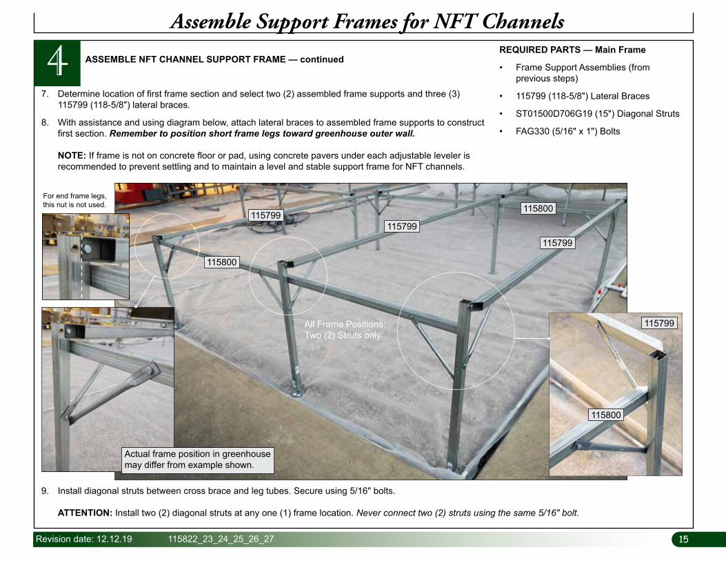
7. Determine location of first frame section and select two (2) assembled frame supports and three (3) 115799 (118-5/8") lateral braces.
8. With assistance and using diagram below, attach lateral braces to assembled frame supports to construct first section. Remember to position short frame legs toward greenhouse outer wall. NOTE: If frame is not on concrete floor or pad, using concrete pavers under each adjustable leveler is recommended to prevent settling and to maintain a level and stable support frame for NFT channels.
REQUIRED PARTS — Main Frame
• Frame Support Assemblies (from previous steps)
• 115799 (118-5/8") Lateral Braces
• ST01500D706G19 (15") Diagonal Struts
• FAG330 (5/16" x 1") Bolts
9. Install diagonal struts between cross brace and leg tubes. Secure using 5/16" bolts. ATTENTION: Install two (2) diagonal struts at any one (1) frame location. Never connect two (2) struts using the same 5/16" bolt.
115799
115800
115800115799
115799
All Frame Positions: Two (2) Struts only.
Actual frame position in greenhouse may differ from example shown.
For end frame legs, this nut is not used.
115799
115800
1616 115822_23_24_25_26_27 Revision date: 12.12.19
Assemble Support Frames for NFT Channels
4 ASSEMBLE NFT CHANNEL SUPPORT FRAME — continued
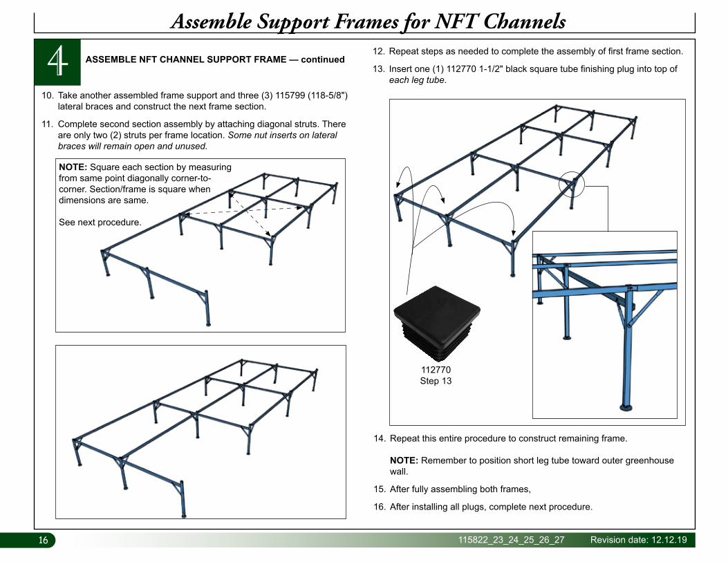
10. Take another assembled frame support and three (3) 115799 (118-5/8") lateral braces and construct the next frame section.
11. Complete second section assembly by attaching diagonal struts. There are only two (2) struts per frame location. Some nut inserts on lateral braces will remain open and unused.
12. Repeat steps as needed to complete the assembly of first frame section.
13. Insert one (1) 112770 1-1/2" black square tube finishing plug into top of each leg tube.
14. Repeat this entire procedure to construct remaining frame. NOTE: Remember to position short leg tube toward outer greenhouse wall.
15. After fully assembling both frames,
16. After installing all plugs, complete next procedure.
NOTE: Square each section by measuring from same point diagonally corner-to-corner. Section/frame is square when dimensions are same.
See next procedure.
112770Step 13
17Revision date: 12.12.19 115822_23_24_25_26_27
Square and Level Frames
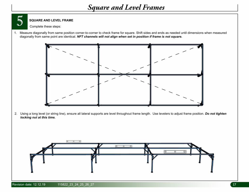
5 SQUARE AND LEVEL FRAME
1. Measure diagonally from same position corner-to-corner to check frame for square. Shift sides and ends as needed until dimensions when measured diagonally from same point are identical. NFT channels will not align when set in position if frame is not square.
Complete these steps:
2. Using a long level (or string line), ensure all lateral supports are level throughout frame length. Use levelers to adjust frame position. Do not tighten locking nut at this time.
1818 115822_23_24_25_26_27 Revision date: 12.12.19
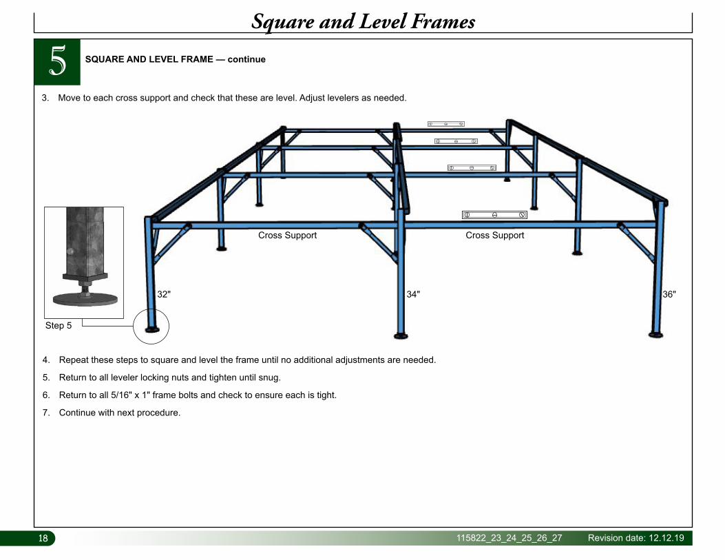
36"34"32"
Step 5
Square and Level Frames
5 SQUARE AND LEVEL FRAME — continue
3. Move to each cross support and check that these are level. Adjust levelers as needed.
4. Repeat these steps to square and level the frame until no additional adjustments are needed.
5. Return to all leveler locking nuts and tighten until snug.
6. Return to all 5/16" x 1" frame bolts and check to ensure each is tight.
7. Continue with next procedure.
Cross SupportCross Support
19Revision date: 12.12.19 115822_23_24_25_26_27
Attach 4" Drain Tube Support Brackets
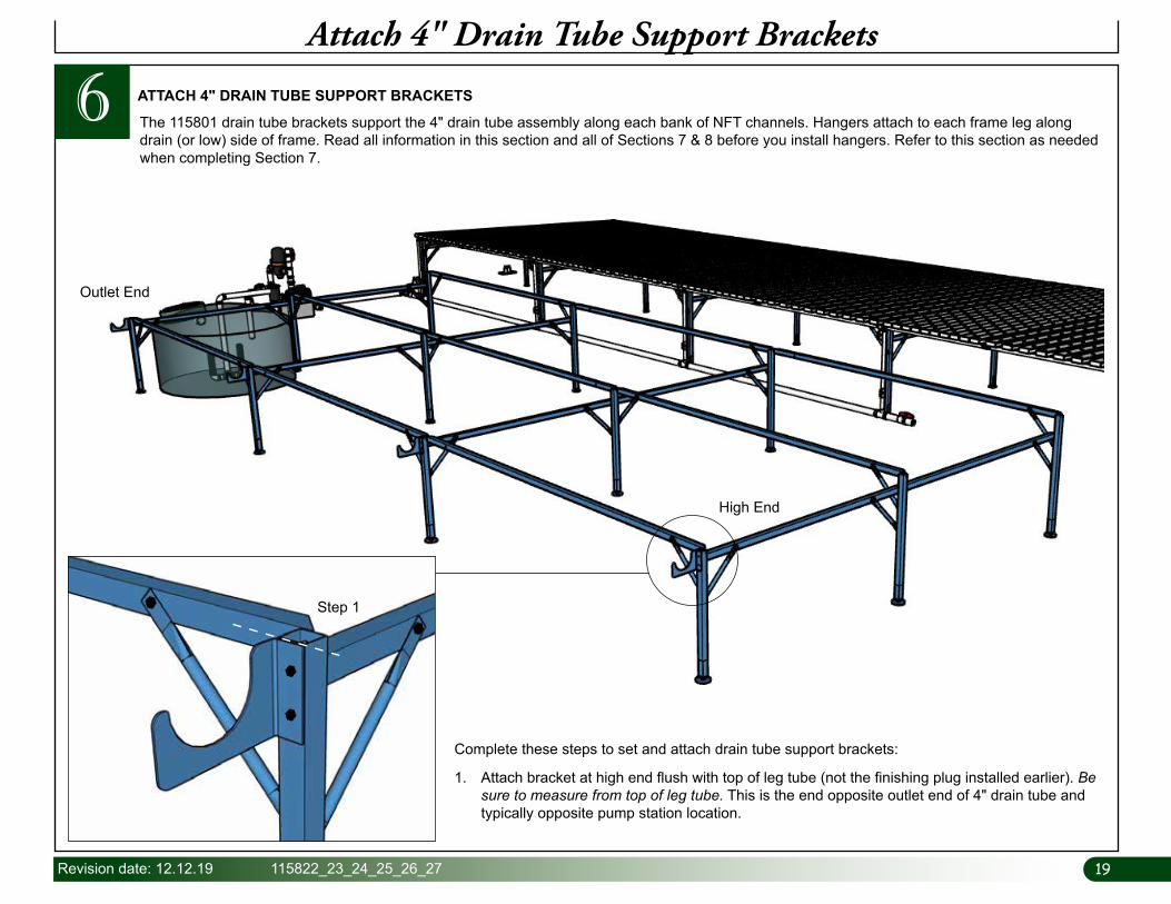
6 ATTACH 4" DRAIN TUBE SUPPORT BRACKETS
The 115801 drain tube brackets support the 4" drain tube assembly along each bank of NFT channels. Hangers attach to each frame leg along drain (or low) side of frame. Read all information in this section and all of Sections 7 & 8 before you install hangers. Refer to this section as needed when completing Section 7.
High End
Outlet End
Complete these steps to set and attach drain tube support brackets:
1. Attach bracket at high end flush with top of leg tube (not the finishing plug installed earlier). Be sure to measure from top of leg tube. This is the end opposite outlet end of 4" drain tube and typically opposite pump station location.
Step 1
2020 115822_23_24_25_26_27 Revision date: 12.12.19
Attach 4" Drain Tube Support Brackets
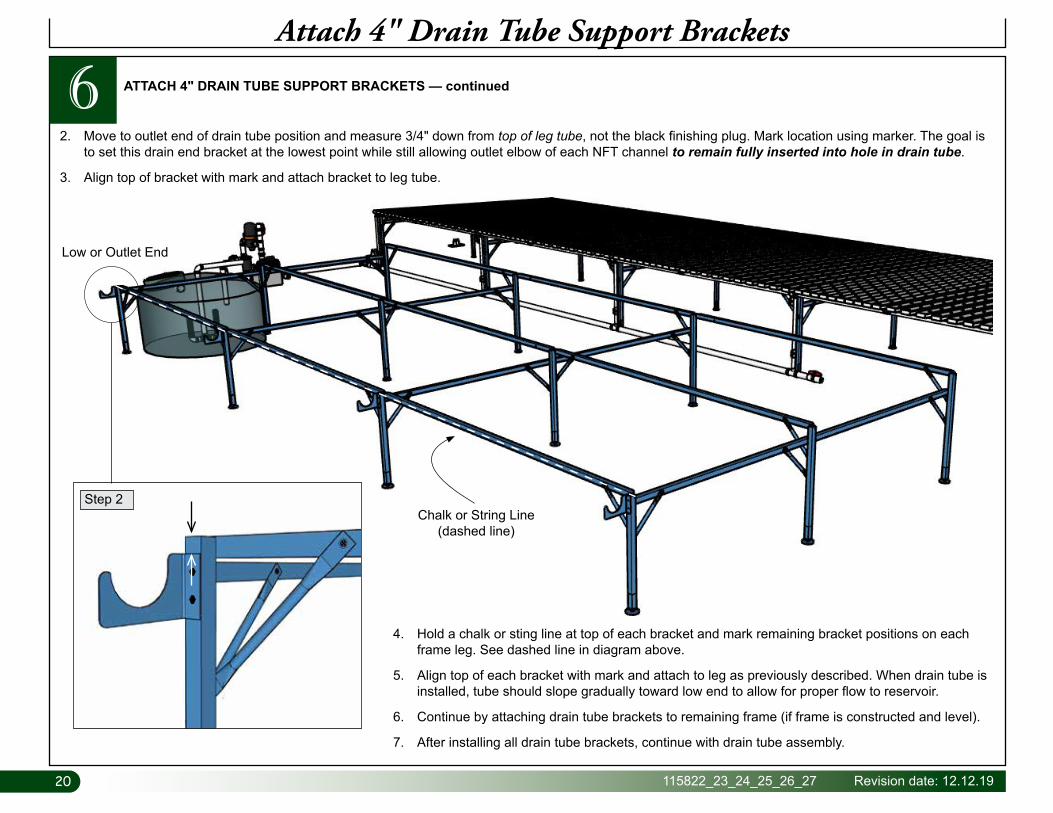
6 ATTACH 4" DRAIN TUBE SUPPORT BRACKETS — continued
Low or Outlet End
2. Move to outlet end of drain tube position and measure 3/4" down from top of leg tube, not the black finishing plug. Mark location using marker. The goal is to set this drain end bracket at the lowest point while still allowing outlet elbow of each NFT channel to remain fully inserted into hole in drain tube.
3. Align top of bracket with mark and attach bracket to leg tube.
4. Hold a chalk or sting line at top of each bracket and mark remaining bracket positions on each frame leg. See dashed line in diagram above.
5. Align top of each bracket with mark and attach to leg as previously described. When drain tube is installed, tube should slope gradually toward low end to allow for proper flow to reservoir.
6. Continue by attaching drain tube brackets to remaining frame (if frame is constructed and level).
7. After installing all drain tube brackets, continue with drain tube assembly.
Chalk or String Line(dashed line)
Step 2
21Revision date: 12.12.19 115822_23_24_25_26_27
Construct 4" Drain Tube
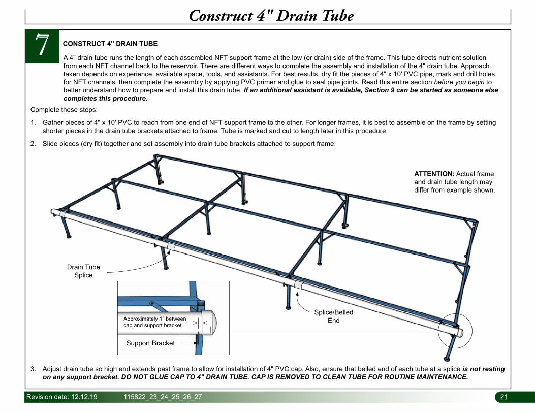
7 CONSTRUCT 4" DRAIN TUBE
Complete these steps:
1. Gather pieces of 4" x 10' PVC to reach from one end of NFT support frame to the other. For longer frames, it is best to assemble on the frame by setting shorter pieces in the drain tube brackets attached to frame. Tube is marked and cut to length later in this procedure.
2. Slide pieces (dry fit) together and set assembly into drain tube brackets attached to support frame.
A 4" drain tube runs the length of each assembled NFT support frame at the low (or drain) side of the frame. This tube directs nutrient solution from each NFT channel back to the reservoir. There are different ways to complete the assembly and installation of the 4" drain tube. Approach taken depends on experience, available space, tools, and assistants. For best results, dry fit the pieces of 4" x 10' PVC pipe, mark and drill holes for NFT channels, then complete the assembly by applying PVC primer and glue to seal pipe joints. Read this entire section before you begin to better understand how to prepare and install this drain tube. If an additional assistant is available, Section 9 can be started as someone else completes this procedure.
3. Adjust drain tube so high end extends past frame to allow for installation of 4" PVC cap. Also, ensure that belled end of each tube at a splice is not resting on any support bracket. DO NOT GLUE CAP TO 4" DRAIN TUBE. CAP IS REMOVED TO CLEAN TUBE FOR ROUTINE MAINTENANCE.
Approximately 1" between cap and support bracket.
ATTENTION: Actual frame and drain tube length may differ from example shown.
Drain Tube Splice
Support Bracket
Splice/Belled End
2222 115822_23_24_25_26_27 Revision date: 12.12.19
Construct 4" Drain Tube
7 CONSTRUCT 4" DRAIN TUBE — continued
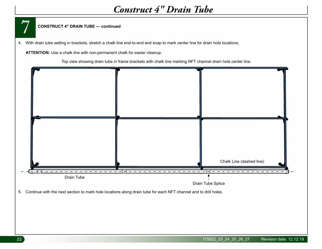
4. With drain tube setting in brackets, stretch a chalk line end-to-end and snap to mark center line for drain hole locations. ATTENTION: Use a chalk line with non-permanent chalk for easier cleanup.
Top view showing drain tube in frame brackets with chalk line marking NFT channel drain hole center line.
5. Continue with the next section to mark hole locations along drain tube for each NFT channel and to drill holes.
Drain Tube
Chalk Line (dashed line)
Drain Tube Splice
23Revision date: 12.12.19 115822_23_24_25_26_27
4" Drain Tube
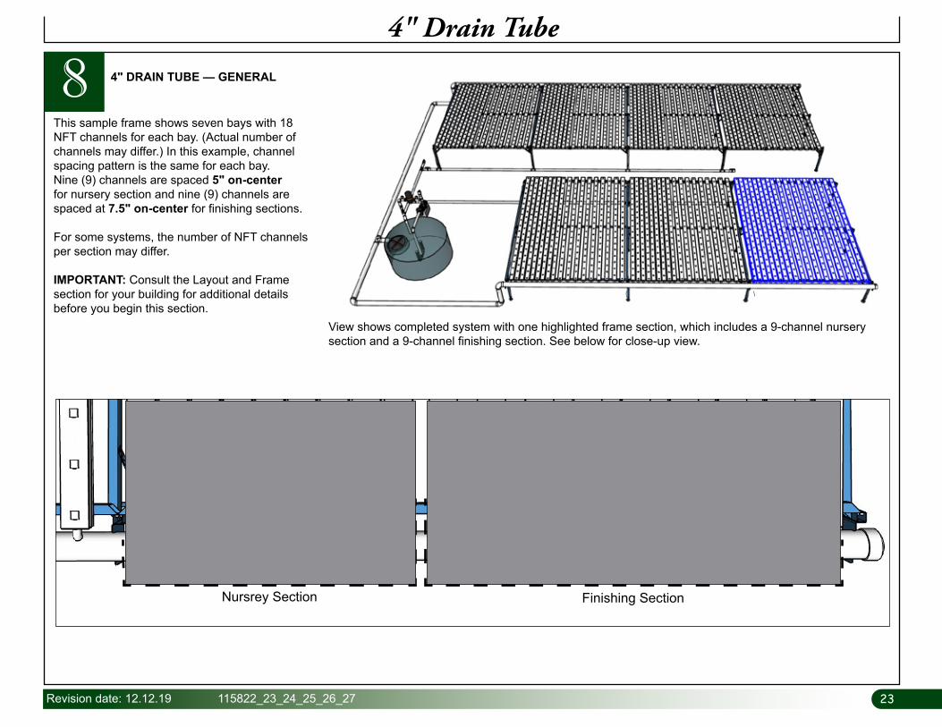
8 4" DRAIN TUBE — GENERAL
This sample frame shows seven bays with 18 NFT channels for each bay. (Actual number of channels may differ.) In this example, channel spacing pattern is the same for each bay. Nine (9) channels are spaced 5" on-center for nursery section and nine (9) channels are spaced at 7.5" on-center for finishing sections.
For some systems, the number of NFT channels per section may differ.
IMPORTANT: Consult the Layout and Frame section for your building for additional details before you begin this section.
View shows completed system with one highlighted frame section, which includes a 9-channel nursery section and a 9-channel finishing section. See below for close-up view.
Nursrey Section Finishing Section
2424 115822_23_24_25_26_27 Revision date: 12.12.19
Drill Holes in 4" Drain Tube
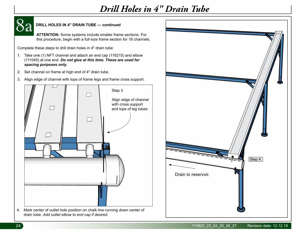
8a DRILL HOLES IN 4" DRAIN TUBE — continued
Complete these steps to drill drain holes in 4" drain tube:
1. Take one (1) NFT channel and attach an end cap (116215) and elbow (111045) at one end. Do not glue at this time. These are used for spacing purposes only.
2. Set channel on frame at high end of 4" drain tube.
3. Align edge of channel with tops of frame legs and frame cross support.
Drain to reservoir.
4. Mark center of outlet hole position on chalk line running down center of drain tube. Add outlet elbow to end cap if desired.
Step 3
Align edge of channel with cross support and tops of leg tubes.
Step 4
ATTENTION: Some systems include smaller frame sections. For this procedure, begin with a full-size frame section for 18 channels.
25Revision date: 12.12.19 115822_23_24_25_26_27
Drill Holes in 4" Drain Tube
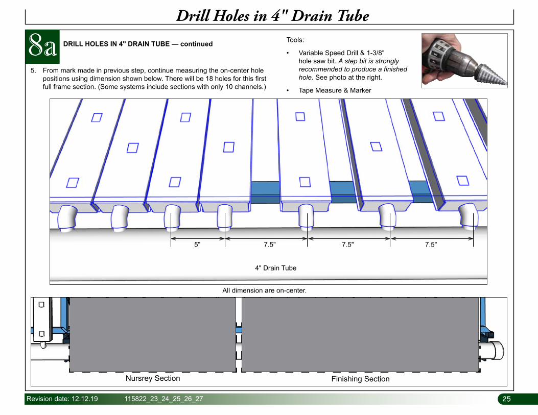
DRILL HOLES IN 4" DRAIN TUBE — continued
All dimension are on-center.
Tools:
• Variable Speed Drill & 1-3/8" hole saw bit. A step bit is strongly recommended to produce a finished hole. See photo at the right.
• Tape Measure & Marker
5. From mark made in previous step, continue measuring the on-center hole positions using dimension shown below. There will be 18 holes for this first full frame section. (Some systems include sections with only 10 channels.)
8a
5" 7.5"
4" Drain Tube
7.5" 7.5"
Nursrey Section Finishing Section
2626 115822_23_24_25_26_27 Revision date: 12.12.19
Drill Holes in 4" Drain Tube
DRILL HOLES IN 4" DRAIN TUBE — continued
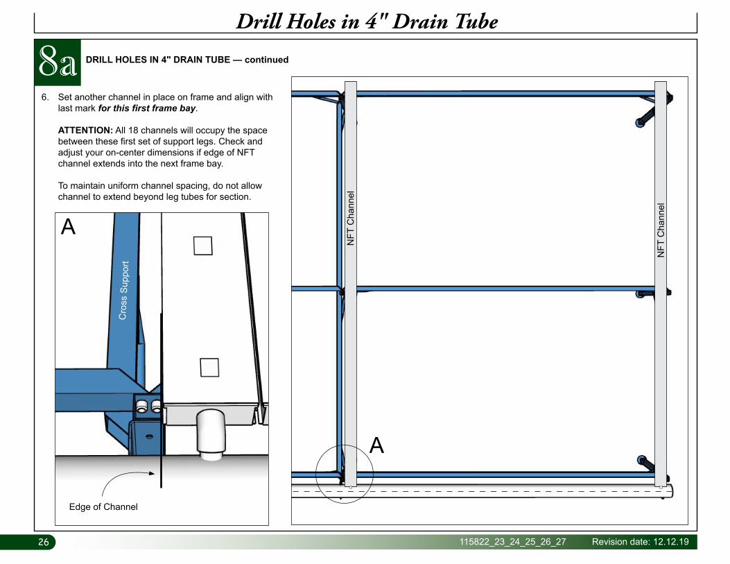
6. Set another channel in place on frame and align with last mark for this first frame bay. ATTENTION: All 18 channels will occupy the space between these first set of support legs. Check and adjust your on-center dimensions if edge of NFT channel extends into the next frame bay. To maintain uniform channel spacing, do not allow channel to extend beyond leg tubes for section.
NFT
Cha
nnel
NFT
Cha
nnel
A
A
Edge of Channel
Cro
ss S
uppo
rt
8a
27Revision date: 12.12.19 115822_23_24_25_26_27
Drill Holes in 4" Drain Tube
DRILL HOLES IN 4" DRAIN TUBE — continued
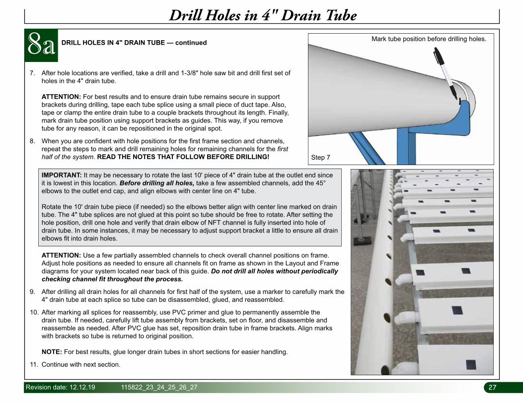
7. After hole locations are verified, take a drill and 1-3/8" hole saw bit and drill first set of holes in the 4" drain tube. ATTENTION: For best results and to ensure drain tube remains secure in support brackets during drilling, tape each tube splice using a small piece of duct tape. Also, tape or clamp the entire drain tube to a couple brackets throughout its length. Finally, mark drain tube position using support brackets as guides. This way, if you remove tube for any reason, it can be repositioned in the original spot.
8. When you are confident with hole positions for the first frame section and channels, repeat the steps to mark and drill remaining holes for remaining channels for the first half of the system. READ THE NOTES THAT FOLLOW BEFORE DRILLING!
Mark tube position before drilling holes.
ATTENTION: Use a few partially assembled channels to check overall channel positions on frame. Adjust hole positions as needed to ensure all channels fit on frame as shown in the Layout and Frame diagrams for your system located near back of this guide. Do not drill all holes without periodically checking channel fit throughout the process.
9. After drilling all drain holes for all channels for first half of the system, use a marker to carefully mark the 4" drain tube at each splice so tube can be disassembled, glued, and reassembled.
10. After marking all splices for reassembly, use PVC primer and glue to permanently assemble the drain tube. If needed, carefully lift tube assembly from brackets, set on floor, and disassemble and reassemble as needed. After PVC glue has set, reposition drain tube in frame brackets. Align marks with brackets so tube is returned to original position. NOTE: For best results, glue longer drain tubes in short sections for easier handling.
11. Continue with next section.
IMPORTANT: It may be necessary to rotate the last 10' piece of 4" drain tube at the outlet end since it is lowest in this location. Before drilling all holes, take a few assembled channels, add the 45° elbows to the outlet end cap, and align elbows with center line on 4" tube. Rotate the 10' drain tube piece (if needed) so the elbows better align with center line marked on drain tube. The 4" tube splices are not glued at this point so tube should be free to rotate. After setting the hole position, drill one hole and verify that drain elbow of NFT channel is fully inserted into hole of drain tube. In some instances, it may be necessary to adjust support bracket a little to ensure all drain elbows fit into drain holes.
Step 7
8a
2828 115822_23_24_25_26_27 Revision date: 12.12.19
Connect 4" Drain Tube to Reservoir
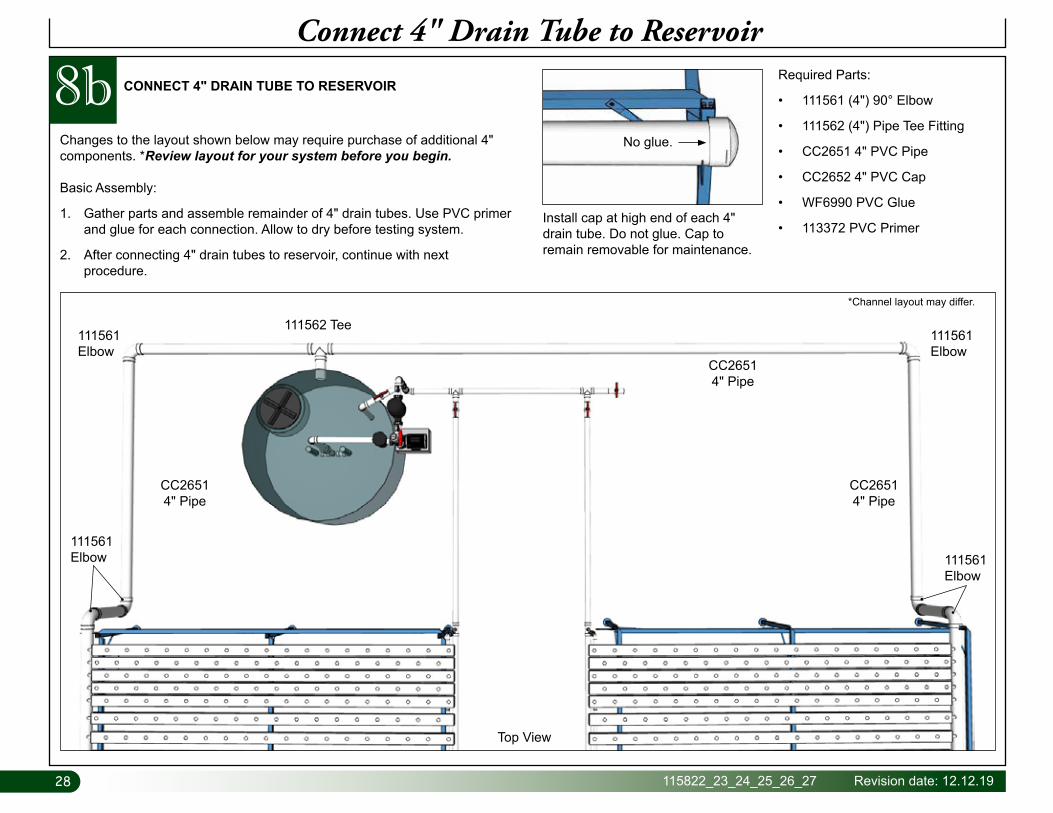
CONNECT 4" DRAIN TUBE TO RESERVOIR
Changes to the layout shown below may require purchase of additional 4" components. *Review layout for your system before you begin.
Basic Assembly:
1. Gather parts and assemble remainder of 4" drain tubes. Use PVC primer and glue for each connection. Allow to dry before testing system.
2. After connecting 4" drain tubes to reservoir, continue with next procedure.
Required Parts:
• 111561 (4") 90° Elbow
• 111562 (4") Pipe Tee Fitting
• CC2651 4" PVC Pipe
• CC2652 4" PVC Cap
• WF6990 PVC Glue
• 113372 PVC PrimerInstall cap at high end of each 4" drain tube. Do not glue. Cap to remain removable for maintenance.
No glue.
8b
111561 Elbow
111561 Elbow
111562 Tee
CC26514" Pipe
CC26514" Pipe
CC26514" Pipe
111561 Elbow
111561 Elbow
Top View
*Channel layout may differ.
29Revision date: 12.12.19 115822_23_24_25_26_27
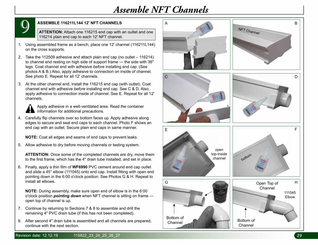
91. Using assembled frame as a bench, place one 12' channel (116211L144)
on the cross supports.
2. Take the 112509 adhesive and attach plain end cap (no outlet – 116214) to channel end resting on high side of support frame — the side with 36" legs. Coat channel end with adhesive before installing end cap. (See photos A & B.) Also, apply adhesive to connection on inside of channel. See photo E. Repeat for all 12' channels.
3. At the other channel end, install the 116215 end cap (with outlet). Coat channel end with adhesive before installing end cap. See C & D. Also, apply adhesive to connection inside of channel. See E. Repeat for all 12' channels.
ASSEMBLE 116211L144 12' NFT CHANNELS
4. Carefully flip channels over so bottom faces up. Apply adhesive along edges to secure and seal end caps to each channel. Photo F shows an end cap with an outlet. Secure plain end caps in same manner. NOTE: Coat all edges and seams of end caps to prevent leaks.
5. Allow adhesive to dry before moving channels or testing system. ATTENTION: Once some of the completed channels are dry, move them to the first frame, which has the 4" drain tube installed, and set in place.
6. Finally, apply a thin film of WF6990 PVC cement around end cap outlet and slide a 45° elbow (111045) onto end cap. Install fitting with open end pointing down in the 6:00 o'clock position. See Photos G & H. Repeat to install all elbows. NOTE: During assembly, make sure open end of elbow is in the 6:00 o'clock position pointing down when NFT channel is sitting on frame —open top of channel is up.
7. Continue by returning to Sections 7 & 8 to assemble and drill the remaining 4" PVC drain tube (if this has not been completed).
8. After second 4" drain tube is assembled and all channels are prepared, continue with the next section.
Apply adhesive in a well-ventilated area. Read the container information for additional precautions.
Assemble NFT Channels
ATTENTION: Attach one 116215 end cap with an outlet and one 116214 plain end cap to each 12' NFT channel.
A B
C D
G
111045 Elbow
NFT Channel
open top-inside channel bottom
E F
H
Bottom of Channel Bottom of
Channel
Open Top of Channel
3030 115822_23_24_25_26_27 Revision date: 12.12.19
Prepare and Install 2" PVC Supply Lines
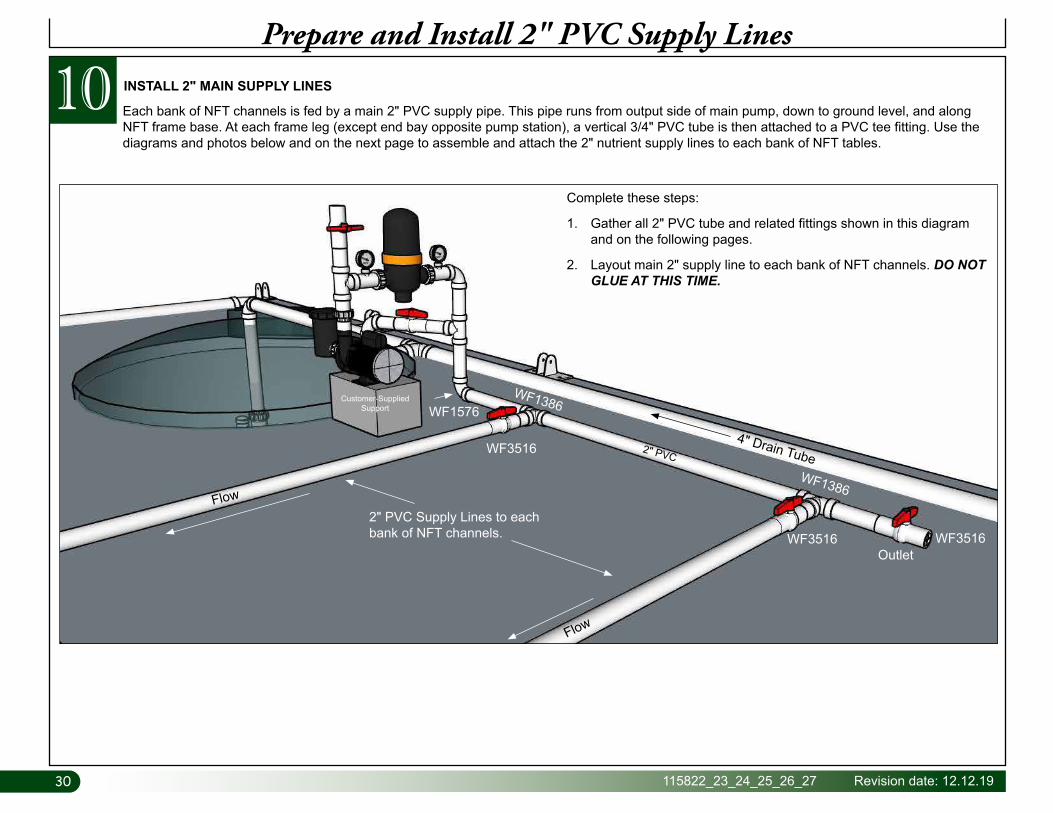
Each bank of NFT channels is fed by a main 2" PVC supply pipe. This pipe runs from output side of main pump, down to ground level, and along NFT frame base. At each frame leg (except end bay opposite pump station), a vertical 3/4" PVC tube is then attached to a PVC tee fitting. Use the diagrams and photos below and on the next page to assemble and attach the 2" nutrient supply lines to each bank of NFT tables.
10
2" PVC Supply Lines to each bank of NFT channels.
Outlet
Flow
Flow
4" Drain TubeWF1386
WF1386
2" PVCWF3516
WF1576
WF3516 WF3516
Customer-Supplied Support
Complete these steps:
1. Gather all 2" PVC tube and related fittings shown in this diagram and on the following pages.
2. Layout main 2" supply line to each bank of NFT channels. DO NOT GLUE AT THIS TIME.
INSTALL 2" MAIN SUPPLY LINES
31Revision date: 12.12.19 115822_23_24_25_26_27
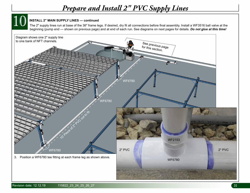
10 The 2" supply lines run at base of the 36" frame legs. If desired, dry fit all connections before final assembly. Install a WF3516 ball valve at the beginning (pump end — shown on previous page) and at end of each run. See diagrams on next pages for details. Do not glue at this time!
INSTALL 2" MAIN SUPPLY LINES — continued
Prepare and Install 2" PVC Supply Lines
WF6780
WF6780
WF6780
Diagram shows one 2" supply line to one bank of NFT channels.
10' P
iece o
f 2" P
VC cut to
fit.
See previous page for this section.
WF2153
3. Position a WF6780 tee fitting at each frame leg as shown above.WF6780
2" PVC2" PVC
WF2153
3232 115822_23_24_25_26_27 Revision date: 12.12.19
WF3516
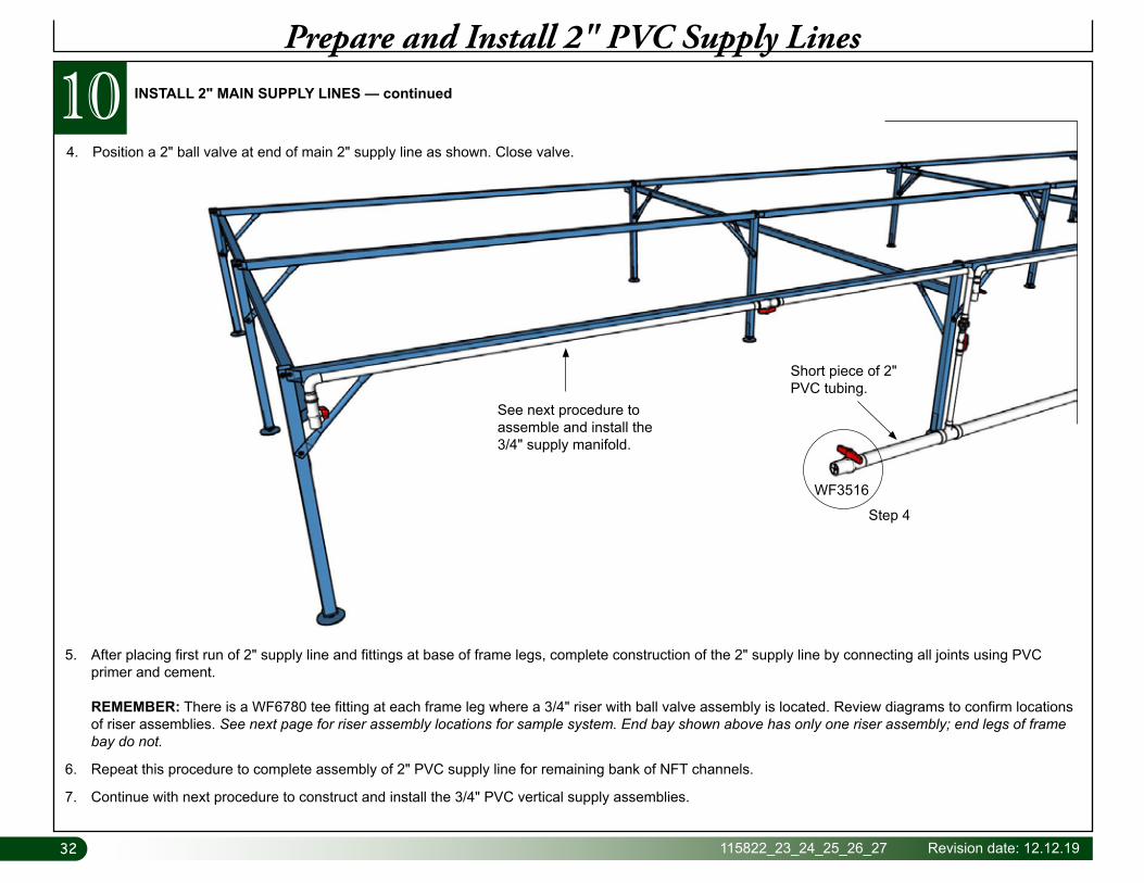
Short piece of 2" PVC tubing.
See next procedure to assemble and install the 3/4" supply manifold.
Step 4
INSTALL 2" MAIN SUPPLY LINES — continued104. Position a 2" ball valve at end of main 2" supply line as shown. Close valve.
Prepare and Install 2" PVC Supply Lines
5. After placing first run of 2" supply line and fittings at base of frame legs, complete construction of the 2" supply line by connecting all joints using PVC primer and cement. REMEMBER: There is a WF6780 tee fitting at each frame leg where a 3/4" riser with ball valve assembly is located. Review diagrams to confirm locations of riser assemblies. See next page for riser assembly locations for sample system. End bay shown above has only one riser assembly; end legs of frame bay do not.
6. Repeat this procedure to complete assembly of 2" PVC supply line for remaining bank of NFT channels.
7. Continue with next procedure to construct and install the 3/4" PVC vertical supply assemblies.

33Revision date: 12.12.19 115822_23_24_25_26_27
11 ASSEMBLE AND INSTALL 3/4" PVC RISER & MANIFOLD ASSEMBLIES
Construct 3/4" PVC Riser & Manifold Assemblies
2" PVC Main Supply Lines from Pump
Station
3/4" PVC Riser with Ball Valve Assembly
The 3/4" riser and manifold assemblies supply nutrient solution from 2" main supply lines to each bank of NFT channels. It is best to complete one assembly first and fit it to the frame to ensure all dimensions are accurate for one NFT section. Dry fit the assembly first then fit to frame. Glue all connections after you are certain the assembly is constructed accurately.
The procedure that follows describes one way to construct and install the 3/4" riser and manifold assemblies. To best understand how to construct the riser assemblies, begin by assembling a complete riser and manifold for a full frame section consisting of 18 NFT channels: nine (9) for finishing section and nine (9) for nursery section as described.
3434 115822_23_24_25_26_27 Revision date: 12.12.19
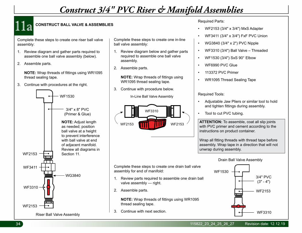
CONSTRUCT BALL VALVE & ASSEMBLIES
Construct 3/4" PVC Riser & Manifold AssembliesRequired Parts:
• WF2153 (3/4" x 3/4") MxS Adapter
• WF3411 (3/4" x 3/4") FxF PVC Union
• WG3840 (3/4" x 2") PVC Nipple
• WF3310 (3/4") Ball Valve – Threaded
• WF1530 (3/4") SxS 90° Elbow
• WF6990 PVC Glue
• 113372 PVC Primer
• WR1095 Thread Sealing Tape
Required Tools:
• Adjustable Jaw Pliers or similar tool to hold and tighten fittings during assembly.
• Tool to cut PVC tubing.
Complete these steps to create one riser ball valve assembly:
1. Review diagram and gather parts required to assemble one ball valve assembly (below).
2. Assemble parts. NOTE: Wrap threads of fittings using WR1095 thread sealing tape.
3. Continue with procedures at the right.
Complete these steps to create one in-line ball valve assembly:
1. Review diagram below and gather parts required to assemble one ball valve assembly.
2. Assemble parts. NOTE: Wrap threads of fittings using WR1095 thread sealing tape.
3. Continue with procedure below.
Complete these steps to create one drain ball valve assembly for end of manifold:
1. Review parts required to assemble one drain ball valve assembly — right.
2. Assemble parts. NOTE: Wrap threads of fittings using WR1095 thread sealing tape.
3. Continue with next section.
ATTENTION: To assemble, coat all slip joints with PVC primer and cement according to the instructions on product container.
Wrap all fitting threads with thread tape before assembly. Wrap tape in a direction that will not unwrap during assembly.
WF2153 WF2153
In-Line Ball Valve Assembly
WF3310
WF2153
WF1530
Drain Ball Valve Assembly
3/4" PVC(3" - 4")
WF3310
11a
Riser Ball Valve Assembly
WF3411
WF3310
WG3840
3/4" x 8" PVC(Primer & Glue)
WF1530
NOTE: Adjust length as needed; position ball valve at a height to prevent interference with ball valve at end of adjacent manifold. Review all diagrams in Section 11.WF2153
WF2153
35Revision date: 12.12.19 115822_23_24_25_26_27
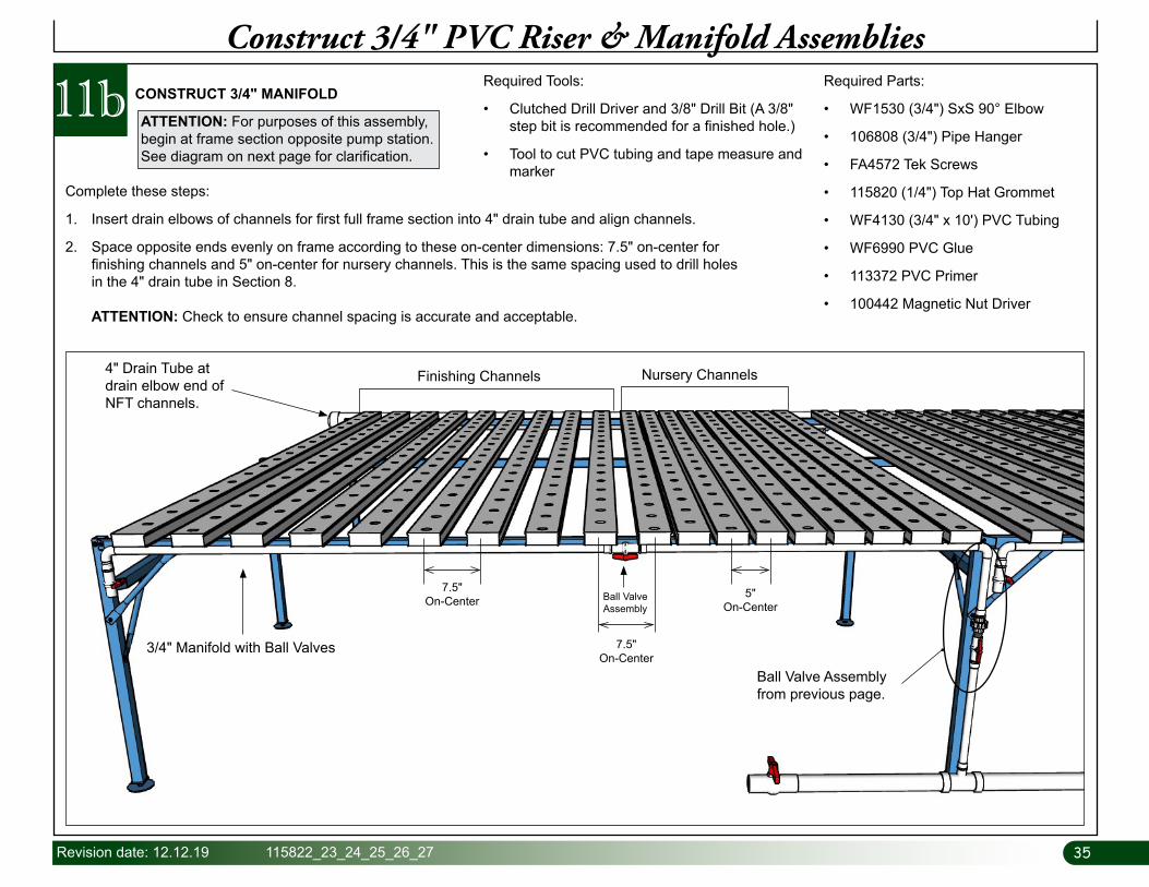
11b CONSTRUCT 3/4" MANIFOLD
Construct 3/4" PVC Riser & Manifold AssembliesRequired Parts:
• WF1530 (3/4") SxS 90° Elbow
• 106808 (3/4") Pipe Hanger
• FA4572 Tek Screws
• 115820 (1/4") Top Hat Grommet
• WF4130 (3/4" x 10') PVC Tubing
• WF6990 PVC Glue
• 113372 PVC Primer
• 100442 Magnetic Nut Driver
Required Tools:
• Clutched Drill Driver and 3/8" Drill Bit (A 3/8" step bit is recommended for a finished hole.)
• Tool to cut PVC tubing and tape measure and marker
3/4" Manifold with Ball Valves
Finishing Channels Nursery Channels
7.5"On-Center
5"On-Center
4" Drain Tube at drain elbow end of NFT channels.
Ball Valve Assembly from previous page.
7.5"On-Center
Ball ValveAssembly
Complete these steps:
1. Insert drain elbows of channels for first full frame section into 4" drain tube and align channels.
2. Space opposite ends evenly on frame according to these on-center dimensions: 7.5" on-center for finishing channels and 5" on-center for nursery channels. This is the same spacing used to drill holes in the 4" drain tube in Section 8. ATTENTION: Check to ensure channel spacing is accurate and acceptable.
ATTENTION: For purposes of this assembly, begin at frame section opposite pump station. See diagram on next page for clarification.
3636 115822_23_24_25_26_27 Revision date: 12.12.19
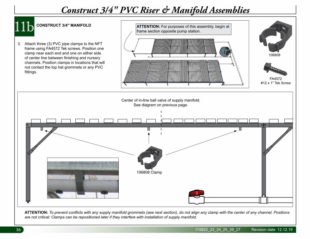
11b CONSTRUCT 3/4" MANIFOLD
Construct 3/4" PVC Riser & Manifold Assemblies
3. Attach three (3) PVC pipe clamps to the NFT frame using FA4572 Tek screws. Position one clamp near each end and one on either side of center line between finishing and nursery channels. Position clamps in locations that will not contact the top hat grommets or any PVC fittings.
106808
FA4572#12 x 1" Tek Screw
ATTENTION: To prevent conflicts with any supply manifold grommets (see next section), do not align any clamp with the center of any channel. Positions are not critical: Clamps can be repositioned later if they interfere with installation of supply manifold.
Center of in-line ball valve of supply manifold. See diagram on previous page.
106808 Clamp
ATTENTION: For purposes of this assembly, begin at frame section opposite pump station.

37Revision date: 12.12.19 115822_23_24_25_26_27
CONSTRUCT 3/4" MANIFOLD — continued11bConstruct 3/4" PVC Riser & Manifold Assemblies
6. After confirming ball valve position, cut PVC tube to length and dry fit ball valve assembly to PVC tube.
7. Take a marker and mark fitting positions on PVC tube at each end.
Step 6
Step 7
4. Take a stick of 3/4" PVC and dry fit the 3/4" ball valve assembly to one end of the PVC tube. With assistance, carefully center the assembly against frame leg and under the lateral frame support. Clamp in place. You do not need to fully close the pipe clamps installed earlier.
5. Mark the in-line ball valve position on the PVC tube. Ball valve is positioned between finishing channels and nursery channels.
ATTENTION: Actual system may differ. Manifold shown with an optional in-line Y-filter.
3838 115822_23_24_25_26_27 Revision date: 12.12.19
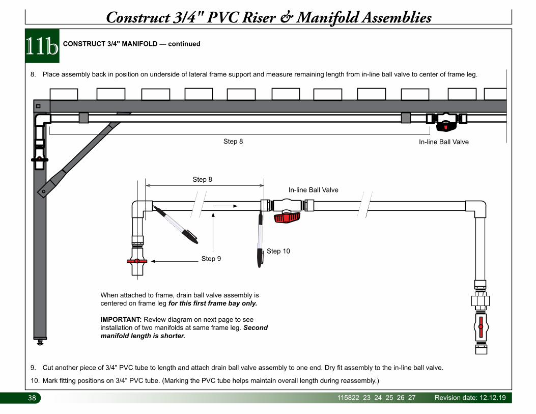
11bConstruct 3/4" PVC Riser & Manifold Assemblies
8. Place assembly back in position on underside of lateral frame support and measure remaining length from in-line ball valve to center of frame leg.
CONSTRUCT 3/4" MANIFOLD — continued
9. Cut another piece of 3/4" PVC tube to length and attach drain ball valve assembly to one end. Dry fit assembly to the in-line ball valve.
10. Mark fitting positions on 3/4" PVC tube. (Marking the PVC tube helps maintain overall length during reassembly.)
When attached to frame, drain ball valve assembly is centered on frame leg for this first frame bay only.
IMPORTANT: Review diagram on next page to see installation of two manifolds at same frame leg. Second manifold length is shorter.
Step 8
In-line Ball Valve
In-line Ball Valve
Step 9Step 10
Step 8
39Revision date: 12.12.19 115822_23_24_25_26_27
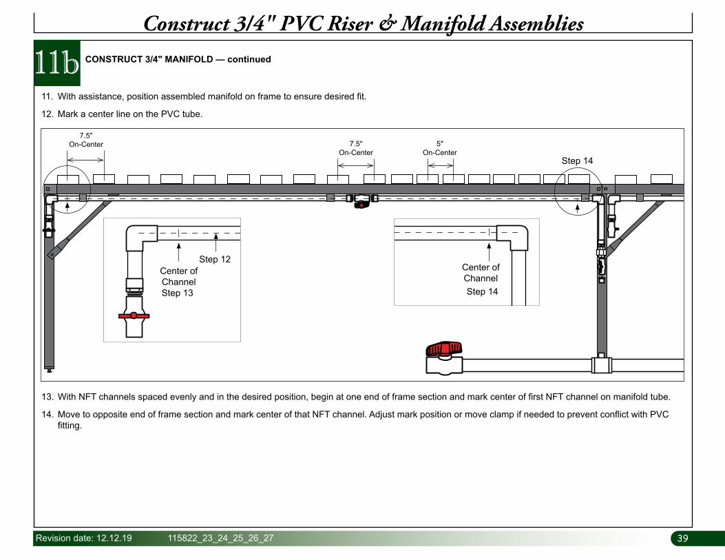
11bConstruct 3/4" PVC Riser & Manifold Assemblies
CONSTRUCT 3/4" MANIFOLD — continued
11. With assistance, position assembled manifold on frame to ensure desired fit.
12. Mark a center line on the PVC tube.
13. With NFT channels spaced evenly and in the desired position, begin at one end of frame section and mark center of first NFT channel on manifold tube.
14. Move to opposite end of frame section and mark center of that NFT channel. Adjust mark position or move clamp if needed to prevent conflict with PVC fitting.
7.5"On-Center
5"On-Center
7.5"On-Center
Step 14
Step 14
Step 13
Step 12Center of Channel
Center of Channel
4040 115822_23_24_25_26_27 Revision date: 12.12.19
11bConstruct 3/4" PVC Riser & Manifold Assemblies
CONSTRUCT 3/4" MANIFOLD — continued
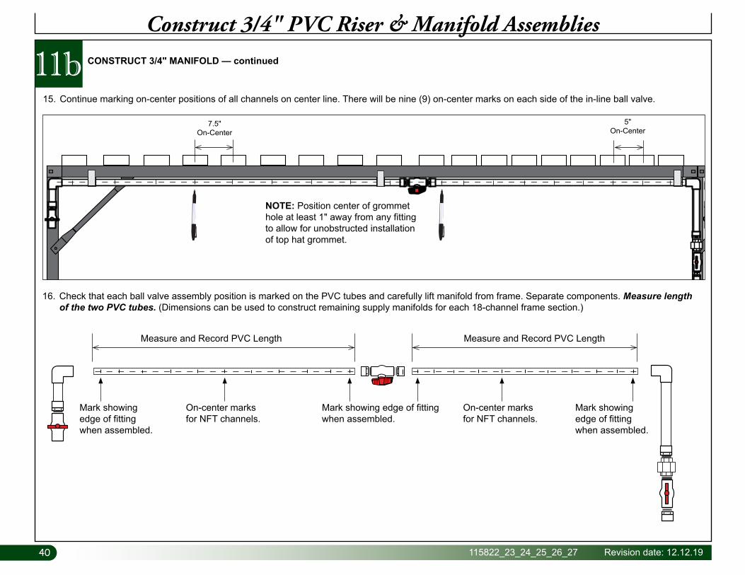
15. Continue marking on-center positions of all channels on center line. There will be nine (9) on-center marks on each side of the in-line ball valve.
16. Check that each ball valve assembly position is marked on the PVC tubes and carefully lift manifold from frame. Separate components. Measure length of the two PVC tubes. (Dimensions can be used to construct remaining supply manifolds for each 18-channel frame section.)
7.5"On-Center
5"On-Center
NOTE: Position center of grommet hole at least 1" away from any fitting to allow for unobstructed installation of top hat grommet.
Mark showing edge of fitting when assembled.
Mark showing edge of fitting when assembled.
On-center marks for NFT channels.
On-center marks for NFT channels.
Mark showing edge of fitting when assembled.
Measure and Record PVC Length Measure and Record PVC Length
41Revision date: 12.12.19 115822_23_24_25_26_27
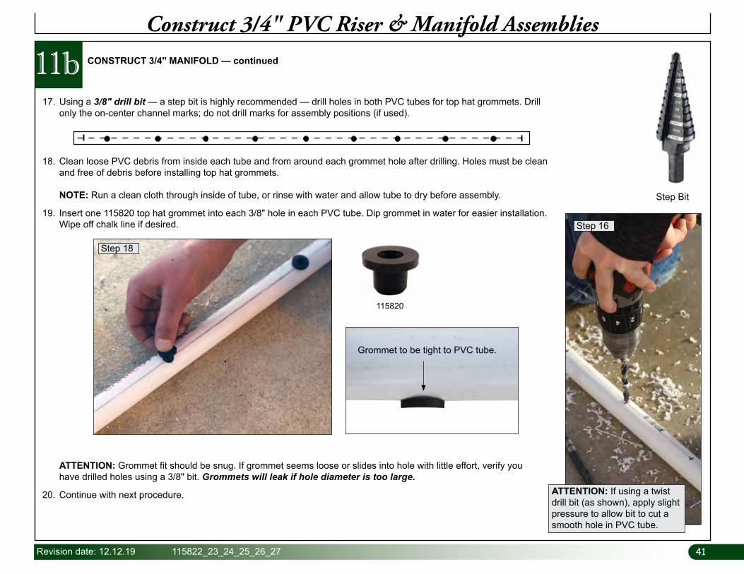
ATTENTION: If using a twist drill bit (as shown), apply slight pressure to allow bit to cut a smooth hole in PVC tube.
ATTENTION: Grommet fit should be snug. If grommet seems loose or slides into hole with little effort, verify you have drilled holes using a 3/8" bit. Grommets will leak if hole diameter is too large.
20. Continue with next procedure.
Step 16
17. Using a 3/8" drill bit — a step bit is highly recommended — drill holes in both PVC tubes for top hat grommets. Drill only the on-center channel marks; do not drill marks for assembly positions (if used).
Step Bit
11bConstruct 3/4" PVC Riser & Manifold Assemblies
CONSTRUCT 3/4" MANIFOLD — continued
18. Clean loose PVC debris from inside each tube and from around each grommet hole after drilling. Holes must be clean and free of debris before installing top hat grommets. NOTE: Run a clean cloth through inside of tube, or rinse with water and allow tube to dry before assembly.
19. Insert one 115820 top hat grommet into each 3/8" hole in each PVC tube. Dip grommet in water for easier installation. Wipe off chalk line if desired.
Grommet to be tight to PVC tube.
115820
Step 18
4242 115822_23_24_25_26_27 Revision date: 12.12.19
11cConstruct 3/4" PVC Riser & Manifold Assemblies
CONSTRUCT 3/4" MANIFOLD — continued
Final Assembly of Supply Manifold
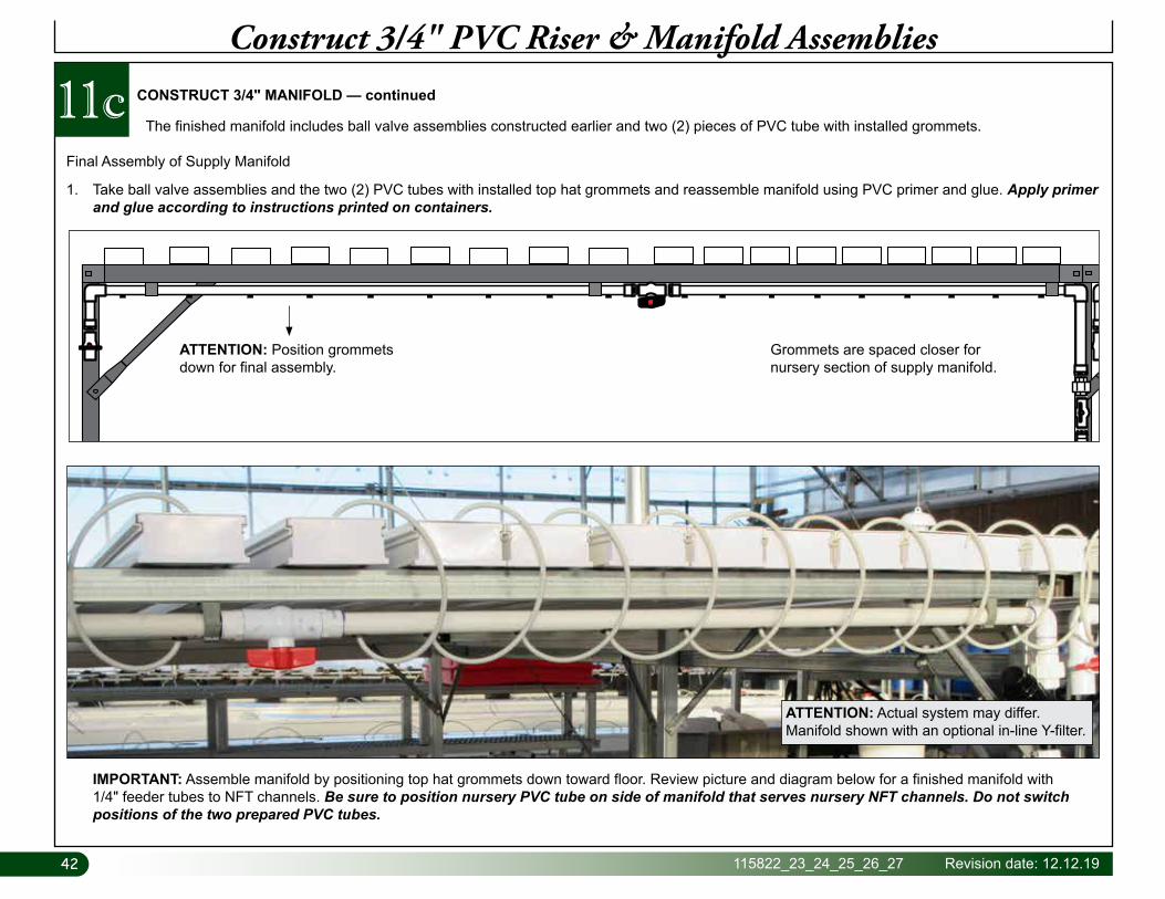
1. Take ball valve assemblies and the two (2) PVC tubes with installed top hat grommets and reassemble manifold using PVC primer and glue. Apply primer and glue according to instructions printed on containers.
The finished manifold includes ball valve assemblies constructed earlier and two (2) pieces of PVC tube with installed grommets.
ATTENTION: Position grommets down for final assembly.
Grommets are spaced closer for nursery section of supply manifold.
IMPORTANT: Assemble manifold by positioning top hat grommets down toward floor. Review picture and diagram below for a finished manifold with 1/4" feeder tubes to NFT channels. Be sure to position nursery PVC tube on side of manifold that serves nursery NFT channels. Do not switch positions of the two prepared PVC tubes.
ATTENTION: Actual system may differ. Manifold shown with an optional in-line Y-filter.
43Revision date: 12.12.19 115822_23_24_25_26_27
11cConstruct 3/4" PVC Riser & Manifold Assemblies
CONSTRUCT 3/4" MANIFOLD — continued
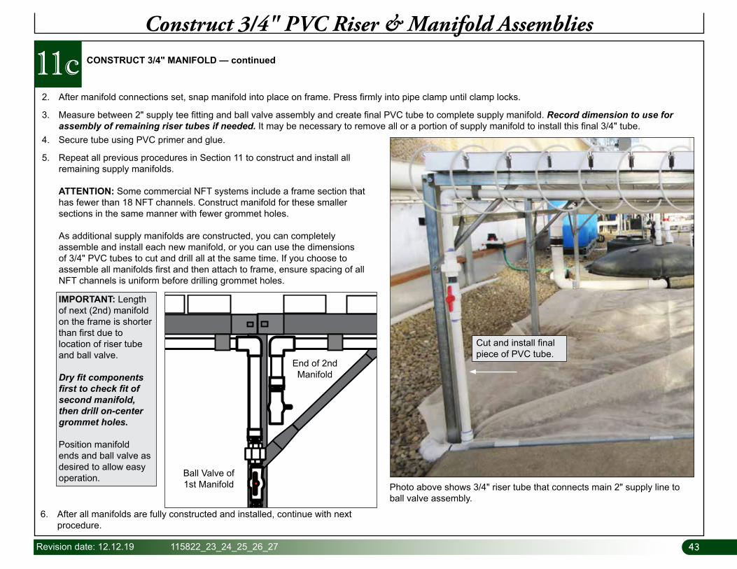
2. After manifold connections set, snap manifold into place on frame. Press firmly into pipe clamp until clamp locks.
3. Measure between 2" supply tee fitting and ball valve assembly and create final PVC tube to complete supply manifold. Record dimension to use for assembly of remaining riser tubes if needed. It may be necessary to remove all or a portion of supply manifold to install this final 3/4" tube.
4. Secure tube using PVC primer and glue.
5. Repeat all previous procedures in Section 11 to construct and install all remaining supply manifolds. ATTENTION: Some commercial NFT systems include a frame section that has fewer than 18 NFT channels. Construct manifold for these smaller sections in the same manner with fewer grommet holes. As additional supply manifolds are constructed, you can completely assemble and install each new manifold, or you can use the dimensions of 3/4" PVC tubes to cut and drill all at the same time. If you choose to assemble all manifolds first and then attach to frame, ensure spacing of all NFT channels is uniform before drilling grommet holes.
Cut and install final piece of PVC tube.
Photo above shows 3/4" riser tube that connects main 2" supply line to ball valve assembly.
6. After all manifolds are fully constructed and installed, continue with next procedure.
IMPORTANT: Length of next (2nd) manifold on the frame is shorter than first due to location of riser tube and ball valve.
Dry fit components first to check fit of second manifold, then drill on-center grommet holes.
Position manifold ends and ball valve as desired to allow easy operation. Ball Valve of
1st Manifold
End of 2nd Manifold
4444 115822_23_24_25_26_27 Revision date: 12.12.19
Required parts and tools:
• Channel Lids
• Drill and 9/32" Drill Bit
• Tape Measure and Marker
12Prepare Lids & Install 1/4" Feeder Tubes
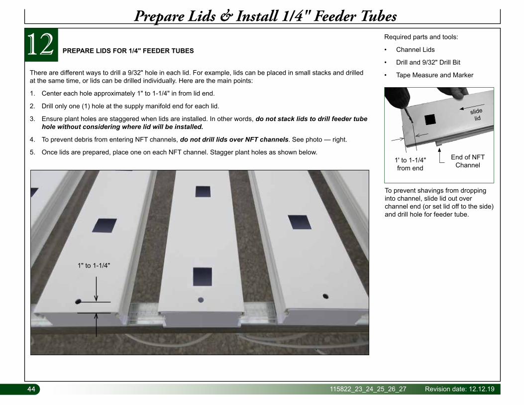
PREPARE LIDS FOR 1/4" FEEDER TUBES
There are different ways to drill a 9/32" hole in each lid. For example, lids can be placed in small stacks and drilled at the same time, or lids can be drilled individually. Here are the main points:
1. Center each hole approximately 1" to 1-1/4" in from lid end.
2. Drill only one (1) hole at the supply manifold end for each lid.
3. Ensure plant holes are staggered when lids are installed. In other words, do not stack lids to drill feeder tube hole without considering where lid will be installed.
4. To prevent debris from entering NFT channels, do not drill lids over NFT channels. See photo — right.
5. Once lids are prepared, place one on each NFT channel. Stagger plant holes as shown below.
To prevent shavings from dropping into channel, slide lid out over channel end (or set lid off to the side) and drill hole for feeder tube.
1" to 1-1/4"
slide lid
End of NFT Channel
1' to 1-1/4"from end
45Revision date: 12.12.19 115822_23_24_25_26_27
121/4" Supply Tube Installation Details
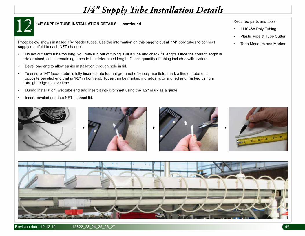
1/4" SUPPLY TUBE INSTALLATION DETAILS — continued Required parts and tools:
• 111046A Poly Tubing
• Plastic Pipe & Tube Cutter
• Tape Measure and MarkerPhoto below shows installed 1/4" feeder tubes. Use the information on this page to cut all 1/4" poly tubes to connect supply manifold to each NFT channel:
• Do not cut each tube too long; you may run out of tubing. Cut a tube and check its length. Once the correct length is determined, cut all remaining tubes to the determined length. Check quantity of tubing included with system.
• Bevel one end to allow easier installation through hole in lid.
• To ensure 1/4" feeder tube is fully inserted into top hat grommet of supply manifold, mark a line on tube end opposite beveled end that is 1/2" in from end. Tubes can be marked individually, or aligned and marked using a straight edge to save time.
• During installation, wet tube end and insert it into grommet using the 1/2" mark as a guide.
• Insert beveled end into NFT channel lid.
4646 115822_23_24_25_26_27 Revision date: 12.12.19
13Test System & Start Up
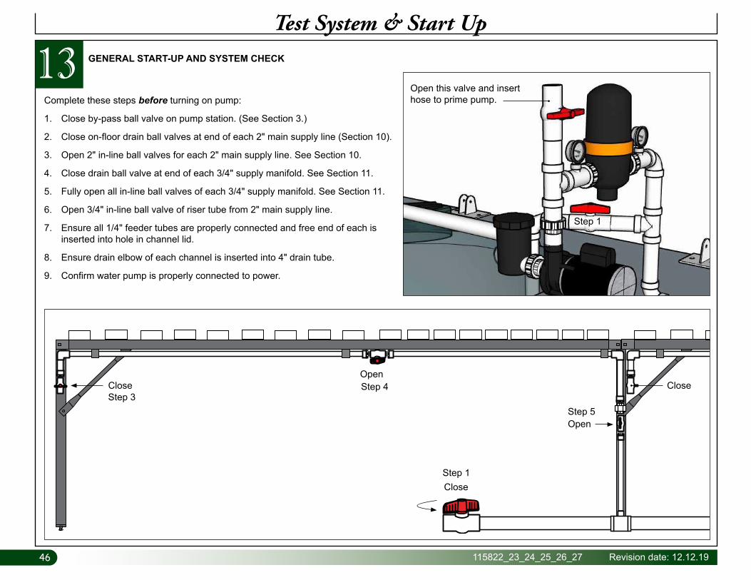
GENERAL START-UP AND SYSTEM CHECK
Complete these steps before turning on pump:
1. Close by-pass ball valve on pump station. (See Section 3.)
2. Close on-floor drain ball valves at end of each 2" main supply line (Section 10).
3. Open 2" in-line ball valves for each 2" main supply line. See Section 10.
4. Close drain ball valve at end of each 3/4" supply manifold. See Section 11.
5. Fully open all in-line ball valves of each 3/4" supply manifold. See Section 11.
6. Open 3/4" in-line ball valve of riser tube from 2" main supply line.
7. Ensure all 1/4" feeder tubes are properly connected and free end of each is inserted into hole in channel lid.
8. Ensure drain elbow of each channel is inserted into 4" drain tube.
9. Confirm water pump is properly connected to power.
Open this valve and insert hose to prime pump.
Step 1
Close
CloseStep 1
CloseStep 3
OpenStep 4
OpenStep 5
47Revision date: 12.12.19 115822_23_24_25_26_27
Complete these steps to check for water leaks, water flow, and overall proper operation:
1. Fill reservoir half full with clean water to ensure pump can run without problems.
2. Prime water pump. Open ball valve above water pump at pump station, insert water hose, and fill pipes until water reaches ball. Close the 2" in-line by-pass valve at pump station to prevent water from flowing back into tank. Close 2" ball valve above pump once water flows out. Turn on pump.
3. With pump running, inspect clear cap of filter basket. Agitated water should be visible through cap. If you cannot see water through cap, pump is not primed; turn off pump and repeat previous step to prime pump. Do not allow pump to run without pumping water.
4. Once pump is primed and water is pumping throughout the system, inspect all plumbing connections and fittings for leaks.
5. Run plain water through system for at least 30 minutes or so to ensure any debris from construction is cleaned out.
6. While fresh water is running through system, open ball valve at end of each ¾” supply manifold line (Step 3 previous page) for a couple of seconds to flush out debris.
7. Check flow rate and adjust valves at pump station to control desired flow rates through channels and back into tank. See procedure below for checking flow rate. Ideal flow rate: 400 ml to 1000 ml per minute. ATTENTION: Set flow rate as high as possible without overwhelming the 4" drain tube. A flow rate that is too great may cause the 4" drain tube to overflow during operation. See also note at lower-right.
8. Turn off pump and clean big filter at pump station periodically throughout this time to remove PVC shavings and other debris.
9. After cleaning filter, restart pump and allow to run for another 30 minutes.
10. Turn off pump and check and clean filter as needed.
13Test System & Start Up
GENERAL START-UP AND SYSTEM CHECK
Check and Set Flow Rate: Ideal Flow Rate (400 ml to 1000 ml)
1. Start pump to circulate water. Open by-pass ball valve at pump station to allow some solution to return to tank.
2. Move to an NFT channel (anywhere on the system).
3. Remove feeder tube from channel lid and insert into container for one minute.
4. After one minute, remove tube from container and measure the amount of water. Result will be flow rate per minute.
5. Check flow rate at a few other locations throughout the system to confirm.
6. Adjust ball valves as needed to set desired flow rate for entire system.
Required to check flow rate:
• Stop watch or similar timing device
• Graduated container/cylinder capable of holding up to 500 ml.
NOTE: Once system is fully populated, check flow rate periodically to ensure maximum production. A low flow rate may cause nutrient solution to meander down NFT channels; a higher flow rate forces solution to track down center of channels where plant roots are located.
48 115822_23_24_25_26_27 Revision date: 12.12.19
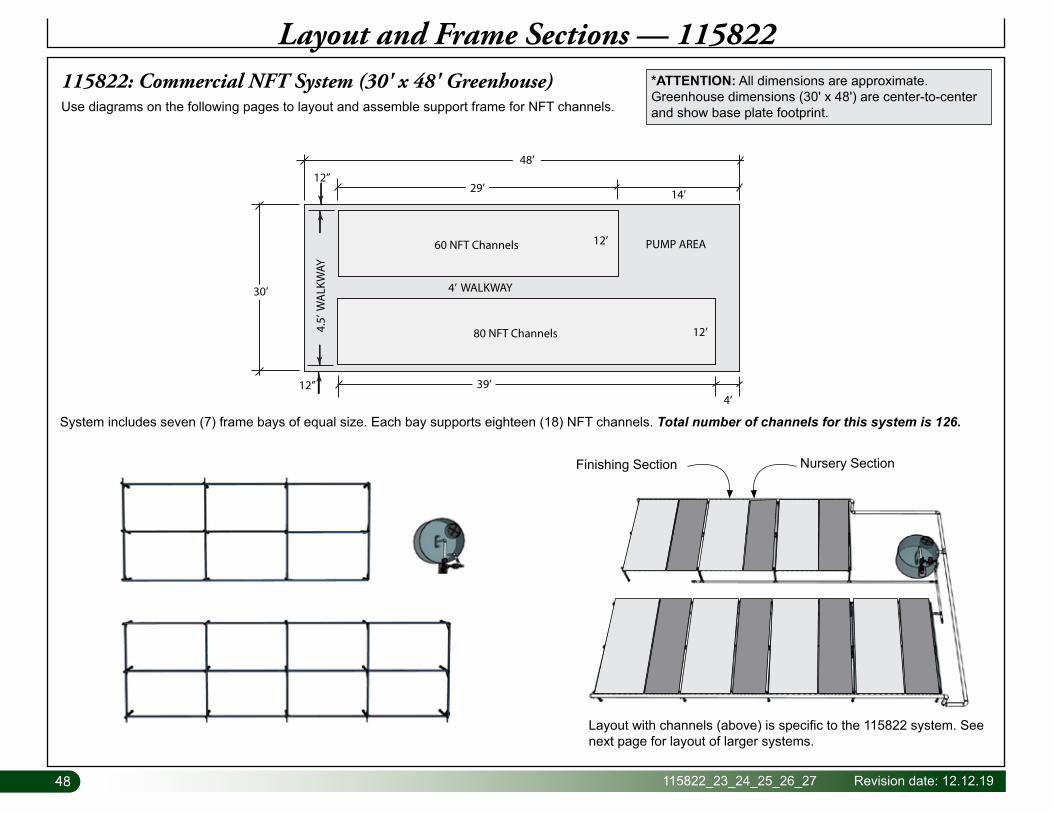
Layout and Frame Sections — 115822115822: Commercial NFT System (30' x 48' Greenhouse)
12’
14’
4’ WALKWAY
60 NFT Channels
80 NFT Channels 4.5’
WA
LKW
AY
PUMP AREA
12’
12”4’
30’
39’
29’
48’12”
*ATTENTION: All dimensions are approximate. Greenhouse dimensions (30' x 48') are center-to-center and show base plate footprint.Use diagrams on the following pages to layout and assemble support frame for NFT channels.
System includes seven (7) frame bays of equal size. Each bay supports eighteen (18) NFT channels. Total number of channels for this system is 126.
Layout with channels (above) is specific to the 115822 system. See next page for layout of larger systems.
Nursery SectionFinishing Section
49Revision date: 12.12.19 115822_23_24_25_26_27
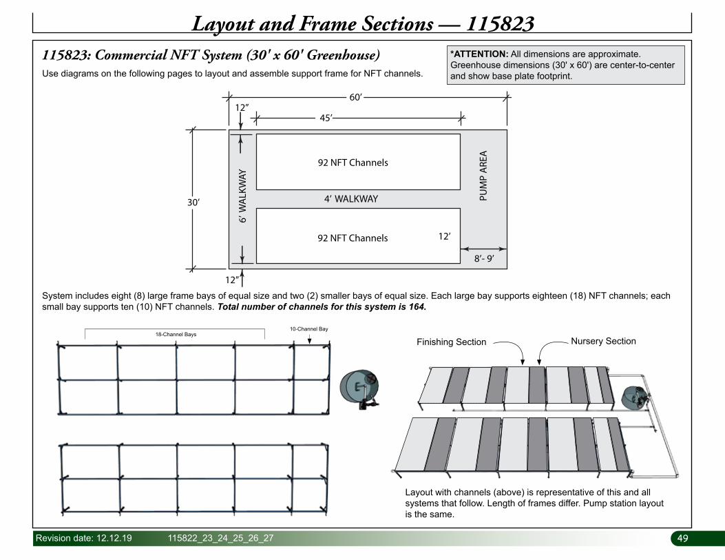
115823: Commercial NFT System (30' x 60' Greenhouse)
Layout and Frame Sections — 115823
4’ WALKWAY
92 NFT Channels
92 NFT Channels 6’
WA
LKW
AY12’
30’
12”
60’
PUM
P A
REA
8’- 9’
45’12”
*ATTENTION: All dimensions are approximate. Greenhouse dimensions (30' x 60') are center-to-center and show base plate footprint.Use diagrams on the following pages to layout and assemble support frame for NFT channels.
18-Channel Bays10-Channel Bay
System includes eight (8) large frame bays of equal size and two (2) smaller bays of equal size. Each large bay supports eighteen (18) NFT channels; each small bay supports ten (10) NFT channels. Total number of channels for this system is 164.
Layout with channels (above) is representative of this and all systems that follow. Length of frames differ. Pump station layout is the same.
Nursery SectionFinishing Section

50 115822_23_24_25_26_27 Revision date: 12.12.19
115824: Commercial NFT System (30' x 72' Greenhouse)
Layout and Frame Sections — 115824
12’
4’ WALKWAY
6’ W
ALK
WAY
12’
30’
12”
12”72’
55’
PUM
P A
REA
112 NFT Channels
112 NFT Channels 11’
*ATTENTION: All dimensions are approximate. Greenhouse dimensions (30' x 72') are center-to-center and show base plate footprint.Use diagrams on the following pages to layout and assemble support frame for NFT channels.
System includes ten (10) large frame bays of equal size and two (2) smaller bays of equal size. Each large bay supports eighteen (18) NFT channels; each small bay supports ten (10) NFT channels. Total number of channels for this system is 200.
18-Channel Bays 10-Channel Bay
51Revision date: 12.12.19 115822_23_24_25_26_27
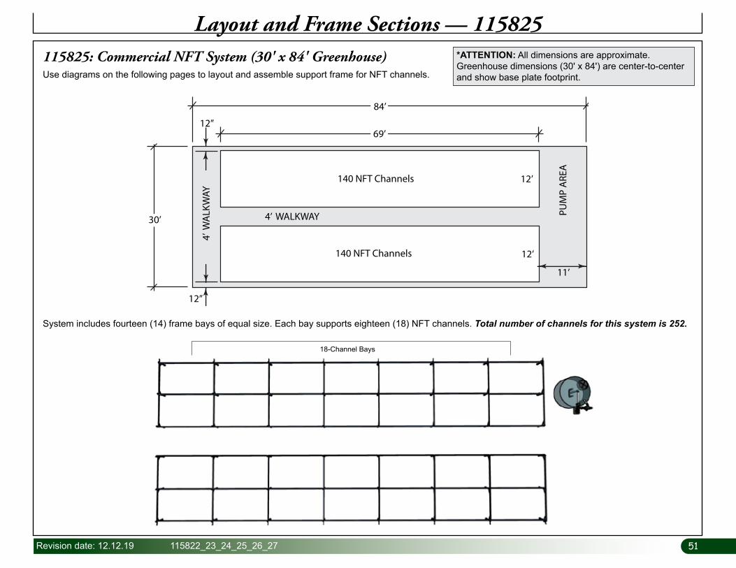
115825: Commercial NFT System (30' x 84' Greenhouse)
Layout and Frame Sections — 115825
84’
4’ WALKWAY4’
WA
LKW
AY
12’
12’
30’
PUM
P A
REA
140 NFT Channels
140 NFT Channels
69’
11’
12”
12”
*ATTENTION: All dimensions are approximate. Greenhouse dimensions (30' x 84') are center-to-center and show base plate footprint.Use diagrams on the following pages to layout and assemble support frame for NFT channels.
System includes fourteen (14) frame bays of equal size. Each bay supports eighteen (18) NFT channels. Total number of channels for this system is 252.
18-Channel Bays
52 115822_23_24_25_26_27 Revision date: 12.12.19
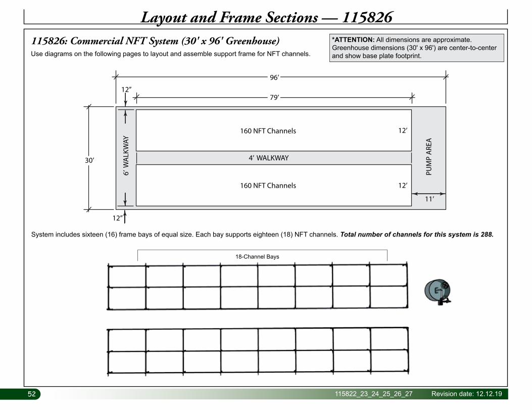
115826: Commercial NFT System (30' x 96' Greenhouse)
Layout and Frame Sections — 115826
12’
96’
4’ WALKWAY
6’ W
ALK
WAY
12’
30’
PUM
P A
REA
79’
160 NFT Channels
160 NFT Channels
12”
12”
11’
Use diagrams on the following pages to layout and assemble support frame for NFT channels.
*ATTENTION: All dimensions are approximate. Greenhouse dimensions (30' x 96') are center-to-center and show base plate footprint.
18-Channel Bays
System includes sixteen (16) frame bays of equal size. Each bay supports eighteen (18) NFT channels. Total number of channels for this system is 288.
53Revision date: 12.12.19 115822_23_24_25_26_27
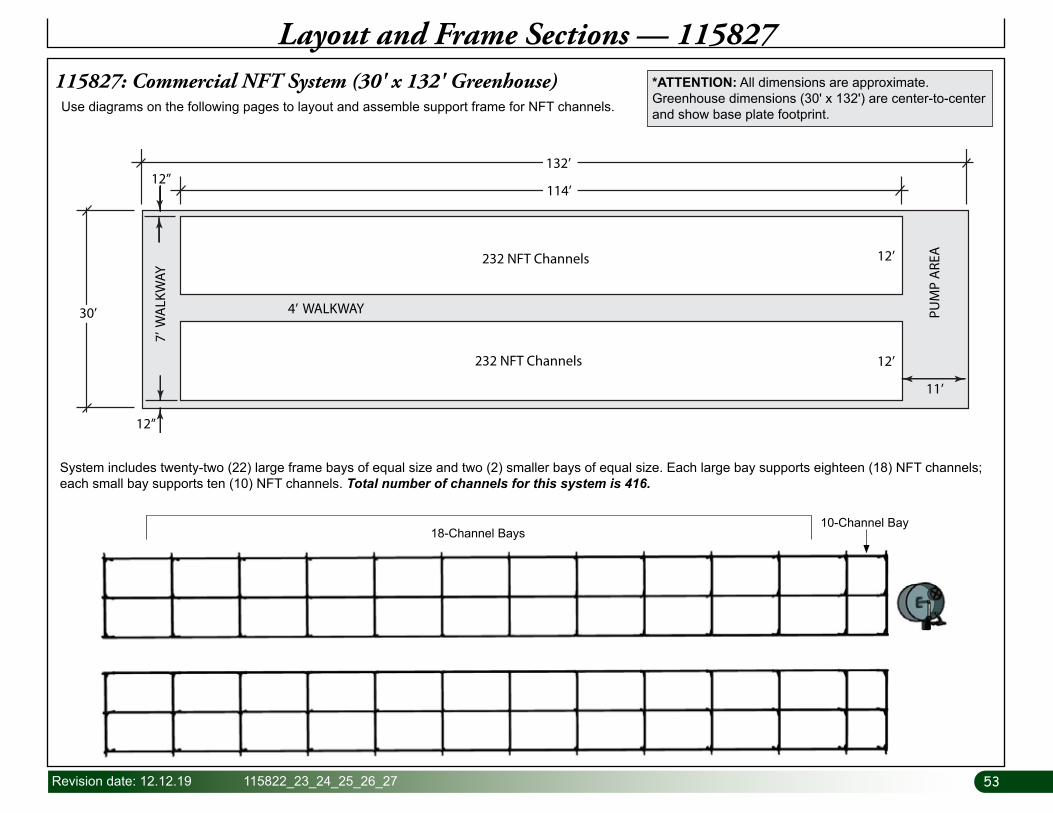
115827: Commercial NFT System (30' x 132' Greenhouse)
Layout and Frame Sections — 115827
12’
4’ WALKWAY
7’ W
ALK
WAY
12’
30’
132’
114’
PUM
P A
REA
11’
232 NFT Channels
232 NFT Channels
12”
12”
Use diagrams on the following pages to layout and assemble support frame for NFT channels.
*ATTENTION: All dimensions are approximate. Greenhouse dimensions (30' x 132') are center-to-center and show base plate footprint.
18-Channel Bays10-Channel Bay
System includes twenty-two (22) large frame bays of equal size and two (2) smaller bays of equal size. Each large bay supports eighteen (18) NFT channels; each small bay supports ten (10) NFT channels. Total number of channels for this system is 416.
54 115822_23_24_25_26_27 Revision date: 12.12.19
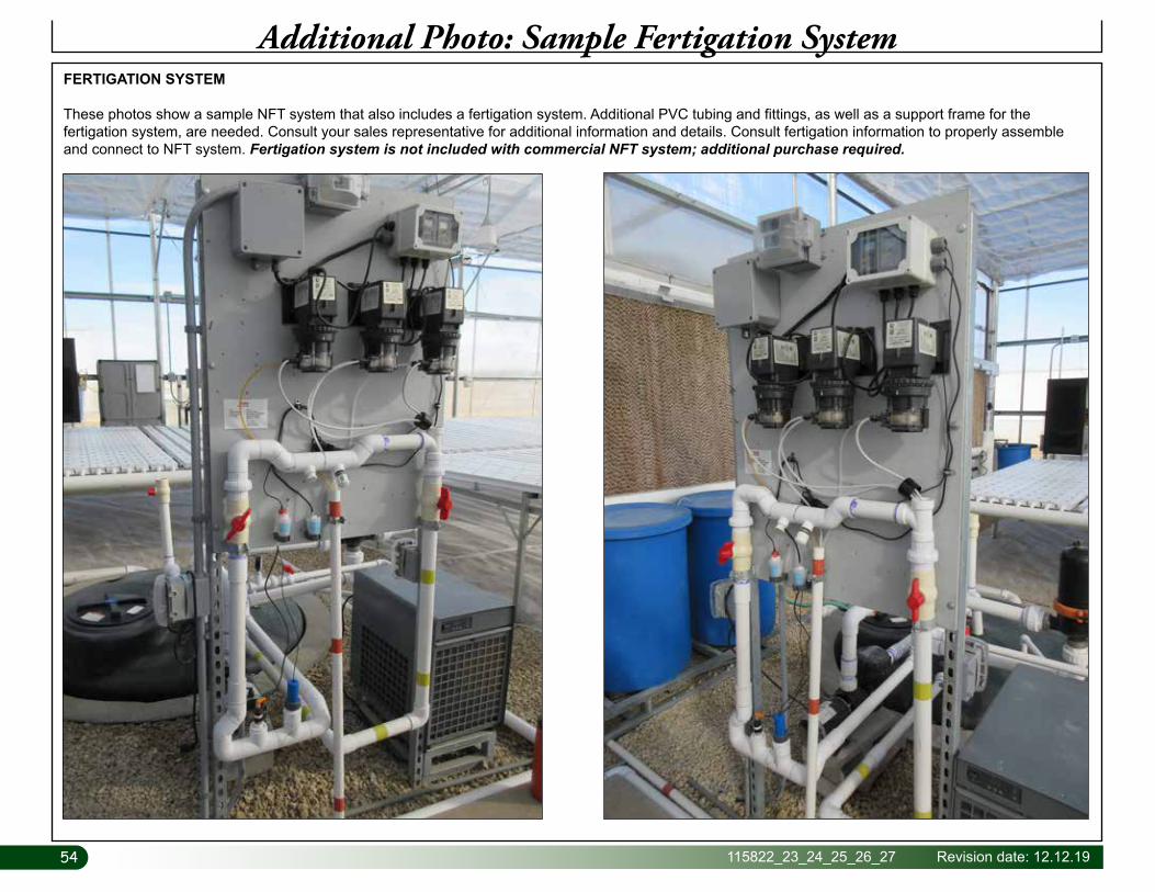
Additional Photo: Sample Fertigation SystemFERTIGATION SYSTEM
These photos show a sample NFT system that also includes a fertigation system. Additional PVC tubing and fittings, as well as a support frame for the fertigation system, are needed. Consult your sales representative for additional information and details. Consult fertigation information to properly assemble and connect to NFT system. Fertigation system is not included with commercial NFT system; additional purchase required.
55Revision date: 12.12.19 115822_23_24_25_26_27
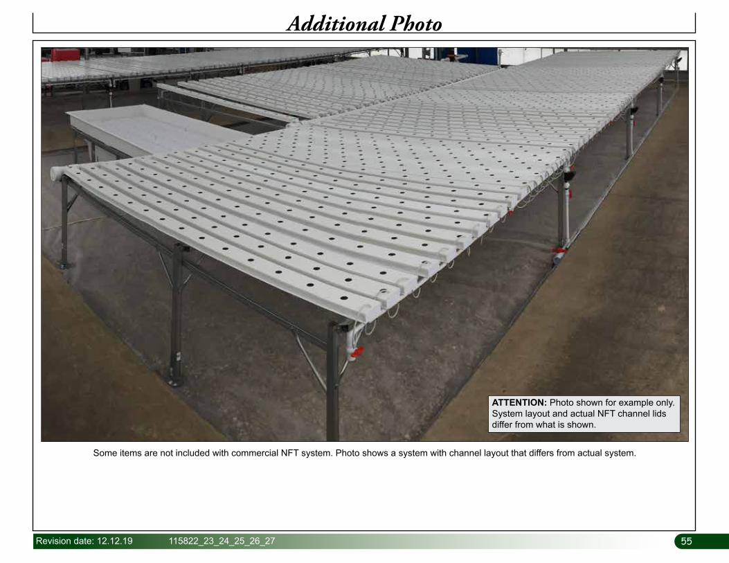
Additional Photo
Some items are not included with commercial NFT system. Photo shows a system with channel layout that differs from actual system.
ATTENTION: Photo shown for example only. System layout and actual NFT channel lids differ from what is shown.