Embed Size (px)
Citation preview
HYDROCAL 1009 Multi-Gas-in-Oil Analysis System with Transformer Monitoring Functions
The HYDROCAL 1009 is a permanently installed multi-gas-in-oil analysis system with transformer monitoring functions. It individu-ally measures, Moisture in Oil (H2O) and the key gases Hydrogen (H2), Carbon Monoxide (CO), Carbon Dioxide (CO2), Methane (CH4), Acetylene (C2H2), Ethylene (C2H4), Ethane (C2H6) and Oxy-gen (O2) dissolved in transformer oil.
As Hydrogen (H2) is involved in nearly every fault of the insulation system of power transformers and Carbon Monoxide (CO) is a sign of an involvement of the cellulosic / paper insulation the presence and increase of Acetylene (C2H2) and Ethylene (C2H4) further clas-sifies the nature of a fault as overheating, partial discharge or high energy arcing. Oxygen (O2) can be a sign of excessive ageing or leakages within the sealing of hermetic transformers.
The device can serve as a compact transformer monitoring system by the integration / connection of other sensors present on a trans-former via its optional analog inputs:
4 Analog inputs 0/4 ... 20mADC
6 Analog inputs 0/4 ... 20mAAC +20% or 0 ... 80 VAC +20% (configurable by jumpers)
Key Advantages
Individual measurement of Hydrogen (H2), Carbon Monoxide (CO), Carbon Dioxide (CO2), Methane (CH4), Acetylene (C2H2), Ethylene (C2H4), Ethane (C2H6) and Oxygen (O2)
Moisture in Oil (H2O) measurement Easy to mount on a transformer valve
(G 1½" DIN ISO 228-1 or 1½" NPT ANSI B 1.20.1) Installation on the operational transformer without any opera-
tional interruption Advanced software (on the unit and via PC)
Maintenance free system
Communication interfaces ETHERNET 10/100 Mbit/s (copper-wired / RJ 45 or fibre-optical / SC Duplex) and RS 485 to sup-
port MODBUS®RTU/ASCII, MODBUSTCP, DNP3 proprietary communication and IEC 61850 protocols
Optional on-board GSM or analog modem for remote access
Optional DNP3 serial modem for SCADA connection
Optional IEC 61850 modem for SCADA connection
Optional HV and LV bushing sensors for HV and LV bushing monitoring applications via communication interface
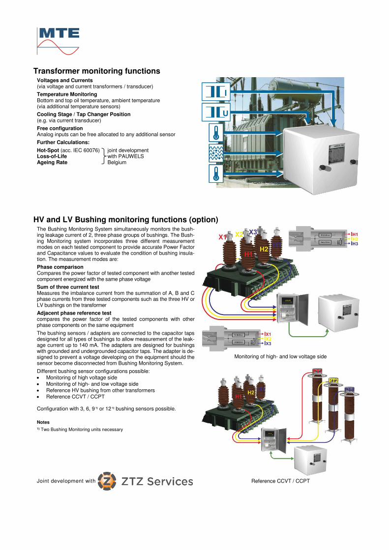
Transformer monitoring functions Voltages and Currents (via voltage and current transformers / transducer)
Temperature Monitoring Bottom and top oil temperature, ambient temperature (via additional temperature sensors)
Cooling Stage / Tap Changer Position (e.g. via current transducer)
Free configuration Analog inputs can be free allocated to any additional sensor
Further Calculations:
Hot-Spot (acc. IEC 60076) joint development Loss-of-Life with PAUWELS Ageing Rate Belgium
HV and LV Bushing monitoring functions (option) The Bushing Monitoring System simultaneously monitors the bush-ing leakage current of 2, three phase groups of bushings. The Bush-ing Monitoring system incorporates three different measurement modes on each tested component to provide accurate Power Factor and Capacitance values to evaluate the condition of bushing insula-tion. The measurement modes are:
Phase comparison Compares the power factor of tested component with another tested component energized with the same phase voltage
Sum of three current test Measures the imbalance current from the summation of A, B and C phase currents from three tested components such as the three HV or LV bushings on the transformer
Adjacent phase reference test compares the power factor of the tested components with other phase components on the same equipment
The bushing sensors / adapters are connected to the capacitor taps designed for all types of bushings to allow measurement of the leak-age current up to 140 mA. The adapters are designed for bushings with grounded and undergrounded capacitor taps. The adapter is de-signed to prevent a voltage developing on the equipment should the sensor become disconnected from Bushing Monitoring System.
Monitoring of high- and low voltage side
Different bushing sensor configurations possible:
Monitoring of high voltage side
Monitoring of high- and low voltage side
Reference HV bushing from other transformers
Reference CCVT / CCPT Configuration with 3, 6, 9 1) or 12 1) bushing sensors possible.
Notes
1) Two Bushing Monitoring units necessary
Joint development with
Reference CCVT / CCPT
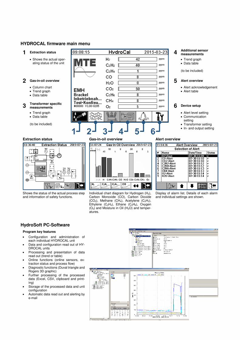
HYDROCAL firmware main menu
1 Extraction status
4 Additional sensor measurements
Shows the actual oper-ating status of the unit
Trend graph
Data table (to be included)
2 Gas-in-oil overview 5 Alert overview
Column chart
Trend graph
Data table
Alert acknowledgement
Alert table
3 Transformer specific measurements 6 Device setup
Trend graph
Data table (to be included)
Alert level setting
Communication setting
Transformer setting
In- and output setting
Extraction status Gas-in-oil overview Alert overview
Shows the status of the actual process step and information of safety functions.
Individual chart diagram for Hydrogen (H2), Carbon Monoxide (CO), Carbon Dioxide (CO2), Methane (CH4), Acetylene (C2H2), Ethylene (C2H4), Ethane (C2H6), Oxygen (O2) and Moisture in Oil (H2O) and temper-atures.
Display of alarm list. Details of each alarm and individual settings are shown.
HydroSoft PC-Software
Program key features
Configuration and administration of each individual HYDROCAL unit
Data and configuration read out of HY-DROCAL units
Processing and presentation of data read out (trend or table)
Online functions (online sensors, ex-traction status and process flow)
Diagnostic functions (Duval triangle and Rogers 3D graphic)
Further processing of the processed data (Excel, CSV, clipboard and print-ing)
Storage of the processed data and unit configuration
Automatic data read out and alerting by e-mail
Edition 10.2015
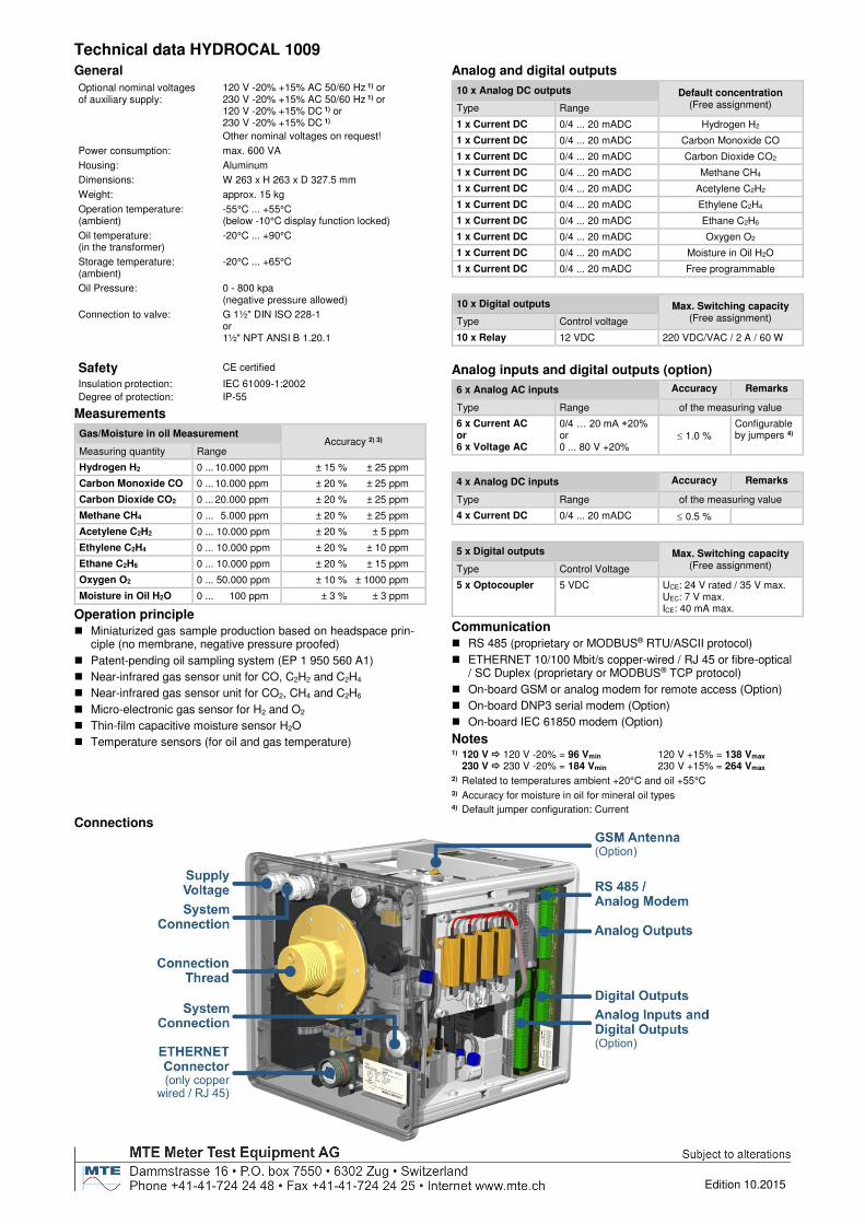
Technical data HYDROCAL 1009
General
Optional nominal voltages of auxiliary supply:
120 V -20% +15% AC 50/60 Hz 1) or 230 V -20% +15% AC 50/60 Hz 1) or 120 V -20% +15% DC 1) or 230 V -20% +15% DC 1)
Other nominal voltages on request!
Power consumption: max. 600 VA
Housing: Aluminum
Dimensions: W 263 x H 263 x D 327.5 mm
Weight: approx. 15 kg
Operation temperature: (ambient)
-55°C ... +55°C (below -10°C display function locked)
Oil temperature: (in the transformer)
-20°C ... +90°C
Storage temperature: (ambient)
-20°C ... +65°C
Oil Pressure: 0 - 800 kpa (negative pressure allowed)
Connection to valve: G 1½" DIN ISO 228-1 or 1½" NPT ANSI B 1.20.1
Safety CE certified
Insulation protection: IEC 61009-1:2002
Degree of protection: IP-55
Measurements
Gas/Moisture in oil Measurement Accuracy 2) 3)
Measuring quantity Range
Hydrogen H2 0 ... 10.000 ppm ± 15 % ± 25 ppm
Carbon Monoxide CO 0 ... 10.000 ppm ± 20 % ± 25 ppm
Carbon Dioxide CO2 0 ... 20.000 ppm ± 20 % ± 25 ppm
Methane CH4 0 ... 5.000 ppm ± 20 % ± 25 ppm
Acetylene C2H2 0 ... 10.000 ppm ± 20 % ± 5 ppm
Ethylene C2H4 0 ... 10.000 ppm ± 20 % ± 10 ppm
Ethane C2H6 0 ... 10.000 ppm ± 20 % ± 15 ppm
Oxygen O2 0 ... 50.000 ppm ± 10 % ± 1000 ppm
Moisture in Oil H2O 0 ... 100 ppm ± 3 % ± 3 ppm
Operation principle
Miniaturized gas sample production based on headspace prin-ciple (no membrane, negative pressure proofed)
Patent-pending oil sampling system (EP 1 950 560 A1)
Near-infrared gas sensor unit for CO, C2H2 and C2H4
Near-infrared gas sensor unit for CO2, CH4 and C2H6
Micro-electronic gas sensor for H2 and O2
Thin-film capacitive moisture sensor H2O
Temperature sensors (for oil and gas temperature)
Analog and digital outputs
10 x Analog DC outputs Default concentration (Free assignment) Type Range
1 x Current DC 0/4 ... 20 mADC Hydrogen H2
1 x Current DC 0/4 ... 20 mADC Carbon Monoxide CO
1 x Current DC 0/4 ... 20 mADC Carbon Dioxide CO2
1 x Current DC 0/4 ... 20 mADC Methane CH4
1 x Current DC 0/4 ... 20 mADC Acetylene C2H2
1 x Current DC 0/4 ... 20 mADC Ethylene C2H4
1 x Current DC 0/4 ... 20 mADC Ethane C2H6
1 x Current DC 0/4 ... 20 mADC Oxygen O2
1 x Current DC 0/4 ... 20 mADC Moisture in Oil H2O
1 x Current DC 0/4 ... 20 mADC Free programmable
10 x Digital outputs Max. Switching capacity (Free assignment) Type Control voltage
10 x Relay 12 VDC 220 VDC/VAC / 2 A / 60 W
Analog inputs and digital outputs (option)
6 x Analog AC inputs Accuracy Remarks
Type Range of the measuring value
6 x Current AC or 6 x Voltage AC
0/4 … 20 mA +20% or 0 ... 80 V +20%
1.0 %
Configurable by jumpers 4)
4 x Analog DC inputs Accuracy Remarks
Type Range of the measuring value
4 x Current DC 0/4 ... 20 mADC 0.5 %
5 x Digital outputs Max. Switching capacity (Free assignment) Type Control Voltage
5 x Optocoupler 5 VDC UCE: 24 V rated / 35 V max. UEC: 7 V max. ICE: 40 mA max.
Communication
RS 485 (proprietary or MODBUS® RTU/ASCII protocol)
ETHERNET 10/100 Mbit/s copper-wired / RJ 45 or fibre-optical / SC Duplex (proprietary or MODBUS® TCP protocol)
On-board GSM or analog modem for remote access (Option)
On-board DNP3 serial modem (Option)
On-board IEC 61850 modem (Option)
Notes 1) 120 V 120 V -20% = 96 Vmin 120 V +15% = 138 Vmax
230 V 230 V -20% = 184 Vmin 230 V +15% = 264 Vmax 2) Related to temperatures ambient +20°C and oil +55°C 3) Accuracy for moisture in oil for mineral oil types 4) Default jumper configuration: Current
Connections


![[MS-RDPECLIP]: Remote Desktop Protocol: Clipboard … · Remote Desktop Protocol: Clipboard Virtual Channel ... Remote Desktop Protocol: Clipboard Virtual ... Remote Desktop Protocol:](https://img.pdfslide.us/doc/110x75/5ae3205b7f8b9a097a8dc1a3/ms-rdpeclip-remote-desktop-protocol-clipboard-desktop-protocol-clipboard.jpg)