Embed Size (px)
Citation preview

Recreational Spas
Installation and Owner’s Manual
C
TABLE OF CONTENTS
• Your Spa and Dealer Information page 3 • Important Safety Instructions pages 4-6 • Installation Procedures pages 6-7 • Electrical Specifications (Power Requirements) pages 8-9 • CS6200 Control Box Power Switch Diagram page 10 • CS6200 Control System VDS System page 11 • Operation Procedures (Start Up Preparation) page 12 • Draining Your Spa page 13 • Operating Top Side Control page 13-14 • Programming Filtration page 14 • Additional Features page 15 • Ozone Generator Safety Instructions page 16 • Filter Assembly and Parts page 16 • Spa Serial Number Location page 17 • Maintenance and Care page 17-18 • Your Cabinet and Cedar Skirting page 18-19 • Chemicals page 19-21 • Chemical Trouble Shooting Guide page 21 • Top Side Error Identification pages21-22 • Basic Troubleshooting pages22-24 • Warranty page 25
.
Manufacturer Reserves The Right To Change Specifications Without Notice.
Part# 7229
Manufacturer of Fine Spas 13055 49th ST. N.
Clearwater, Florida 33762 (727) 573-9611 Fax (727) 573-7758
2

www.HYDROSPA.com
YOUR SPA and DEALER
MONTE CARLO
SAN MARCO SIESTA VENICE
INFORMATION CONERNING YOUR NEW SPA (Please take this time to fill out the information below along with your Dealer) Complete the Warranty Registration Card on the back, and mail it to Hydro Spa with-in 90 Days, or complete your Warranty Registration on-line at http://www.hydrospa.com. Thank you for your purchase of a quality spa manufactured by Hydro Spa, 1-800-BEST-SPA.
Spa Name/Model:
Spa Serial Number: 8 Digit Number
Spa Color:
Date Of Purchase: MM/DD/YY
Dealer/Store Name:
Dealer/Store Address:
Dealer/Store City:
Dealer/Store State:
Dealer/Store Zip:
3

IMPORTANT SAFETY INSTRUCTIONS
When installing your SPA and using this electrical equipment, basic safety precautions should always be followed, to include the following:
• READ AND FOLLOW ALL INSTRUCTIONS! The following instructions are required by ETL to be printed as a condition of their listing this product. They contain important safety information we strongly urge you to read and apply.
• DANGER - TO REDUCE THE RISK OF INJURY: Do not permit children to use spa unless they are closely supervised at all times.
Thmuim
•
•
C
WARNING SIGN MUST BE POSTED e WARNING sign (RED) above is packed with your Hydro Spa. This sign st be posted in a prominent place in close proximity to the spa installation site
mediately upon completion of spa installation.
WARNING SIGN - It is extremely important that this sign be permanently placed in clear view of any persons using the spa. Occasional spa users may not be aware of some of the dangers hot water poses to pregnant women, small children, and people under the influence of alcohol. If you did not receive a warning sign or your sign has become damaged, please contact your spa dealer or the manufacturer. DANGER - A wire connector is provided on this unit to connect a minimum No. 8 AWG (8.4mm2) solid copper conductor between unit and any metal equipment, metal enclosures of electrical equipment, metal water pipe, or conduit, if that item is located within 5 feet (1.5m) of the unit.
4
• DANGER - RISK Of ACCIDENTAL DROWNING: Extreme Caution must be exercised at all times, to prevent unauthorized access by children. To avoid accidents, ensure that children cannot use spa unless they are supervised at all times.
• DANGER - TO REDUCE THE RISK OF INJURY: The suction fittings is the spa are sized to match the specific water flow created by the pump. Should the need arise to replace the suction fittings or the pump, be sure that the flow rates are compatible.
• DANGER - RISK OF ELECTRICAL SHOCK:. Install at least 6 feet (91.5m) from all metal surfaces. As an alternative, a spa may be installed within 5 feet of metal surfaces if each metal surface is permanently connected by a minimum No. 8 AWG (8.4mm2) solid copper conductor to the wire connector on the terminal box that is provided for this purpose.
• DANGER - RISK OF ELECTRICAL SHOCK: Do not permit any electrical appliance, such as a light, telephone, radio or television within 5 feet (1.5m) of the spa.
• Position spa to provide proper drainage of the compartment for electrical components.
• For floor recessed spas, install to permit access for servicing from above or below floor.
• NEVER USE AN EXTENSION CORD! • Consideration should be taken for water splash out. Water can ruin wood floors
and some finishes. • DO NOT use a wall switch, ground fault circuit interrupter, circuit breaker, fuse,
or plugging and unplugging the spa as a means of turning on or off your spa for normal everyday use.
• DO NOT block access door. • Set the spa on a firm level (flat) surface. Do not set spa on blocks as structural
damage may occur to spa.
WHILE USING SPA, FOLLOWING ALL THESE SAFETY PRECAUTIONS 1. WARNING – To reduce the risk of injury. The water in a spa should never exceed
40 o C (104 o F). Water temperatures between 38 o C (100 o F) and 40 o C (104 o F) are considered safe for a healthy adult. Lower water temperatures are recommended for young children and when spa use exceeds 10 minutes. Since excessive water temperatures have a high potential for causing fetal damage during early pregnancy, pregnant or possibly pregnant women should limit water temperatures to 38 o C (100 o F). Before entering a spa, the user should measure the water temperature with an accurate thermometer. (The tolerances of water temperature-regulating devices vary.) The use of alcohol, drugs, or medication before or during spa use may lead to unconsciousness with the possibility of drowning. Persons suffering from obesity, medical history of heart disease, low/high blood pressure, circulatory system problems, or diabetes, should consult a physician before using a spa. Persons using medication should consult a physician before using a spa
5
because some medications induce drowsiness while others may affect heart rate, blood pressure, and circulation.
2. DANGER – Prolonged immersion in hot water may induce hypothermia. The causes, symptoms and effects of hypothermia may be described as follows: Hypothermia occurs when the internal temperature of the body reaches a level several degrees above the normal body temperature of 98.6 o F. The symptoms of hypothermia include:
• Failure to perceive heat • Failure to recognize the need to exit spa or hot tub • Unawareness of impending hazard • Fetal damage in pregnant women • Physical inability to exit the spa or hot tub • Unconsciousness resulting in the danger of drowning
WARNING – THE USE OF ALCOHOL, DRUGS OR MEDICATION CAN
GREATLY INCREASE THE RISK OF FATAL HYPOTHERMIA.
3. DO NOT JUMP OR DIVE INTO SPA.
SAVE THESE INSTRUCTIONS!
INSTALLATION
The installation of your spa is not included in the cost the spa unless specifically noted on your invoice by your dealer. Planning Your Installation Proper planning is an important consideration when installing your new spa. Site selection is a critical step and should be given some serious thought. Planning ahead, before the delivery of your spa, will make the process of installation easier. The following information is provided to assist you in site preparations. General Check out the local building codes with respects to gates, fences etc. Be sure that the spa will have proper access to water, drainage and electrical. The spa must have proper support underneath to support the weight. In most cases, the best answer is a 4-inch thick cement pad. However, there are many ways to support your spa. Please consult your spa sales representative before constructing a base that will be right for your needs.
6

Indoor Installations Be sure your spa will fit into the space you have chosen. Proper access into the home is needed to move the spa into place. Ventilation may be needed because of the humidity from the spa. In most cases, a Spa Cover is sufficient. Be sure to check the load carrying capabilities of the floor you will be installing your spa, as most homes meet the requirement of 125lbs per square foot. Insure you have proper drainage in the event of a leak. Outdoor Installations Assure that spa is on a flat level surface. Never put spa on blocks! If the spa is not supported evenly over the entire bottom surface, structural damage will occur. Protect pump and equipment from the weather (Keep access panel door closed at all times). Assure access to spa’s service door, filter, entry and power connection. Solid Load Bearing Site The site must provide a solid foundation with a minimum load bearing capacity of 90 lbs per sq. ft. Concrete slabs and decks must be designed to support this weight. Do not select a site composed of individual unsupported bricks, blocks or other materials, which will shift unevenly and cause damage to your spas internal frame. Level Site, Flat Surface A level site is critical to both the performance and enjoyment of your spa. Water is unforgiving and will always settle level. A flat and level site provides the surface necessary to properly dispense weight between the foot-well, which bears most of the spa’s weight and the structural frame, which primarily provides stabilization and secondary support. The importance proper of support for the foot well in conjunction with spa cabinet cannot be over stressed.
ELECTRICAL SPECIFICATIONS
ELECTRICAL SPECIFICATIONS
7
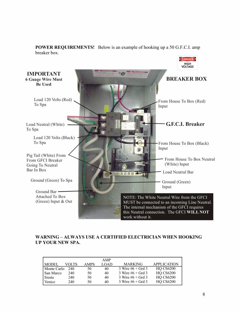
POWER REQUIREMENTS! Below is an example of hooking up a 50 G.F.C.I. amp breaker box.
Load 120 Volts (Black)To Spa
Load 120 Volts (Red)To Spa
Load Neutral (White)To Spa
IMPORTANT6 Guage Wire Must
Be Used
Pig Tail (White) FromFrom GFCI BreakerGoing To NeutralBar In Box
Ground (Green) To Spa
Ground BarAttached To Box(Green) Input & Out
From House To Box (Red)Input
From House To Box (Black)Input
Load Neutral Bar
From House To Box Neutral(White) Input
Ground (Green)Input
BREAKER BOX
G.F.C.I. Breaker
NOTE: The White Neutral Wire from the GFCIMUST be connected to an incoming Line Neutral. The internal mechanism of the GFCI requires this Neutral connection. The GFCI work without it.
WILL NOT
WARNING – ALWAYS USE A CERTIFIED ELECTRICIAN WHEN HOOKING UP YOUR NEW SPA.
MODELMonte CarloSan MarcoSiestaVenice
VOLTS240240240240
AMPS50505050
AMP LOAD
40404040
MARKING3 Wire #6 + Grd 3 333
Wire #6 + Grd 3 Wire #6 + Grd 3 Wire #6 + Grd 3
APPLICATIONHQ CS6200HQ CS6200HQ CS6200HQ CS6200
8
An illustration showing the proper electrical connections for 240 volt service has been provided for you on a wiring diagram and conversion instruction affixed to the backside of the electrical box faceplate. GFCI wiring instructions you can find on the backside of the electrical box too. Be sure to follow these and all other instructions carefully. Be sure that all connections are tight before switching on the circuit breaker. CAUTION! Failure to abide by specification listed may result in damage to equipment and may void the warranty. IF THE SPA IS WIRED INCORRECTLY, YOUR WARRANTY WILL BE VOID ON ANY BURNED OUT ELECTRICAL EQUIPMENT.
G.F.C.I Line-out Wiring Check for 120/240V convertible System (3/4 wire system including ground wire). If the spa is equipped with a 120/240V control system, an additional white load neutral wire must connect to the load neutral out. This wire runs with the others to the system box. Proper placement of this neutral wire is essential. If miss-wired, the G.F.C.I will trip. G.F.C.I (Ground Fault Circuit Interrupter) IMPORTANT This service must be single phase. Do not attempt to fix these types of problems yourself. High voltage can seriously injure or kill. Always use a certified electrician when hooking up your new spa. The National Electrical Code states that a service disconnect breaker box (a G.F.C.I. can be used for this purpose) must be located at least 5 feet away from the spa and should be conveniently located near the equipment bay. If it is not in plain sight, keep the disconnect padlocked when in the off position. Remember, high voltage is still accessible in the housebreaker box even though you have turned off the spa breaker.
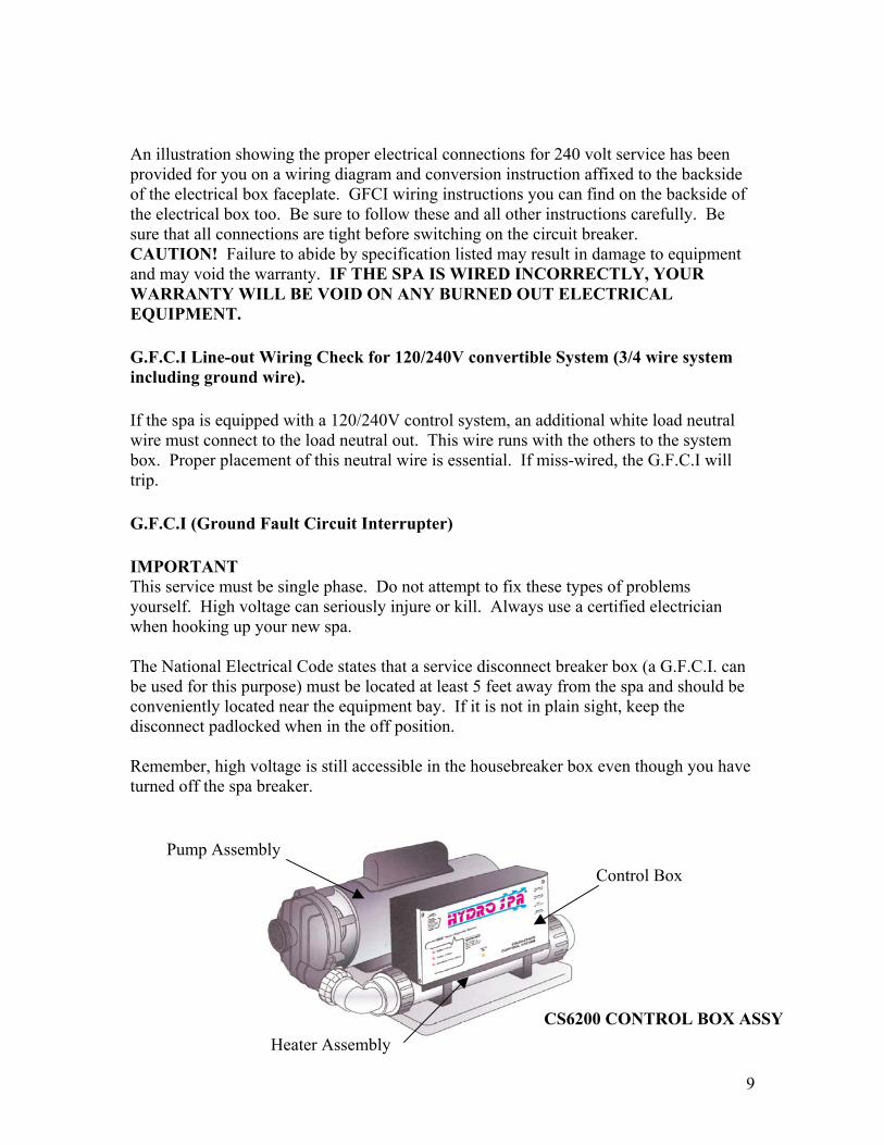
CS6200 CONTROL BOX ASSY
Control Box
Heater Assembly
Pump Assembly
9

CS6200 CONTROL BOX POWER SWITCH DIAGRAM
POWER SWITCH (OPTIONAL)
POWER DETECTION SWITCH (OPTIONAL)
The power test switch allows you to verify that voltage is being supplied to your system. Simply press the switch toward the rear of the enclosure to see the Line 1 voltage indicator illuminate then press the switch toward the front of the enclosure to see the Line 2 voltage indicator (240-Volt Models only) illuminate.
If equipped, your system may incorporate a power switch. This switch will turn power either on or off to the internal circuitry and connected components.
10
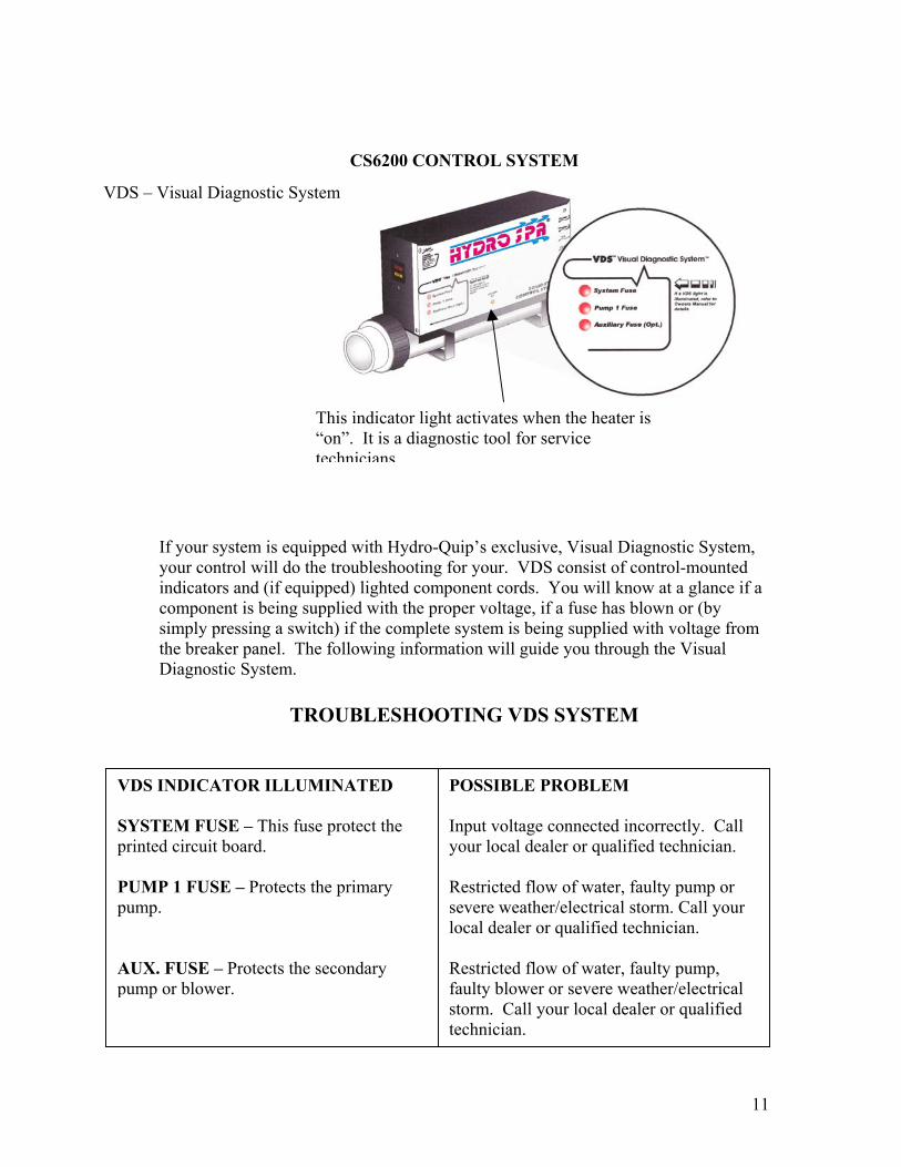
CS6200 CONTROL SYSTEM
VDS – Visual Diagnostic System
If your system is equiyour control will do tindicators and (if equcomponent is being ssimply pressing a swithe breaker panel. ThDiagnostic System.
TR
This indicator light activates when the heater is “on”. It is a diagnostic tool for service technicians.
pped with Hydro-Quip’s exclusive, Visual Diagnostic System, he troubleshooting for your. VDS consist of control-mounted ipped) lighted component cords. You will know at a glance if a upplied with the proper voltage, if a fuse has blown or (by tch) if the complete system is being supplied with voltage from e following information will guide you through the Visual
OUBLESHOOTING VDS SYSTEM
VDS INDICATOR ILLUMINATED SYSTEM FUSE – This fuse protect the printed circuit board. PUMP 1 FUSE – Protects the primary pump. AUX. FUSE – Protects the secondary pump or blower.
POSSIBLE PROBLEM Input voltage connected incorrectly. Call your local dealer or qualified technician. Restricted flow of water, faulty pump or severe weather/electrical storm. Call your local dealer or qualified technician. Restricted flow of water, faulty pump, faulty blower or severe weather/electrical storm. Call your local dealer or qualified technician.
11
OPERATION PROCEDURES
START UP PREPARATION
Before performing the operations in this section, make sure you have read and understand all of the previous instructions set forth in this manual. Make sure the spa has been installed correctly, including electrical wiring connections as specified in the wiring diagram.
c
Winterizing Your Spa Warning: Allowing the spa water to freeze will cause severe damage to the spa shell, equipment, and plumbing and your warranty will be void. Using your spa in freezing cold weather, it is critical that a water temperature is maintained well above freezing. Freeze Protection Your Hydro Spa is equipped with a special feature called freeze protection. If the high limit sensor detects 55 degrees F at the heater, then all the equipment is automatically activated to provide freeze protection. See details in electrical control system. Warning – We strongly recommend that you inspect and test your spa and controls on a daily basis during periods when temperatures are below 32 degrees F.
Every installation is different and many fa
Filling Your Spa Make sure GFCI breaker that
supplies your spa equipment power is shut off. Filling your spa is the first step in
maintaining water quality and chemical balance. Use only clear, uncontaminated potable water when filling your spa. Never use hot water. This will prevent scaling and corrosion from your hot water tank from entering the spa.
Water Level The correct water fill level may vary with each individual installation. Every person entering a spa displaces a given volume of water. Once in the tub, the water level should be just above the top neck jets. Chemically Treat Water Immediately To assure the maintenance of water quality it is imperative that you chemically threat the spa water immediately upon completion of filling.
12
DRAINING YOUR SPA
Turn Power Off . Remove Drain Valve Safety Cap – Attach a standard garden hose to drain valve. Select A Safe Suitable Drain – Route hose to a sewer drain capable of safely
assimilating 300 plus gallons of water, which may contain both unsanitary contaminants and chemical residue. Open drain valve.
WARRANTY – Do Not Supply Power To An Empty Spa! - This could damage your electrical equipment and pumps, voiding warranty. Remove any remaining water with a shop-vac, sponge and pail, or simply dilute in your fresh fill. Do not forget to close the drain connection before refilling. Cleaning the Spa Interior
To preserve the sheen of your tub’s surface, it is crucial that you void using abrasive cleaners or cleaners which have adverse chemical effect on the surface. See your authorized Hydro Spa Dealer
Pillow Care Remove and clean the headrest pillows as needed with soapy water using a cloth
or soft-bristle brush. To maintain water resistance and luster, apply a quality vinyl conditioner once a month. Always remove the pillows when adding chemical shock treatment to the tub
water. The pillows can be returned to the tub when the sanitizer reading drops below 5
ppm.
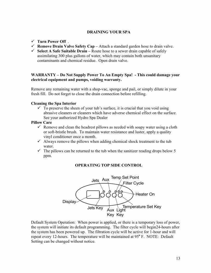
OPERATING TOP SIDE CONTROL
AuKe
Jets
xy
Temperature Set Key
Heater On
Filter CycleAux
Jets KeyDisplay
Temp Set Point
LightKey
Default System Operation: When power is applied, or there is a temporary loss of power, the system will initiate its default programming. The filter cycle will begin24-hours after the system has been powered up. The filtration cycle will be active for 1-hour and will repeat every 12-hours. The temperature will be maintained at 95o F. NOTE: Default Setting can be changed without notice.
13

Pump 1 Key (Jets 1): Press this key once to turn Pump 1 onto Low speed, press this key a second time to turn Pump 1 onto High speed, a third press will turn the pump off. A built-in timer will shut the pump off after 20 minutes of operation unless done so manually. The Pump 1 indicator will illuminate while the pump is running. If the filter cycle indicator is illuminated, a filtration cycle has begun and you will not be able to turn the pump off.
Aux Key (Aux): Press this key once to turn Aux on, press this key a second time to turn Aux off
Light Key: Press this key to turn the Light on and off. The light will automatically shut off after 2 hours.
Temperature Set Keys: Press the Temperature Set Key Up to increase the desired temperature. Release and press again to lower the temperature. The temperature can be adjusted in 1o F increments from 59o F to 104 o F (5o C to 40 o C). The new setting will remain on the display for 5 seconds as a confirmation. During this time the Temperature Program indicator will illuminate to let you know this is the desired and not the actual temperature. After 5 seconds the display will return to the current temperature reading. When the temperature drops to 1 degree F below the set temperature, the heater will be turned on until the temperature is 1 degree F above the set temperature. The heater On indicator will illuminate while the heater is on and flash when there is a call for heat and the heater has not yet been activated.
PROGRAMMING FILTRATION
Programming Filter Cycles: You may choose to filter the spa 1, 2 or 3 times per day as required to keep the water clean and sanitary. Press and hold the Pump Key. The current setting will be displayed. Press and hold the Temperature Set Key to increase or decrease the frequency of the filtration cycles per day. The filter cycle is now set. The cycles will repeat every 8, 12 or 24 hours within a 24-hour period starting from the time programmed. It is recommended to schedule the filtration cycles so they do not interfere with sleeping hours.
14
Programming Filter Cycle Duration: You may choose to filter your spa 60, 120, 180 or 480 minutes per cycle as required to keep the water clean and sanitary. Press and hold the Light Key. The current duration of the filter cycle will be displayed. Press and hold the Temperature Set Key in increase or decrease the duration of the filter cycle. The duration is now set. To start a filter cycle immediately, press and hold the Light Key. Note: If a Key is not pressed with 5 seconds during programming, the system will revert back to the monitoring mode. If the Pump and/or light were turned on during the programming process, turn them off. The system will revert back to display the water temperature within 5 seconds. Power Loss: Any interruption of power will cause the unit to reset and revert to the default programming of 95 F set point temperature and 2, 1-hour filtration cycles.
ADDITIONAL FEATURES Smart Winter Mode: If the system detects ambient conditions below a present factory setting, the system will automatically activate the Smart Winter Mode for a period of 24 hours. In this mode, if a pump has not been powered in the last 2 hours, the system will turn it on for a minute to prevent freezing. The filter Mode light indicator will flash while the pump is running in this mode. Note: If you notice the pump coming on every 2 hours. This is the most likely cause. This will continue for a 24-hour period. This is normal and is the systems protection against freezing. Over Temperature Protection: If the water temperature exceeds 112 F at the Temperature sensor 3 flashing dots will appear below the temperature display and the heater as well as all other outputs will shut off. After the water has cooled down power to the spa must be cycled on then off to reset the system. If the spa water temperature does not seem to elevated, the error indication may have been caused by poor water flow or electrical line interference (thunder storms, voltage surges, etc.). Simply reset and monitor the system. Power-Up Detection: Upon first powering the system or if a power outage occurs, the display will flash until a key is pressed. Air Volume Control – (AVC) The handle valve is used to select jet action between groups of jets, to customize the therapy action. Adjust to desired therapy action – handle moves only 180 degrees.
OZONE GENERATOR Ozone is injected into the spa water during the filtration cycle. The ozone generator (if equipped) operates in conjunction with low speed pump operation and ozone injector. The ozone is injected into the water to supplement chemical sanitizers, kill bacteria,
15
oxidize organics, and control minerals. Anytime the pump, the air blower, or the light is turned on, the ozone will turn off.
OZONE GENERATOR SAFETY INSTRUCTIONS – OPTIONAL
Do not add any device that could, or attempt in anyway to, interrupt the flow of
ozone to spa water. Do not allow ozone level to reach or exceed 0.1 PPM. Do not attempt to energize ozone generator with ozonator’s cover off. The internal lamp in the ozone generator is intended for application only where
humans will not be exposed to the ultraviolet radiation produced. Do not block ozone jets or could cause damage to ozonator and void warranty.
FILTER ASSEMBLIES AND PARTS
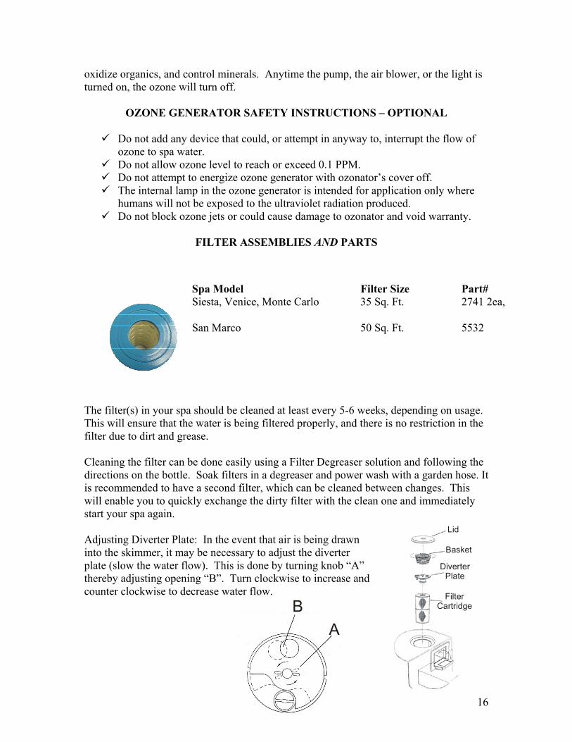
Spa Model Filter Size Part# Siesta, Venice, Monte Carlo 35 Sq. Ft. 2741 2ea, San Marco 50 Sq. Ft. 5532
The filter(s) in your spa should be cleaned at least every 5-6 weeks, depending on usage. This will ensure that the water is being filtered properly, and there is no restriction in the filter due to dirt and grease. Cleaning the filter can be done easily using a Filter Degreaser solution and following the directions on the bottle. Soak filters in a degreaser and power wash with a garden hose. It is recommended to have a second filter, which can be cleaned between changes. This will enable you to quickly exchange the dirty filter with the clean one and immediately start your spa again. Lid
Basket
Diverter Plate
FilterCartridge
Adjusting Diverter Plate: In the event that air is being drawn into the skimmer, it may be necessary to adjust the diverter plate (slow the water flow). This is done by turning knob “A” thereby adjusting opening “B”. Turn clockwise to increase and counter clockwise to decrease water flow.
16
AB
SPA SERIAL NUMBER
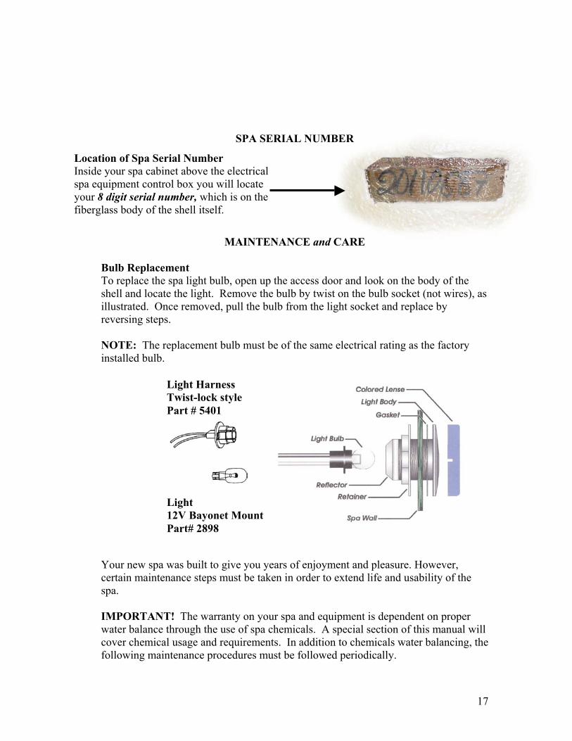
Location of Spa Serial Number
Inside your spa cabinet above the electrical spa equipment control box you will locate your 8 digit serial number, which is on the fiberglass body of the shell itself.
MAINTENANCE and CARE Bulb Replacement To replace the spa light bulb, open up the access door and look on the body of the shell and locate the light. Remove the bulb by twist on the bulb socket (not wires), as illustrated. Once removed, pull the bulb from the light socket and replace by reversing steps. NOTE: The replacement bulb must be of the same electrical rating as the factory installed bulb. Light Harness
Twist-lock style Part # 5401
Light
12V Bayonet Mount Part# 2898
Your new spa was built to give you years of enjoyment and pleasure. However, certain maintenance steps must be taken in order to extend life and usability of the spa. IMPORTANT! The warranty on your spa and equipment is dependent on proper water balance through the use of spa chemicals. A special section of this manual will cover chemical usage and requirements. In addition to chemicals water balancing, the following maintenance procedures must be followed periodically.
17

Cleaning The Spa The spa shell should be cleaned with a mild soap solution. Do not use solvents. The spa should always be clean and dry before being moved or stored. Maintaining The Spa Cover The spa cover should be cleaned monthly. To clean the spa cover, use water and a non-abrasive cleaner on the entire cover. Rinse the cover with a garden hose to remove any cleaner residue. Dry the cover entirely. You should also use a non-silicone based vinyl conditioner on the cover after you clean it. This will protect the cover from sun damage.
MAINTENANCE SCHEDULE Daily
Check the water level and refill the spa to the proper level Check the pH balance and sanitizer level. Adjust if necessary. Clean the surface of the water with a skimming net.
Weekly Clean the spa shell at the waterline. Check and thoroughly clean the filter if needed. Replace the filter if needed. (Always have a spare.)
Monthly Clean the spa cover. Soak the filter for two hours in a trisodium phosphate (TSP) solution. Rinse
the filter in clean water. Every Three Months
Drain the spa and refill with clean water. Sanitize and test the pH of the water. Check for any leaks around the pump or joints in the pipes. The seals will
wear out over time; detecting leaks early can reduce repair cost. Clean the interior of the spa. DO NOT use solvents or waxes.
Your Cabinet & Cedar Skirting Your cabinet has an access panel or door to the internal parts which consists of a pump or pumps, motor or motors, heater, ozonator (if you have one), filter housing, hoses, and wiring to provide electricity to your control system. The cabinet frame is made of weather treated wood, and covered outside by either redwood, cedar, cypress or TimberStone TM siding. The cabinet should be treated just like any other piece of furniture in your home. If spa will be setting outside in the weather, remember that it will be out in all types of
18
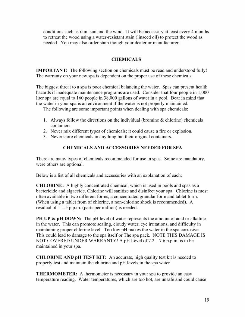
conditions such as rain, sun and the wind. It will be necessary at least every 4 months to retreat the wood using a water-resistant stain (linseed oil) to protect the wood as needed. You may also order stain though your dealer or manufacturer.
CHEMICALS
IMPORTANT! The following section on chemicals must be read and understood fully! The warranty on your new spa is dependent on the proper use of these chemicals.
The biggest threat to a spa is poor chemical balancing the water. Spas can present health hazards if inadequate maintenance programs are used. Consider that four people in 1,000 liter spa are equal to 160 people in 38,000 gallons of water in a pool. Bear in mind that the water in your spa is an environment if the water is not properly maintained.
The following are some important points when dealing with spa chemicals: 1. Always follow the directions on the individual (bromine & chlorine) chemicals
containers. 2. Never mix different types of chemicals; it could cause a fire or explosion. 3. Never store chemicals in anything but their original containers.
CHEMICALS AND ACCESSORIES NEEDED FOR SPA There are many types of chemicals recommended for use in spas. Some are mandatory, were others are optional. Below is a list of all chemicals and accessories with an explanation of each: CHLORINE: A highly concentrated chemical, which is used in pools and spas as a bactericide and algaecide. Chlorine will sanitize and disinfect your spa. Chlorine is most often available in two different forms, a concentrated granular form and tablet form. (When using a tablet from of chlorine, a non-chlorine shock is recommended). A residual of 1-1.5 p.p.m. (parts per million) is needed. PH UP & pH DOWN: The pH level of water represents the amount of acid or alkaline in the water. This can promote scaling, cloudy water, eye irritations, and difficulty in maintaining proper chlorine level. Too low pH makes the water in the spa corrosive. This could lead to damage to the spa itself or The spa pack. NOTE THIS DAMAGE IS NOT COVERED UNDER WARRANTY! A pH Level of 7.2 – 7.6 p.p.m. is to be maintained in your spa. CHLORINE AND pH TEST KIT: An accurate, high quality test kit is needed to properly test and maintain the chlorine and pH levels in the spa water. THERMOMETER: A thermometer is necessary in your spa to provide an easy temperature reading. Water temperatures, which are too hot, are unsafe and could cause
19

damage to your spa's finish. Recommended temperatures ranges are 102 o F to 104 o F. water in excess of 104 o F is UNSAFE! The following chemicals are not necessary for safe use in your spa. However, depending on the type of water available to you, the products are highly recommended. In most cases, these products will increase the life of your spa and equipment and will make the spa more pleasant to maintain. SPA SHOCK: This chemical oxidizes or “burns-out” most organic contaminants in the spa water. It works together with the chlorine in your spa. Most often it is a weekly or bi-weekly treatment. (This product is mandatory when using a tablet form of chlorine, bromine or granular). STAIN & SCALE REMOVER: A stain and scale remover prevents water discoloration due to certain minerals in the water. It also prevents scaling which could corrode the pump and shorten its lifespan. Depending on the brand, stain & scale remover is most often a weekly treatment. WATER CLARIFIER: This product is designed to coagulate small particle of unwanted dirt or grime in order to aid filtration. As with the stain & scale remover is most often a weekly treatment. Use of this chemical will prolong your filtration system and filter a spa. ALKALINITY INCREASER: Total alkalinity in the water is the combined measurement of a group of alkaline sales in the water. Too low alkalinity may cause the pH levels to fluctuate excessively when being adjusted. The ideal range for total alkalinity is between 90 -150 p.p.m. range. (A special test kit is required). CALCIUM HARNESS INCREASER: Calcium is the mineral in water, which determines whether the water is “soft” or “hard”. Low calcium can make the spa water is ideal in the 225 - 275 p.p.m. range. (A special test kit is required). Test Strips are recommended for testing. BROMINE: Bromine is an alternative to chlorine as a disinfectant. The benefit of using bromine is that it has less-odor and is more pH independent.
CHEMICAL STARTUP
The initial chemical startup of your new spa involves a number of simple steps. Most important is adjusting the pH level of the water and introduction chlorine (or bromine) into the spa. Follow the step-by-step procedures listed below and remember to follow the directions on each individual chemical bottle.
Test both pH and the chlorine/bromine levels of the water. Adjust the pH level by adding degreaser or pH increaser. NOTE! The pH may be too high or too low to fully adjust in one treatment. Do not try to make large changes in the pH with one treatment; you must
20

increase or reduce the pH gradually to ensure damage does occur to your spa or equipment. Add chlorine/bromine into the water in the method your have chosen. NOTE! If a tablet of chlorine/bromine is used, “shock” the water first with the spa shock. Add the Water Clarifier and Stain & Scale chemicals as recommended on the chemical bottle.
CHEMICAL TROUBLE SHOOTING GUIDE
Just as with anything else, adjusting and balancing spa chemicals takes practice. Below are a number of common problems, which may arise in your spa water. Try curing the problem by following the trouble-shooting guide. If the problem persists, or the problem is not covered in the following guide contact your authorized After Hours Dealer. PROBLEM SOLUTION Cloudy Water
1. Cloudy water is normally due to high pH or low chlorine/bromine levels. Test the water and correct the pH levels and chlorine/bromine levels.
2. Excessive use of defoamer chemical may cause the water to turn cloudy.
Foamy Water Use defoamer in the water. This chemical must be used only when necessary. It will cause the water to turn cloudy if used excessively.
Green or Yellow Water This usually means the water is low on chlorine/bromine levels. “Shock” the water and test for chlorine/bromine levels. Add water clarifier.
Scum Line A scum line will normally appear on the water level of the spa. However, it us unusual for scum line to persist. Ad stain and remover as directed.
TOP SIDE ERROR IDENTIFICATION
104
Three Flashing Dots with Pump Off Pressure or Flow Switch Activated: If 3 flashing dots appear below the temperature display while there is no pump operating, turn the pump on. If the 3 flashing dots went away this indicates that the pressure or flow switch was activated although there was no water flow. (Contact Your Local Dealer for Service)
21
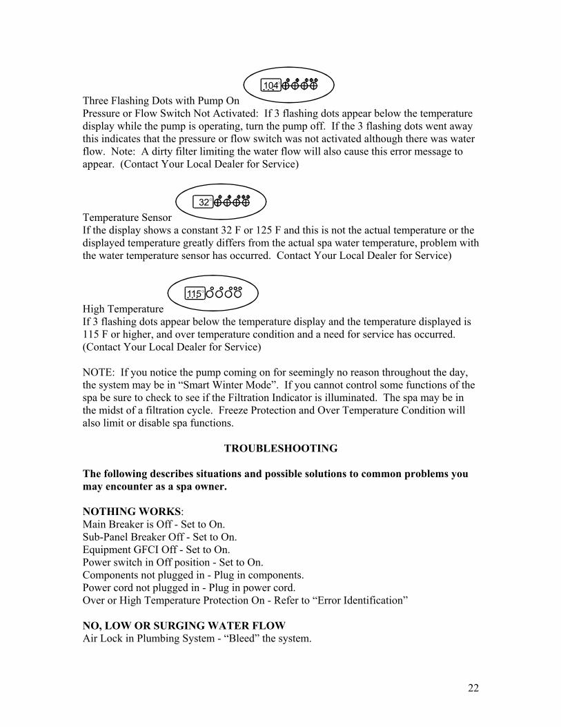
Three Flashing Dots with Pump On 104
Pressure or Flow Switch Not Activated: If 3 flashing dots appear below the temperature display while the pump is operating, turn the pump off. If the 3 flashing dots went away this indicates that the pressure or flow switch was not activated although there was water flow. Note: A dirty filter limiting the water flow will also cause this error message to appear. (Contact Your Local Dealer for Service)
Temperature Sensor 32
If the display shows a constant 32 F or 125 F and this is not the actual temperature or the displayed temperature greatly differs from the actual spa water temperature, problem with the water temperature sensor has occurred. Contact Your Local Dealer for Service)
High Temperature 115
If 3 flashing dots appear below the temperature display and the temperature displayed is 115 F or higher, and over temperature condition and a need for service has occurred. (Contact Your Local Dealer for Service) NOTE: If you notice the pump coming on for seemingly no reason throughout the day, the system may be in “Smart Winter Mode”. If you cannot control some functions of the spa be sure to check to see if the Filtration Indicator is illuminated. The spa may be in the midst of a filtration cycle. Freeze Protection and Over Temperature Condition will also limit or disable spa functions.
TROUBLESHOOTING
The following describes situations and possible solutions to common problems you may encounter as a spa owner. NOTHING WORKS: Main Breaker is Off - Set to On. Sub-Panel Breaker Off - Set to On. Equipment GFCI Off - Set to On. Power switch in Off position - Set to On. Components not plugged in - Plug in components. Power cord not plugged in - Plug in power cord. Over or High Temperature Protection On - Refer to “Error Identification” NO, LOW OR SURGING WATER FLOW Air Lock in Plumbing System - “Bleed” the system.
22

Restricted Flow - Insure that the water shut-off valves are open and that suction fittings are not blocked by debris. Dirty Filter - Clean or replace filter. Low Water Level - Increase water level to recommended level. NO LOW SPEED PUMP OPERATION Low level Programming Incorrect - Contact your local dealer. Over or High Temperature Protection - Turn power off then back on to reset. Pump Not Plugged-In - Plug in the Pump. NO PUMP OR BLOWER OPERATION Pump or Blower Not Plugged-In - Plug in the Blower or Pump Over or High Temperature Protection On - Turn power off then back on to reset. NO THERAPY JET OPERATION Water Shut-Off Valves are Closed - Open Shut-Off Valves. Dirty Filter - Clean or Replace Filter Jets Not Properly Adjusted - Adjust Jets properly. Diverter Valve not Properly Adjusted - Adjust diverter valve properly. Thermal Overload Tripping - Check for restricted flow of water. Over or High Temperature Protection On - Turn power off then back on to reset. WATER LEAKS Spa Overfilled - Adjust water level. Too Many People in the spa - Adjust water level. Drain - Valve left Open - Close drain valve. Coupling or Unions Loose - Tighten or contact your local dealer. Pump Seal Leaking - Contact your local dealer. Plump Seal leaking - Contact your local dealer. Plumbing / Connection Leaking - Contact your local dealer. Water Leaking from Spaside Control - Contact your local dealer. Water in Air Blower Plumbing - Contact your local dealer. NO HEAT Temperature Not Set Correctly - Adjust Set Point. Over or High Temperature Protection On - Turn power off then back on to reset. Current Limiting On - 120V Systems will not heat if High Speed or Blower is on. Contact your local dealer. No Power - Reset breaker at service panel. Low Water Flow - Clean or Replace Filter. HIGH HEAT Temperature Sensor Not in Dry-Well - Place sensor in dry-well. Temperature Set Too High - Adjust Set Point. High Ambient Temperature - Remove spa cover.
23

GFCI TRIPS OCCASIONALLY Lightning or Electrical Storm, Power Surge, Extremely Humid Conditions, or Radio Frequency Interference - Reset GFCI. NOTE: GFCI must be properly grounded and bonded. GFCI TRIPS IMMEDIATELY Defective Component - Contact a qualified service technician or the factor for assistance. NO LIGHT OPERATION Light Bulb Defective - Replace bulb or contact your local dealer. Reflector has Fallen Off - Replace deflector or contact your local dealer. Light Not Plugged-In - Plug in the light.
24
25

26


![A BESPOKE APPROACH TO BUSINESS - Leisure Opportunities · A BESPOKE APPROACH TO BUSINESS ESPA [pron e’spa] noun. A ‘World’ of Spa and Wellness. Value: verb. The Ultimate Spa](https://img.pdfslide.us/doc/110x75/5ed7f5e0c64afa2ac75875c2/a-bespoke-approach-to-business-leisure-opportunities-a-bespoke-approach-to-business.jpg)