Embed Size (px)
Citation preview
GRUNDFOS DATA BOOKLET
Hydro Multi-EGrundfos Hydro Multi-E booster systems with 2 to 4 CRE, CRIE or CME pumps
Ta
ble
of c
on
ten
ts
2
Hydro Multi-E
1. Introduction 3Benefits 4
2. Product data 5Performance range 5Type key 7Operating conditions 8
3. Construction 9System components 9Materials 9Diaphragm tank 10Environmental considerations 10
4. Installation 11Mechanical installation 11Electrical installation 11
5. Control of Hydro Multi-E 12Control options 12Control modes 14
6. Functions 15Overview of functions 15Description of functions 16Overview of inputs/outputs 17
7. Sizing 18Flow 18Head 19Inlet pressure 19Understanding the curve charts 20
8. Performance curves and technical data 22Curve conditions 22
9. Optional equipment 42
10. Accessories 44Grundfos GO Remote 44CIU communication interface units 45Extra documentation 45
11. Further product information 46WebCAPS 46WinCAPS 47GO CAPS 48
Intr
od
uc
tio
n
Hydro Multi-E 1
1. Introduction
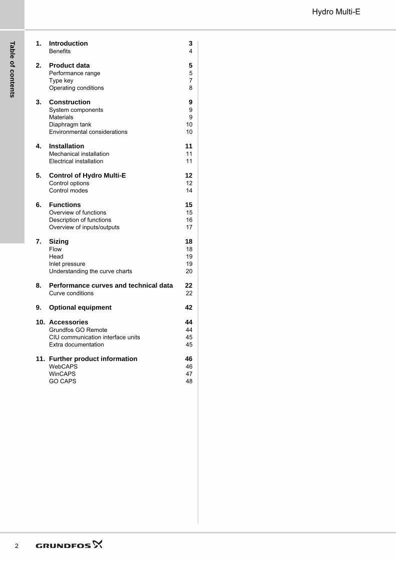
Grundfos Hydro Multi-E booster systems are designed for the transfer and pressure boosting of clean water in places such as
• blocks of flats
• hotels
• industry
• hospitals
• schools.
Grundfos Hydro Multi-E booster systems consist of two to four Grundfos CRE, CRIE pumps or two or three CME-A, CME-I pumps connected in parallel and mounted on a common base frame provided with all necessary fittings.
As standard, the Hydro Multi-E is supplied with the following:
• base frame
• pumps
• suction and discharge manifolds
• pressure switch as dry-running protection
• one or two discharge-pressure sensors, depending on pump size
• non-return valves, one per pump
• isolating valves, two per pump
• pressure gauge
• diaphragm tank
• breaker box.
On delivery, the Grundfos Hydro Multi-E booster system is factory-tested and ready for operation.
Fig. 1 Hydro Multi-E with three single-phase pumps
The Hydro Multi-E is available in two versions, depending on pump size.
Hydro Multi-E, 0.37 to 2.2 kW
The pumps incorporated in this Hydro Multi-E system are fitted with the new-generation MGE motors which are permanent-magnet motors with a high-efficiency frequency converter. The motors ensure an even higher efficiency than the previous version of the booster system. The MGE motors have a total efficiency which exceeds the IE4 Super Premium Efficiency level defined for fixed-speed motors.
The Hydro Multi-E with pumps in this range offers additional functions:
• multi-master function
• pipe-filling function
• predefined setpoint
• external setpoint influence
• limit-exceeded function.
Hydro Multi-E, 3.0 to 7.5 kW
The Hydro Multi-E with pumps in this range is fitted with MGE motors which are asynchronous motors with built-in frequency converter. These motors are IE3-compliant as standard.
TM
05
82
41
22
13Pump Non-return
valve
Discharge-pressure sensor
Pressure gauge
Isolating valve
Diaphragm tankBreaker box
Pressure switch
3
Intro
du
ctio
n
4
Hydro Multi-E1
Benefits
Plug-and-pump solution
The Hydro Multi-E is supplied as a complete preassembled system mounted on a base frame. The only task left is to connect the pipes and the power supply.
User-friendliness
The Hydro Multi-E is a highly intelligent booster system which is capable of controlling two to four speed-controlled pumps in cascade. The Hydro Multi-E is one of our most simple booster systems to start up and operate. It has only two buttons for complete control of the system. Alternatively, you can use Grundfos GO Remote for setup and control.
Perfect constant-pressure control
The speed-controlled pumps are perfectly controlled and adjusted by the PI controller of the Hydro Multi-E to deliver the correct pressure at the required flow.
Reliability
The Grundfos CRE, CRIE and CME pumps are known for their reliability and long life. The PI controller is protected inside the pump and this has proven to be a very reliable solution.
Multi-master function (0.37 to 2.2 kW)
All pumps that have a discharge-pressure sensor connected are capable of taking control of the entire booster system. This means that the system will continue to operate as a booster system even if one or more of the pumps or sensors are unavailable. Compared to systems with only one sensor, this makes the Hydro Multi-E an extremely reliable solution.
Redundant sensor (0.37 to 2.2 kW)
No system is more reliable than the weakest component. In connection with booster systems, it is common to rely on only one pressure measurement. However, that makes the operation extremely dependent on one single sensor. On the Hydro Multi-E, we do not depend on one sensor (single point of failure) as the booster system is supplied with two discharge-pressure sensors as standard.
Tested and ready to use
Before delivery, all Hydro Multi-E systems are carefully tested to Grundfos standard, i.e. pressure-tested and tested for full functionality.
Low energy consumption
The Hydro Multi-E ensures low energy consumption through speed-controlled pumps, automatic cascade control of the pumps and highly efficient low-flow operation. The highly efficient motors and pumps also contribute to the overall high efficiency of the Hydro Multi-E system.
Pro
du
ct
da
ta
Hydro Multi-E 2
2. Product data
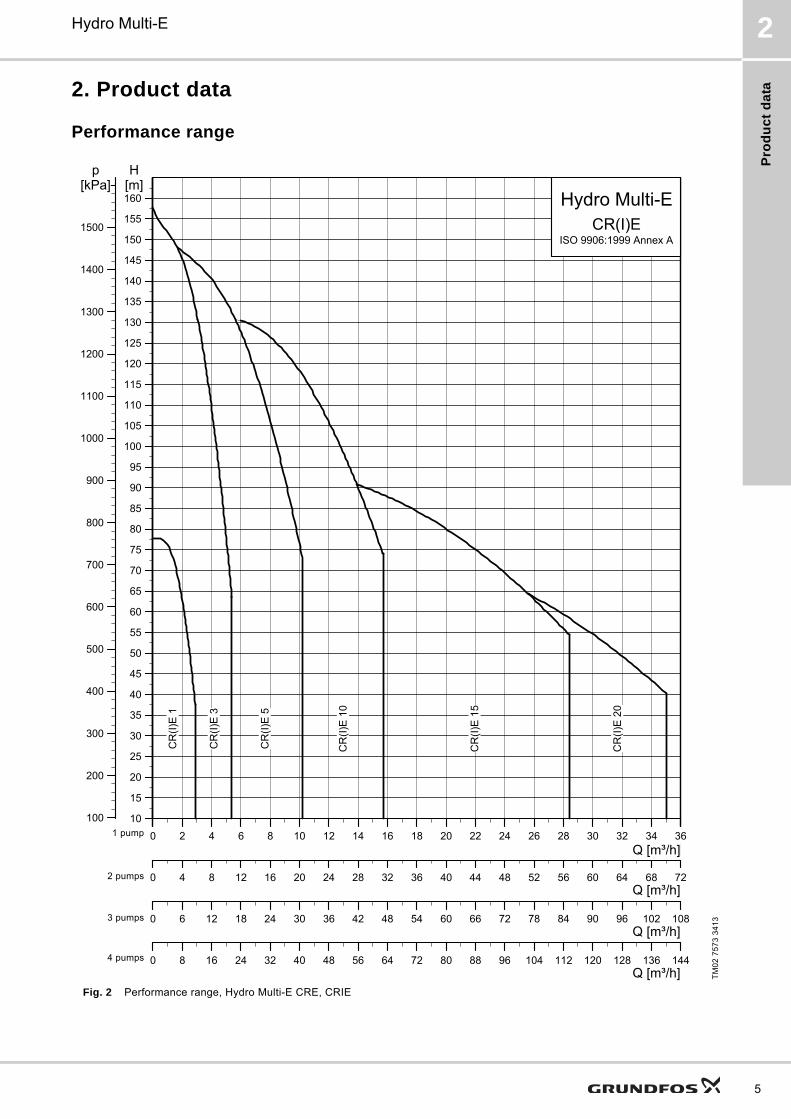
Performance range
Fig. 2 Performance range, Hydro Multi-E CRE, CRIE
TM
02
75
73
34
13
0 2 4 6 8 10 12 14 16 18 20 22 24 26 28 30 32 34 36Q [m³/h]
10
15
20
25
30
35
40
45
50
55
60
65
70
75
80
85
90
95
100
105
110
115
120
125
130
135
140
145
150
155
160
H[m]
100
200
300
400
500
600
700
800
900
1000
1100
1200
1300
1400
1500
[kPa]p
Hydro Multi-ECR(I)E
ISO 9906:1999 Annex A
CR
(I)E
20
CR
(I)E
15
CR
(I)E
10
CR
(I)E
5
CR
(I)E
3
CR
(I)E
1
0
10
15
20
25
30
35
40
45
50
55
60
65
70
75
80
85
90
95
100
105
110
115
120
125
130
135
140
145
150
155
160
0 4 8 12 16 20 24 28 32 36 40 44 48 52 56 60 64 68 72Q [m³/h]
0
10
15
20
25
30
35
40
45
50
55
60
65
70
75
80
85
90
95
100
105
110
115
120
125
130
135
140
145
150
155
160
0 6 12 18 24 30 36 42 48 54 60 66 72 78 84 90 96 102 108Q [m³/h]
1 pump
2 pumps
3 pumps
0
Q [m³/h]
10
15
20
25
30
35
40
45
50
55
60
65
70
75
80
85
90
95
100
105
110
115
120
125
130
135
140
145
150
155
160
0 8 16 24 32 40 48 56 64 72 80 88 96 104 112 120 128 136 144Q [m³/h]
4 pumps
1 pump
2 pumps
3 pumps
4 pumps
5
Pro
du
ct d
ata
6
Hydro Multi-E2
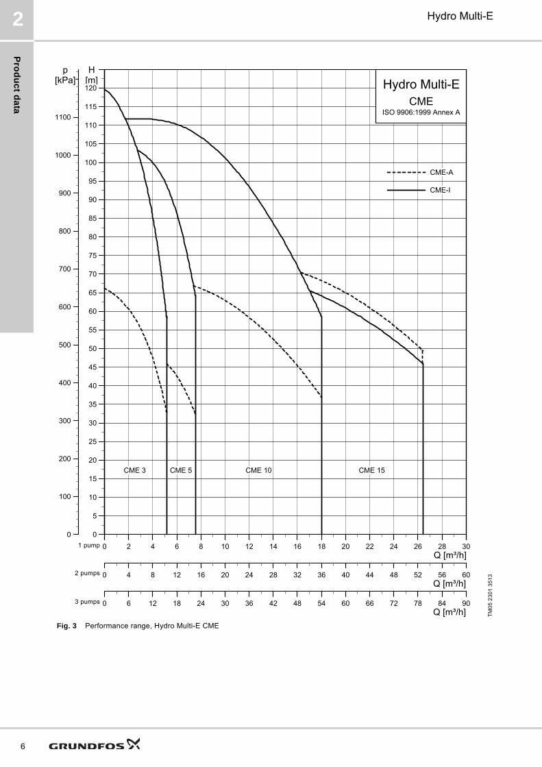
Fig. 3 Performance range, Hydro Multi-E CME
TM
05
23
01
35
13
0 2 4 6 8 10 12 14 16 18 20 22 24 26 28 30Q [m³/h]
0
5
10
15
20
25
30
35
40
45
50
55
60
65
70
75
80
85
90
95
100
105
110
115
H[m]
0
100
200
300
400
500
600
700
800
900
1000
1100
[kPa]p
Hydro Multi-ECME
ISO 9906:1999 Annex A
CME 3 CME 10 CME 15CME 5
CME-A
CME-I
0
0
5
10
15
20
25
30
35
40
45
50
55
60
65
70
75
80
85
90
95
100
105
110
115
120
0 4 8 12 16 20 24 28 32 36 40 44 48 52 56 60Q [m³/h]
0
0
5
10
15
20
25
30
35
40
45
50
55
60
65
70
75
80
85
90
95
100
105
110
115
120
0 6 12 18 24 30 36 42 48 54 60 66 72 78 84 90Q [m³/h]
1 pump
2 pumps
3 pumps
1 pump
2 pumps
3 pumps
Pro
du
ct
da
ta
Hydro Multi-E 2
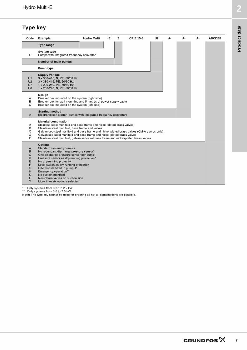
Type key
* Only systems from 0.37 to 2.2 kW.** Only systems from 3.0 to 7.5 kW.Note: The type key cannot be used for ordering as not all combinations are possible.
Code Example Hydro Multi -E 2 CRIE 15-3 U7 A- A- A- ABCDEF
Type range
ESystem typePumps with integrated frequency converter
Number of main pumps
Pump type
U1U2U7U8
Supply voltage3 x 380-415, N, PE, 50/60 Hz3 x 380-415, PE, 50/60 Hz1 x 200-240, PE, 50/60 Hz1 x 200-240, N, PE, 50/60 Hz
ABC
DesignBreaker box mounted on the system (right side) Breaker box for wall mounting and 5 metres of power supply cableBreaker box mounted on the system (left side)
AStarting methodElectronic soft starter (pumps with integrated frequency converter)
ABCGP
Material combinationStainless-steel manifold and base frame and nickel-plated brass valves Stainless-steel manifold, base frame and valvesGalvanised-steel manifold and base frame and nickel-plated brass valves (CM-A pumps only)Galvanised-steel manifold and base frame and nickel-plated brass valvesStainless-steel manifold, galvanised-steel base frame and nickel-plated brass valves
ABCDEFGHKLX
OptionsStandard system hydraulicsNo redundant discharge-pressure sensor*One discharge-pressure sensor per pump*Pressure sensor as dry-running protection*No dry-running protectionLevel switch as dry-running protectionCIM module fitted in pump 1*Emergency operation**No suction manifoldNon-return valves on suction sideMore than six options selected
7
Pro
du
ct d
ata
8
Hydro Multi-E2
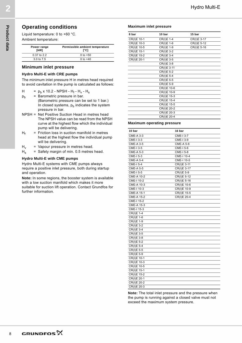
Operating conditionsLiquid temperature: 0 to +60 °C.
Ambient temperature:
Minimum inlet pressure
Hydro Multi-E with CRE pumps
The minimum inlet pressure H in metres head required to avoid cavitation in the pump is calculated as follows:
Hydro Multi-E with CME pumps
Hydro Multi-E systems with CME pumps always require a positive inlet pressure, both during startup and operation.
Note: In some regions, the booster system is available with a low suction manifold which makes it more suitable for suction lift operation. Contact Grundfos for further information.
Maximum inlet pressure
Maximum operating pressure
Note: The total inlet pressure and the pressure when the pump is running against a closed valve must not exceed the maximum system pressure.
Power range [kW]
Permissible ambient temperature [°C]
0.37 to 2.2 0 to +50
3.0 to 7.5 0 to +40
H = pb x 10.2 - NPSH - Hf - Hv - Hspb = Barometric pressure in bar.
(Barometric pressure can be set to 1 bar.) In closed systems, pb indicates the system pressure in bar.
NPSH = Net Positive Suction Head in metres headThe NPSH value can be read from the NPSH curve at the highest flow which the individual pump will be delivering.
Hf = Friction loss in suction manifold in metres head at the highest flow the individual pump will be delivering.
Hv = Vapour pressure in metres head.Hs = Safety margin of min. 0.5 metres head.
8 bar 10 bar 15 bar
CR(I)E 10-1 CR(I)E 1-4 CR(I)E 3-17
CR(I)E 10-3 CR(I)E 1-6 CR(I)E 5-12
CR(I)E 10-5 CR(I)E 1-9 CR(I)E 5-16
CR(I)E 15-1 CR(I)E 3-2
CR(I)E 15-2 CR(I)E 3-4
CR(I)E 20-1 CR(I)E 3-5
CR(I)E 3-8
CR(I)E 3-11
CR(I)E 5-2
CR(I)E 5-4
CR(I)E 5-5
CR(I)E 5-9
CR(I)E 10-6
CR(I)E 10-9
CR(I)E 15-3
CR(I)E 15-4
CR(I)E 15-5
CR(I)E 20-2
CR(I)E 20-3
CR(I)E 20-4
10 bar 16 bar
CME-A 3-3 CME-I 3-7
CME-I 3-3 CME-I 3-9
CME-A 3-5 CME-A 5-6
CME-I 3-5 CME-I 5-6
CME-A 5-3 CME-I 5-8
CME-I 5-3 CME-I 10-4
CME-A 5-4 CME-I 10-5
CME-I 5-4 CR(I)E 3-11
CME-A 5-5 CR(I)E 3-17
CME-I 5-5 CR(I)E 5-9
CME-A 10-2 CR(I)E 5-12
CME-I 10-2 CR(I)E 5-16
CME-A 10-3 CR(I)E 10-6
CME-I 10-3 CR(I)E 10-9
CME-A 15-1 CR(I)E 15-5
CME-A 15-2 CR(I)E 20-4
CME-I 15-2
CME-A 15-3
CME-I 15-3
CR(I)E 1-4
CR(I)E 1-6
CR(I)E 1-9
CR(I)E 3-2
CR(I)E 3-4
CR(I)E 3-5
CR(I)E 3-8
CR(I)E 5-2
CR(I)E 5-4
CR(I)E 5-5
CR(I)E 5-9
CR(I)E 10-1
CR(I)E 10-3
CR(I)E 10-5
CR(I)E 15-1
CR(I)E 15-2
CR(I)E 20-1
CR(I)E 20-2
CR(I)E 20-3
Co
ns
tru
cti
on
Hydro Multi-E 3
3. Construction
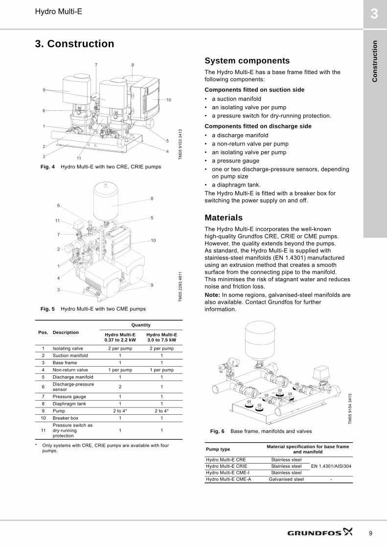
Fig. 4 Hydro Multi-E with two CRE, CRIE pumps
Fig. 5 Hydro Multi-E with two CME pumps
* Only systems with CRE, CRIE pumps are available with four pumps.
System componentsThe Hydro Multi-E has a base frame fitted with the following components:
Components fitted on suction side
• a suction manifold
• an isolating valve per pump
• a pressure switch for dry-running protection.
Components fitted on discharge side
• a discharge manifold
• a non-return valve per pump
• an isolating valve per pump
• a pressure gauge
• one or two discharge-pressure sensors, depending on pump size
• a diaphragm tank.
The Hydro Multi-E is fitted with a breaker box for switching the power supply on and off.
MaterialsThe Hydro Multi-E incorporates the well-known high-quality Grundfos CRE, CRIE or CME pumps. However, the quality extends beyond the pumps. As standard, the Hydro Multi-E is supplied with stainless-steel manifolds (EN 1.4301) manufactured using an extrusion method that creates a smooth surface from the connecting pipe to the manifold. This minimises the risk of stagnant water and reduces noise and friction loss.
Note: In some regions, galvanised-steel manifolds are also available. Contact Grundfos for further information.
Fig. 6 Base frame, manifolds and valves
TM
05
91
53
34
13
TM
05
22
93
48
11
Pos. Description
Quantity
Hydro Multi-E0.37 to 2.2 kW
Hydro Multi-E3.0 to 7.5 kW
1 Isolating valve 2 per pump 2 per pump
2 Suction manifold 1 1
3 Base frame 1 1
4 Non-return valve 1 per pump 1 per pump
5 Discharge manifold 1 1
6Discharge-pressure sensor
2 1
7 Pressure gauge 1 1
8 Diaphragm tank 1 1
9 Pump 2 to 4* 2 to 4*
10 Breaker box 1 1
11Pressure switch as dry-running protection
1 1
10
1
2
34
5
6
9
7 8
11
10
11 5
8
1
2
3
4
7
6
9
TM
05
91
54
34
13
Pump typeMaterial specification for base frame
and manifold
Hydro Multi-E CRE Stainless steel
EN 1.4301/AISI304Hydro Multi-E CRIE Stainless steel
Hydro Multi-E CME-I Stainless steel
Hydro Multi-E CME-A Galvanised steel -
9
Co
ns
truc
tion
10
Hydro Multi-E3
Diaphragm tankTo ensure optimum operation, the tank must be precharged with pressure.
The precharge pressure = 0.7 x setpoint.
The diaphragm tank precharge pressure must be measured in a pressureless system.
We recommend to refill the tank with nitrogen.
Environmental considerationsWe manufacture our motors and other products with a high degree of consideration for the environment in respect of materials, production methods, energy-saving operation and recycling of as many materials as possible.
The Grundfos A/S manufacturing company
• is certified as environmentally friendly in accordance with ISO 14001.
• is approved in accordance with European certification standard EMAS.
• holds an ISO 9001 certificate.
CE marking
Hydro Multi-E booster systems on the European market are CE-marked.
Fig. 7 CE-marking
TM
02
16
95
19
01
Ins
tall
ati
on
Hydro Multi-E 4
4. Installation
Mechanical installationA Hydro Multi-E booster system must be installed in a well-ventilated room to ensure sufficient cooling of the pumps. Hydro Multi-E is not suitable for outdoor installation.
Place the booster system in such a way that there is sufficient clearance around it for the operator to be able to work freely.
Enclosure class: IP54.
Insulation class: F.
Motor coolingTo ensure adequate cooling of motor and electronics, the following must be observed:
• Place the Hydro Multi-E in a well-ventilated room.
• The temperature of the cooling air must not exceed 40 °C.
• Motor cooling fins, holes in fan cover and fan blades must be kept clean.
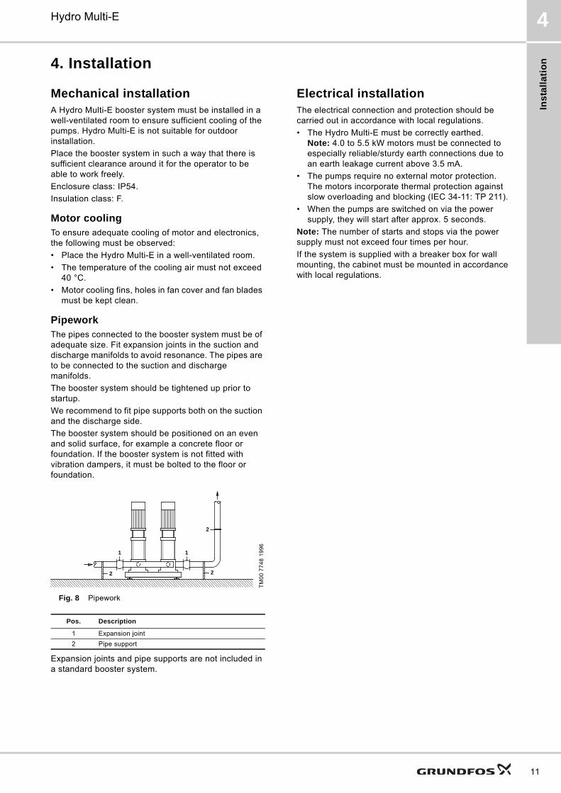
PipeworkThe pipes connected to the booster system must be of adequate size. Fit expansion joints in the suction and discharge manifolds to avoid resonance. The pipes are to be connected to the suction and discharge manifolds.
The booster system should be tightened up prior to startup.
We recommend to fit pipe supports both on the suction and the discharge side.
The booster system should be positioned on an even and solid surface, for example a concrete floor or foundation. If the booster system is not fitted with vibration dampers, it must be bolted to the floor or foundation.
Fig. 8 Pipework
Expansion joints and pipe supports are not included in a standard booster system.
Electrical installationThe electrical connection and protection should be carried out in accordance with local regulations.
• The Hydro Multi-E must be correctly earthed.Note: 4.0 to 5.5 kW motors must be connected to especially reliable/sturdy earth connections due to an earth leakage current above 3.5 mA.
• The pumps require no external motor protection.The motors incorporate thermal protection against slow overloading and blocking (IEC 34-11: TP 211).
• When the pumps are switched on via the power supply, they will start after approx. 5 seconds.
Note: The number of starts and stops via the power supply must not exceed four times per hour.
If the system is supplied with a breaker box for wall mounting, the cabinet must be mounted in accordance with local regulations.
TM
00
77
48
19
96
Pos. Description
1 Expansion joint
2 Pipe support
2
2
11
2
11
Co
ntro
l of H
yd
ro M
ulti-E
12
Hydro Multi-E5
5. Control of Hydro Multi-E
Control optionsCommunication with Hydro Multi-E is possible by means of the following:
• the control panel on the pumps
• Grundfos GO Remote
• a building management system.
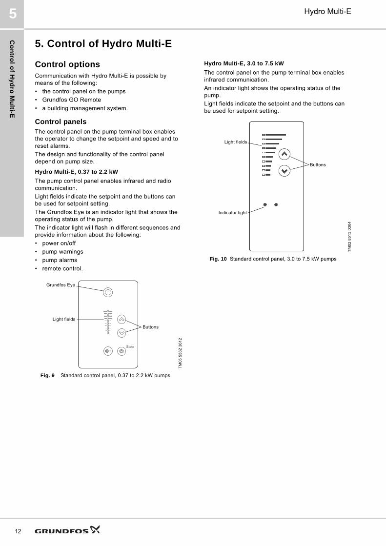
Control panelsThe control panel on the pump terminal box enables the operator to change the setpoint and speed and to reset alarms.
The design and functionality of the control panel depend on pump size.
Hydro Multi-E, 0.37 to 2.2 kW
The pump control panel enables infrared and radio communication.
Light fields indicate the setpoint and the buttons can be used for setpoint setting.
The Grundfos Eye is an indicator light that shows the operating status of the pump.
The indicator light will flash in different sequences and provide information about the following:
• power on/off
• pump warnings
• pump alarms
• remote control.
Fig. 9 Standard control panel, 0.37 to 2.2 kW pumps
Hydro Multi-E, 3.0 to 7.5 kW
The control panel on the pump terminal box enables infrared communication.
An indicator light shows the operating status of the pump.
Light fields indicate the setpoint and the buttons can be used for setpoint setting.
Fig. 10 Standard control panel, 3.0 to 7.5 kW pumps
TM
05
53
62
36
12
Stop
Grundfos Eye
Light fields
Buttons
TM
02
85
13
03
04
Light fields
Indicator light
Buttons
Co
ntr
ol
of
Hy
dro
Mu
lti-
E
Hydro Multi-E 5
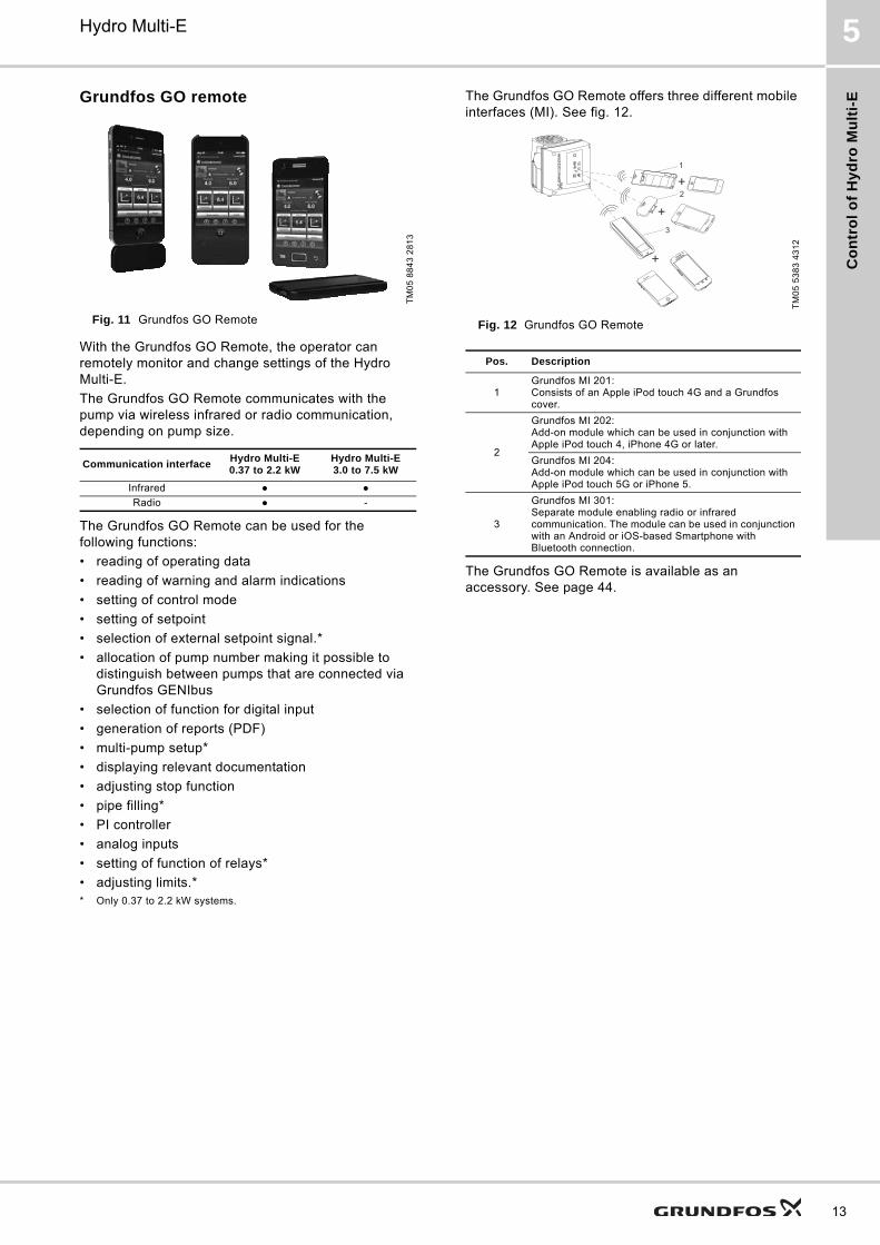
Grundfos GO remote
Fig. 11 Grundfos GO Remote
With the Grundfos GO Remote, the operator can remotely monitor and change settings of the Hydro Multi-E.
The Grundfos GO Remote communicates with the pump via wireless infrared or radio communication, depending on pump size.
The Grundfos GO Remote can be used for the following functions:
• reading of operating data
• reading of warning and alarm indications
• setting of control mode
• setting of setpoint
• selection of external setpoint signal.*
• allocation of pump number making it possible to distinguish between pumps that are connected via Grundfos GENIbus
• selection of function for digital input
• generation of reports (PDF)
• multi-pump setup*
• displaying relevant documentation
• adjusting stop function
• pipe filling*
• PI controller
• analog inputs
• setting of function of relays*
• adjusting limits.** Only 0.37 to 2.2 kW systems.
The Grundfos GO Remote offers three different mobile interfaces (MI). See fig. 12.
Fig. 12 Grundfos GO Remote
The Grundfos GO Remote is available as an accessory. See page 44.
TM
05
88
43
28
13
Communication interfaceHydro Multi-E0.37 to 2.2 kW
Hydro Multi-E3.0 to 7.5 kW
Infrared ● ●
Radio ● -
TM
05
53
83
43
12
Pos. Description
1Grundfos MI 201:Consists of an Apple iPod touch 4G and a Grundfos cover.
2
Grundfos MI 202:Add-on module which can be used in conjunction with Apple iPod touch 4, iPhone 4G or later.
Grundfos MI 204:Add-on module which can be used in conjunction with Apple iPod touch 5G or iPhone 5.
3
Grundfos MI 301:Separate module enabling radio or infrared communication. The module can be used in conjunction with an Android or iOS-based Smartphone with Bluetooth connection.
+
1
2
3
+
+
13
Co
ntro
l of H
yd
ro M
ulti-E
14
Hydro Multi-E5
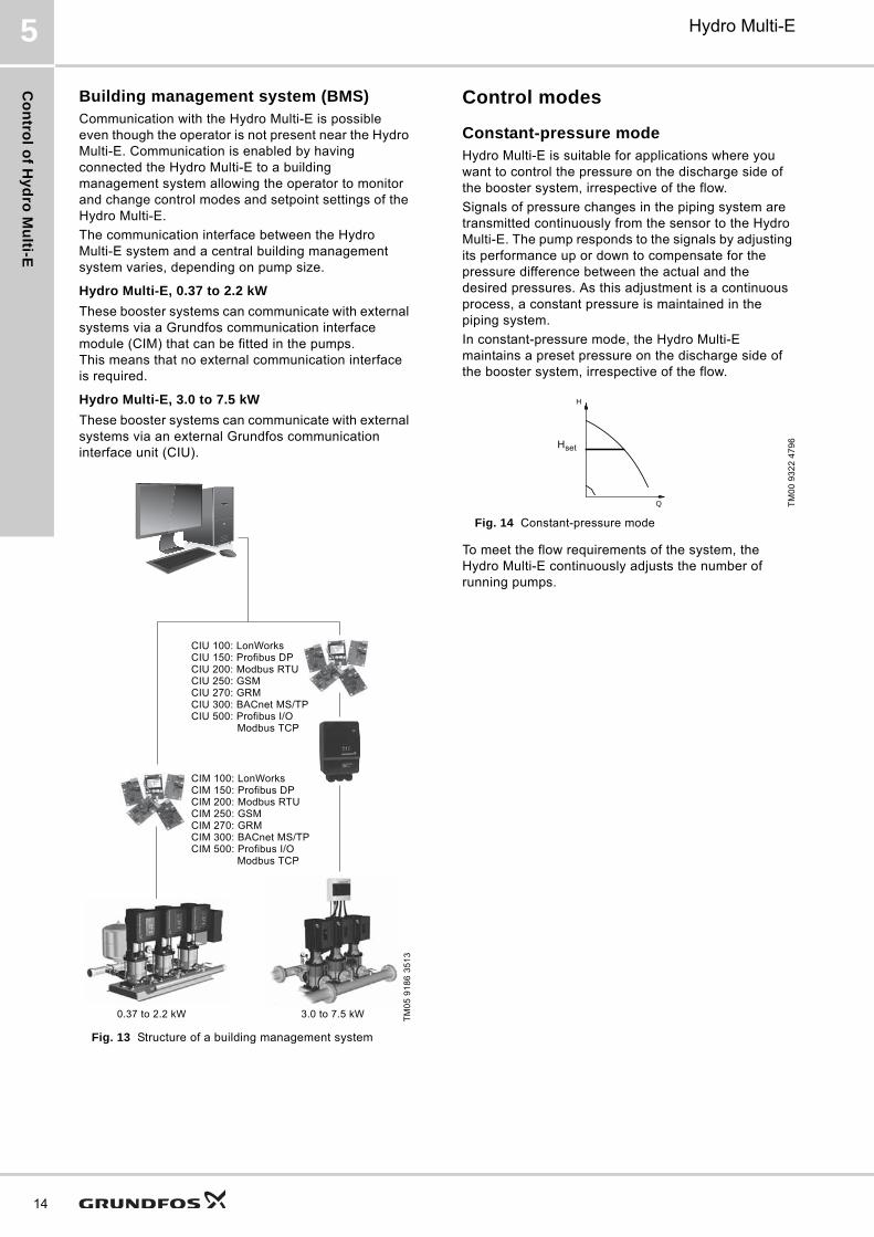
Building management system (BMS)Communication with the Hydro Multi-E is possible even though the operator is not present near the Hydro Multi-E. Communication is enabled by having connected the Hydro Multi-E to a building management system allowing the operator to monitor and change control modes and setpoint settings of the Hydro Multi-E.
The communication interface between the Hydro Multi-E system and a central building management system varies, depending on pump size.
Hydro Multi-E, 0.37 to 2.2 kW
These booster systems can communicate with external systems via a Grundfos communication interface module (CIM) that can be fitted in the pumps. This means that no external communication interface is required.
Hydro Multi-E, 3.0 to 7.5 kW
These booster systems can communicate with external systems via an external Grundfos communication interface unit (CIU).
Fig. 13 Structure of a building management system
Control modes
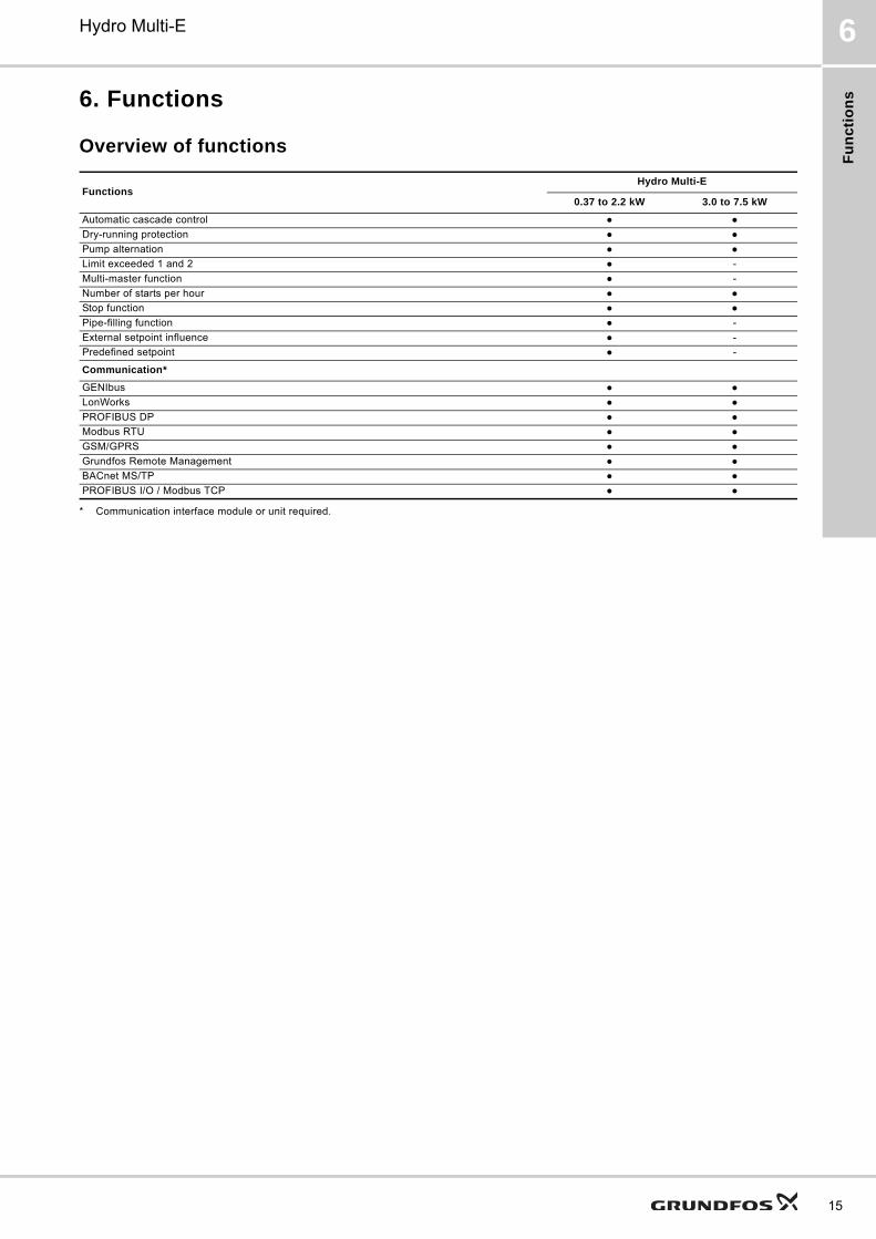
Constant-pressure modeHydro Multi-E is suitable for applications where you want to control the pressure on the discharge side of the booster system, irrespective of the flow.
Signals of pressure changes in the piping system are transmitted continuously from the sensor to the Hydro Multi-E. The pump responds to the signals by adjusting its performance up or down to compensate for the pressure difference between the actual and the desired pressures. As this adjustment is a continuous process, a constant pressure is maintained in the piping system.
In constant-pressure mode, the Hydro Multi-E maintains a preset pressure on the discharge side of the booster system, irrespective of the flow.
Fig. 14 Constant-pressure mode
To meet the flow requirements of the system, the Hydro Multi-E continuously adjusts the number of running pumps.
TM
05
91
86
35
13
CIU 100: LonWorksCIU 150: Profibus DPCIU 200: Modbus RTUCIU 250: GSMCIU 270: GRMCIU 300: BACnet MS/TPCIU 500: Profibus I/O
Modbus TCP
CIM 100: LonWorksCIM 150: Profibus DPCIM 200: Modbus RTUCIM 250: GSMCIM 270: GRMCIM 300: BACnet MS/TPCIM 500: Profibus I/O
Modbus TCP
0.37 to 2.2 kW 3.0 to 7.5 kW
TM
00
93
22
47
96
setH
H
Q
Hset
Fu
nc
tio
ns
Hydro Multi-E 6
6. Functions
Overview of functions
* Communication interface module or unit required.
FunctionsHydro Multi-E
0.37 to 2.2 kW 3.0 to 7.5 kW
Automatic cascade control ● ●
Dry-running protection ● ●
Pump alternation ● ●
Limit exceeded 1 and 2 ● -
Multi-master function ● -
Number of starts per hour ● ●
Stop function ● ●
Pipe-filling function ● -
External setpoint influence ● -
Predefined setpoint ● -
Communication*
GENIbus ● ●
LonWorks ● ●
PROFIBUS DP ● ●
Modbus RTU ● ●
GSM/GPRS ● ●
Grundfos Remote Management ● ●
BACnet MS/TP ● ●
PROFIBUS I/O / Modbus TCP ● ●
15
Fu
nc
tion
s
16
Hydro Multi-E6
Description of functions
Automatic cascade controlCascade control ensures that the performance of the Hydro Multi-E is automatically adapted to the consumption by switching pumps on or off. The system thus runs as energy-efficiently as possible with a constant pressure and only the number of pumps required.
Dry-running protectionThis function is very important as dry running may damage bearings and shaft seals.
The inlet pressure of the system or the water level in a possible tank on the inlet side is monitored. If the inlet pressure or the water level becomes too low, all pumps will be stopped.
Level switches, pressure switches or analog sensors signalling water shortage at a set level can be used. Note: Analog sensors are only available for 0.37 to 2.2 kW systems.
Pump alternationThis function ensures that the operating hours are distributed evenly on the pumps over time.
Limit exceeded 1 and 2
Hydro Multi-E, 0.37 to 2.2 kW
The limit-exceeded function is used for monitoring one or two values/inputs. The function enables different inputs to activate various outputs and alarms/warnings when the signal input has exceeded predetermined limits. The purpose of this function is to monitor parameters which are central for the application. This will enable the pumps to react to possible abnormal operating conditions.
The function can for instance be used for monitoring the following:
• the inlet pressure if an inlet pressure sensor is connected
• the drinking water temperature if a temperature sensor is connected.
Multi-master function
Hydro Multi-E, 0.37 to 2.2 kW
All pumps that have a discharge-pressure sensor connected can function as master pump and control the system. As standard, the Hydro Multi-E is supplied with two discharge-pressure sensors.
As standard, the pump with the lowest number will be the master pump. From factory, the master pump is marked with number 1.
If the master pump is switched off or stopped due to an alarm, one of the other pumps will automatically take over the control of the system. Thereby, the reliability is increased and stop of operation is prevented.
As an option, the system can be supplied with only one discharge-pressure sensor. In that case, the system will stop if the pump or sensor fails.
The system can also be fitted with sensors on all pumps for maximum reliability.
Number of starts per hourThis function limits the number of pump starts and stops per hour.
Each time a pump starts or stops, the system will calculate when the next pump is allowed to start or stop in order not to exceed the permissible number of starts per hour.
This function always allows pumps to be started to meet the requirement, but pump stops will be delayed, if necessary, in order not to exceed the permissible number of starts/stops per hour.
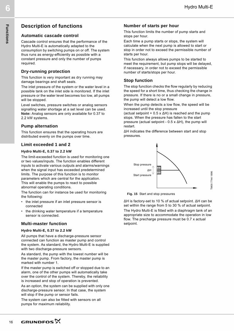
Stop functionThe stop function checks the flow regularly by reducing the speed for a short time, thus checking the change in pressure. If there is no or a small change in pressure, the pump will detect a low flow.
When the pump detects a low flow, the speed will be increased until the stop pressure (actual setpoint + 0.5 x ΔH) is reached and the pump stops. When the pressure has fallen to the start pressure (actual setpoint - 0.5 x ΔH), the pump will restart.
ΔH indicates the difference between start and stop pressures.
Fig. 15 Start and stop pressures
ΔH is factory-set to 10 % of actual setpoint. ΔH can be set within the range from 5 to 30 % of actual setpoint.
The Hydro Multi-E is fitted with a diaphragm tank of an appropriate size to accommodate the operation in low flow. The precharge pressure must be 0.7 x actual setpoint.
TM
00
77
44
18
96
Stop pressure
Start pressure
ΔH
Fu
nc
tio
ns
Hydro Multi-E 6
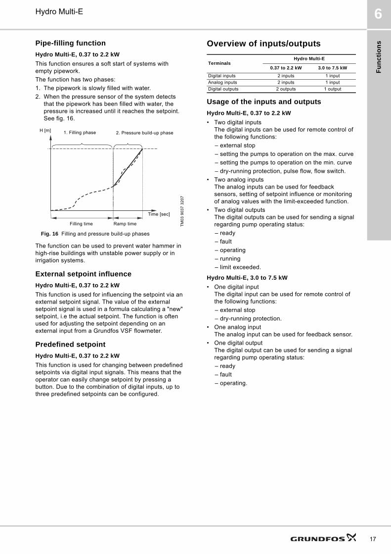
Pipe-filling function
Hydro Multi-E, 0.37 to 2.2 kW
This function ensures a soft start of systems with empty pipework.
The function has two phases:
1. The pipework is slowly filled with water.
2. When the pressure sensor of the system detects that the pipework has been filled with water, the pressure is increased until it reaches the setpoint. See fig. 16.
Fig. 16 Filling and pressure build-up phases
The function can be used to prevent water hammer in high-rise buildings with unstable power supply or in irrigation systems.
External setpoint influence
Hydro Multi-E, 0.37 to 2.2 kW
This function is used for influencing the setpoint via an external setpoint signal. The value of the external setpoint signal is used in a formula calculating a "new" setpoint, i.e the actual setpoint. The function is often used for adjusting the setpoint depending on an external input from a Grundfos VSF flowmeter.
Predefined setpoint
Hydro Multi-E, 0.37 to 2.2 kW
This function is used for changing between predefined setpoints via digital input signals. This means that the operator can easily change setpoint by pressing a button. Due to the combination of digital inputs, up to three predefined setpoints can be configured.
Overview of inputs/outputs
Usage of the inputs and outputs
Hydro Multi-E, 0.37 to 2.2 kW
• Two digital inputsThe digital inputs can be used for remote control of the following functions:
– external stop
– setting the pumps to operation on the max. curve
– setting the pumps to operation on the min. curve
– dry-running protection, pulse flow, flow switch.
• Two analog inputsThe analog inputs can be used for feedback sensors, setting of setpoint influence or monitoring of analog values with the limit-exceeded function.
• Two digital outputsThe digital outputs can be used for sending a signal regarding pump operating status:
– ready
– fault
– operating
– running
– limit exceeded.
Hydro Multi-E, 3.0 to 7.5 kW
• One digital inputThe digital input can be used for remote control of the following functions:
– external stop
– dry-running protection.
• One analog inputThe analog input can be used for feedback sensor.
• One digital outputThe digital output can be used for sending a signal regarding pump operating status:
– ready
– fault
– operating.
TM
03
90
37
32
07
1. Filling phase 2. Pressure build-up phaseH [m]
Filling time Ramp time
Time [sec]
TerminalsHydro Multi-E
0.37 to 2.2 kW 3.0 to 7.5 kW
Digital inputs 2 inputs 1 input
Analog inputs 2 inputs 1 input
Digital outputs 2 outputs 1 output
17
Sizin
g
18
Hydro Multi-E7
7. Sizing
To ensure that the system is operating as efficiently as possible, it is important that the system is sized so that the performance meets the requirements of the application.
Note: Local legislation must always be taken into account.
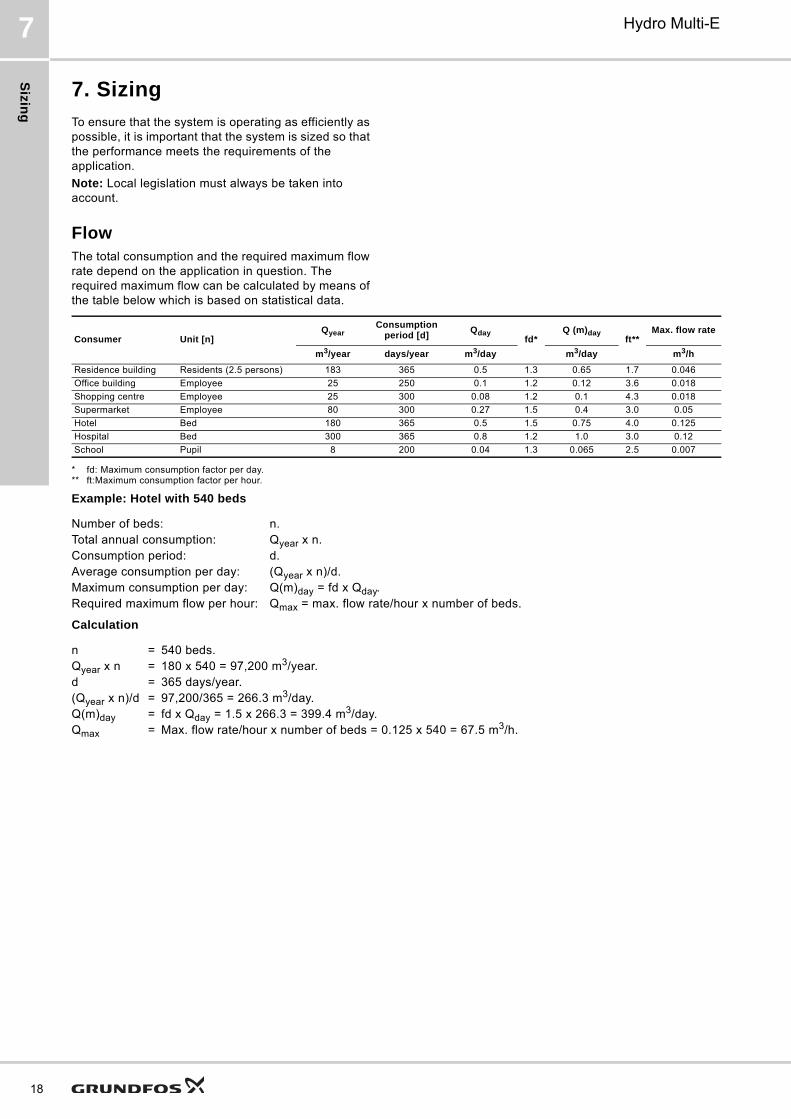
FlowThe total consumption and the required maximum flow rate depend on the application in question. The required maximum flow can be calculated by means of the table below which is based on statistical data.
* fd: Maximum consumption factor per day.** ft:Maximum consumption factor per hour.
Example: Hotel with 540 beds
Calculation
Consumer Unit [n]Qyear
Consumption period [d]
Qdayfd*
Q (m)dayft**
Max. flow rate
m3/year days/year m3/day m3/day m3/h
Residence building Residents (2.5 persons) 183 365 0.5 1.3 0.65 1.7 0.046
Office building Employee 25 250 0.1 1.2 0.12 3.6 0.018
Shopping centre Employee 25 300 0.08 1.2 0.1 4.3 0.018
Supermarket Employee 80 300 0.27 1.5 0.4 3.0 0.05
Hotel Bed 180 365 0.5 1.5 0.75 4.0 0.125
Hospital Bed 300 365 0.8 1.2 1.0 3.0 0.12
School Pupil 8 200 0.04 1.3 0.065 2.5 0.007
Number of beds: n.Total annual consumption: Qyear x n.Consumption period: d.Average consumption per day: (Qyear x n)/d.Maximum consumption per day: Q(m)day = fd x Qday.Required maximum flow per hour: Qmax = max. flow rate/hour x number of beds.
n = 540 beds.Qyear x n = 180 x 540 = 97,200 m3/year.d = 365 days/year.(Qyear x n)/d = 97,200/365 = 266.3 m3/day.Q(m)day = fd x Qday = 1.5 x 266.3 = 399.4 m3/day.Qmax = Max. flow rate/hour x number of beds = 0.125 x 540 = 67.5 m3/h.
Siz
ing
Hydro Multi-E 7
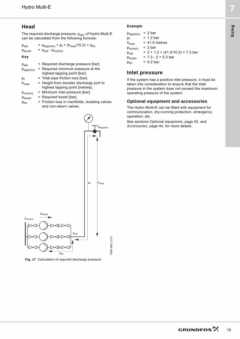
HeadThe required discharge pressure, pset, of Hydro Multi-E can be calculated from the following formula:
Key
Fig. 17 Calculation of required discharge pressure
Example
Inlet pressureIf the system has a positive inlet pressure, it must be taken into consideration to ensure that the total pressure in the system does not exceed the maximum operating pressure of the system.
Optional equipment and accessoriesThe Hydro Multi-E can be fitted with equipment for communication, dry-running protection, emergency operation, etc.
See sections Optional equipment, page 42, and Accessories, page 44, for more details.
pset = ptap(min) + pf + (hmax/10.2) + pfmpboost = pset - pin(min)
pset = Required discharge pressure [bar].ptap(min) = Required minimum pressure at the
highest tapping point [bar].pf = Total pipe friction loss [bar].hmax = Height from booster discharge port to
highest tapping point [metres].pin(min) = Minimum inlet pressure [bar].pboost = Required boost [bar].pfm = Friction loss in manifolds, isolating valves
and non-return valves.T
M0
5 8
82
7 2
71
3
hmaxpf
pboost
pin(min)
pset
pfm
ptap(min)
ptap(min) = 2 barpf = 1.2 barhmax = 41.5 metrespin(min) = 2 barpset = 2 + 1.2 + (41.5/10.2) = 7.3 barpboost = 7.3 - 2 = 5.3 barpfm = 0.2 bar.
19
Sizin
g
20
Hydro Multi-E7
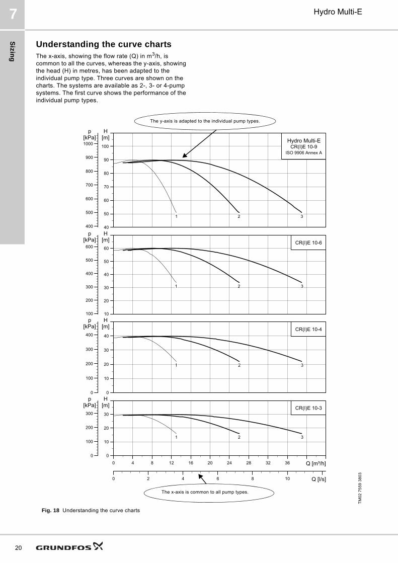
Understanding the curve chartsThe x-axis, showing the flow rate (Q) in m3/h, is common to all the curves, whereas the y-axis, showing the head (H) in metres, has been adapted to the individual pump type. Three curves are shown on the charts. The systems are available as 2-, 3- or 4-pump systems. The first curve shows the performance of the individual pump types.
Fig. 18 Understanding the curve charts
TM
02
75
59
38
03
0 4 8 12 16 20 24 28 32 36 Q [m³/h]0
10
20
30
[m]H
0 2 4 6 8 10 Q [l/s]
0
100
200
300
[kPa]p
CR(I)E 10-3
1 2 3
0 4 8 12 16 20 24 28 32 36 Q [m³/h]
0
10
20
30
40
[m]H
0
100
200
300
400
[kPa]p
CR(I)E 10-4
1 2 3
0 4 8 12 16 20 24 28 32 36 Q [m³/h]
10
20
30
40
50
60
[m]H
100
200
300
400
500
600[kPa]
pCR(I)E 10-6
1 2 3
0 4 8 12 16 20 24 28 32 36 Q [m³/h]
40
50
60
70
80
90
100
[m]H
400
500
600
700
800
900
1000[kPa]
p
Hydro Multi-ECR(I)E 10-9
ISO 9906 Annex A
1 2 3
The x-axis is common to all pump types.
The y-axis is adapted to the individual pump types.
Siz
ing
Hydro Multi-E 7
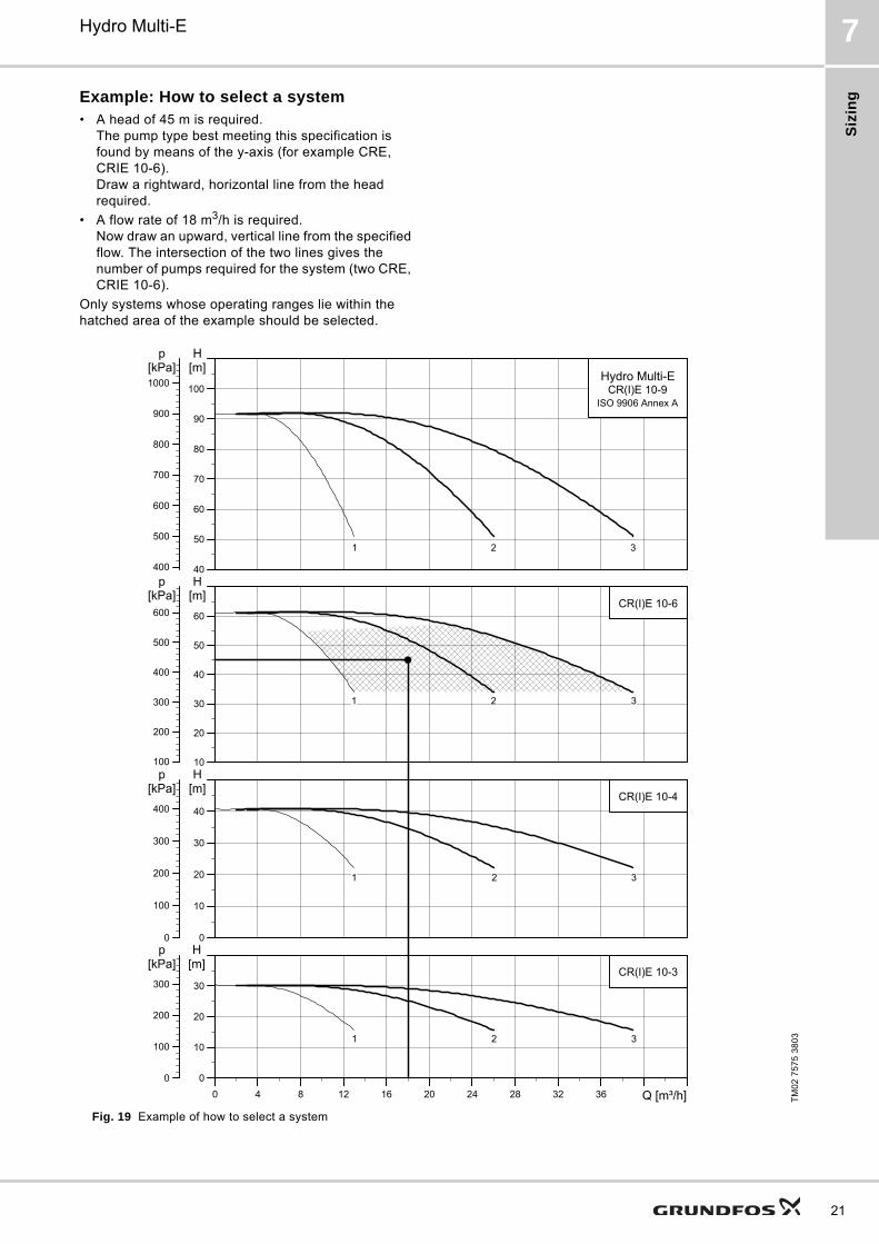
Example: How to select a system• A head of 45 m is required.
The pump type best meeting this specification is found by means of the y-axis (for example CRE, CRIE 10-6). Draw a rightward, horizontal line from the head required.
• A flow rate of 18 m3/h is required.Now draw an upward, vertical line from the specified flow. The intersection of the two lines gives the number of pumps required for the system (two CRE, CRIE 10-6).
Only systems whose operating ranges lie within the hatched area of the example should be selected.
Fig. 19 Example of how to select a system
TM
02
75
75
38
03
0 4 8 12 16 20 24 28 32 36 Q [m³/h]
0
10
20
30
H[m]
0
100
200
300
p[kPa]
CR(I)E 10-3
1 2 3
0 4 8 12 16 20 24 28 32 36 Q [m³/h]
0
10
20
30
40
H[m]
0
100
200
300
400
p[kPa]
CR(I)E 10-4
1 2 3
0 4 8 12 16 20 24 28 32 36 Q [m³/h]
10
20
30
40
50
60
H[m]
100
200
300
400
500
600
p[kPa]
CR(I)E 10-6
1 2 3
0 4 8 12 16 20 24 28 32 36 Q [m³/h]
40
50
60
70
80
90
100
H[m]
400
500
600
700
800
900
1000
p[kPa]
Hydro Multi-ECR(I)E 10-9
ISO 9906 Annex A
1 2 3
21
Pe
rform
an
ce
cu
rve
s a
nd
tec
hn
ica
l da
ta
22
8
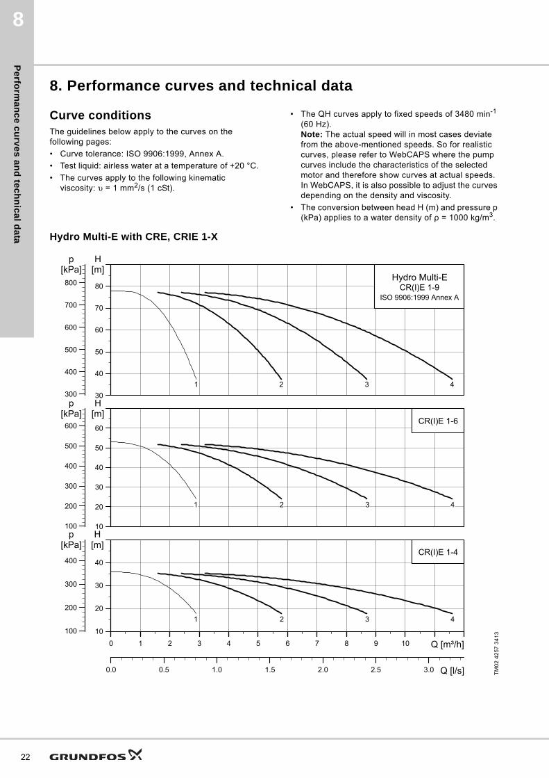
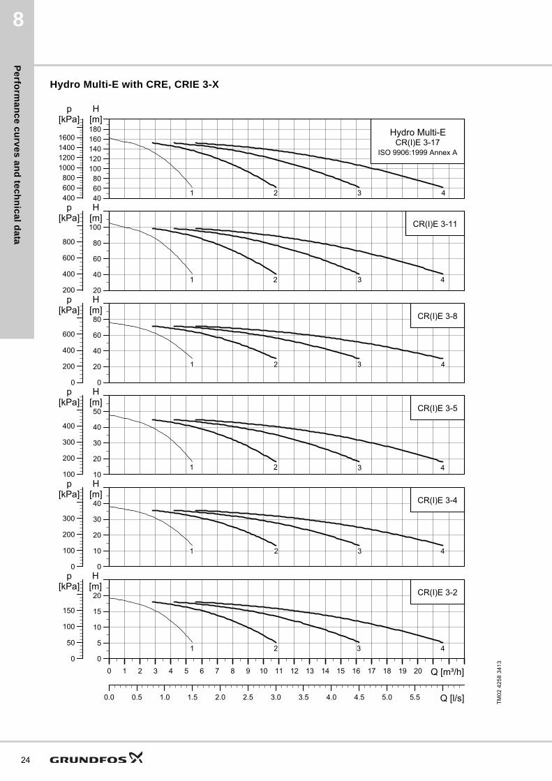
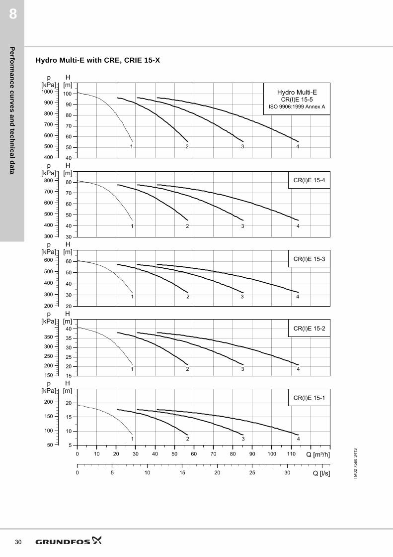
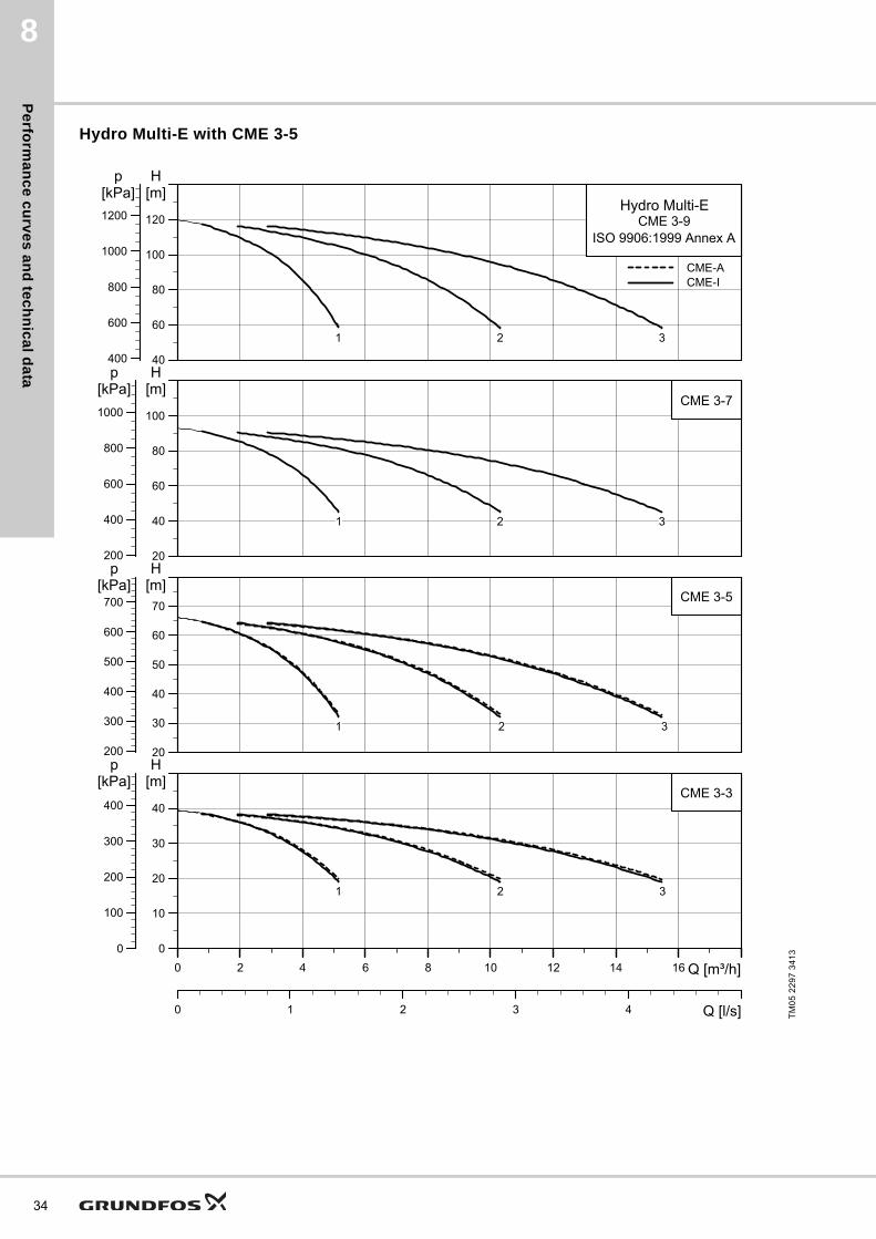
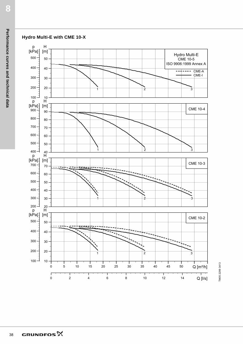
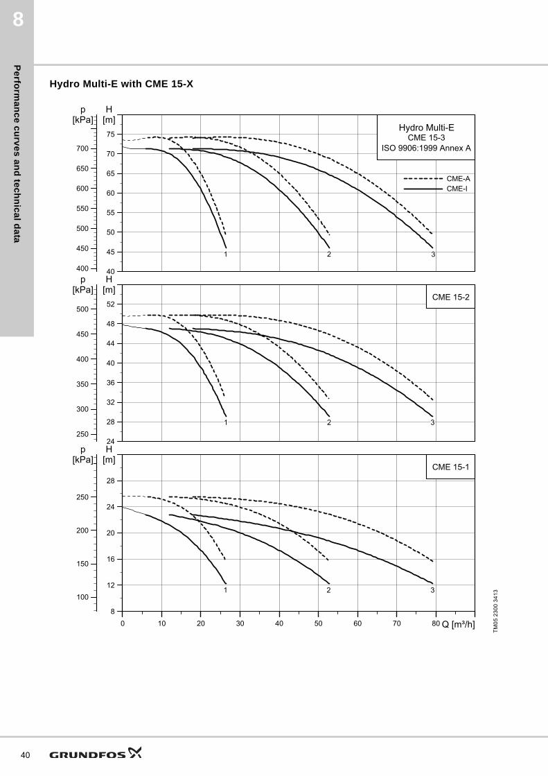
8. Performance curves and technical data
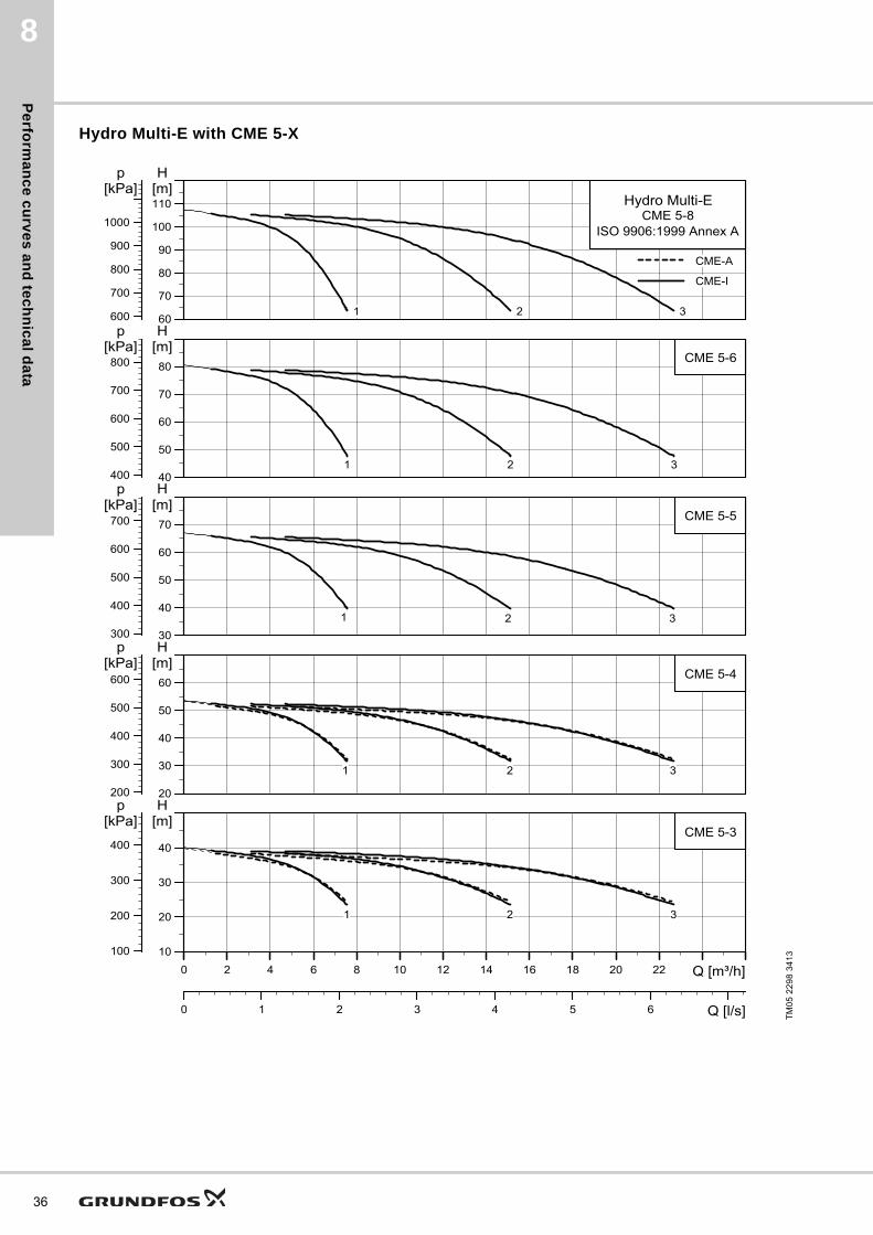
Curve conditionsThe guidelines below apply to the curves on the following pages:
• Curve tolerance: ISO 9906:1999, Annex A.
• Test liquid: airless water at a temperature of +20 °C.
• The curves apply to the following kinematic viscosity: υ = 1 mm2/s (1 cSt).
• The QH curves apply to fixed speeds of 3480 min-1 (60 Hz). Note: The actual speed will in most cases deviate from the above-mentioned speeds. So for realistic curves, please refer to WebCAPS where the pump curves include the characteristics of the selected motor and therefore show curves at actual speeds. In WebCAPS, it is also possible to adjust the curves depending on the density and viscosity.
• The conversion between head H (m) and pressure p (kPa) applies to a water density of ρ = 1000 kg/m3.
Hydro Multi-E with CRE, CRIE 1-X
TM
02
42
57
34
13
0 1 2 3 4 5 6 7 8 9 10 Q [m³/h]
10
20
30
40
H[m]
0.0 0.5 1.0 1.5 2.0 2.5 3.0 Q [l/s]
100
200
300
400
p[kPa]
CR(I)E 1-4
4321
0 1 2 3 4 5 6 7 8 9 10 Q [m³/h]
10
20
30
40
50
60
H[m]
100
200
300
400
500
600
p[kPa]
CR(I)E 1-6
4321
0 1 2 3 4 5 6 7 8 9 10 Q [m³/h]
30
40
50
60
70
80
H[m]
300
400
500
600
700
800
p[kPa]
CR(I)E 1-9Hydro Multi-E
ISO 9906:1999 Annex A
4321
Pe
rfo
rma
nc
e c
urv
es
an
d t
ec
hn
ica
l d
ata
8
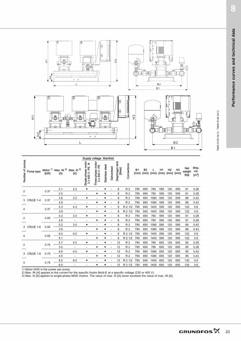
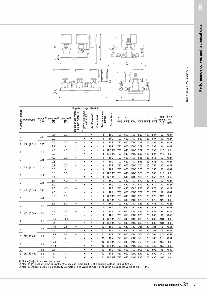
1) Motor [kW] is the power per pump.2) Max. IN [A] applies to the current for the specific Hydro Multi-E at a specific voltage (230 or 400 V).3) Max. I0 [A] applies to single-phase MGE motors. The value of max. I0 [A] never exceeds the value of max. IN [A].
TM
05
91
50
34
13
- T
M0
5 9
14
8 3
41
3
2 31
21
Num
ber o
f pum
ps
Pump type Motor 1)
[kW]Max. IN 2)
[A]Max. I0 3)
[A]
Supply voltage Manifold
Dia
phra
gm ta
nk[li
tres]
Con
nect
ions
B1[mm]
B2[mm]
L[mm]
H1[mm]
H2[mm]
H3[mm]
Netweight
[kg]
Ship.vol.[m3]
Sing
le-p
hase
mot
or3
x 40
0 V.
PE.
N
Thre
e-ph
ase
mot
or3
x 40
0 V.
PE
Stai
nles
s st
eel
Gal
vani
sed
2
CR(I)E 1-4
0.373.1 2.2 ● - ● - 8 R 2 790 650 760 559 120 559 61 0.282.0 - - ● ● - 8 R 2 790 650 760 559 120 559 61 0.28
3 0.373.8 2.2 ● - ● - 8 R 2 790 650 1080 559 120 559 89 0.432.9 - - ● ● - 8 R 2 790 650 1080 559 120 559 89 0.43
4 0.374.3 4.3 ● - ● - 8 R 2 1/2 790 645 1400 559 120 559 122 0.63.9 - - ● ● - 8 R 2 1/2 790 645 1400 559 120 559 122 0.6
2
CR(I)E 1-6
0.554.3 3.0 ● - ● - 8 R 2 790 650 760 595 120 595 61 0.282.5 - - ● ● - 8 R 2 790 650 760 595 120 595 61 0.28
3 0.555.2 3.0 ● - ● - 8 R 2 790 650 1080 595 120 595 89 0.433.8 - - ● ● - 8 R 2 790 650 1080 595 120 595 89 0.43
4 0.556.0 6.0 ● - ● - 8 R 2 1/2 790 650 1400 595 120 595 122 0.65.1 - - ● ● - 8 R 2 1/2 790 650 1400 595 120 595 122 0.6
2
CR(I)E 1-9
0.755.7 4.0 ● - ● - 12 R 2 790 650 760 655 120 655 65 0.283.0 - - ● ● - 12 R 2 790 650 760 655 120 655 65 0.28
3 0.756.9 4.0 ● - ● - 12 R 2 790 650 1080 655 120 655 95 0.434.5 - - ● ● - 12 R 2 790 650 1080 655 120 655 95 0.43
4 0.758.0 8.0 ● - ● - 12 R 2 1/2 790 645 1400 655 120 655 130 0.66.0 - - ● ● - 12 R 2 1/2 790 645 1400 655 120 655 130 0.6
23
Pe
rform
an
ce
cu
rve
s a
nd
tec
hn
ica
l da
ta
24
8
Hydro Multi-E with CRE, CRIE 3-X
TM
02
42
58
34
13
0 1 2 3 4 5 6 7 8 9 10 11 12 13 14 15 16 17 18 19 20 Q [m³/h]
0
5
10
15
20
H[m]
0.0 0.5 1.0 1.5 2.0 2.5 3.0 3.5 4.0 4.5 5.0 5.5 Q [l/s]
0
50
100
150
p[kPa]
CR(I)E 3-2
4321
0 1 2 3 4 5 6 7 8 9 10 11 12 13 14 15 16 17 18 19 20 Q [m³/h]
0
10
20
30
40
H[m]
0
100
200
300
p[kPa]
CR(I)E 3-4
4321
0 1 2 3 4 5 6 7 8 9 10 11 12 13 14 15 16 17 18 19 20 Q [m³/h]
10
20
30
40
50
H[m]
100
200
300
400
p[kPa]
CR(I)E 3-5
4321
0 1 2 3 4 5 6 7 8 9 10 11 12 13 14 15 16 17 18 19 20 Q [m³/h]
0
20
40
60
80
H[m]
0
200
400
600
p[kPa]
CR(I)E 3-8
4321
0 1 2 3 4 5 6 7 8 9 10 11 12 13 14 15 16 17 18 19 20 Q [m³/h]
20
40
60
80
100[m]H
200
400
600
800
[kPa]p
CR(I)E 3-11
4321
0 1 2 3 4 5 6 7 8 9 10 11 12 13 14 15 16 17 18 19 20 Q [m³/h]
406080
100120140160180[m]H
400600800
1000120014001600
[kPa]p
Hydro Multi-ECR(I)E 3-17
ISO 9906:1999 Annex A
4321
Pe
rfo
rma
nc
e c
urv
es
an
d t
ec
hn
ica
l d
ata
8
1) Motor [kW] is the power per pump.2) Max. IN [A] applies to the current for the specific Hydro Multi-E at a specific voltage (230 or 400 V).3) Max. I0 [A] applies to single-phase MGE motors. The value of max. I0 [A] never exceeds the value of max. IN [A].
TM
05
91
50
34
13
- T
M0
5 9
14
8 3
41
3
2 31
21
Num
ber o
f pum
ps
Pump type Motor 1)
[kW]Max. IN 2)
[A]Max. I0 3)
[A]
Supply voltage Manifold
Dia
phra
gm ta
nk[li
tres]
Con
nect
ions
B1[mm]
B2[mm]
L[mm]
H1[mm]
H2[mm]
H3[mm]
Netweight
[kg]
Ship.vol.[m3]
Sing
le-p
hase
mot
or3
x 40
0 V.
PE.
N
Thre
e-ph
ase
mot
or3
x 40
0 V.
PE
Stai
nles
s st
eel
Gal
vani
sed
2
CR(I)E 3-2
0.373.1 2.2 ● - ● - 8 R 2 790 650 760 537 120 537 59 0.272.0 - - ● ● - 8 R 2 790 650 760 537 120 537 59 0.27
3 0.373.8 2.2 ● - ● - 8 R 2 790 650 1080 537 120 537 86 0.412.9 - - ● ● - 8 R 2 790 650 1080 537 120 537 86 0.41
4 0.374.3 4.3 ● - ● - 8 R 2 1/2 790 645 1400 537 120 537 118 0.63.9 - - ● ● - 8 R 2 1/2 790 645 1400 537 120 537 118 0.6
2
CR(I)E 3-4
0.554.3 3.0 ● - ● - 8 R 2 790 650 760 555 120 555 57 0.272.5 - - ● ● - 8 R 2 790 650 760 555 120 555 57 0.27
3 0.555.2 3.0 ● - ● - 8 R 2 790 650 1080 555 120 555 67 0.413.8 - - ● ● - 8 R 2 790 650 1080 555 120 555 67 0.41
4 0.556.0 6.0 ● - ● - 8 R 2 1/2 790 645 1400 555 120 555 117 0.65.1 - - ● ● - 8 R 2 1/2 790 645 1400 555 120 555 117 0.6
2
CR(I)E 3-5
0.755.7 4.0 ● - ● - 8 R 2 790 650 760 579 120 579 63 0.273.0 - - ● ● - 8 R 2 790 650 760 579 120 579 63 0.27
3 0.756.9 4.0 ● - ● - 8 R 2 790 650 1080 579 120 579 92 0.414.5 - - ● ● - 8 R 2 790 650 1080 579 120 579 92 0.41
4 0.758.0 8.0 ● - ● - 8 R 2 1/2 790 645 1400 579 120 579 128 0.66.0 - - ● ● - 8 R 2 1/2 790 645 1400 579 120 579 128 0.6
2
CR(I)E 3-8
1.18.1 5.7 ● - ● - 8 R 2 790 650 760 633 120 633 67 0.284.2 - - ● ● - 8 R 2 790 650 760 633 120 633 67 0.28
3 1.19.9 5.7 ● - ● - 8 R 2 790 650 1080 633 120 633 98 0.436.3 - - ● ● - 8 R 2 790 650 1080 633 120 633 98 0.43
4 1.111.4 11.4 ● - ● - 8 R 2 1/2 790 645 1400 633 120 633 134 0.68.4 - - ● ● - 8 R 2 1/2 790 645 1400 633 120 633 134 0.6
2
CR(I)E 3-11
1.511.0 7.8 ● - ● - 12 R 2 790 650 760 763 120 763 79 0.335.6 - - ● ● - 12 R 2 790 650 760 763 120 763 79 0.33
3 1.513.5 7.8 ● - ● - 12 R 2 790 650 1080 763 120 763 116 0.518.5 - - ● ● - 12 R 2 790 650 1080 763 120 763 116 0.51
4 1.515.6 15.6 ● - ● - 12 R 2 1/2 790 645 1400 763 120 763 158 0.611.3 - - ● ● - 12 R 2 1/2 790 645 1400 763 120 763 158 0.6
2CR(I)E 3-17
2.2 8.1 - - ● ● - 12 R 2 830 650 760 896 120 896 95 0.393 2.2 12.1 - - ● ● - 12 R 2 830 650 1080 896 120 896 140 0.64 2.2 16.1 - - ● ● - 12 R 2 1/2 790 645 1400 896 120 896 190 0.6
25

Pe
rform
an
ce
cu
rve
s a
nd
tec
hn
ica
l da
ta
26
8
Hydro Multi-E with CRE, CRIE 5-X
TM
02
42
59
34
13
0 2 4 6 8 10 12 14 16 18 20 22 24 26 28 30 32 34 36 38 Q [m³/h]
0
5
10
15
20
H[m]
0 1 2 3 4 5 6 7 8 9 10 11 Q [l/s]
0
50
100
150
p[kPa]
CR(I)E 5-2
4321
0 2 4 6 8 10 12 14 16 18 20 22 24 26 28 30 32 34 36 38 Q [m³/h]
0
10
20
30
40
H[m]
0
100
200
300
p[kPa]
CR(I)E 5-4
4321
0 2 4 6 8 10 12 14 16 18 20 22 24 26 28 30 32 34 36 38 Q [m³/h]
10
20
30
40
50
H[m]
100
200
300
400
p[kPa]
CR(I)E 5-5
4321
0 2 4 6 8 10 12 14 16 18 20 22 24 26 28 30 32 34 36 38 Q [m³/h]
20
40
60
80
100
H[m]
200
400
600
800
p[kPa]
CR(I)E 5-9
4321
0 2 4 6 8 10 12 14 16 18 20 22 24 26 28 30 32 34 36 38 Q [m³/h]
40
60
80
100
120[m]H
400
600
800
1000
[kPa]p
CR(I)E 5-12
4321
0 2 4 6 8 10 12 14 16 18 20 22 24 26 28 30 32 34 36 38 Q [m³/h]
406080
100120140160180[m]H
400600800
1000120014001600
[kPa]p
Hydro Multi-ECR(I)E 5-16
ISO 9906:1999 Annex A
4321
Pe
rfo
rma
nc
e c
urv
es
an
d t
ec
hn
ica
l d
ata
8
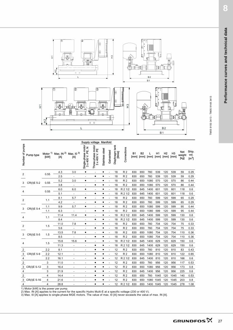
1) Motor [kW] is the power per pump.2) Max. IN [A] applies to the current for the specific Hydro Multi-E at a specific voltage (230 or 400 V).3) Max. I0 [A] applies to single-phase MGE motors. The value of max. I0 [A] never exceeds the value of max. IN [A].
TM
05
91
50
34
13
- T
M0
5 9
14
8 3
41
3
2 31
21
Num
ber o
f pum
ps
Pump type Motor 1)
[kW]Max. IN 2)
[A]Max. I0 3)
[A]
Supply voltage Manifold
Dia
phra
gm ta
nk[li
tres]
Con
nect
ions
B1[mm]
B2[mm]
L[mm]
H1[mm]
H2[mm]
H3[mm]
Netweight
[kg]
Ship.vol.[m3]
Sing
le-p
hase
mot
or3
x 40
0 V.
PE.
N
Thre
e-ph
ase
mot
or3
x 40
0 V.
PE
Stai
nles
s st
eel
Gal
vani
sed
2
CR(I)E 5-2
0.554.3 3.0 ● - ● - 18 R 2 830 650 760 539 120 539 59 0.292.5 - - ● ● - 18 R 2 830 650 760 539 120 539 59 0.29
3 0.555.2 3.0 ● - ● - 18 R 2 830 650 1080 570 120 570 86 0.443.8 - - ● ● - 18 R 2 830 650 1080 570 120 570 86 0.44
4 0.556.0 6.0 ● - ● - 18 R 2 1/2 830 645 1400 601 120 601 118 0.65.1 - - ● ● - 18 R 2 1/2 830 645 1400 601 120 601 118 0.6
2
CR(I)E 5-4
1.18.1 5.7 ● - ● - 18 R 2 830 650 760 599 120 599 65 0.294.2 - - ● ● - 18 R 2 830 650 760 599 120 599 65 0.29
31.1 9.9 5.7 ● - ● - 18 R 2 830 650 1080 599 120 599 95 0.441.1 6.3 - - ● ● - 18 R 2 830 650 1080 599 120 599 95 0.44
4 1.111.4 11.4 ● - ● - 18 R 2 1/2 830 645 1400 599 120 599 130 0.68.4 - - ● ● - 18 R 2 1/2 830 645 1400 599 120 599 130 0.6
2
CR(I)E 5-5
1.511.0 7.8 ● - ● - 18 R 2 830 650 760 704 120 704 75 0.335.6 - - ● ● - 18 R 2 830 650 760 704 120 704 75 0.33
3 1.513.5 7.8 ● - ● - 18 R 2 830 650 1080 704 120 704 110 0.368.5 - - ● ● - 18 R 2 830 650 1080 704 120 704 110 0.36
4 1.515.6 15.6 ● - ● - 18 R 2 1/2 830 645 1400 629 120 629 150 0.611.3 - - ● ● - 18 R 2 1/2 830 645 1400 629 120 629 150 0.6
2CR(I)E 5-9
2.2 8.1 - - ● ● - 12 R 2 830 650 760 810 120 810 83 0.433 2.2 12.1 - - ● ● - 12 R 2 830 650 1080 810 120 810 122 0.654 2.2 16.1 - - ● ● - 12 R 2 1/2 830 645 1400 810 120 810 166 0.62
CR(I)E 5-123 11.0 - - ● ● - 12 R 2 830 650 760 956 120 956 117 0.53
3 3 16.4 - - ● ● - 12 R 2 830 650 1080 956 120 956 173 0.84 3 21.9 - - ● ● - 12 R 2 830 645 1400 956 120 956 225 0.62
CR(I)E 5-164 14.4 - - ● ● - 12 R 2 830 650 760 1045 120 1045 140 0.53
3 4 21.6 - - ● ● - 12 R 2 830 650 1080 1045 120 1045 203 0.84 4 28.8 - - ● ● - 12 R 2 1/2 830 650 1400 1045 120 1045 278 1.08
27

Pe
rform
an
ce
cu
rve
s a
nd
tec
hn
ica
l da
ta
28
8
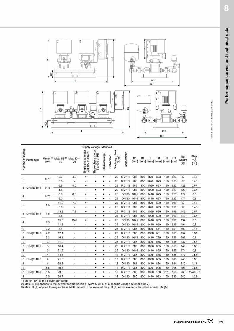
Hydro Multi-E with CRE, CRIE 10-X
TM
02
75
59
34
13
0 5 10 15 20 25 30 35 40 45 50 55 60 Q [m³/h]
0
5
10
15
H[m]
0 2 4 6 8 10 12 14 16 Q [l/s]
0
50
100
150
p[kPa]
CR(I)E 10-1
4321
0 5 10 15 20 25 30 35 40 45 50 55 60 Q [m³/h]
10
15
20
25
30
H[m]
100
150
200
250
p[kPa]
CR(I)E 10-2
4321
0 5 10 15 20 25 30 35 40 45 50 55 60 Q [m³/h]
10
20
30
40
50
H[m]
100
200
300
400
p[kPa]
CR(I)E 10-3
4321
0 5 10 15 20 25 30 35 40 45 50 55 60 Q [m³/h]
20
40
60
80
H[m]
200
400
600
800
p[kPa]
CR(I)E 10-5
4321
0 5 10 15 20 25 30 35 40 45 50 55 60 Q [m³/h]
20
40
60
80
100[m]H
200
400
600
800
[kPa]p
CR(I)E 10-6
4321
0 5 10 15 20 25 30 35 40 45 50 55 60 Q [m³/h]
40
80
120
160
[m]H
400600800
1000120014001600
[kPa]p
Hydro Multi-ECR(I)E 10-9
ISO 9906:1999 Annex A
4321
Pe
rfo
rma
nc
e c
urv
es
an
d t
ec
hn
ica
l d
ata
8
1) Motor [kW] is the power per pump.2) Max. IN [A] applies to the current for the specific Hydro Multi-E at a specific voltage (230 or 400 V).3) Max. I0 [A] applies to single-phase MGE motors. The value of max. I0 [A] never exceeds the value of max. IN [A].
TM
05
91
50
34
13
- T
M0
5 9
14
8 3
41
3
2 31
21
Num
ber o
f pum
ps
Pump type Motor 1)
[kW]Max. IN 2)
[A]Max. I0 3)
[A]
Supply voltage Manifold
Dia
phra
gm ta
nk[li
tres]
Con
nect
ions
B1[mm]
B2[mm]
L[mm]
H1[mm]
H2[mm]
H3[mm]
Netweight
[kg]
Ship.vol.[m3]
Sing
le-p
hase
mot
or3
x 40
0 V.
PE.
N
Thre
e-ph
ase
mot
or3
x 40
0 V.
PE
Stai
nles
s st
eel
Gal
vani
sed
2
CR(I)E 10-1
0.755.7 4.0 ● - ● - 25 R 2 1/2 985 800 820 623 150 623 87 0.453.0 - - ● ● - 25 R 2 1/2 985 800 820 623 150 623 87 0.45
3 0.756.9 4.0 ● - ● - 25 R 2 1/2 985 800 1090 623 150 623 128 0.674.5 - - ● ● - 25 R 2 1/2 985 800 1090 623 150 623 128 0.67
4 0.758.0 8.0 ● - ● - 25 DN 80 1045 800 1410 623 150 623 174 0.86.0 - - ● ● - 25 DN 80 1045 800 1410 623 150 623 174 0.8
2
CR(I)E 10-1
1.511.0 7.8 ● - ● - 25 R 2 1/2 985 800 820 699 150 699 97 0.455.6 - - ● ● - 25 R 2 1/2 985 800 820 699 150 699 97 0.45
3 1.513.5 7.8 ● - ● - 25 R 2 1/2 985 800 1090 699 150 699 143 0.678.5 - - ● ● - 25 R 2 1/2 985 800 1090 699 150 699 143 0.67
4 1.515.6 15.6 ● - ● - 25 DN 80 1045 800 1410 699 150 699 194 0.811.3 - - ● ● - 25 DN 80 1045 800 1410 699 150 699 194 0.8
2CR(I)E 10-3
2.2 8.1 - - ● ● - 25 R 2 1/2 985 800 820 651 150 651 103 0.483 2.2 12.1 - - ● ● - 25 R 2 1/2 985 800 1090 651 150 651 152 0.674 2.2 16.1 - - ● ● - 25 DN 80 1045 800 1410 729 150 729 206 0.82
CR(I)E 10-53 11.0 - - ● ● - 25 R 2 1/2 985 800 820 855 150 855 137 0.58
3 3 16.4 - - ● ● - 25 R 2 1/2 985 800 1090 855 150 855 143 0.864 3 21.9 - - ● ● - 25 DN 80 1045 800 1410 855 150 855 274 0.82
CR(I)E 10-64 14.4 - - ● ● - 12 R 2 1/2 985 800 820 885 150 885 177 0.58
3 4 21.6 - - ● ● - 12 R 2 1/2 985 800 1090 885 150 885 243 0.864 4 28.8 - - ● ● - 12 DN 80 984 800 1410 884 150 884 310 1.142
CR(I)E 10-95.5 19.4 - - ● ● - 12 R 2 1/2 985 800 820 995 150 995 193 0.65
3 5.5 29.0 - - ● ● - 12 R 2 1/2 800 995 1090 150 1570 150 266 #VALUE!4 5.5 38.7 - - ● ● - 12 DN 80 985 800 1410 993 150 993 340 1.28
29
Pe
rform
an
ce
cu
rve
s a
nd
tec
hn
ica
l da
ta
30
8
Hydro Multi-E with CRE, CRIE 15-X
TM
02
75
60
34
13
0 10 20 30 40 50 60 70 80 90 100 110 Q [m³/h]
5
10
15
20
H[m]
0 5 10 15 20 25 30 Q [l/s]
50
100
150
200
p[kPa]
CR(I)E 15-1
4321
0 10 20 30 40 50 60 70 80 90 100 110 Q [m³/h]
20
30
40
50
60
H[m]
200
300
400
500
600
p[kPa]
CR(I)E 15-3
4321
0 10 20 30 40 50 60 70 80 90 100 110 Q [m³/h]
30
40
50
60
70
80
[m]H
300
400
500
600
700
800[kPa]
p
CR(I)E 15-4
4321
0 10 20 30 40 50 60 70 80 90 100 110 Q [m³/h]
40
50
60
70
80
90
100
[m]H
400
500
600
700
800
900
1000[kPa]
p
Hydro Multi-ECR(I)E 15-5
ISO 9906:1999 Annex A
4321
0 10 20 30 40 50 60 70 80 90 100 110 Q [m³/h]
15
20
25
30
35
40[m]H
150
200
250
300
350
[kPa]p
CR(I)E 15-2
4321
Pe
rfo
rma
nc
e c
urv
es
an
d t
ec
hn
ica
l d
ata
8
1) Motor [kW] is the power per pump.2) Max. IN [A] applies to the current for the specific Hydro Multi-E at a specific voltage (230 or 400 V).3) Max. I0 [A] applies to single-phase MGE motors. The value of max. I0 [A] never exceeds the value of max. IN [A].
TM
05
91
50
34
13
- T
M0
5 9
14
8 3
41
3
2 31
21
Num
ber o
f pum
ps
Pump type Motor 1)
[kW]Max. IN 2)
[A]Max. I0 3)
[A]
Supply voltage Manifold
Dia
phra
gm ta
nk[li
tres]
Con
nect
ions
B1[mm]
B2[mm]
L[mm]
H1[mm]
H2[mm]
H3[mm]
Netweight
[kg]
Ship.vol.[m3]
Sing
le-p
hase
mot
or3
x 40
0 V.
PE.
N
Thre
e-ph
ase
mot
or3
x 40
0 V.
PE
Stai
nles
s st
eel
Gal
vani
sed
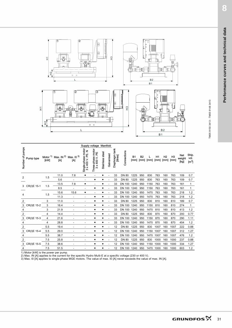
2
CR(I)E 15-1
1.511.0 7.8 ● - ● - 33 DN 80 1225 950 830 763 160 763 109 0.75.6 - - ● ● - 33 DN 80 1225 950 830 763 160 763 109 0.7
3 1.513.5 7.8 ● - ● - 33 DN 100 1240 950 1150 763 160 763 161 18.5 - - ● ● - 33 DN 100 1240 950 1150 763 160 763 161 1
4 1.515.6 15.6 ● - ● - 33 DN 100 1240 950 1470 763 160 763 218 1.211.3 - - ● ● - 33 DN 100 1240 950 1470 763 160 763 218 1.2
2CR(I)E 15-2
3 11.0 - - ● ● - 33 DN 80 1225 950 830 810 160 810 189 0.73 3 16.4 - - ● ● - 33 DN 100 1240 950 1150 810 160 810 274 14 3 21.9 - - ● ● - 33 DN 100 1240 950 1470 810 160 810 413 1.22
CR(I)E 15-34 14.4 - - ● ● - 33 DN 80 1225 950 830 870 160 870 200 0.77
3 4 21.6 - - ● ● - 33 DN 100 1240 950 1150 870 160 870 290 1.114 4 28.8 - - ● ● - 33 DN 100 1240 950 1470 870 160 870 454 1.22
CR(I)E 15-45.5 19.4 - - ● ● - 12 DN 80 1225 950 830 1007 160 1007 222 0.88
3 5.5 29.0 - - ● ● - 12 DN 100 1240 950 1150 1007 160 1007 312 1.274 5.5 38.7 - - ● ● - 12 DN 100 1240 950 1470 1007 160 1007 476 1.22
CR(I)E 15-57.5 25.8 - - ● ● - 12 DN 80 1225 950 830 1000 160 1000 237 0.88
3 7.5 38.6 - - ● ● - 12 DN 100 1240 950 1150 1000 160 1000 334 1.274 7.5 51.5 - - ● ● - 12 DN 100 1240 950 1470 1000 160 1000 603 1.2
31
Pe
rform
an
ce
cu
rve
s a
nd
tec
hn
ica
l da
ta
32
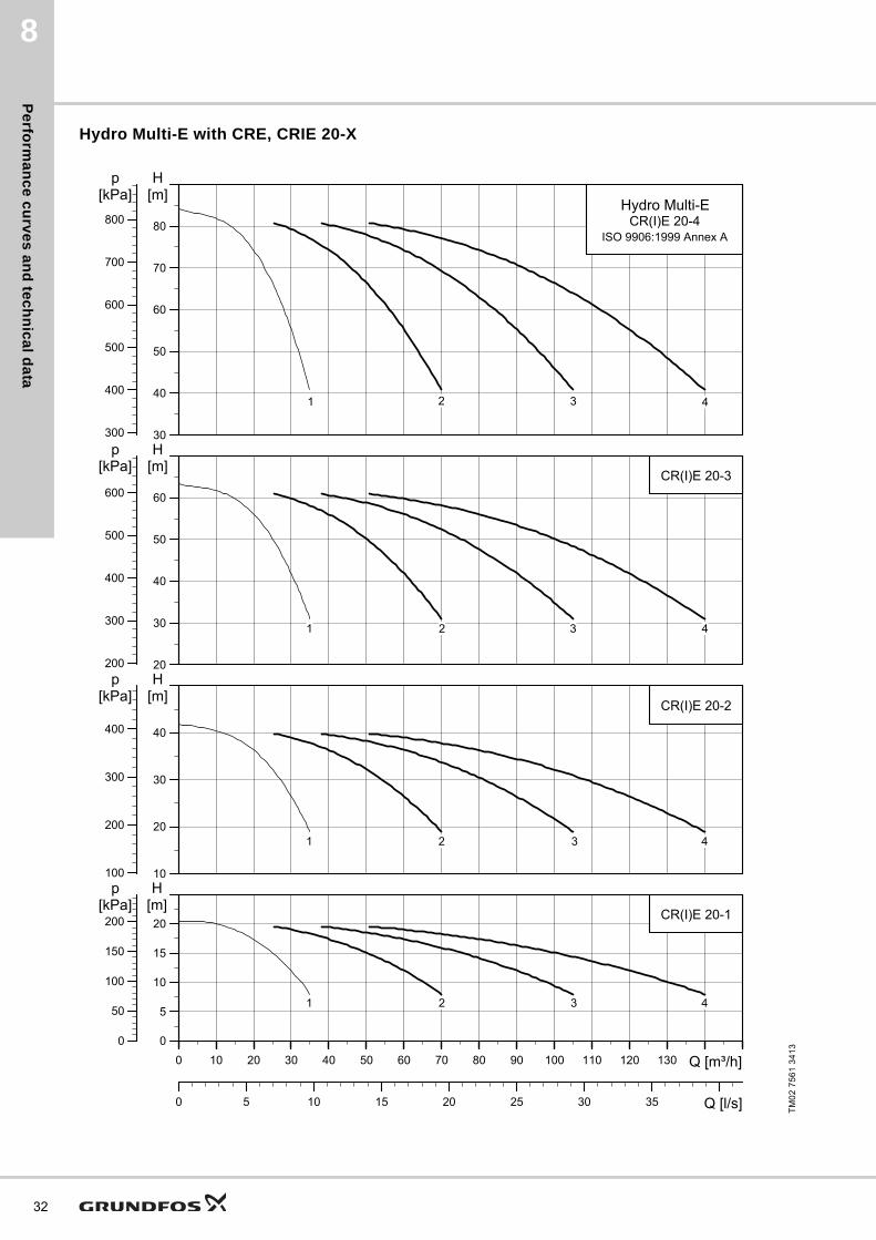
8
Hydro Multi-E with CRE, CRIE 20-X
TM
02
75
61
34
13
0 10 20 30 40 50 60 70 80 90 100 110 120 130 Q [m³/h]
0
5
10
15
20
H[m]
0 5 10 15 20 25 30 35 Q [l/s]
0
50
100
150
200
p[kPa]
CR(I)E 20-1
4321
0 10 20 30 40 50 60 70 80 90 100 110 120 130 Q [m³/h]
10
20
30
40
H[m]
100
200
300
400
p[kPa]
CR(I)E 20-2
4321
0 10 20 30 40 50 60 70 80 90 100 110 120 130 Q [m³/h]
20
30
40
50
60
H[m]
200
300
400
500
600
p[kPa]
CR(I)E 20-3
4321
0 10 20 30 40 50 60 70 80 90 100 110 120 130 Q [m³/h]
30
40
50
60
70
80
H[m]
300
400
500
600
700
800
p[kPa]
Hydro Multi-ECR(I)E 20-4
ISO 9906:1999 Annex A
4321
Pe
rfo
rma
nc
e c
urv
es
an
d t
ec
hn
ica
l d
ata
8
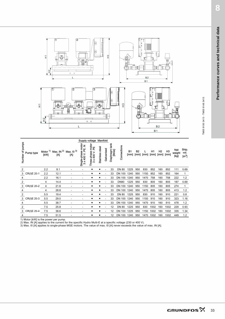
1) Motor [kW] is the power per pump.2) Max. IN [A] applies to the current for the specific Hydro Multi-E at a specific voltage (230 or 400 V).3) Max. I0 [A] applies to single-phase MGE motors. The value of max. I0 [A] never exceeds the value of max. IN [A].
TM
05
91
50
34
13
- T
M0
5 9
14
8 3
41
3
Num
ber o
f pum
ps
Pump type Motor 1)
[kW]Max. IN 2)
[A]Max. I0 3)
[A]
Supply voltage Manifold
Dia
phra
gm ta
nk[li
tres]
Con
nect
ions
B1[mm]
B2[mm]
L[mm]
H1[mm]
H2[mm]
H3[mm]
Netweight
[kg]
Ship.vol.[m3]
Sing
le-p
hase
mot
or3
x 40
0 V.
PE.
N
Thre
e-ph
ase
mot
or3
x 40
0 V.
PE
Stai
nles
s st
eel
Gal
vani
sed
2CR(I)E 20-1
2.2 8.1 - - ● ● - 33 DN 80 1225 950 830 852 160 852 111 0.693 2.2 12.1 - - ● ● - 33 DN 100 1240 950 1150 852 160 852 164 14 2.2 16.1 - - ● ● - 33 DN 100 1240 950 1470 758 160 758 222 1.22
CR(I)E 20-24 14.4 - - ● ● - 33 DN80 1225 950 830 805 160 805 187 0.69
3 4 21.6 - - ● ● - 33 DN 100 1240 950 1150 805 160 805 274 14 4 28.8 - - ● ● - 33 DN 100 1240 950 1470 805 160 805 413 1.22
CR(I)E 20-35.5 19.4 - - ● ● - 33 DN 80 1225 950 830 910 160 910 221 0.8
3 5.5 29.0 - - ● ● - 33 DN 100 1240 950 1150 910 160 910 323 1.164 5.5 38.7 - - ● ● - 33 DN 100 1240 950 1470 910 160 910 478 1.22
CR(I)E 20-47.5 25.8 - - ● ● - 12 DN 80 1225 950 830 1002 160 1002 229 0.93
3 7.5 38.6 - - ● ● - 12 DN 100 1225 950 1150 1002 160 1002 335 1.344 7.5 51.5 - - ● ● - 12 DN 100 1240 950 1470 1002 160 1002 449 1.2
2 31
21
33
Pe
rform
an
ce
cu
rve
s a
nd
tec
hn
ica
l da
ta
34
8
Hydro Multi-E with CME 3-5
TM
05
22
97
34
13
0 2 4 6 8 10 12 14 16 Q [m³/h]
20
30
40
50
60
70
H[m]
200
300
400
500
600
700
p[kPa]
CME 3-5
1 2 3
0 2 4 6 8 10 12 14 16 Q [m³/h]
20
40
60
80
100
[m]H
200
400
600
800
1000
[kPa]p
CME 3-7
1 2 3
0 2 4 6 8 10 12 14 16 Q [m³/h]
0
10
20
30
40
[m]H
0
100
200
300
400
[kPa]p
0 1 2 3 4 Q [l/s]
CME 3-3
1 2 3
0 2 4 6 8 10 12 14 16 Q [m³/h]
40
60
80
100
120
[m]H
400
600
800
1000
1200
[kPa]p
Hydro Multi-ECME 3-9
ISO 9906:1999 Annex A
1 2 3
CME-ACME-I
Pe
rfo
rma
nc
e c
urv
es
an
d t
ec
hn
ica
l d
ata
8
TM
03
09
24
08
05
- T
M0
3 0
92
3 0
80
5
Num
ber o
f pum
ps
Pump type Motor 1)
[kW]Max. IN 2)
[A]Max. I0 3)
[A]
Supply voltage Manifold
Dia
phra
gm ta
nk[li
tres]
Con
nect
ions
B1[mm]
B2[mm]
L[mm]
H1[mm]
H2[mm]
H3[mm]
Netweight
[kg]
Ship.vol.[m3]
Sing
le-p
hase
mot
or3
x 40
0 V.
PE.
N
Thre
e-ph
ase
mot
or3
x 40
0 V.
PE
Stai
nles
s st
eel
Gal
vani
sed
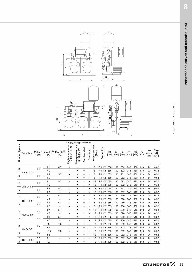
2CME-I 3-3
1.18.1 5.7 ● - ● - 8 R 1 1/2 585 190 592 345 530 910 72 0.324.2 - - ● ● - 8 R 1 1/2 585 190 592 345 530 910 72 0.32
3 1.19.9 5.7 ● - ● - 8 R 1 1/2 585 190 962 345 530 910 88 0.526.3 - - ● ● - 8 R 1 1/2 585 190 962 345 530 910 88 0.52
2CME-A 3-3
1.18.1 5.7 - ● - ● 12 R 1 1/2 585 190 592 345 510 890 74 0.324.2 - - ● - ● 12 R 1 1/2 585 190 592 345 510 890 74 0.32
3 1.19.9 5.7 - ● - ● 12 R 1 1/2 585 190 962 345 510 890 90 0.526.3 - - ● - ● 12 R 1 1/2 585 190 962 345 510 890 90 0.52
2CME-I 3-5
1.18.1 5.7 - ● ● - 8 R 1 1/2 585 190 590 345 530 910 74 0.324.2 - - ● ● - 8 R 1 1/2 585 190 590 345 530 910 74 0.32
3 1.19.9 5.7 - ● ● - 8 R 1 1/2 585 190 960 345 530 910 90 0.526.3 - - ● ● - 8 R 1 1/2 585 190 960 345 530 910 90 0.52
2CME-A 3-5
1.18.1 5.7 - ● - ● 12 R 1 1/2 585 190 590 345 510 890 76 0.324.2 - - ● - ● 12 R 1 1/2 585 190 590 345 510 890 76 0.32
3 1.19.9 5.7 - ● - ● 12 R 1 1/2 585 190 960 345 510 890 92 0.526.3 - - ● - ● 12 R 1 1/2 585 190 960 345 510 890 92 0.52
2CME-I 3-7
1.511.1 7.8 - ● ● - 12 R 1 1/2 585 190 592 345 510 890 75 0.325.6 - - ● ● - 12 R 1 1/2 585 190 592 345 510 890 75 0.32
3 1.513.5 7.8 - ● ● - 12 R 1 1/2 585 190 962 345 510 890 90 0.528.5 - - ● ● - 12 R 1 1/2 585 190 962 345 510 890 90 0.52
2CME-I 3-9
2.2 8.1 - - ● ● - 12 R 1 1/2 585 190 592 345 510 890 75 0.323 2.2 12.1 - - ● ● - 12 R 1 1/2 585 190 592 345 510 890 91 0.52
35
Pe
rform
an
ce
cu
rve
s a
nd
tec
hn
ica
l da
ta
36
8
Hydro Multi-E with CME 5-X
TM
05
22
98
34
13
0 2 4 6 8 10 12 14 16 18 20 22 Q [m³/h]
40
50
60
70
80
H[m]
400
500
600
700
800
p[kPa]
CME 5-6
1 2 3
0 2 4 6 8 10 12 14 16 18 20 22 Q [m³/h]
60
70
80
90
100
110[m]H
600
700
800
900
1000
[kPa]p
CME 5-8Hydro Multi-E
ISO 9906:1999 Annex A
1 2 3
CME-A
CME-I
0 2 4 6 8 10 12 14 16 18 20 22 Q [m³/h]
10
20
30
40
[m]H
100
200
300
400
[kPa]p
0 1 2 3 4 5 6 Q [l/s]
CME 5-3
1 2 3
0 2 4 6 8 10 12 14 16 18 20 22 Q [m³/h]
20
30
40
50
60
[m]H
200
300
400
500
600
[kPa]p
CME 5-4
1 2 3
0 2 4 6 8 10 12 14 16 18 20 22 Q [m³/h]
30
40
50
60
70
[m]H
300
400
500
600
700[kPa]
p
CME 5-5
1 2 3
Pe
rfo
rma
nc
e c
urv
es
an
d t
ec
hn
ica
l d
ata
8
TM
03
09
24
08
05
- T
M0
3 0
92
3 0
80
5
Num
ber o
f pum
ps
Pump type Motor 1)
[kW]Max. IN 2)
[A]Max. I0 3)
[A]
Supply voltage Manifold
Dia
phra
gm ta
nk[li
tres]
Con
nect
ions
B1[mm]
B2[mm]
L[mm]
H1[mm]
H2[mm]
H3[mm]
Netweight
[kg]
Ship.vol.[m3]
Sing
le-p
hase
mot
or3
x 40
0 V.
PE.
N
Thre
e-ph
ase
mot
or3
x 40
0 V.
PE
Stai
nles
s st
eel
Gal
vani
sed
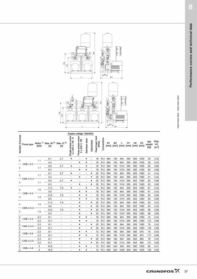
2CME-I 5-3
1.18.1 5.7 ● - ● - 18 R 2 584 150 644 390 585 1055 39 0.424.2 - - ● ● - 18 R 2 584 150 644 390 585 1055 39 0.42
3 1.19.9 5.7 ● - ● - 18 R 2 584 150 1014 390 585 1055 60 0.666.3 - - ● ● - 18 R 2 584 150 1014 390 585 1055 60 0.66
2CME-A 5-3
1.18.1 5.7 ● - - ● 25 R 2 584 150 644 390 605 1080 41 0.424.2 - - ● - ● 25 R 2 584 150 644 390 605 1080 41 0.42
3 1.19.9 5.7 ● - - ● 25 R 2 584 150 1014 390 605 1080 63 0.666.3 - - ● - ● 25 R 2 584 150 1014 390 605 1080 63 0.66
2CME-I 5-4
1.511.0 7.8 ● - ● - 18 R 2 584 150 644 390 605 1060 61 0.425.6 - - ● ● - 18 R 2 584 150 644 390 605 1060 61 0.42
3 1.513.5 7.8 - ● ● - 18 R 2 584 150 1014 390 605 1060 93 0.668.5 - - ● ● - 18 R 2 584 150 1014 390 625 1080 93 0.66
2CME-A 5-4
1.511.0 7.8 - ● - ● 25 R 2 584 150 644 390 605 1080 63 0.425.6 - - ● - ● 25 R 2 584 150 644 390 605 1080 63 0.42
3 1.513.5 7.8 - ● - ● 25 R 2 584 150 1014 390 605 1080 96 0.668.5 - - ● - ● 25 R 2 584 150 1014 390 605 1080 96 0.66
2CME-I 5-5
2.2 8.1 - - ● ● - 18 R 2 584 185 644 390 585 1080 74 0.423 2.2 12.1 - - ● ● - 18 R 2 584 185 1014 390 585 1080 112 0.662
CME-A 5-52.2 8.1 - - ● - ● 25 R 2 584 185 644 390 605 1080 76 0.42
3 2.2 12.1 - - ● - ● 25 R 2 584 185 1014 390 605 1080 118 0.662
CME-I 5-62.2 8.1 - - ● ● - 12 R 2 584 180 644 390 585 975 75 0.42
3 2.2 12.1 - - ● ● - 12 R 2 584 180 1014 390 585 975 117 0.662
CME-A 5-62.2 8.1 - - ● - ● 25 R 2 584 180 644 390 605 995 76 0.42
3 2.2 12.1 - - ● - ● 25 R 2 584 180 1014 390 605 995 121 0.662
CME-I 5-83 10.6 - - ● ● - 12 R 2 650 220 635 400 590 1005 95 0.41
3 3 15.9 - - ● ● - 12 R 2 650 220 1005 400 590 1005 136 0.65
37
Pe
rform
an
ce
cu
rve
s a
nd
tec
hn
ica
l da
ta
38
8
Hydro Multi-E with CME 10-X
TM
05
22
99
34
13
0 5 10 15 20 25 30 35 40 45 50 Q [m³/h]
10
20
30
40
50
[m]H
100
200
300
400
500
[kPa]p
CME 10-5Hydro Multi-E
ISO 9906:1999 Annex A
1 2 3
CME-ACME-I
0 5 10 15 20 25 30 35 40 45 50 Q [m³/h]
10
20
30
40
50
[m]H
100
200
300
400
500
[kPa]p
0 2 4 6 8 10 12 14 Q [l/s]
CME 10-2
1 2 3
0 5 10 15 20 25 30 35 40 45 50 Q [m³/h]
20
30
40
50
60
70
[m]H
200
300
400
500
600
700[kPa]
p
CME 10-3
1 2 3
0 5 10 15 20 25 30 35 40 45 50 Q [m³/h]
40
50
60
70
80
90
[m]H
400
500
600
700
800
900[kPa]
p
CME 10-4
1 2 3

Pe
rfo
rma
nc
e c
urv
es
an
d t
ec
hn
ica
l d
ata
8
TM
03
09
24
08
05
- T
M0
3 0
92
3 0
80
5
Num
ber o
f pum
ps
Pump type Motor 1)
[kW]Max. IN 2)
[A]Max. I0 3)
[A]
Supply voltage Manifold
Dia
phra
gm ta
nk[li
tres]
Con
nect
ions
B1[mm]
B2[mm]
L[mm]
H1[mm]
H2[mm]
H3[mm]
Netweight
[kg]
Ship.vol.[m3]
Sing
le-p
hase
mot
or3
x 40
0 V.
PE.
N
Thre
e-ph
ase
mot
or3
x 40
0 V.
PE
Stai
nles
s st
eel
Gal
vani
sed
2CME-I 10-2
2.2 8.1 - - ● ● - 25 R 2 1/2 544 150 644 465 610 1205 69 0.473 2.2 12.1 - - ● ● - 25 R 2 1/2 544 150 1009 465 610 1205 104 0.742
CME-A 10-22.2 8.1 - - ● - ● 25 R 2 1/2 544 150 644 465 635 1230 101 0.47
3 2.2 12.1 - - ● - ● 25 R 2 1/2 544 150 1009 465 635 1230 150 0.742
CME-I 10-34 13.2 - - ● ● - 25 R 2 1/2 665 180 664 475 590 1190 121 0.54
3 4 19.8 - - ● ● - 25 R 2 1/2 665 180 1034 475 590 1190 174 0.822
CME-A 10-34 13.2 - - ● - ● 25 R 2 1/2 670 160 664 475 620 1220 125 0.54
3 4 19.8 - - ● - ● 25 R 2 1/2 670 160 1034 475 620 1220 180 0.822
CME-I 10-44 19.6 - - ● ● - 12 R 2 1/2 674 180 664 475 590 1220 122 0.53
3 4 29.4 - - ● ● - 12 R 2 1/2 674 180 1034 475 620 1220 175 0.852
CME-I 10-54 19.6 - - ● ● - 12 R 2 1/2 665 160 660 475 620 1220 123 0.54
3 4 29.4 - - ● ● - 12 R 2 1/2 670 180 1030 475 620 1220 230 0.85
39
Pe
rform
an
ce
cu
rve
s a
nd
tec
hn
ica
l da
ta
40
8
Hydro Multi-E with CME 15-X
TM
05
23
00
34
13
0 10 20 30 40 50 60 70 80 Q [m³/h]
40
45
50
55
60
65
70
75
[m]H
400
450
500
550
600
650
700
[kPa]p
CME 15-3Hydro Multi-E
ISO 9906:1999 Annex A
1 2 3
CME-ACME-I
0 10 20 30 40 50 60 70 80 Q [m³/h]
24
28
32
36
40
44
48
52
[m]H
250
300
350
400
450
500
[kPa]p
CME 15-2
1 2 3
0 10 20 30 40 50 60 70 80 Q [m³/h]
8
12
16
20
24
28
[m]H
100
150
200
250
[kPa]p
CME 15-1
1 2 3
Pe
rfo
rma
nc
e c
urv
es
an
d t
ec
hn
ica
l d
ata
8
TM
03
09
24
08
05
- T
M0
3 0
92
3 0
80
5
Num
ber o
f pum
ps
Pump type Motor 1)
[kW]Max. IN 2)
[A]Max. I0 3)
[A]
Supply voltage Manifold
Dia
phra
gm ta
nk[li
tres]
Con
nect
ions
B1[mm]
B2[mm]
L[mm]
H1[mm]
H2[mm]
H3[mm]
Netweight
[kg]
Ship.vol.[m3]
Sing
le-p
hase
mot
or3
x 40
0 V.
PE.
N
Thre
e-ph
ase
mot
or3
x 40
0 V.
PE
Stai
nles
s st
eel
Gal
vani
sed
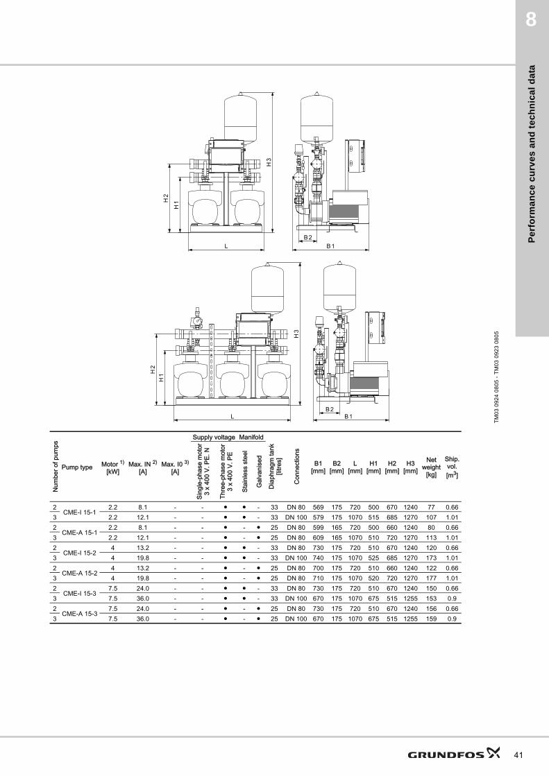
2CME-I 15-1
2.2 8.1 - - ● ● - 33 DN 80 569 175 720 500 670 1240 77 0.663 2.2 12.1 - - ● ● - 33 DN 100 579 175 1070 515 685 1270 107 1.012
CME-A 15-12.2 8.1 - - ● - ● 25 DN 80 599 165 720 500 660 1240 80 0.66
3 2.2 12.1 - - ● - ● 25 DN 80 609 165 1070 510 720 1270 113 1.012
CME-I 15-24 13.2 - - ● ● - 33 DN 80 730 175 720 510 670 1240 120 0.66
3 4 19.8 - - ● ● - 33 DN 100 740 175 1070 525 685 1270 173 1.012
CME-A 15-24 13.2 - - ● - ● 25 DN 80 700 175 720 510 660 1240 122 0.66
3 4 19.8 - - ● - ● 25 DN 80 710 175 1070 520 720 1270 177 1.012
CME-I 15-37.5 24.0 - - ● ● - 33 DN 80 730 175 720 510 670 1240 150 0.66
3 7.5 36.0 - - ● ● - 33 DN 100 670 175 1070 675 515 1255 153 0.92
CME-A 15-37.5 24.0 - - ● - ● 25 DN 80 730 175 720 510 670 1240 156 0.66
3 7.5 36.0 - - ● - ● 25 DN 100 670 175 1070 675 515 1255 159 0.9
41
Op
tion
al e
qu
ipm
en
t
42
Hydro Multi-E9
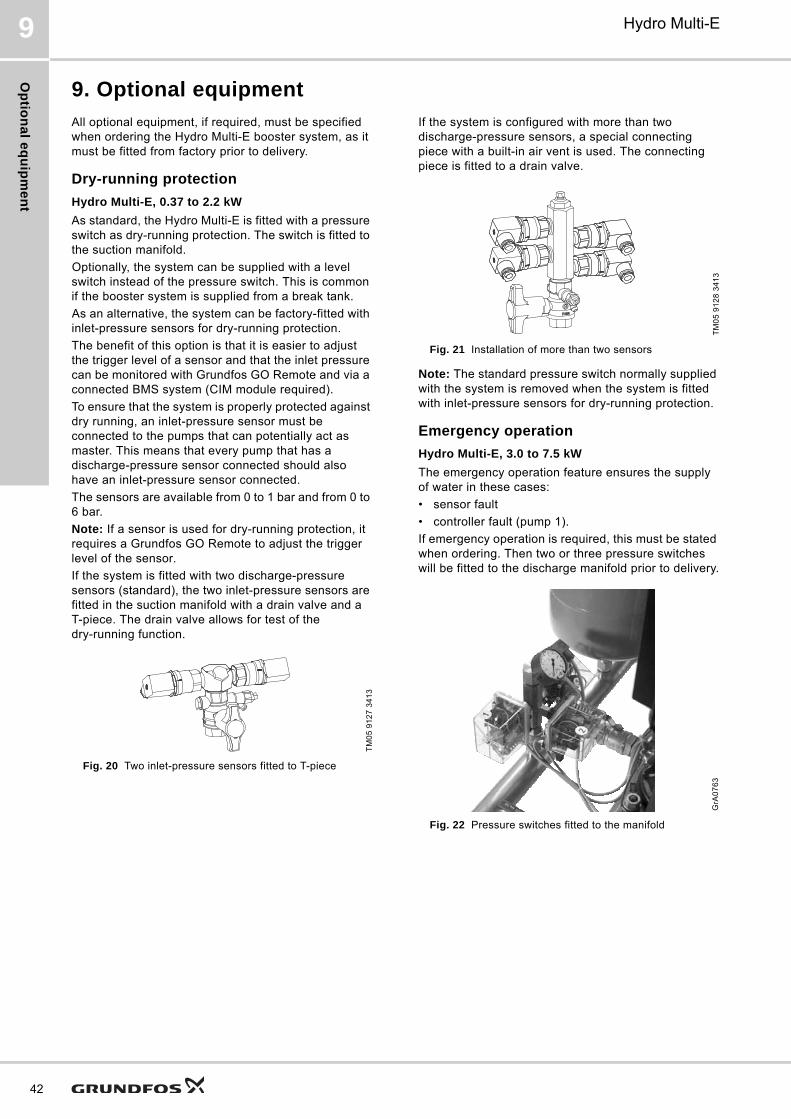
9. Optional equipment
All optional equipment, if required, must be specified when ordering the Hydro Multi-E booster system, as it must be fitted from factory prior to delivery.
Dry-running protection
Hydro Multi-E, 0.37 to 2.2 kW
As standard, the Hydro Multi-E is fitted with a pressure switch as dry-running protection. The switch is fitted to the suction manifold.
Optionally, the system can be supplied with a level switch instead of the pressure switch. This is common if the booster system is supplied from a break tank.
As an alternative, the system can be factory-fitted with inlet-pressure sensors for dry-running protection.
The benefit of this option is that it is easier to adjust the trigger level of a sensor and that the inlet pressure can be monitored with Grundfos GO Remote and via a connected BMS system (CIM module required).
To ensure that the system is properly protected against dry running, an inlet-pressure sensor must be connected to the pumps that can potentially act as master. This means that every pump that has a discharge-pressure sensor connected should also have an inlet-pressure sensor connected.
The sensors are available from 0 to 1 bar and from 0 to 6 bar.
Note: If a sensor is used for dry-running protection, it requires a Grundfos GO Remote to adjust the trigger level of the sensor.
If the system is fitted with two discharge-pressure sensors (standard), the two inlet-pressure sensors are fitted in the suction manifold with a drain valve and a T-piece. The drain valve allows for test of the dry-running function.
Fig. 20 Two inlet-pressure sensors fitted to T-piece
If the system is configured with more than two discharge-pressure sensors, a special connecting piece with a built-in air vent is used. The connecting piece is fitted to a drain valve.
Fig. 21 Installation of more than two sensors
Note: The standard pressure switch normally supplied with the system is removed when the system is fitted with inlet-pressure sensors for dry-running protection.
Emergency operation
Hydro Multi-E, 3.0 to 7.5 kW
The emergency operation feature ensures the supply of water in these cases:
• sensor fault
• controller fault (pump 1).
If emergency operation is required, this must be stated when ordering. Then two or three pressure switches will be fitted to the discharge manifold prior to delivery.
Fig. 22 Pressure switches fitted to the manifold
TM
05
91
27
34
13
TM
05
91
28
34
13
GrA
07
63
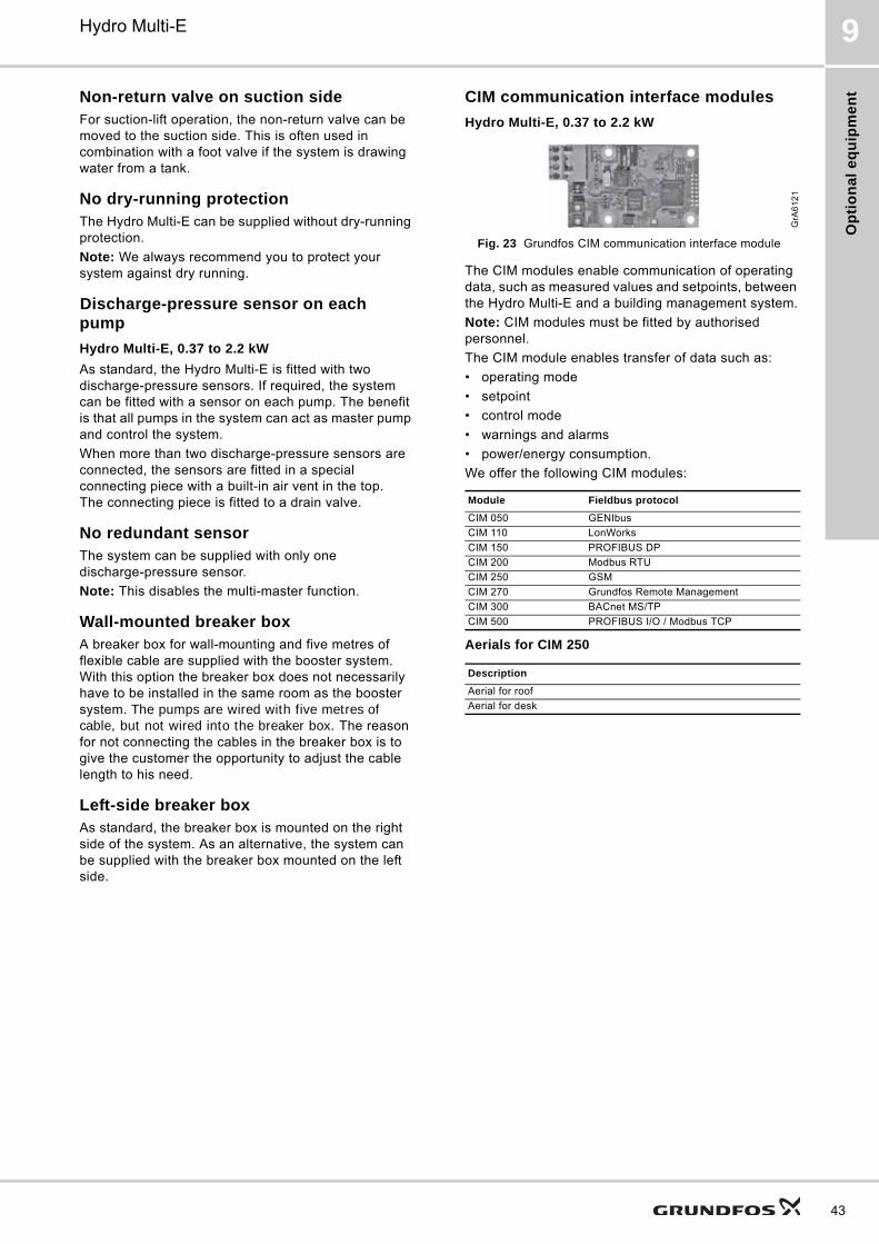
Op
tio
na
l e
qu
ipm
en
t
Hydro Multi-E 9
Non-return valve on suction sideFor suction-lift operation, the non-return valve can be moved to the suction side. This is often used in combination with a foot valve if the system is drawing water from a tank.
No dry-running protectionThe Hydro Multi-E can be supplied without dry-running protection.
Note: We always recommend you to protect your system against dry running.
Discharge-pressure sensor on each pump
Hydro Multi-E, 0.37 to 2.2 kW
As standard, the Hydro Multi-E is fitted with two discharge-pressure sensors. If required, the system can be fitted with a sensor on each pump. The benefit is that all pumps in the system can act as master pump and control the system.
When more than two discharge-pressure sensors are connected, the sensors are fitted in a special connecting piece with a built-in air vent in the top. The connecting piece is fitted to a drain valve.
No redundant sensorThe system can be supplied with only one discharge-pressure sensor.
Note: This disables the multi-master function.
Wall-mounted breaker boxA breaker box for wall-mounting and five metres of flexible cable are supplied with the booster system. With this option the breaker box does not necessarily have to be installed in the same room as the booster system. The pumps are wired with five metres of cable, but not wired into the breaker box. The reason for not connecting the cables in the breaker box is to give the customer the opportunity to adjust the cable length to his need.
Left-side breaker boxAs standard, the breaker box is mounted on the right side of the system. As an alternative, the system can be supplied with the breaker box mounted on the left side.
CIM communication interface modules
Hydro Multi-E, 0.37 to 2.2 kW
Fig. 23 Grundfos CIM communication interface module
The CIM modules enable communication of operating data, such as measured values and setpoints, between the Hydro Multi-E and a building management system.
Note: CIM modules must be fitted by authorised personnel.
The CIM module enables transfer of data such as:
• operating mode
• setpoint
• control mode
• warnings and alarms
• power/energy consumption.
We offer the following CIM modules:
Aerials for CIM 250
GrA
61
21
Module Fieldbus protocol
CIM 050 GENIbus
CIM 110 LonWorks
CIM 150 PROFIBUS DP
CIM 200 Modbus RTU
CIM 250 GSM
CIM 270 Grundfos Remote Management
CIM 300 BACnet MS/TP
CIM 500 PROFIBUS I/O / Modbus TCP
Description
Aerial for roof
Aerial for desk
43

Ac
ce
ss
orie
s
44
Hydro Multi-E10
10. Accessories
Grundfos GO RemoteThe Grundfos GO Remote is used for wireless infrared or radio communication with the pumps.
Various Grundfos GO Remote variants are available. The variants are described in the following.
MI 201
The MI 201 is a complete solution, consisting of an Apple iPod touch 4G and a Grundfos cover for infrared and radio communication with Grundfos pumps or systems.
Fig. 24 MI 201
Supplied with the product:
• Apple iPod touch 4G incl. accessories
• Grundfos MI 201 cover
• battery charger
• quick guide.
MI 202 and MI 204The MI 202 and MI 204 are add-on modules with built-in infrared and radio communication.
• The MI 202 is used in conjunction with Apple iPod Touch 4G, iPhone 4 or IPhone 4S
• The MI 204 is used in conjunction with Apple iPod Touch 5G, iPhone 5 or later.
Fig. 25 MI 202 and MI 204
MI 301The MI 301 is a module with built-in infrared and radio communication. The MI 301 must be used in conjunction with an Android or iOS-based Smartphone with a Bluetooth connection. The MI 301 has rechargeable Li-ion battery and must be charged separately.
Fig. 26 MI 301
Supplied with the product:
• battery charger
• quick guide.
TM
05
38
86
17
12
TM
05
38
87
- T
M0
5 7
70
4
TM
05
38
90
17
12
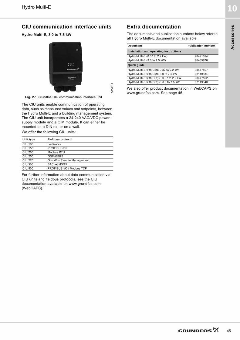
Ac
ce
ss
ori
es
Hydro Multi-E 10
CIU communication interface units
Hydro Multi-E, 3.0 to 7.5 kW
Fig. 27 Grundfos CIU communication interface unit
The CIU units enable communication of operating data, such as measured values and setpoints, between the Hydro Multi-E and a building management system. The CIU unit incorporates a 24-240 VAC/VDC power supply module and a CIM module. It can either be mounted on a DIN rail or on a wall.
We offer the following CIU units:
For further information about data communication via CIU units and fieldbus protocols, see the CIU documentation available on www.grundfos.com (WebCAPS).
Extra documentationThe documents and publication numbers below refer to all Hydro Multi-E documentation available.
We also offer product documentation in WebCAPS on www.grundfos.com. See page 46.G
rA6
118
Unit type Fieldbus protocol
CIU 100 LonWorks
CIU 150 PROFIBUS DP
CIU 200 Modbus RTU
CIU 250 GSM/GPRS
CIU 270 Grundfos Remote Management
CIU 300 BACnet MS/TP
CIU 500 PROFIBUS I/O / Modbus TCP
Document Publication number
Installation and operating instructions
Hydro Multi-E (0.37 to 2.2 kW) 98491894
Hydro Multi-E (3.0 to 7.5 kW) 96485976
Quick guide
Hydro Multi-E with CME 0.37 to 2.2 kW 98477597
Hydro Multi-E with CME 3.0 to 7.5 kW 98119834
Hydro Multi-E with CR(I)E 0.37 to 2.2 kW 98477592
Hydro Multi-E with CR(I)E 3.0 to 7.5 kW 97119840
45
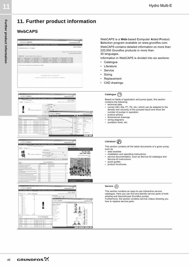
Fu
rthe
r pro
du
ct in
form
atio
n
46
Hydro Multi-E11
11. Further product information
WebCAPS
WebCAPS is a Web-based Computer Aided Product Selection program available on www.grundfos.com.
WebCAPS contains detailed information on more than 220,000 Grundfos products in more than 30 languages.
Information in WebCAPS is divided into six sections:
• Catalogue
• Literature
• Service
• Sizing
• Replacement
• CAD drawings.
Catalogue
Based on fields of application and pump types, this section contains the following:• technical data• curves (QH, Eta, P1, P2, etc.) which can be adapted to the
density and viscosity of the pumped liquid and show the number of pumps in operation
• product photos• dimensional drawings• wiring diagrams• quotation texts, etc.
Literature
This section contains all the latest documents of a given pump, such as• data booklets• installation and operating instructions• service documentation, such as Service kit catalogue and
Service kit instructions• quick guides• product brochures.
Service
This section contains an easy-to-use interactive service catalogue. Here you can find and identify service parts of both existing and discontinued Grundfos pumps.Furthermore, the section contains service videos showing you how to replace service parts.
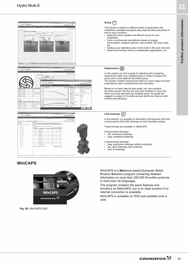
Fu
rth
er
pro
du
ct
info
rma
tio
n
Hydro Multi-E 11
WinCAPS
Fig. 28 WinCAPS DVD
Sizing
This section is based on different fields of application and installation examples and gives easy step-by-step instructions in how to size a product:• Select the most suitable and efficient pump for your
installation.• Carry out advanced calculations based on energy,
consumption, payback periods, load profiles, life cycle costs, etc.
• Analyse your selected pump via the built-in life cycle cost tool.• Determine the flow velocity in wastewater applications, etc.
Replacement
In this section you find a guide to selecting and comparing replacement data of an installed pump in order to replace the pump with a more efficient Grundfos pump. The section contains replacement data of a wide range of pumps produced by other manufacturers than Grundfos.
Based on an easy step-by-step guide, you can compare Grundfos pumps with the one you have installed on your site. When you have specified the installed pump, the guide will suggest a number of Grundfos pumps which can improve both comfort and efficiency.
CAD drawings
In this section, it is possible to download 2-dimensional (2D) and 3-dimensional (3D) CAD drawings of most Grundfos pumps.
These formats are available in WebCAPS:
2-dimensional drawings:• .dxf, wireframe drawings• .dwg, wireframe drawings.
3-dimensional drawings:• .dwg, wireframe drawings (without surfaces)• .stp, solid drawings (with surfaces)• .eprt, E-drawings.
WinCAPS is a Windows-based Computer Aided Product Selection program containing detailed information on more than 220,000 Grundfos products in more than 30 languages.
The program contains the same features and functions as WebCAPS, but is an ideal solution if no internet connection is available.
WinCAPS is available on DVD and updated once a year.
0 1
47

Fu
rthe
r pro
du
ct in
form
atio
n
48
Hydro Multi-E11
GO CAPS
Mobile solution for professionals on the GO!
CAPS functionality on the mobile workplace.
Subject to alterations.

49

50

51

GRUNDFOS A/S DK-8850 Bjerringbro . DenmarkTelephone: +45 87 50 14 00www.grundfos.com
96488673 0913
ECM: 1120844 Th
e n
am
e G
run
dfo
s, t
he
Gru
nd
fos
log
o,
an
d b
e t
hin
k i
nn
ov
ate
are
re
gis
tere
d t
rad
em
ark
s o
wn
ed
by
Gru
nd
fos
Ho
ldin
g A
/S o
r G
run
dfo
s A
/S,
De
nm
ark
. A
ll ri
gh
ts r
ese
rve
d w
orl
dw
ide
.©
Co
pyr
igh
t G
run
dfo
s H
old
ing
A/S