Embed Size (px)
Citation preview
HYDRO-LINE, INC.
HL SlidesTransfer and Lift Systems
RO
CKFORD, IL
Delivering Engineered Solutionsin Actuation Worldwide
REV. 4/00 10,000 CG
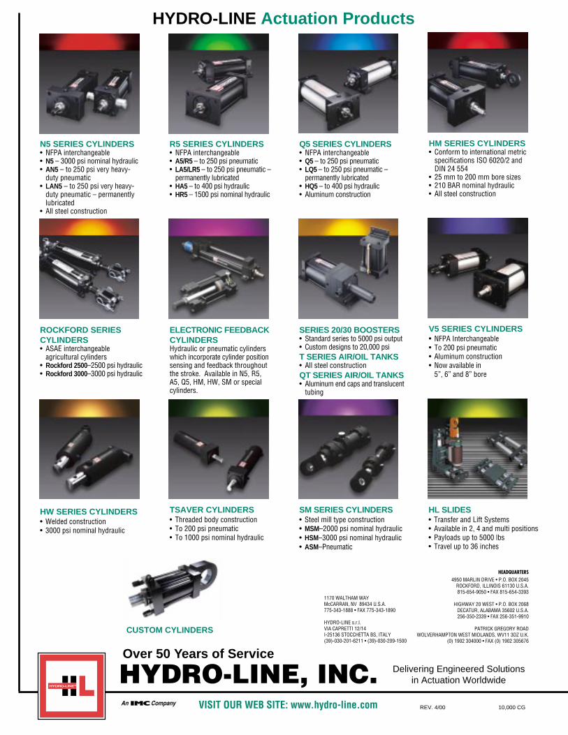
HYDRO-LINE Actuation Products
HM SERIES CYLINDERS• Conform to international metric
specifications ISO 6020/2 andDIN 24 554
• 25 mm to 200 mm bore sizes• 210 BAR nominal hydraulic• All steel construction
ROCKFORD SERIESCYLINDERS• ASAE interchangeable
agricultural cylinders• Rockford 2500–2500 psi hydraulic• Rockford 3000–3000 psi hydraulic
ELECTRONIC FEEDBACKCYLINDERSHydraulic or pneumatic cylinderswhich incorporate cylinder positionsensing and feedback throughoutthe stroke. Available in N5, R5,A5, Q5, HM, HW, SM or specialcylinders.
SERIES 20/30 BOOSTERS• Standard series to 5000 psi output• Custom designs to 20,000 psi T SERIES AIR/OIL TANKS• All steel constructionQT SERIES AIR/OIL TANKS• Aluminum end caps and translucent
tubing
N5 SERIES CYLINDERS• NFPA interchangeable• N5 – 3000 psi nominal hydraulic• AN5 – to 250 psi very heavy-
duty pneumatic• LAN5 – to 250 psi very heavy-
duty pneumatic – permanentlylubricated
• All steel construction
R5 SERIES CYLINDERS• NFPA interchangeable • A5/R5 – to 250 psi pneumatic• LA5/LR5 – to 250 psi pneumatic –
permanently lubricated• HA5 – to 400 psi hydraulic• HR5 – 1500 psi nominal hydraulic
Q5 SERIES CYLINDERS• NFPA interchangeable • Q5 – to 250 psi pneumatic• LQ5 – to 250 psi pneumatic –
permanently lubricated• HQ5 – to 400 psi hydraulic• Aluminum construction
CUSTOM CYLINDERS
V5 SERIES CYLINDERS• NFPA Interchangeable• To 200 psi pneumatic• Aluminum construction• Now available in
5”, 6” and 8” bore
HW SERIES CYLINDERS• Welded construction• 3000 psi nominal hydraulic
TSAVER CYLINDERS• Threaded body construction• To 200 psi pneumatic• To 1000 psi nominal hydraulic
SM SERIES CYLINDERS• Steel mill type construction• MSM–2000 psi nominal hydraulic• HSM–3000 psi nominal hydraulic• ASM–Pneumatic
HL SLIDES• Transfer and Lift Systems• Available in 2, 4 and multi positions• Payloads up to 5000 lbs• Travel up to 36 inches
1170 WALTHAM WAYMcCARRAN, NV 89434 U.S.A.775-343-1888 • FAX 775-343-1890
HYDRO-LINE s.r.l.VIA CAPRETTI 12/14I-25136 STOCCHETTA BS, ITALY(39)-030-201-6211 • (39)-030-209-1500
HEADQUARTERS4950 MARLIN DRIVE • P.O. BOX 2045
ROCKFORD, ILLINOIS 61130 U.S.A.815-654-9050 • FAX 815-654-3393
HIGHWAY 20 WEST • P.O. BOX 2068DECATUR, ALABAMA 35602 U.S.A.256-350-2339 • FAX 256-351-9910
PATRICK GREGORY ROADWOLVERHAMPTON WEST MIDLANDS, WV11 3DZ U.K.
(0) 1902 304000 • FAX (0) 1902 305676
VISIT OUR WEB SITE: www.hydro-line.com
Over 50 Years of Service

PATENTS PENDINGOR PATENTED52634025255591All Rights Reserved.

1
HL Series Slides
TABLE OF CONTENTS . . . . . . . . . . . . . . . . . . . . . . . . . . . . . . . . . . . . . . . . . . . . 1
PRODUCTS & SERVICES . . . . . . . . . . . . . . . . . . . . . . . . . . . . . . . . . . . . . . . . . . 2
APPLY IT, INSTALL IT, FORGET IT . . . . . . . . . . . . . . . . . . . . . . . . . . . . . . . . . . . . . 4
EBS/EBSM SERIES 2-POSITION SLIDES . . . . . . . . . . . . . . . . . . . . . . . . . . . . . . . . 6
EIS SERIES 4-POSITION SLIDES . . . . . . . . . . . . . . . . . . . . . . . . . . . . . . . . . . . . . 15
S SERIES 2-POSITION SLIDES . . . . . . . . . . . . . . . . . . . . . . . . . . . . . . . . . . . . . . 22
REPLACEMENT PARTS . . . . . . . . . . . . . . . . . . . . . . . . . . . . . . . . . . . . . . . . . . 29
APPLICATION APPROVAL FORM . . . . . . . . . . . . . . . . . . . . . . . . . . . . . . . . . . . . 34
Table of ContentsWe would like to take this opportunity to introduce Hydro-Line, Inc. to your company and the many benefits, which may be gainedby becoming a Hydro-Line customer.
Experience :
Hydro-Line, Inc. was established in 1946 and is committed to being a world leader in actuation. Hydro-Line provides industrial,agricultural and mobile markets with products of unparalleled quality and after-sale support. It is our mission to continuouslyimprove, so our partners remain ahead of their competition as we seek to stay ahead of ours.
Positioned for growth in a Global Market :
Hydro-Line is owned by International Motion Control and is part of the IMC Fluid Power Group. The goal of IMC is to be a worldleader in motion control and to build off the synergies of each company to develop state of the art technology. The IMC Fluid Groupis comprised of six manufacturing facilities strategically located throughout the world.
Market knowledge :
Hydro-Line’s success in markets such as automotive, plastic, foundry, oil & gas, agricultural, wood products and amusementmachinery comes through knowledge of our customer’s market. We speak the same language! However, knowledge alone is notenough, we earn the loyalty of customers through concurrent engineering, cost containment programs, mutual forecasting pro-grams, and internal program managers, who supervise accounts on a daily basis.
HL Slides are an extension of the high quality products we offer to companies throughout the world. We look forward to workingwith your company in the future.
Sincerely,Hydro-Line, Inc.
Thank you for using Hydro-Line...
2
HL Series Slides
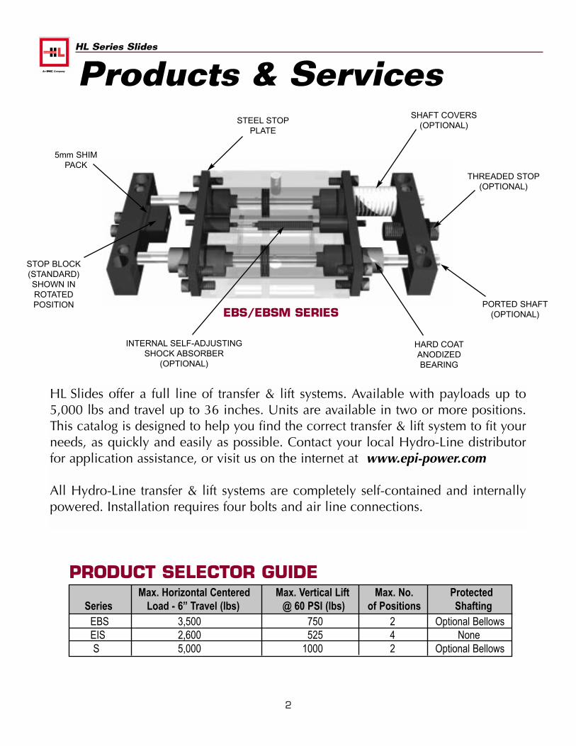
5mm SHIMPACK
STOP BLOCK(STANDARD)SHOWN INROTATEDPOSITION
THREADED STOP(OPTIONAL)
PORTED SHAFT(OPTIONAL)
HARD COATANODIZEDBEARING
SHAFT COVERS(OPTIONAL)
STEEL STOPPLATE
INTERNAL SELF-ADJUSTINGSHOCK ABSORBER
(OPTIONAL)
Max. Horizontal Centered Max. Vertical Lift Max. No. ProtectedSeries Load - 6” Travel (lbs) @ 60 PSI (lbs) of Positions Shafting
EBS 3,500 750 2 Optional BellowsEIS 2,600 525 4 NoneS 5,000 1000 2 Optional Bellows
PRODUCT SELECTOR GUIDE
EBS/EBSM SERIES
HL Slides offer a full line of transfer & lift systems. Available with payloads up to5,000 lbs and travel up to 36 inches. Units are available in two or more positions.This catalog is designed to help you find the correct transfer & lift system to fit yourneeds, as quickly and easily as possible. Contact your local Hydro-Line distributorfor application assistance, or visit us on the internet at www.epi-power.com
All Hydro-Line transfer & lift systems are completely self-contained and internallypowered. Installation requires four bolts and air line connections.
Products & Services
3
HL Series Slides
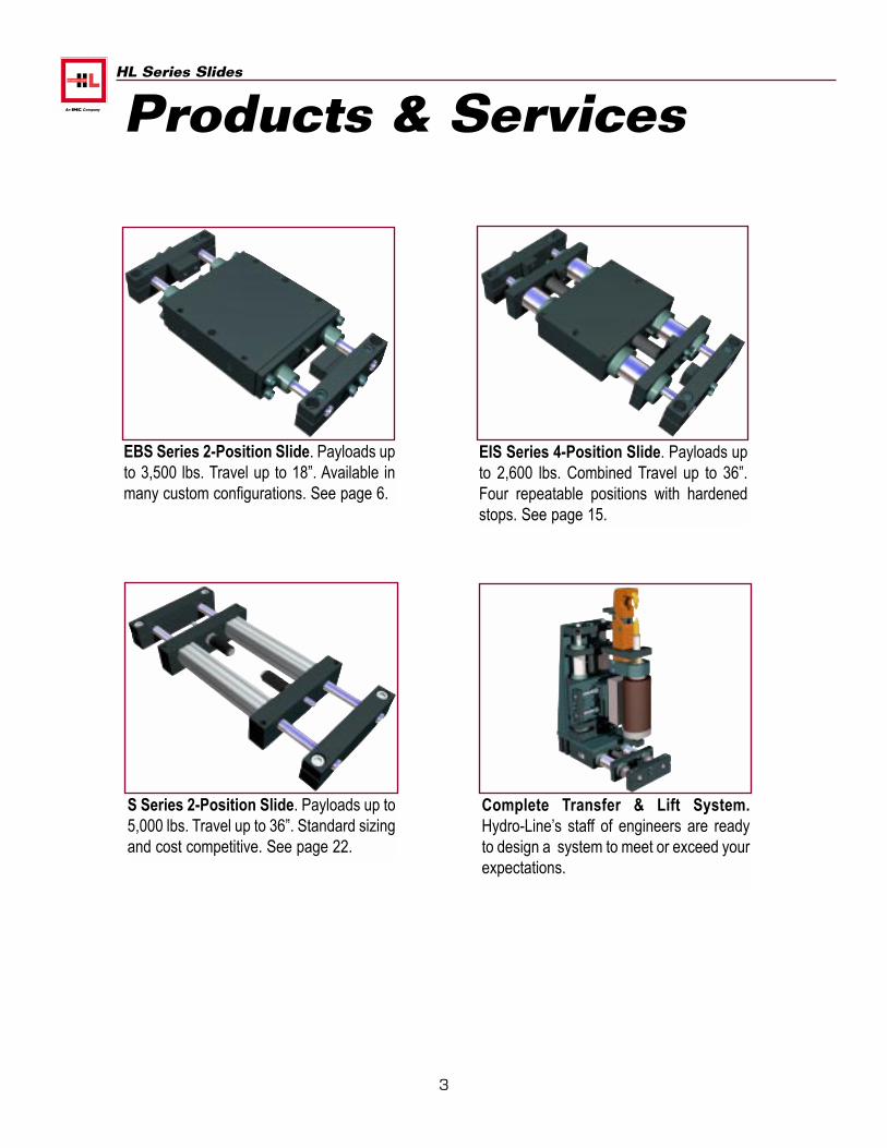
EBS Series 2-Position Slide. Payloads upto 3,500 lbs. Travel up to 18”. Available inmany custom configurations. See page 6.
S Series 2-Position Slide. Payloads up to5,000 lbs. Travel up to 36”. Standard sizingand cost competitive. See page 22.
EIS Series 4-Position Slide. Payloads upto 2,600 lbs. Combined Travel up to 36”.Four repeatable positions with hardenedstops. See page 15.
Products & Services
Complete Transfer & Lift System.Hydro-Line’s staff of engineers are readyto design a system to meet or exceed yourexpectations.
4
HL Series Slides
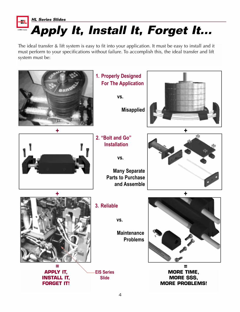
The ideal transfer & lift system is easy to fit into your application. It must be easy to install and itmust perform to your specifications without failure. To accomplish this, the ideal transfer and liftsystem must be:
1. Properly Designed For The Application
vs.
Misapplied
2. “Bolt and Go”Installation
vs.
Many SeparateParts to Purchase
and Assemble
3. Reliable
vs.
MaintenanceProblems
+
+
+
+
==APPLY IT,
INSTALL IT,FORGET IT!
MORE TIME,MORE $$$,
MORE PROBLEMS!
Apply It, Install It, Forget It...
EIS SeriesSlide
5
HL Series Slides
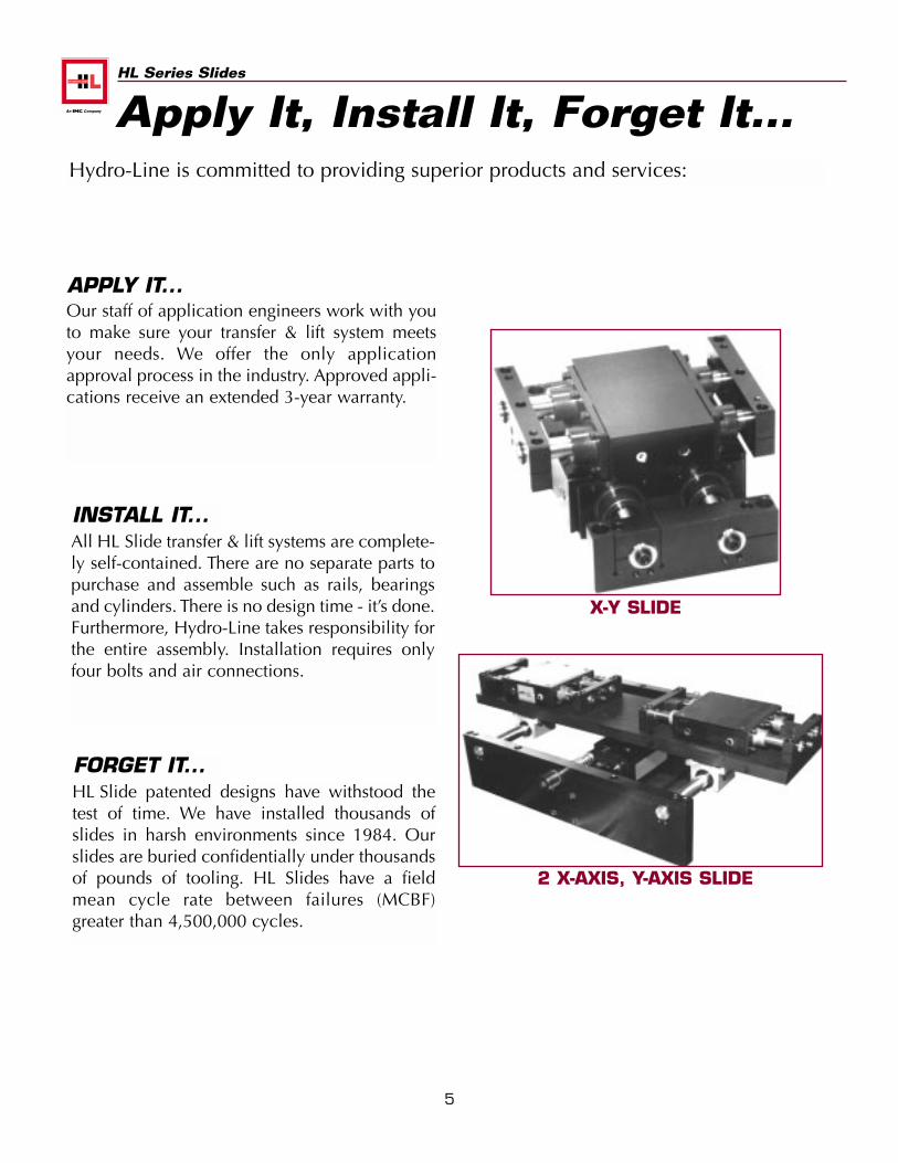
Hydro-Line is committed to providing superior products and services:
Our staff of application engineers work with youto make sure your transfer & lift system meetsyour needs. We offer the only applicationapproval process in the industry. Approved appli-cations receive an extended 3-year warranty.
APPLY IT...
All HL Slide transfer & lift systems are complete-ly self-contained. There are no separate parts topurchase and assemble such as rails, bearingsand cylinders. There is no design time - it’s done.Furthermore, Hydro-Line takes responsibility forthe entire assembly. Installation requires onlyfour bolts and air connections.
INSTALL IT...
HL Slide patented designs have withstood thetest of time. We have installed thousands ofslides in harsh environments since 1984. Ourslides are buried confidentially under thousandsof pounds of tooling. HL Slides have a fieldmean cycle rate between failures (MCBF)greater than 4,500,000 cycles.
FORGET IT...
X-Y SLIDE
Apply It, Install It, Forget It...
2 X-AXIS, Y-AXIS SLIDE
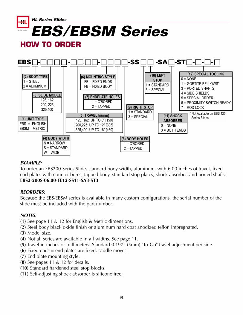
EXAMPLE:To order an EBS200 Series Slide, standard body width, aluminum, with 6.00 inches of travel, fixedend plates with counter bores, tapped body, standard stop plates, shock absorber, and ported shafts:EBS2-200S-06.00-FE12-SS11-SA3-ST3
REORDERS:Because the EBS/EBSM series is available in many custom configurations, the serial number of theslide must be included with the part number.
NOTES:(1) See page 11 & 12 for English & Metric dimensions.(2) Steel body black oxide finish or aluminum hard coat anodized teflon impregnated.(3) Model size.(4) Not all series are available in all widths. See page 11.(5) Travel in inches or millimeters. Standard 0.197” (5mm) “To-Go” travel adjustment per side.(6) Fixed ends = end plates are fixed, saddle moves.(7) End plate mounting style.(8) See pages 11 & 12 for details.(10) Standard hardened steel stop blocks. (11) Self-adjusting shock absorber is silicone free.
6
HL Series Slides
(2) BODY TYPE1 = STEEL2 = ALUMINUM
(4) BODY WIDTHN = NARROWS = STANDARDW = WIDE
(3) SLIDE MODEL125, 162200, 225325,400
(5) TRAVEL In(mm)125, 162: UP TO 6” [150]200,225: UP TO 12” [305]325,400: UP TO 18” [460]
(6) MOUNTING STYLEFE = FIXED ENDSFB = FIXED BODY
(7) ENDPLATE HOLES1 = C’BORED2 = TAPPED
(8) BODY HOLES1 = C’BORED2 = TAPPED
(9) RIGHT STOP1 = STANDARD3 = SPECIAL
(10) LEFTSTOP
1 = STANDARD3 = SPECIAL
(11) SHOCKABSORBER
0 = NONE3 = BOTH ENDS
(12) SPECIAL TOOLING0 = NONE1 = GORTITE BELLOWS*3 = PORTED SHAFTS4 = SIDE SHIELDS5 = SPECIAL ORDER6 = PROXIMITY SWITCH READY7 = ROD LOCK
EBS - - . - -SS -SA -ST - - -
* Not Available on EBS 125Series Slides(1) UNIT TYPE
EBS = ENGLISHEBSM = METRIC
HOW TO ORDEREBS/EBSM Series
HL Series Slides
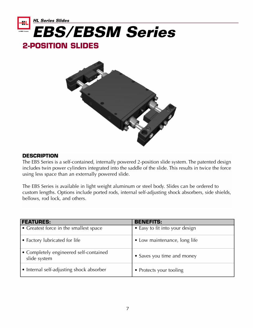
FEATURES:• Greatest force in the smallest space
• Factory lubricated for life
• Completely engineered self-containedslide system
• Internal self-adjusting shock absorber
BENEFITS:• Easy to fit into your design
• Low maintenance, long life
• Saves you time and money
• Protects your tooling
7
DESCRIPTIONThe EBS Series is a self-contained, internally powered 2-position slide system. The patented designincludes twin power cylinders integrated into the saddle of the slide. This results in twice the forceusing less space than an externally powered slide.
The EBS Series is available in light weight aluminum or steel body. Slides can be ordered to custom lengths. Options include ported rods, internal self-adjusting shock absorbers, side shields, bellows, rod lock, and others.
2-POSITION SLIDESEBS/EBSM Series
8
HL Series Slides
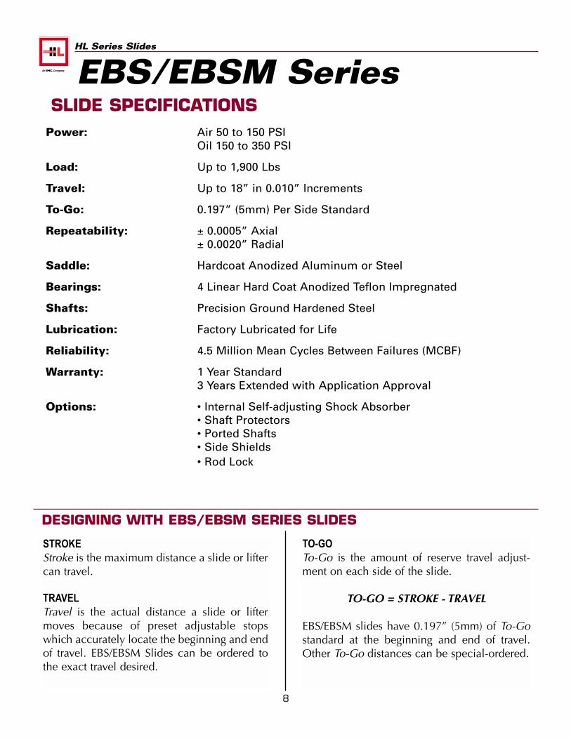
SLIDE SPECIFICATIONSPower: Air 50 to 150 PSI
Oil 150 to 350 PSI
Load: Up to 1,900 Lbs
Travel: Up to 18” in 0.010” Increments
To-Go: 0.197” (5mm) Per Side Standard
Repeatability: ± 0.0005” Axial± 0.0020” Radial
Saddle: Hardcoat Anodized Aluminum or Steel
Bearings: 4 Linear Hard Coat Anodized Teflon Impregnated
Shafts: Precision Ground Hardened Steel
Lubrication: Factory Lubricated for Life
Reliability: 4.5 Million Mean Cycles Between Failures (MCBF)
Warranty: 1 Year Standard3 Years Extended with Application Approval
Options: • Internal Self-adjusting Shock Absorber• Shaft Protectors• Ported Shafts• Side Shields• Rod Lock
STROKEStroke is the maximum distance a slide or liftercan travel.
TRAVELTravel is the actual distance a slide or liftermoves because of preset adjustable stopswhich accurately locate the beginning and endof travel. EBS/EBSM Slides can be ordered tothe exact travel desired.
TO-GOTo-Go is the amount of reserve travel adjust-ment on each side of the slide.
TO-GO = STROKE - TRAVEL
EBS/EBSM slides have 0.197” (5mm) of To-Gostandard at the beginning and end of travel.Other To-Go distances can be special-ordered.
DESIGNING WITH EBS/EBSM SERIES SLIDES
EBS/EBSM Series
9
HL Series Slides
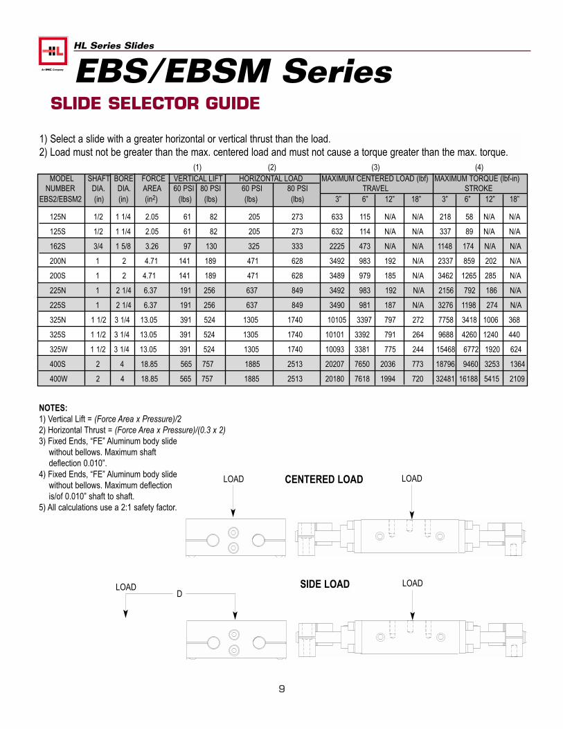
SLIDE SELECTOR GUIDE
MODEL SHAFT BORE FORCE VERTICAL LIFT HORIZONTAL LOAD MAXIMUM CENTERED LOAD (lbf) MAXIMUM TORQUE (lbf-in)NUMBER DIA. DIA. AREA 60 PSI 80 PSI 60 PSI 80 PSI TRAVEL STROKE
EBS2/EBSM2 (in) (in) (in2) (lbs) (lbs) (lbs) (lbs) 3” 6” 12” 18” 3” 6” 12” 18”
125N 1/2 1 1/4 2.05 61 82 205 273 633 115 N/A N/A 218 58 N/A N/A
125S 1/2 1 1/4 2.05 61 82 205 273 632 114 N/A N/A 337 89 N/A N/A
162S 3/4 1 5/8 3.26 97 130 325 333 2225 473 N/A N/A 1148 174 N/A N/A
200N 1 2 4.71 141 189 471 628 3492 983 192 N/A 2337 859 202 N/A
200S 1 2 4.71 141 189 471 628 3489 979 185 N/A 3462 1265 285 N/A
225N 1 2 1/4 6.37 191 256 637 849 3492 983 192 N/A 2156 792 186 N/A
225S 1 2 1/4 6.37 191 256 637 849 3490 981 187 N/A 3276 1198 274 N/A
325N 1 1/2 3 1/4 13.05 391 524 1305 1740 10105 3397 797 272 7758 3418 1006 368
325S 1 1/2 3 1/4 13.05 391 524 1305 1740 10101 3392 791 264 9688 4260 1240 440
325W 1 1/2 3 1/4 13.05 391 524 1305 1740 10093 3381 775 244 15468 6772 1920 624
400S 2 4 18.85 565 757 1885 2513 20207 7650 2036 773 18796 9460 3253 1364
400W 2 4 18.85 565 757 1885 2513 20180 7618 1994 720 32481 16188 5415 2109
CENTERED LOADLOAD LOAD
SIDE LOADLOAD LOADD
NOTES:1) Vertical Lift = (Force Area x Pressure)/22) Horizontal Thrust = (Force Area x Pressure)/(0.3 x 2)3) Fixed Ends, “FE” Aluminum body slide
without bellows. Maximum shaft deflection 0.010”.
4) Fixed Ends, “FE” Aluminum body slide without bellows. Maximum deflection is/of 0.010” shaft to shaft.
5) All calculations use a 2:1 safety factor.
1) Select a slide with a greater horizontal or vertical thrust than the load.2) Load must not be greater than the max. centered load and must not cause a torque greater than the max. torque.
(1) (2) (3) (4)
EBS/EBSM Series
LO
AD
(lb
f)
0
3600
4200
4800
5400
6000
6600
7200
7800
8400
9000
1 2 5 7 9 11TRAVEL (in)
.015
.010
.005
3 4 6 8 10
THRUST AT 60 PSI - 400 Series
12 13 14 15 16 17 18
3000
2400
1800
1200
600
LO
AD
(lb
f)
LO
AD
(lb
f)
0
600
1200
1800
2400
3000
3600
4200
4800
5400
6000
1 2 5 7 9 11TRAVEL (in)
.015
.010
.005
3 4 6 8 10
THRUST AT 60 PSI
12 13 14 15 16 17 18
LO
AD
(lb
f)
LO
AD
(lb
f)
0
300
600
900
1200
1500
1800
2100
2400
2700
3000
1 2 5 7 9 11TRAVEL (in)
THRUST AT 60 PSI - 225 Series
.015
.010
.005
THRUST AT 60 PSI - 200 Series
3 4 6 8 10
LO
AD
(lb
f)
10
HL Series Slides
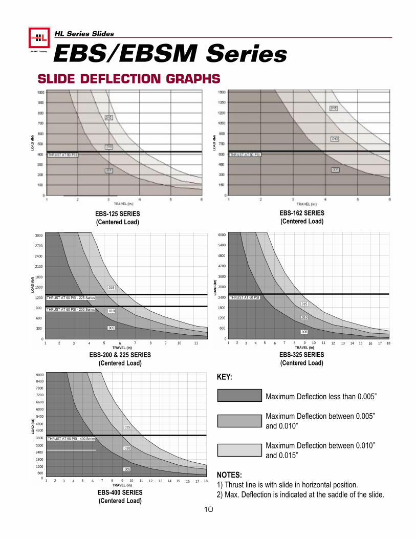
SLIDE DEFLECTION GRAPHS
EBS-125 SERIES(Centered Load)
EBS-162 SERIES(Centered Load)
EBS-200 & 225 SERIES(Centered Load)
EBS-325 SERIES(Centered Load)
EBS-400 SERIES(Centered Load)
KEY:
Maximum Deflection less than 0.005”
Maximum Deflection between 0.005” and 0.010”
Maximum Deflection between 0.010” and 0.015”
NOTES:1) Thrust line is with slide in horizontal position.2) Max. Deflection is indicated at the saddle of the slide.
EBS/EBSM SeriesLO
AD
(lb
f)
LOA
D (
lbf)
11
HL Series Slides
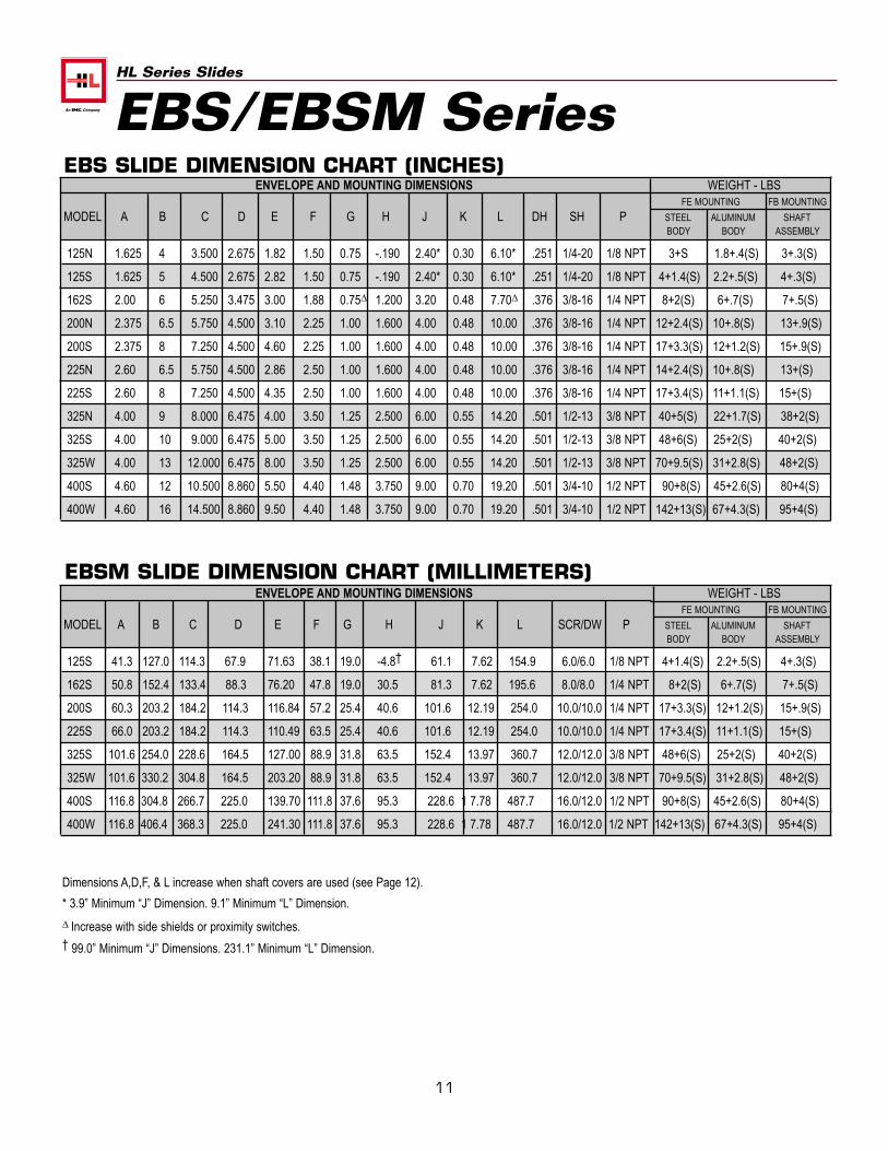
Dimensions A,D,F, & L increase when shaft covers are used (see Page 12).
* 3.9” Minimum “J” Dimension. 9.1” Minimum “L” Dimension.
∆ Increase with side shields or proximity switches.† 99.0” Minimum “J” Dimensions. 231.1” Minimum “L” Dimension.
ENVELOPE AND MOUNTING DIMENSIONS WEIGHT - LBSFE MOUNTING FB MOUNTING
MODEL A B C D E F G H J K L DH SH P STEEL ALUMINUM SHAFTBODY BODY ASSEMBLY
125N 1.625 4 3.500 2.675 1.82 1.50 0.75 -.190 2.40* 0.30 6.10* .251 1/4-20 1/8 NPT 3+S 1.8+.4(S) 3+.3(S)
125S 1.625 5 4.500 2.675 2.82 1.50 0.75 -.190 2.40* 0.30 6.10* .251 1/4-20 1/8 NPT 4+1.4(S) 2.2+.5(S) 4+.3(S)
162S 2.00 6 5.250 3.475 3.00 1.88 0.75∆ 1.200 3.20 0.48 7.70∆ .376 3/8-16 1/4 NPT 8+2(S) 6+.7(S) 7+.5(S)
200N 2.375 6.5 5.750 4.500 3.10 2.25 1.00 1.600 4.00 0.48 10.00 .376 3/8-16 1/4 NPT 12+2.4(S) 10+.8(S) 13+.9(S)
200S 2.375 8 7.250 4.500 4.60 2.25 1.00 1.600 4.00 0.48 10.00 .376 3/8-16 1/4 NPT 17+3.3(S) 12+1.2(S) 15+.9(S)
225N 2.60 6.5 5.750 4.500 2.86 2.50 1.00 1.600 4.00 0.48 10.00 .376 3/8-16 1/4 NPT 14+2.4(S) 10+.8(S) 13+(S)
225S 2.60 8 7.250 4.500 4.35 2.50 1.00 1.600 4.00 0.48 10.00 .376 3/8-16 1/4 NPT 17+3.4(S) 11+1.1(S) 15+(S)
325N 4.00 9 8.000 6.475 4.00 3.50 1.25 2.500 6.00 0.55 14.20 .501 1/2-13 3/8 NPT 40+5(S) 22+1.7(S) 38+2(S)
325S 4.00 10 9.000 6.475 5.00 3.50 1.25 2.500 6.00 0.55 14.20 .501 1/2-13 3/8 NPT 48+6(S) 25+2(S) 40+2(S)
325W 4.00 13 12.000 6.475 8.00 3.50 1.25 2.500 6.00 0.55 14.20 .501 1/2-13 3/8 NPT 70+9.5(S) 31+2.8(S) 48+2(S)
400S 4.60 12 10.500 8.860 5.50 4.40 1.48 3.750 9.00 0.70 19.20 .501 3/4-10 1/2 NPT 90+8(S) 45+2.6(S) 80+4(S)
400W 4.60 16 14.500 8.860 9.50 4.40 1.48 3.750 9.00 0.70 19.20 .501 3/4-10 1/2 NPT 142+13(S) 67+4.3(S) 95+4(S)
ENVELOPE AND MOUNTING DIMENSIONS WEIGHT - LBSFE MOUNTING FB MOUNTING
MODEL A B C D E F G H J K L SCR/DW P STEEL ALUMINUM SHAFTBODY BODY ASSEMBLY
125S 41.3 127.0 114.3 67.9 71.63 38.1 19.0 -4.8† 61.1 7.62 154.9 6.0/6.0 1/8 NPT 4+1.4(S) 2.2+.5(S) 4+.3(S)
162S 50.8 152.4 133.4 88.3 76.20 47.8 19.0 30.5 81.3 7.62 195.6 8.0/8.0 1/4 NPT 8+2(S) 6+.7(S) 7+.5(S)
200S 60.3 203.2 184.2 114.3 116.84 57.2 25.4 40.6 101.6 12.19 254.0 10.0/10.0 1/4 NPT 17+3.3(S) 12+1.2(S) 15+.9(S)
225S 66.0 203.2 184.2 114.3 110.49 63.5 25.4 40.6 101.6 12.19 254.0 10.0/10.0 1/4 NPT 17+3.4(S) 11+1.1(S) 15+(S)
325S 101.6 254.0 228.6 164.5 127.00 88.9 31.8 63.5 152.4 13.97 360.7 12.0/12.0 3/8 NPT 48+6(S) 25+2(S) 40+2(S)
325W 101.6 330.2 304.8 164.5 203.20 88.9 31.8 63.5 152.4 13.97 360.7 12.0/12.0 3/8 NPT 70+9.5(S) 31+2.8(S) 48+2(S)
400S 116.8 304.8 266.7 225.0 139.70 111.8 37.6 95.3 228.6 1 7.78 487.7 16.0/12.0 1/2 NPT 90+8(S) 45+2.6(S) 80+4(S)
400W 116.8 406.4 368.3 225.0 241.30 111.8 37.6 95.3 228.6 1 7.78 487.7 16.0/12.0 1/2 NPT 142+13(S) 67+4.3(S) 95+4(S)
EBS SLIDE DIMENSION CHART (INCHES)
EBSM SLIDE DIMENSION CHART (MILLIMETERS)
EBS/EBSM Series
12
HL Series Slides
OPTIONALPORT SIZE (P)
L + 2 x STROKE
G
FA
J + STROKEK
H + .5 xSTROKE
D + .5(STROKE)
H + .5 xSTROKE
SH (8 PLACES)
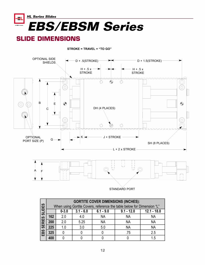
GORTITE COVER DIMENSIONS (INCHES):When using Gortite Covers, reference the table below for Dimension “L”
0-3.0 3.1 - 6.0 6.1 - 9.0 9.1 - 12.0 12.1 - 18.0162 2.0 4.0 NA NA NA200 2.0 5.25 NA NA NA225 1.0 3.0 5.0 NA NA325 0 0 0 .75 2.5400 0 0 0 0 1.5
EBS
SER
IES
SLID
ESSLIDE DIMENSIONS
E
C
B
DH (4 PLACES)
OPTIONAL SIDESHIELDS
EBS/EBSM Series
D + 1.5(STROKE)
STROKE = TRAVEL + “TO GO”
STANDARD PORT
13
HL Series Slides
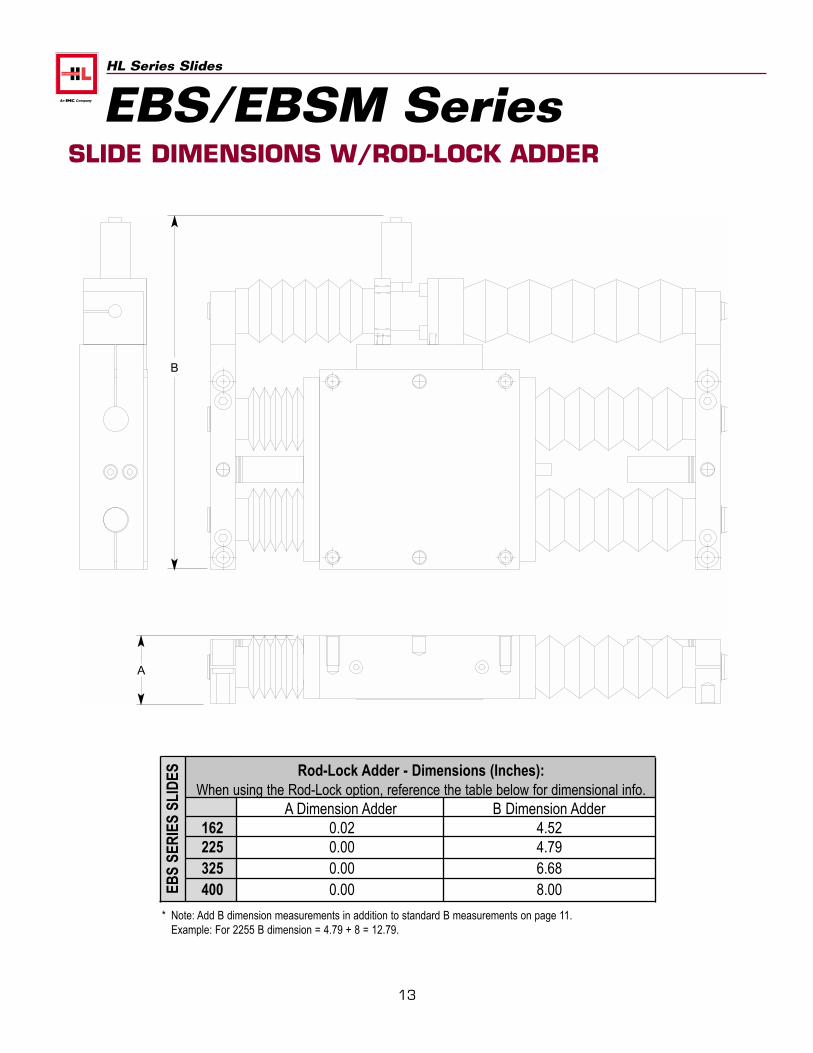
SLIDE DIMENSIONS W/ROD-LOCK ADDER
EBS/EBSM Series
Rod-Lock Adder - Dimensions (Inches):When using the Rod-Lock option, reference the table below for dimensional info.
A Dimension Adder B Dimension Adder162 0.02 4.52225 0.00 4.79325 0.00 6.68400 0.00 8.00EB
S SE
RIE
S SL
IDES
B
A
* Note: Add B dimension measurements in addition to standard B measurements on page 11.Example: For 2255 B dimension = 4.79 + 8 = 12.79.
14
HL Series Slides
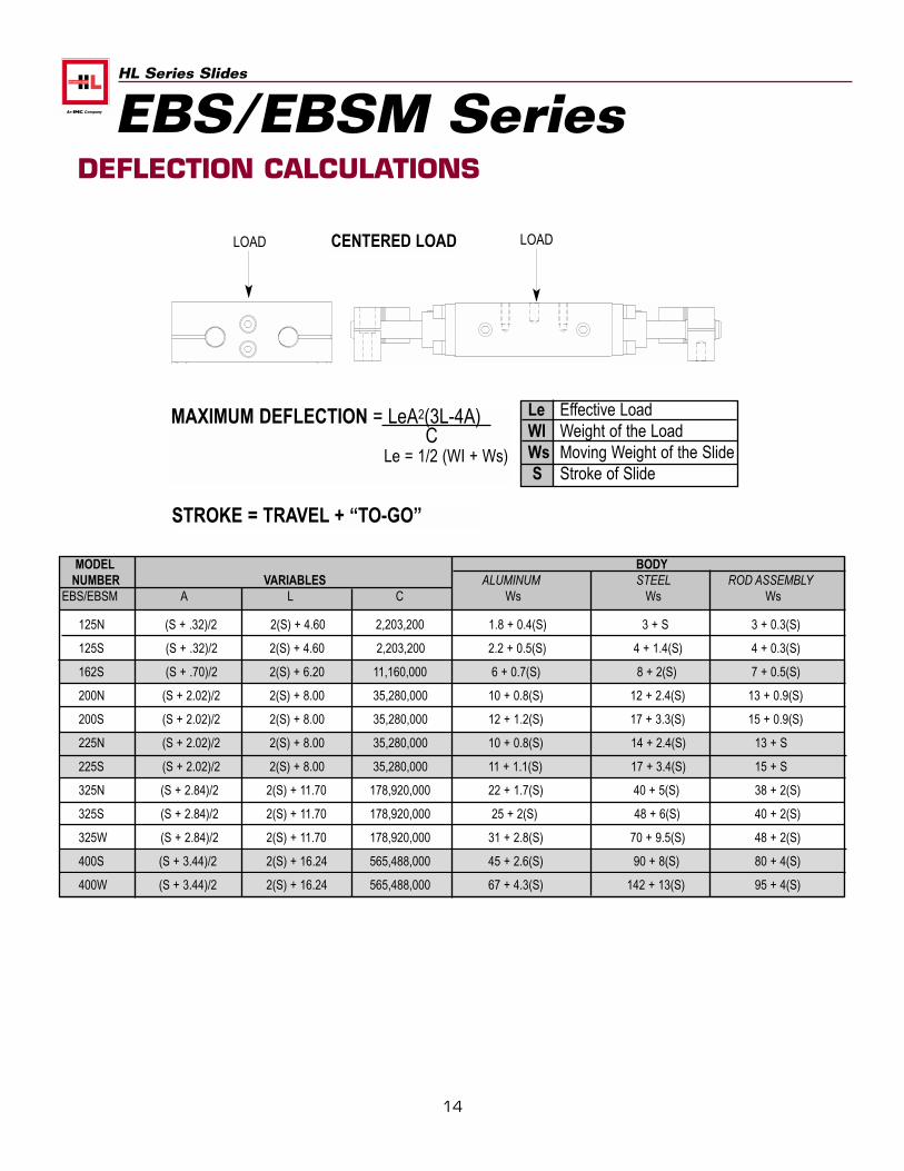
DEFLECTION CALCULATIONS
CENTERED LOADLOAD LOAD
MAXIMUM DEFLECTION = LeA2(3L-4A)C
Le = 1/2 (WI + Ws)
Le Effective LoadWI Weight of the LoadWs Moving Weight of the SlideS Stroke of Slide
MODEL BODYNUMBER VARIABLES ALUMINUM STEEL ROD ASSEMBLY
EBS/EBSM A L C Ws Ws Ws
125N (S + .32)/2 2(S) + 4.60 2,203,200 1.8 + 0.4(S) 3 + S 3 + 0.3(S)
125S (S + .32)/2 2(S) + 4.60 2,203,200 2.2 + 0.5(S) 4 + 1.4(S) 4 + 0.3(S)
162S (S + .70)/2 2(S) + 6.20 11,160,000 6 + 0.7(S) 8 + 2(S) 7 + 0.5(S)
200N (S + 2.02)/2 2(S) + 8.00 35,280,000 10 + 0.8(S) 12 + 2.4(S) 13 + 0.9(S)
200S (S + 2.02)/2 2(S) + 8.00 35,280,000 12 + 1.2(S) 17 + 3.3(S) 15 + 0.9(S)
225N (S + 2.02)/2 2(S) + 8.00 35,280,000 10 + 0.8(S) 14 + 2.4(S) 13 + S
225S (S + 2.02)/2 2(S) + 8.00 35,280,000 11 + 1.1(S) 17 + 3.4(S) 15 + S
325N (S + 2.84)/2 2(S) + 11.70 178,920,000 22 + 1.7(S) 40 + 5(S) 38 + 2(S)
325S (S + 2.84)/2 2(S) + 11.70 178,920,000 25 + 2(S) 48 + 6(S) 40 + 2(S)
325W (S + 2.84)/2 2(S) + 11.70 178,920,000 31 + 2.8(S) 70 + 9.5(S) 48 + 2(S)
400S (S + 3.44)/2 2(S) + 16.24 565,488,000 45 + 2.6(S) 90 + 8(S) 80 + 4(S)
400W (S + 3.44)/2 2(S) + 16.24 565,488,000 67 + 4.3(S) 142 + 13(S) 95 + 4(S)
EBS/EBSM Series
STROKE = TRAVEL + “TO-GO”
15
HL Series Slides
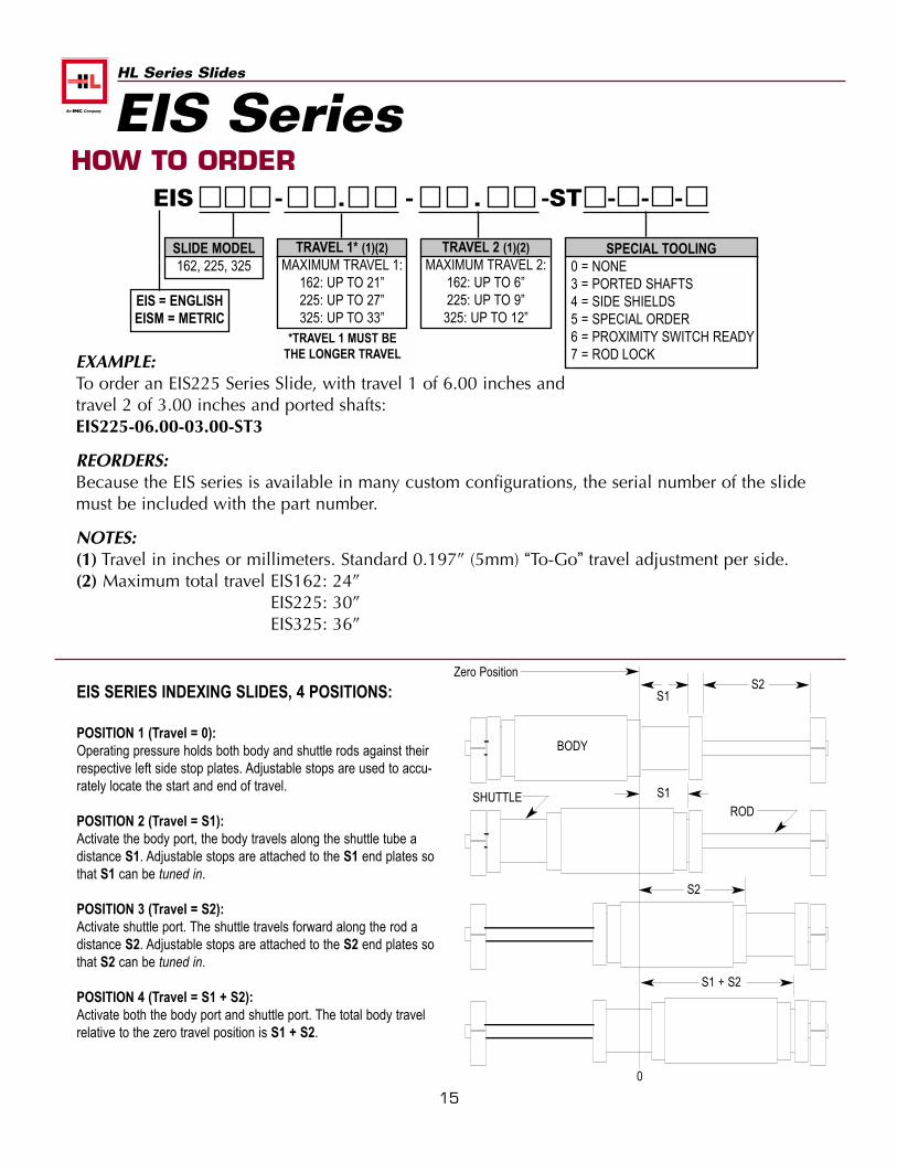
EIS - . - . -ST - - -
SLIDE MODEL162, 225, 325
TRAVEL 1* (1)(2)MAXIMUM TRAVEL 1:
162: UP TO 21”225: UP TO 27”325: UP TO 33”
SPECIAL TOOLING0 = NONE3 = PORTED SHAFTS4 = SIDE SHIELDS5 = SPECIAL ORDER6 = PROXIMITY SWITCH READY7 = ROD LOCK
*TRAVEL 1 MUST BETHE LONGER TRAVELEXAMPLE:
To order an EIS225 Series Slide, with travel 1 of 6.00 inches andtravel 2 of 3.00 inches and ported shafts:EIS225-06.00-03.00-ST3
REORDERS:Because the EIS series is available in many custom configurations, the serial number of the slidemust be included with the part number.
NOTES:(1) Travel in inches or millimeters. Standard 0.197” (5mm) “To-Go” travel adjustment per side.(2) Maximum total travel EIS162: 24”
EIS225: 30”EIS325: 36”
HOW TO ORDER
TRAVEL 2 (1)(2)MAXIMUM TRAVEL 2:
162: UP TO 6”225: UP TO 9”325: UP TO 12”
EIS SERIES INDEXING SLIDES, 4 POSITIONS:
POSITION 1 (Travel = 0):Operating pressure holds both body and shuttle rods against theirrespective left side stop plates. Adjustable stops are used to accu-rately locate the start and end of travel.
POSITION 2 (Travel = S1):Activate the body port, the body travels along the shuttle tube adistance S1. Adjustable stops are attached to the S1 end plates sothat S1 can be tuned in.
POSITION 3 (Travel = S2):Activate shuttle port. The shuttle travels forward along the rod adistance S2. Adjustable stops are attached to the S2 end plates sothat S2 can be tuned in.
POSITION 4 (Travel = S1 + S2):Activate both the body port and shuttle port. The total body travelrelative to the zero travel position is S1 + S2.
Zero Position
0
S2S1
BODY
SHUTTLE S1ROD
S2
S1 + S2
EIS Series
EIS = ENGLISHEISM = METRIC
16
HL Series Slides
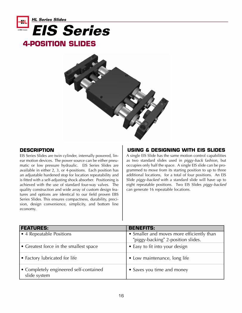
USING & DESIGNING WITH EIS SLIDESA single EIS Slide has the same motion control capabilitiesas two standard slides used in piggy-back fashion, butoccupies only half the space. A single EIS slide can be pro-grammed to move from its starting position to up to threeadditional locations, for a total of four positions. An EISSlide piggy-backed with a standard slide will have up toeight repeatable positions. Two EIS Slides piggy-backedcan generate 16 repeatable locations.
DESCRIPTIONEIS Series Slides are twin cylinder, internally powered, lin-ear motion devices. The power source can be either pneu-matic or low pressure hydraulic. EIS Series Slides areavailable in either 2, 3, or 4-positions. Each position hasan adjustable hardened stop for location repeatability andis fitted with a self-adjusting shock absorber. Positioning isachieved with the use of standard four-way valves. Thequality construction and wide array of custom design fea-tures and options are identical to our field proven EBSSeries Slides. This ensures compactness, durability, preci-sion, design convenience, simplicity, and bottom lineeconomy.
FEATURES:• 4 Repeatable Positions
• Greatest force in the smallest space
• Factory lubricated for life
• Completely engineered self-containedslide system
BENEFITS:• Smaller and moves more efficiently than
“piggy-backing” 2-position slides.• Easy to fit into your design
• Low maintenance, long life
• Saves you time and money
4-POSITION SLIDESEIS Series
17
HL Series Slides
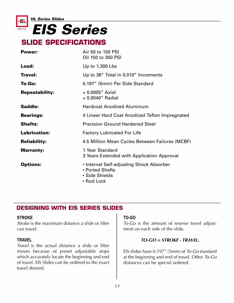
SLIDE SPECIFICATIONSPower: Air 50 to 150 PSI
Oil 150 to 350 PSI
Load: Up to 1,300 Lbs
Travel: Up to 36” Total in 0.010” Increments
To-Go: 0.197” (5mm) Per Side Standard
Repeatability: ± 0.0005” Axial± 0.0040” Radial
Saddle: Hardcoat Anodized Aluminum
Bearings: 4 Linear Hard Coat Anodized Teflon Impregnated
Shafts: Precision Ground Hardened Steel
Lubrication: Factory Lubricated For Life
Reliability: 4.5 Million Mean Cycles Between Failures (MCBF)
Warranty: 1 Year Standard3 Years Extended with Application Approval
Options: • Internal Self-adjusting Shock Absorber• Ported Shafts• Side Shields• Rod Lock
STROKEStroke is the maximum distance a slide or liftercan travel.
TRAVELTravel is the actual distance a slide or liftermoves because of preset adjustable stopswhich accurately locate the beginning and endof travel. EIS Slides can be ordered to the exacttravel desired.
TO-GOTo-Go is the amount of reserve travel adjust-ment on each side of the slide.
TO-GO = STROKE - TRAVEL.
EIS slides have 0.197” (5mm) of To-Go standardat the beginning and end of travel. Other To-Godistances can be special ordered.
DESIGNING WITH EIS SERIES SLIDES
EIS Series
18
HL Series Slides
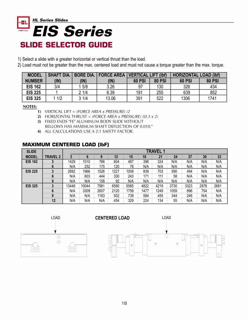
MODEL SHAFT DIA. BORE DIA. FORCE AREA VERTICAL LIFT (lbf) HORIZONTAL LOAD (lbf)NUMBER (IN) (IN) (IN) 60 PSI 80 PSI 60 PSI 80 PSIEIS 162 3/4 1 5/8 3.26 97 130 326 434EIS 225 1 2 1/4 6.39 191 255 639 852EIS 325 1 1/2 3 1/4 13.06 391 522 1306 1741
NOTES:1) VERTICAL LIFT = (FORCE AREA x PRESSURE) /22) HORIZONTAL THRUST = (FORCE AREA x PRESSURE) /(0.3 x 2)3) FIXED ENDS “FE” ALUMINUM BODY SLIDE WITHOUT
BELLOWS HAS MAXIMUM SHAFT DEFLECTION OF 0.010.”4) ALL CALCULATIONS USE A 2:1 SAFETY FACTOR.
SLIDE TRAVEL 1MODEL TRAVEL 2 3 6 9 12 15 18 21 24 27 30 33EIS 162 3 1429 1010 766 604 487 396 324 N/A N/A N/A N/A
6 N/A 252 175 120 76 N/A N/A N/A N/A N/A N/AEIS 225 3 2692 1966 1526 1227 1008 839 703 590 494 N/A N/A
6 N/A 603 444 330 243 171 111 58 N/A N/A N/A9 N/A N/A 158 92 N/A N/A N/A N/A N/A N/A N/A
EIS 325 3 13448 10044 7981 6590 5585 4822 4219 3730 3323 2978 26816 N/A 3309 2607 2120 1759 1477 1249 1059 896 754 N/A9 N/A N/A 1183 932 739 584 455 344 246 N/A N/A12 N/A N/A N/A 454 329 224 134 55 N/A N/A N/A
MAXIMUM CENTERED LOAD (lbF)
1) Select a slide with a greater horizontal or vertical thrust than the load.2) Load must not be greater than the max. centered load and must not cause a torque greater than the max. torque.
SLIDE SELECTOR GUIDE
CENTERED LOADLOAD LOAD
EIS Series
LO
AD
(lb
f)
0
600
1200
1800
2400
3000
3600
4200
4800
5400
6000
1 3 4 5 7 12TRAVEL STROKE 1 & STROKE 2 (in)
THRUST AT 60 PSI
2 6 8 9 10 11
.015
.010
.005
LO
AD
(lb
f)
19
HL Series Slides
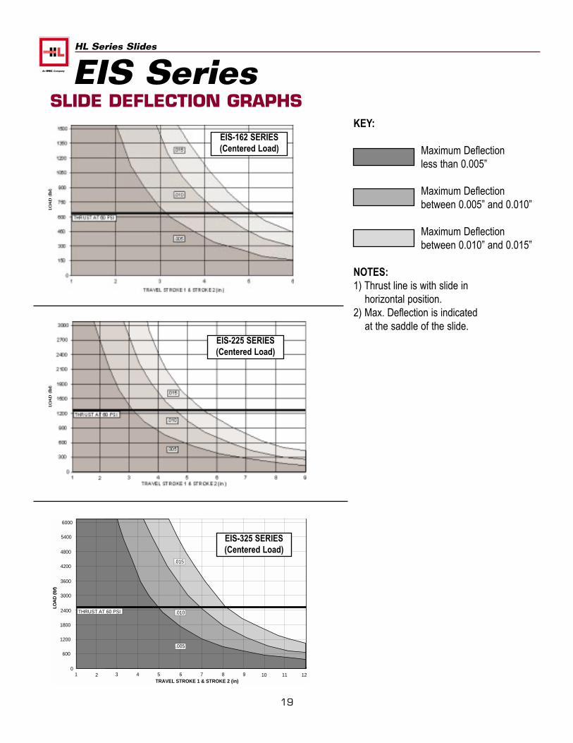
KEY:
Maximum Deflection less than 0.005”
Maximum Deflection between 0.005” and 0.010”
Maximum Deflection between 0.010” and 0.015”
NOTES:1) Thrust line is with slide in
horizontal position.2) Max. Deflection is indicated
at the saddle of the slide.
SLIDE DEFLECTION GRAPHS
EIS-162 SERIES(Centered Load)
EIS-225 SERIES(Centered Load)
EIS-325 SERIES(Centered Load)
EIS SeriesLO
AD
(lb
f)LO
AD
(lb
f)
20
HL Series Slides
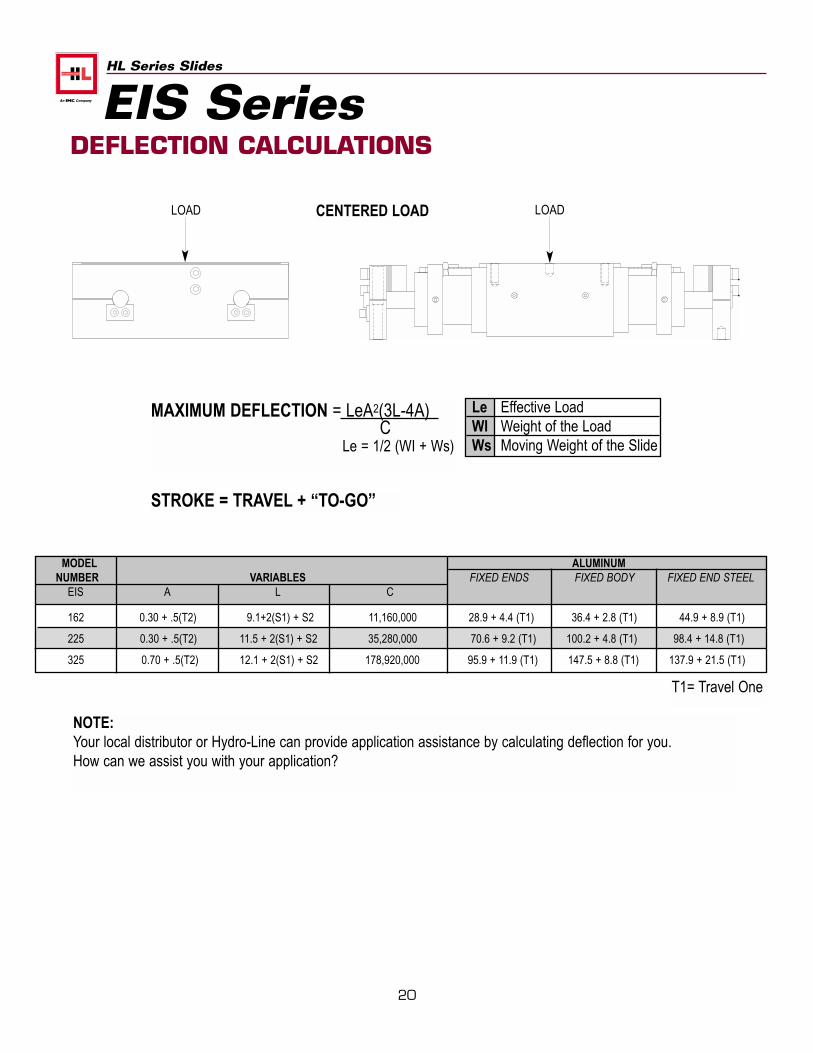
DEFLECTION CALCULATIONS
MAXIMUM DEFLECTION = LeA2(3L-4A)C
Le = 1/2 (WI + Ws)
Le Effective LoadWI Weight of the LoadWs Moving Weight of the Slide
MODEL ALUMINUMNUMBER VARIABLES FIXED ENDS FIXED BODY FIXED END STEEL
EIS A L C
162 0.30 + .5(T2) 9.1+2(S1) + S2 11,160,000 28.9 + 4.4 (T1) 36.4 + 2.8 (T1) 44.9 + 8.9 (T1)
225 0.30 + .5(T2) 11.5 + 2(S1) + S2 35,280,000 70.6 + 9.2 (T1) 100.2 + 4.8 (T1) 98.4 + 14.8 (T1)
325 0.70 + .5(T2) 12.1 + 2(S1) + S2 178,920,000 95.9 + 11.9 (T1) 147.5 + 8.8 (T1) 137.9 + 21.5 (T1)
CENTERED LOADLOAD LOAD
EIS Series
NOTE:Your local distributor or Hydro-Line can provide application assistance by calculating deflection for you.How can we assist you with your application?
STROKE = TRAVEL + “TO-GO”
T1= Travel One
21
HL Series Slides
OPTIONALNPT PORTS
NPTF PORTS4 PLACES TYP.
A
BCE
G J + S1
L + 2(S1) + S2
H+.5(S1)
D + .5(S1)
L + 2(S1) + S2 - G
SH(8 PLACES)
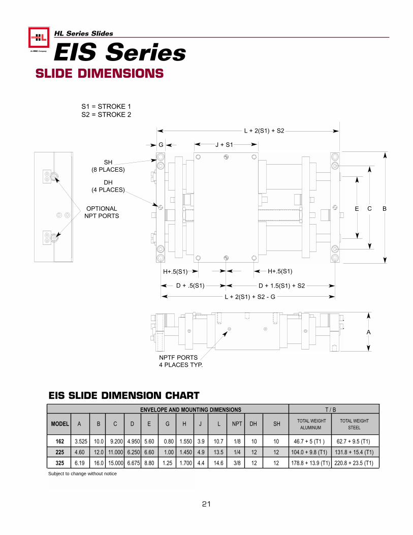
SLIDE DIMENSIONS
EIS SLIDE DIMENSION CHARTENVELOPE AND MOUNTING DIMENSIONS T / B
MODEL A B C D E G H J L NPT DH SH TOTAL WEIGHT TOTAL WEIGHT
ALUMINUM STEEL
162 3.525 10.0 9.200 4.950 5.60 0.80 1.550 3.9 10.7 1/8 10 10 46.7 + 5 (T1 ) 62.7 + 9.5 (T1)
225 4.60 12.0 11.000 6.250 6.60 1.00 1.450 4.9 13.5 1/4 12 12 104.0 + 9.8 (T1) 131.8 + 15.4 (T1)
325 6.19 16.0 15.000 6.675 8.80 1.25 1.700 4.4 14.6 3/8 12 12 178.8 + 13.9 (T1) 220.8 + 23.5 (T1)
EIS Series
H+.5(S1)
D + 1.5(S1) + S2
DH(4 PLACES)
Subject to change without notice
S1 = STROKE 1S2 = STROKE 2
22
HL Series Slides
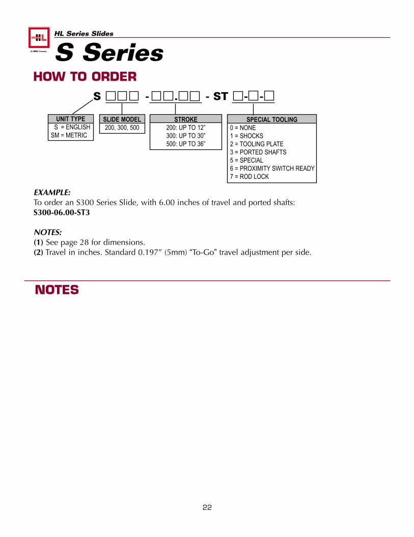
S - . - ST - -
SLIDE MODEL200, 300, 500
UNIT TYPES = ENGLISH
SM = METRIC
STROKE200: UP TO 12”300: UP TO 30”500: UP TO 36”
SPECIAL TOOLING0 = NONE1 = SHOCKS2 = TOOLING PLATE3 = PORTED SHAFTS5 = SPECIAL6 = PROXIMITY SWITCH READY7 = ROD LOCK
EXAMPLE:To order an S300 Series Slide, with 6.00 inches of travel and ported shafts: S300-06.00-ST3
NOTES:(1) See page 28 for dimensions.(2) Travel in inches. Standard 0.197” (5mm) “To-Go” travel adjustment per side.
HOW TO ORDER
NOTES
S Series
23
HL Series Slides
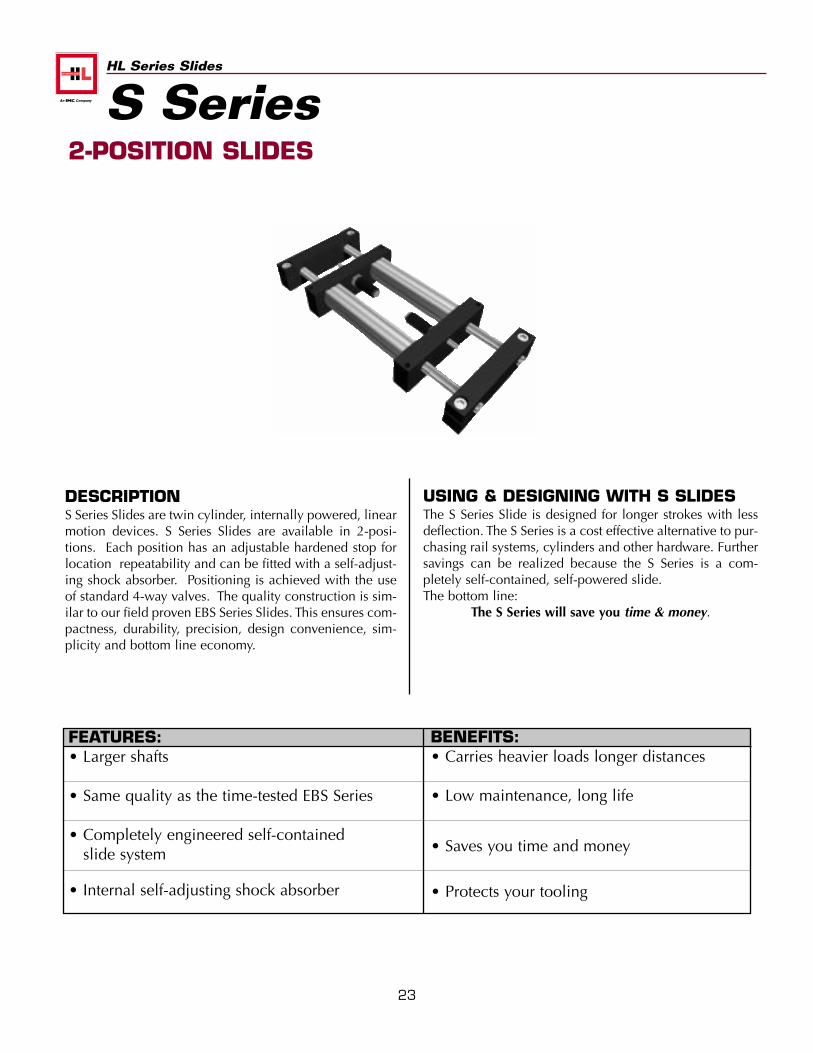
USING & DESIGNING WITH S SLIDESThe S Series Slide is designed for longer strokes with lessdeflection. The S Series is a cost effective alternative to pur-chasing rail systems, cylinders and other hardware. Furthersavings can be realized because the S Series is a com-pletely self-contained, self-powered slide. The bottom line:
The S Series will save you time & money.
DESCRIPTIONS Series Slides are twin cylinder, internally powered, linearmotion devices. S Series Slides are available in 2-posi-tions. Each position has an adjustable hardened stop forlocation repeatability and can be fitted with a self-adjust-ing shock absorber. Positioning is achieved with the useof standard 4-way valves. The quality construction is sim-ilar to our field proven EBS Series Slides. This ensures com-pactness, durability, precision, design convenience, sim-plicity and bottom line economy.
FEATURES:• Larger shafts
• Same quality as the time-tested EBS Series
• Completely engineered self-containedslide system
• Internal self-adjusting shock absorber
BENEFITS:• Carries heavier loads longer distances
• Low maintenance, long life
• Saves you time and money
• Protects your tooling
2-POSITION SLIDES
S Series
24
HL Series Slides
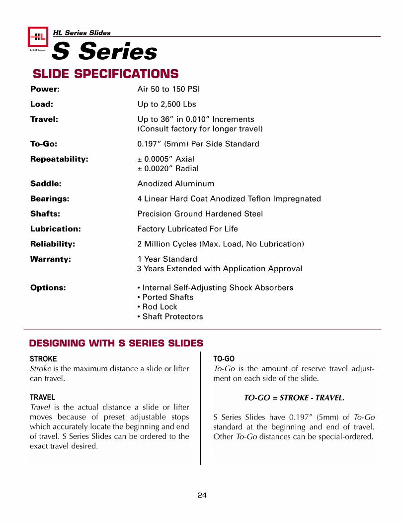
SLIDE SPECIFICATIONSPower: Air 50 to 150 PSI
Load: Up to 2,500 Lbs
Travel: Up to 36” in 0.010” Increments(Consult factory for longer travel)
To-Go: 0.197” (5mm) Per Side Standard
Repeatability: ± 0.0005” Axial± 0.0020” Radial
Saddle: Anodized Aluminum
Bearings: 4 Linear Hard Coat Anodized Teflon Impregnated
Shafts: Precision Ground Hardened Steel
Lubrication: Factory Lubricated For Life
Reliability: 2 Million Cycles (Max. Load, No Lubrication)
Warranty: 1 Year Standard3 Years Extended with Application Approval
Options: • Internal Self-Adjusting Shock Absorbers• Ported Shafts• Rod Lock• Shaft Protectors
STROKEStroke is the maximum distance a slide or liftercan travel.
TRAVELTravel is the actual distance a slide or liftermoves because of preset adjustable stopswhich accurately locate the beginning and endof travel. S Series Slides can be ordered to theexact travel desired.
TO-GOTo-Go is the amount of reserve travel adjust-ment on each side of the slide.
TO-GO = STROKE - TRAVEL.
S Series Slides have 0.197” (5mm) of To-Gostandard at the beginning and end of travel.Other To-Go distances can be special-ordered.
DESIGNING WITH S SERIES SLIDES
S Series
25
HL Series Slides
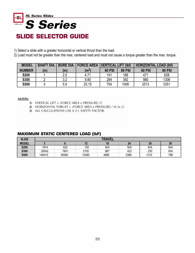
MODEL SHAFT DIA. BORE DIA. FORCE AREA VERTICAL LIFT (lbf) HORIZONTAL LOAD (lbf)NUMBER (in) (in) (in2) 60 PSI 80 PSI 60 PSI 80 PSI
S200 1 2.0 4.71 141 188 471 628S300 2 3.2 9.80 294 392 980 1306S500 3 5.0 25.15 754 1006 2513 3351
NOTES:1) VERTICAL LIFT = (FORCE AREA x PRESSURE) /22) HORIZONTAL THRUST = (FORCE AREA x PRESSURE) / (0.3x 2)3) ALL CALCULATIONS USE A 2:1 SAFETY FACTOR.
SLIDE TRAVELMODEL 3 6 12 18 24 30 36
S200 1814 632 150 N/A N/A N/A N/AS300 20042 7841 2155 867 423 230 N/AS500 146410 50060 12480 4866 2366 1310 788
MAXIMUM STATIC CENTERED LOAD (lbF)
1) Select a slide with a greater horizontal or vertical thrust than the load.2) Load must not be greater than the max. centered load and must not cause a torque greater than the max. torque.
SLIDE SELECTOR GUIDE
S Series
26
HL Series Slides
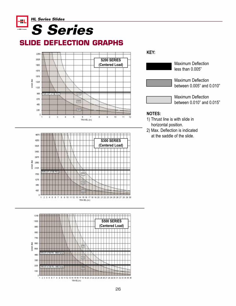
KEY:
Maximum Deflection less than 0.005”
Maximum Deflection between 0.005” and 0.010”
Maximum Deflection between 0.010” and 0.015”
NOTES:1) Thrust line is with slide in
horizontal position.2) Max. Deflection is indicated
at the saddle of the slide.
SLIDE DEFLECTION GRAPHS
S200 SERIES(Centered Load)
S300 SERIES(Centered Load)
S500 SERIES(Centered Load)
S SeriesLO
AD
(lb
f)LO
AD
(lb
f)LO
AD
(lb
f)
27
HL Series Slides
DEFLECTION CALCULATIONS
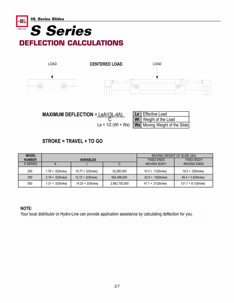
MAXIMUM DEFLECTION = LeA2(3L-4A)C
Le = 1/2 (WI + Ws)
Le Effective LoadWI Weight of the LoadWs Moving Weight of the Slide
MODEL MOVING WEIGHT OF SLIDE (Ws)NUMBER VARIABLES FIXED ENDS FIXED BODYS SERIES A L C MOVING BODY MOVING ENDS
200 1.78 + .5(Stroke) 10.77 + 2(Stroke) 35,280,000 10.3 + .11(Stroke) 16.5 + .9(Stroke)
300 2.19 + .5(Stroke) 12.72 + 2(Stroke) 565,488,000 20.8 + .19(Stroke) 49.4 + 3.6(Stroke)
500 1.31 + .5(Stroke) 14.25 + 2(Stroke) 2,862,792,000 47.1 + .31(Stroke) 131.7 + 8.1(Stroke)
CENTERED LOADLOAD LOAD
S Series
NOTE:Your local distributor or Hydro-Line can provide application assistance by calculating deflection for you.
STROKE = TRAVEL + TO GO
28
HL Series Slides
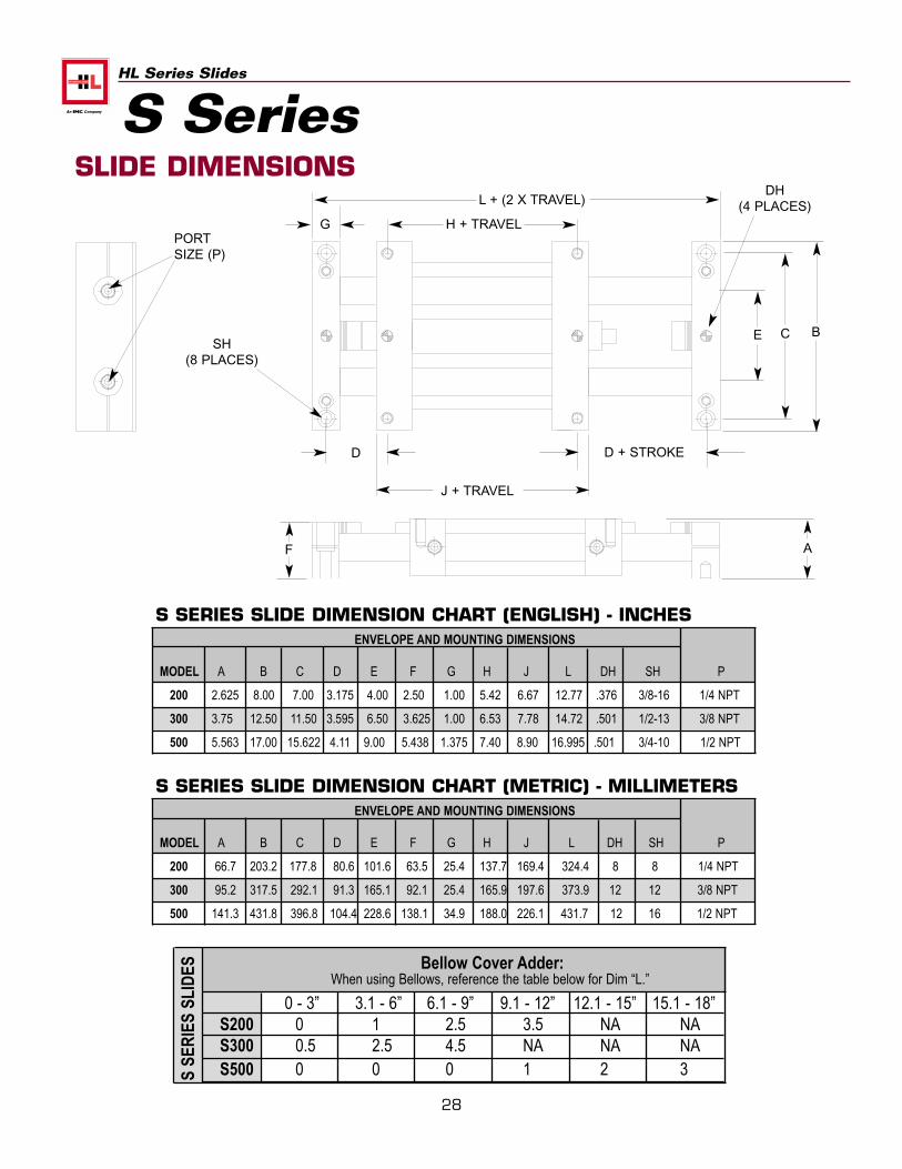
SLIDE DIMENSIONS
S SERIES SLIDE DIMENSION CHART (ENGLISH) - INCHESENVELOPE AND MOUNTING DIMENSIONS
MODEL A B C D E F G H J L DH SH P
200 2.625 8.00 7.00 3.175 4.00 2.50 1.00 5.42 6.67 12.77 .376 3/8-16 1/4 NPT
300 3.75 12.50 11.50 3.595 6.50 3.625 1.00 6.53 7.78 14.72 .501 1/2-13 3/8 NPT
500 5.563 17.00 15.622 4.11 9.00 5.438 1.375 7.40 8.90 16.995 .501 3/4-10 1/2 NPT
PORTSIZE (P)
A
BCE
H + TRAVEL
L + (2 X TRAVEL)
J + TRAVEL
D
SH(8 PLACES)
F
D + STROKE
S SeriesDH
(4 PLACES)G
S SERIES SLIDE DIMENSION CHART (METRIC) - MILLIMETERSENVELOPE AND MOUNTING DIMENSIONS
MODEL A B C D E F G H J L DH SH P
200 66.7 203.2 177.8 80.6 101.6 63.5 25.4 137.7 169.4 324.4 8 8 1/4 NPT
300 95.2 317.5 292.1 91.3 165.1 92.1 25.4 165.9 197.6 373.9 12 12 3/8 NPT
500 141.3 431.8 396.8 104.4 228.6 138.1 34.9 188.0 226.1 431.7 12 16 1/2 NPT
0 - 3” 3.1 - 6” 6.1 - 9” 9.1 - 12” 12.1 - 15” 15.1 - 18”S200 0 1 2.5 3.5 NA NAS300 0.5 2.5 4.5 NA NA NAS500 0 0 0 1 2 3S
SER
IES
SLID
ES Bellow Cover Adder:When using Bellows, reference the table below for Dim “L.”
29
HL Series Slides
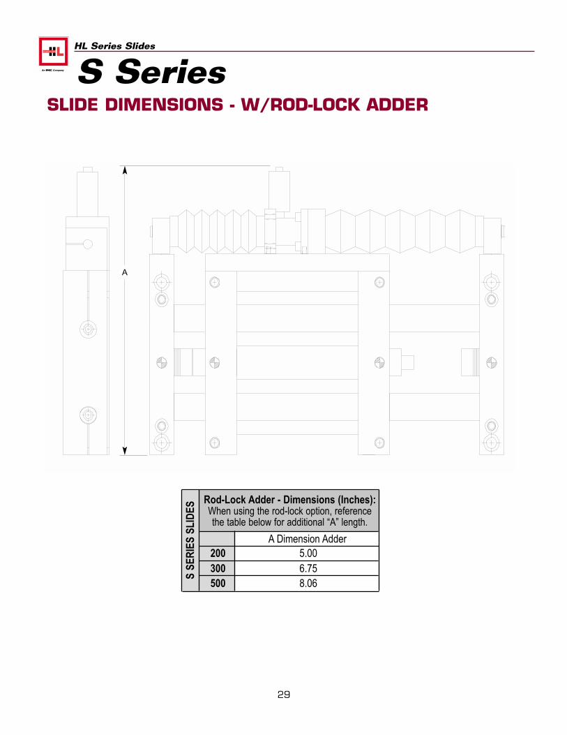
SLIDE DIMENSIONS - W/ROD-LOCK ADDER
S Series
Rod-Lock Adder - Dimensions (Inches):When using the rod-lock option, referencethe table below for additional “A” length.
A Dimension Adder200 5.00300 6.75500 8.06
S SE
RIE
S SL
IDES
A
30
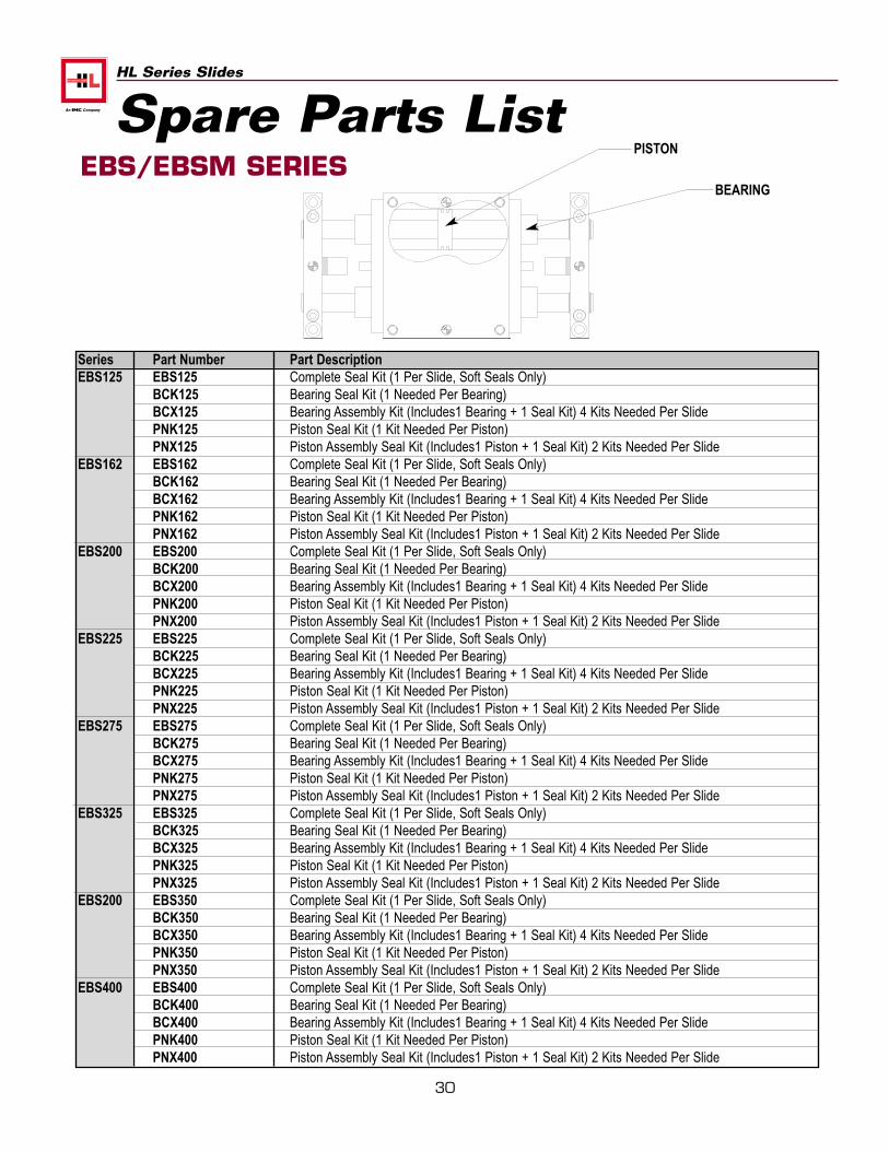
HL Series Slides
Spare Parts ListEBS/EBSM SERIES
Series Part Number Part DescriptionEBS125 EBS125 Complete Seal Kit (1 Per Slide, Soft Seals Only)
BCK125 Bearing Seal Kit (1 Needed Per Bearing)BCX125 Bearing Assembly Kit (Includes1 Bearing + 1 Seal Kit) 4 Kits Needed Per SlidePNK125 Piston Seal Kit (1 Kit Needed Per Piston)PNX125 Piston Assembly Seal Kit (Includes1 Piston + 1 Seal Kit) 2 Kits Needed Per Slide
EBS162 EBS162 Complete Seal Kit (1 Per Slide, Soft Seals Only)BCK162 Bearing Seal Kit (1 Needed Per Bearing)BCX162 Bearing Assembly Kit (Includes1 Bearing + 1 Seal Kit) 4 Kits Needed Per SlidePNK162 Piston Seal Kit (1 Kit Needed Per Piston)PNX162 Piston Assembly Seal Kit (Includes1 Piston + 1 Seal Kit) 2 Kits Needed Per Slide
EBS200 EBS200 Complete Seal Kit (1 Per Slide, Soft Seals Only)BCK200 Bearing Seal Kit (1 Needed Per Bearing)BCX200 Bearing Assembly Kit (Includes1 Bearing + 1 Seal Kit) 4 Kits Needed Per SlidePNK200 Piston Seal Kit (1 Kit Needed Per Piston)PNX200 Piston Assembly Seal Kit (Includes1 Piston + 1 Seal Kit) 2 Kits Needed Per Slide
EBS225 EBS225 Complete Seal Kit (1 Per Slide, Soft Seals Only)BCK225 Bearing Seal Kit (1 Needed Per Bearing)BCX225 Bearing Assembly Kit (Includes1 Bearing + 1 Seal Kit) 4 Kits Needed Per SlidePNK225 Piston Seal Kit (1 Kit Needed Per Piston)PNX225 Piston Assembly Seal Kit (Includes1 Piston + 1 Seal Kit) 2 Kits Needed Per Slide
EBS275 EBS275 Complete Seal Kit (1 Per Slide, Soft Seals Only)BCK275 Bearing Seal Kit (1 Needed Per Bearing)BCX275 Bearing Assembly Kit (Includes1 Bearing + 1 Seal Kit) 4 Kits Needed Per SlidePNK275 Piston Seal Kit (1 Kit Needed Per Piston)PNX275 Piston Assembly Seal Kit (Includes1 Piston + 1 Seal Kit) 2 Kits Needed Per Slide
EBS325 EBS325 Complete Seal Kit (1 Per Slide, Soft Seals Only)BCK325 Bearing Seal Kit (1 Needed Per Bearing)BCX325 Bearing Assembly Kit (Includes1 Bearing + 1 Seal Kit) 4 Kits Needed Per SlidePNK325 Piston Seal Kit (1 Kit Needed Per Piston)PNX325 Piston Assembly Seal Kit (Includes1 Piston + 1 Seal Kit) 2 Kits Needed Per Slide
EBS200 EBS350 Complete Seal Kit (1 Per Slide, Soft Seals Only)BCK350 Bearing Seal Kit (1 Needed Per Bearing)BCX350 Bearing Assembly Kit (Includes1 Bearing + 1 Seal Kit) 4 Kits Needed Per SlidePNK350 Piston Seal Kit (1 Kit Needed Per Piston)PNX350 Piston Assembly Seal Kit (Includes1 Piston + 1 Seal Kit) 2 Kits Needed Per Slide
EBS400 EBS400 Complete Seal Kit (1 Per Slide, Soft Seals Only)BCK400 Bearing Seal Kit (1 Needed Per Bearing)BCX400 Bearing Assembly Kit (Includes1 Bearing + 1 Seal Kit) 4 Kits Needed Per SlidePNK400 Piston Seal Kit (1 Kit Needed Per Piston)PNX400 Piston Assembly Seal Kit (Includes1 Piston + 1 Seal Kit) 2 Kits Needed Per Slide
PISTON
BEARING
31
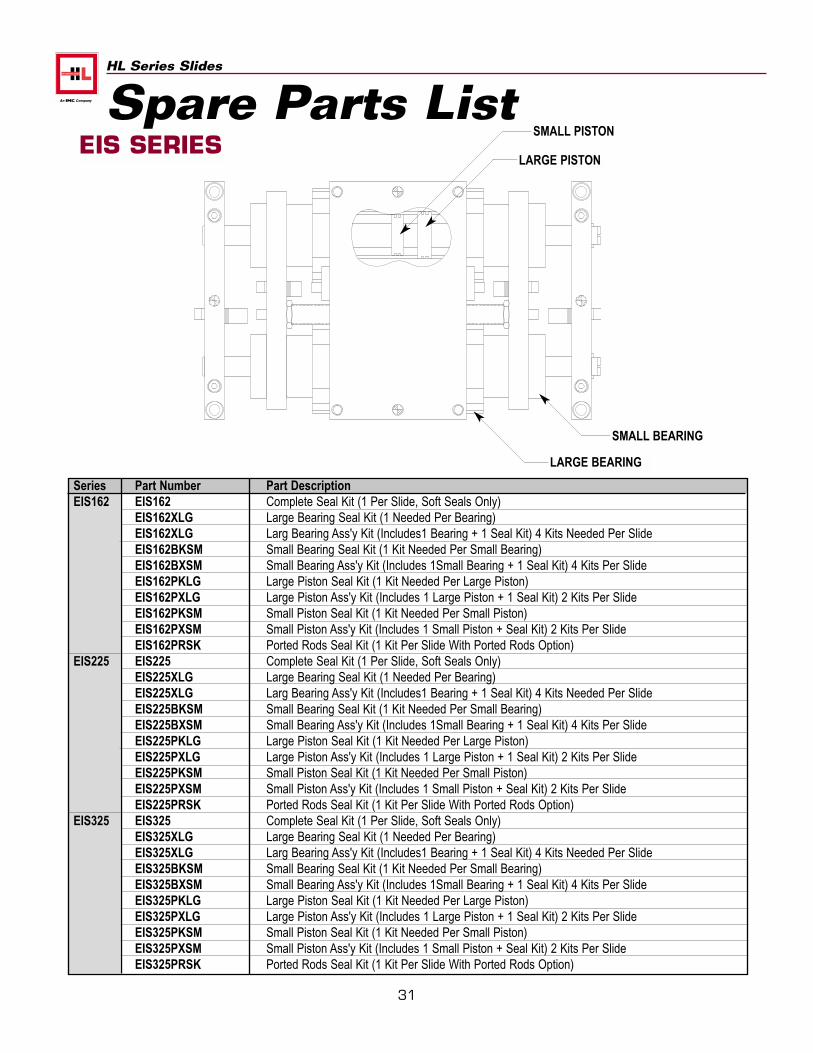
HL Series Slides
Spare Parts ListEIS SERIES
Series Part Number Part DescriptionEIS162 EIS162 Complete Seal Kit (1 Per Slide, Soft Seals Only)
EIS162XLG Large Bearing Seal Kit (1 Needed Per Bearing)EIS162XLG Larg Bearing Ass'y Kit (Includes1 Bearing + 1 Seal Kit) 4 Kits Needed Per SlideEIS162BKSM Small Bearing Seal Kit (1 Kit Needed Per Small Bearing)EIS162BXSM Small Bearing Ass'y Kit (Includes 1Small Bearing + 1 Seal Kit) 4 Kits Per SlideEIS162PKLG Large Piston Seal Kit (1 Kit Needed Per Large Piston)EIS162PXLG Large Piston Ass'y Kit (Includes 1 Large Piston + 1 Seal Kit) 2 Kits Per SlideEIS162PKSM Small Piston Seal Kit (1 Kit Needed Per Small Piston)EIS162PXSM Small Piston Ass'y Kit (Includes 1 Small Piston + Seal Kit) 2 Kits Per SlideEIS162PRSK Ported Rods Seal Kit (1 Kit Per Slide With Ported Rods Option)
EIS225 EIS225 Complete Seal Kit (1 Per Slide, Soft Seals Only)EIS225XLG Large Bearing Seal Kit (1 Needed Per Bearing)EIS225XLG Larg Bearing Ass'y Kit (Includes1 Bearing + 1 Seal Kit) 4 Kits Needed Per SlideEIS225BKSM Small Bearing Seal Kit (1 Kit Needed Per Small Bearing)EIS225BXSM Small Bearing Ass'y Kit (Includes 1Small Bearing + 1 Seal Kit) 4 Kits Per SlideEIS225PKLG Large Piston Seal Kit (1 Kit Needed Per Large Piston)EIS225PXLG Large Piston Ass'y Kit (Includes 1 Large Piston + 1 Seal Kit) 2 Kits Per SlideEIS225PKSM Small Piston Seal Kit (1 Kit Needed Per Small Piston)EIS225PXSM Small Piston Ass'y Kit (Includes 1 Small Piston + Seal Kit) 2 Kits Per SlideEIS225PRSK Ported Rods Seal Kit (1 Kit Per Slide With Ported Rods Option)
EIS325 EIS325 Complete Seal Kit (1 Per Slide, Soft Seals Only)EIS325XLG Large Bearing Seal Kit (1 Needed Per Bearing)EIS325XLG Larg Bearing Ass'y Kit (Includes1 Bearing + 1 Seal Kit) 4 Kits Needed Per SlideEIS325BKSM Small Bearing Seal Kit (1 Kit Needed Per Small Bearing)EIS325BXSM Small Bearing Ass'y Kit (Includes 1Small Bearing + 1 Seal Kit) 4 Kits Per SlideEIS325PKLG Large Piston Seal Kit (1 Kit Needed Per Large Piston)EIS325PXLG Large Piston Ass'y Kit (Includes 1 Large Piston + 1 Seal Kit) 2 Kits Per SlideEIS325PKSM Small Piston Seal Kit (1 Kit Needed Per Small Piston)EIS325PXSM Small Piston Ass'y Kit (Includes 1 Small Piston + Seal Kit) 2 Kits Per SlideEIS325PRSK Ported Rods Seal Kit (1 Kit Per Slide With Ported Rods Option)
SMALL PISTON
LARGE PISTON
SMALL BEARING
LARGE BEARING
32
HL Series Slides
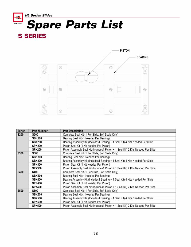
Spare Parts ListS SERIES
Series Part Number Part DescriptionS200 S200 Complete Seal Kit (1 Per Slide, Soft Seals Only)
SBK200 Bearing Seal Kit (1 Needed Per Bearing)SBX200 Bearing Assembly Kit (Includes1 Bearing + 1 Seal Kit) 4 Kits Needed Per SlideSPK200 Piston Seal Kit (1 Kit Needed Per Piston)SPX200 Piston Assembly Seal Kit (Includes1 Piston + 1 Seal Kit) 2 Kits Needed Per Slide
S300 S300 Complete Seal Kit (1 Per Slide, Soft Seals Only)SBK300 Bearing Seal Kit (1 Needed Per Bearing)SBX200 Bearing Assembly Kit (Includes1 Bearing + 1 Seal Kit) 4 Kits Needed Per SlideSPK300 Piston Seal Kit (1 Kit Needed Per Piston)SPX300 Piston Assembly Seal Kit (Includes1 Piston + 1 Seal Kit) 2 Kits Needed Per Slide
S400 S400 Complete Seal Kit (1 Per Slide, Soft Seals Only)SBK400 Bearing Seal Kit (1 Needed Per Bearing)SBX400 Bearing Assembly Kit (Includes1 Bearing + 1 Seal Kit) 4 Kits Needed Per SlideSPK400 Piston Seal Kit (1 Kit Needed Per Piston)SPX400 Piston Assembly Seal Kit (Includes1 Piston + 1 Seal Kit) 2 Kits Needed Per Slide
S500 S500 Complete Seal Kit (1 Per Slide, Soft Seals Only)SBK500 Bearing Seal Kit (1 Needed Per Bearing)SBX500 Bearing Assembly Kit (Includes1 Bearing + 1 Seal Kit) 4 Kits Needed Per SlideSPK500 Piston Seal Kit (1 Kit Needed Per Piston)SPX500 Piston Assembly Seal Kit (Includes1 Piston + 1 Seal Kit) 2 Kits Needed Per Slide
PISTON
BEARING

33
HL Series Slides
Notes
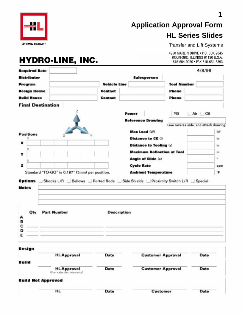
HYDRO-LINE, INC.
1Application Approval Form
HL Series SlidesTransfer and Lift Systems
4950 MARLIN DRIVE • P.O. BOX 2045ROCKFORD, ILLINOIS 61130 U.S.A.815-654-9050 • FAX 815-654-3393
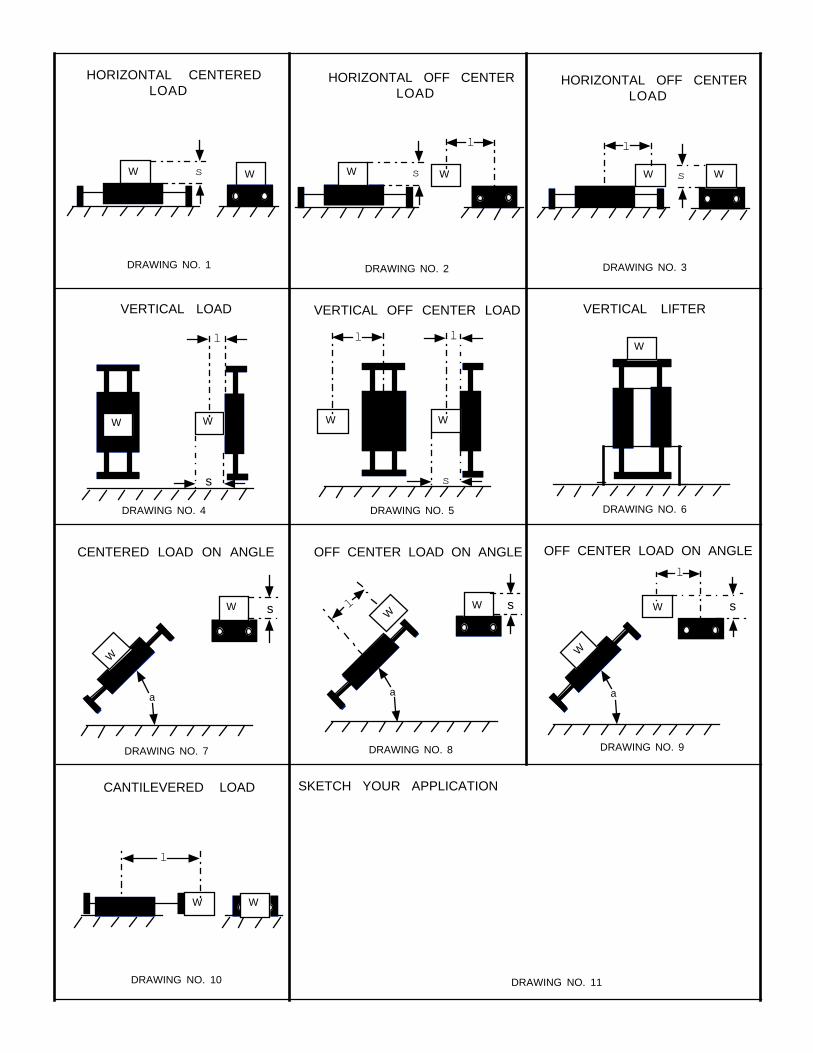
HORIZONTAL CENTEREDLOAD
l
W WWW
HORIZONTAL OFF CENTERLOAD
WW
l
HORIZONTAL OFF CENTERLOAD
WW
l
VERTICAL LOAD
WW
ll
VERTICAL OFF CENTER LOAD
W
VERTICAL LIFTER
W
W
WW
W
W
l
l
W W
l
CENTERED LOAD ON ANGLE OFF CENTER LOAD ON ANGLE OFF CENTER LOAD ON ANGLE
CANTILEVERED LOAD SKETCH YOUR APPLICATION
DRAWING NO. 1 DRAWING NO. 2 DRAWING NO. 3
DRAWING NO. 4 DRAWING NO. 5 DRAWING NO. 6
DRAWING NO. 7 DRAWING NO. 8 DRAWING NO. 9
DRAWING NO. 10 DRAWING NO. 11
s s s
s s
a a
s s s
a
HYDRO-LINE, INC.
HL SlidesTransfer and Lift Systems
RO
CKFORD, IL
Delivering Engineered Solutionsin Actuation Worldwide
REV. 4/00 10,000 CG
HYDRO-LINE Actuation Products
HM SERIES CYLINDERS• Conform to international metric
specifications ISO 6020/2 andDIN 24 554
• 25 mm to 200 mm bore sizes• 210 BAR nominal hydraulic• All steel construction
ROCKFORD SERIESCYLINDERS• ASAE interchangeable
agricultural cylinders• Rockford 2500–2500 psi hydraulic• Rockford 3000–3000 psi hydraulic
ELECTRONIC FEEDBACKCYLINDERSHydraulic or pneumatic cylinderswhich incorporate cylinder positionsensing and feedback throughoutthe stroke. Available in N5, R5,A5, Q5, HM, HW, SM or specialcylinders.
SERIES 20/30 BOOSTERS• Standard series to 5000 psi output• Custom designs to 20,000 psi T SERIES AIR/OIL TANKS• All steel constructionQT SERIES AIR/OIL TANKS• Aluminum end caps and translucent
tubing
N5 SERIES CYLINDERS• NFPA interchangeable• N5 – 3000 psi nominal hydraulic• AN5 – to 250 psi very heavy-
duty pneumatic• LAN5 – to 250 psi very heavy-
duty pneumatic – permanentlylubricated
• All steel construction
R5 SERIES CYLINDERS• NFPA interchangeable • A5/R5 – to 250 psi pneumatic• LA5/LR5 – to 250 psi pneumatic –
permanently lubricated• HA5 – to 400 psi hydraulic• HR5 – 1500 psi nominal hydraulic
Q5 SERIES CYLINDERS• NFPA interchangeable • Q5 – to 250 psi pneumatic• LQ5 – to 250 psi pneumatic –
permanently lubricated• HQ5 – to 400 psi hydraulic• Aluminum construction
CUSTOM CYLINDERS
V5 SERIES CYLINDERS• NFPA Interchangeable• To 200 psi pneumatic• Aluminum construction• Now available in
5”, 6” and 8” bore
HW SERIES CYLINDERS• Welded construction• 3000 psi nominal hydraulic
TSAVER CYLINDERS• Threaded body construction• To 200 psi pneumatic• To 1000 psi nominal hydraulic
SM SERIES CYLINDERS• Steel mill type construction• MSM–2000 psi nominal hydraulic• HSM–3000 psi nominal hydraulic• ASM–Pneumatic
HL SLIDES• Transfer and Lift Systems• Available in 2, 4 and multi positions• Payloads up to 5000 lbs• Travel up to 36 inches
1170 WALTHAM WAYMcCARRAN, NV 89434 U.S.A.775-343-1888 • FAX 775-343-1890
HYDRO-LINE s.r.l.VIA CAPRETTI 12/14I-25136 STOCCHETTA BS, ITALY(39)-030-201-6211 • (39)-030-209-1500
HEADQUARTERS4950 MARLIN DRIVE • P.O. BOX 2045
ROCKFORD, ILLINOIS 61130 U.S.A.815-654-9050 • FAX 815-654-3393
HIGHWAY 20 WEST • P.O. BOX 2068DECATUR, ALABAMA 35602 U.S.A.256-350-2339 • FAX 256-351-9910
PATRICK GREGORY ROADWOLVERHAMPTON WEST MIDLANDS, WV11 3DZ U.K.
(0) 1902 304000 • FAX (0) 1902 305676
VISIT OUR WEB SITE: www.hydro-line.com
Over 50 Years of Service