Embed Size (px)
Citation preview
Customer Service CenterDecatur, Illinois
800.423.1323www.muellercompany.com/hydro-guard
The content of this manual is the sole and exclusive property of Mueller Co. Unauthorized distribution or reproduction strictly prohibited.
WARNING: Failure to read and follow the instructions contained within this manualcould result in serious personal injury, and/or damage to the Hydro-Guard® Automatic Flushing Device.1. Each person involved in the assembly, installation and/or maintenance of the Hydro-Guard Automatic Flushing Device must read this manual carefully and follow all instructions prior to performing any installation or maintenance procedures involving the Unit.2. Verify the drainage path prior to installation to ensure that pedestrian and vehicular hazards will not be created by the installation and use of the Hydro-Guard Automatic Flushing Device (In areas in which freezing may occur, special attention should be given to this procedure).3. Never assemble, disassemble, or perform Hydro-Guard maintenance unless the influent supply valve has been closed, verified and secured, and internal piping pressure has been relieved.4. Always use all necessary safety equipment and follow all recommendedprocedures when installing, operating and maintaining the Hydro-GuardAutomatic Flushing Device.5. Replace worn or defective parts with OEM parts and check your battery twice a year.6. Operate the Hydro-Guard Automatic Flushing Device only when fully installed and correctly assembled.
cAutIoN:The recommended optimal operating pressure for a Hydro-Guard® Automatic Flushing System is between 20psi and 120psi. In the event pressure may exceed 120psi it is recommended that a Pressure Regulating Valve be installed ahead of the Hydro-Guard flushing system.
!
Reliable ConnectionsTM
HG-1Automatic FlushingSystem
o p e r at i n g i n s t r u c t i o n s m a n u a l
TAblE OF COnTEnTS PAGE
Installation Instructions 2
Programming Unit 3-6
Assembly, Disassembly & Maintenance Instructions 7
Troubleshooting 8
Options 9
Parts 10
Notes 11
HYDRO-GUARD®
!
hydro-guard® hg-1 Flushing SystemInstallation Instructions
2
Please read and retain this manual. It will be helpful for future reference,training, troubleshooting, and maintenance.
Site EvaluationEach Hydro-Guard® installation is unique and will require a minimum of advance planning. Prior to the installation of the device, the
overviewThe Hydro-Guard® HG-1 Automatic Flushing System, the industry’s premium patented, programmable flushing apparatus, is suitable for year-round use in warm climates. This Automatic Flushing System has been designed, engineered, and manufactured to provide outstandingdependability and performance.
drainage patterns for the intendedinstallation location should be reviewed. The drainage pattern must permit discharged water to flow away from the Hydro-Guard Unit in the case of a backflow situation. Incold-weather applications, multiple nightly flushes are effective in managing discharge volumes and preventing the accumulation of ice.
General
6. Disinfect the Hydro-Guard® Flushing Device in accordance with the utility’s policy. DO NOT exceed the dosage and contact times recommended by the AWWA.
Hydro-Guard® HG-1 Atmospherically Discharged Flushing unit1. Remove the Hydro-Guard® Unit from its packaging and inspect for possible damage during shipping.2. Excavate a suitably-sized ditch ensuring it is connected on one side to the utility’s service line trench. Remove any debris that might create uneven pressure on the Unit. Compact the bottom of the hole in order to minimize settling after installation. Place #57 stone, then non-compacted clean bedding material within the bottom of the hole.3. Slowly lower the Hydro-Guard® Unit into place, pressing it firmly into the noncompacted bedding material until it is fully seated.4. Connect the utility’s water system to the Hydro-Guard® Unit by means of the 2” threaded connection. Ensure that the Unit is level before beginning the backfilling operation (The bottom of the ground plate should be approximately 1” above the final grade).5. Backfill the hole around the Unit with clean fill and/or #57 stone. Backfilling should be accomplished in 6” compacted lifts. Check that the Unit is level.
7. The Hydro-Guard® Automatic Flushing Device may now be pro-grammed and placed into service.
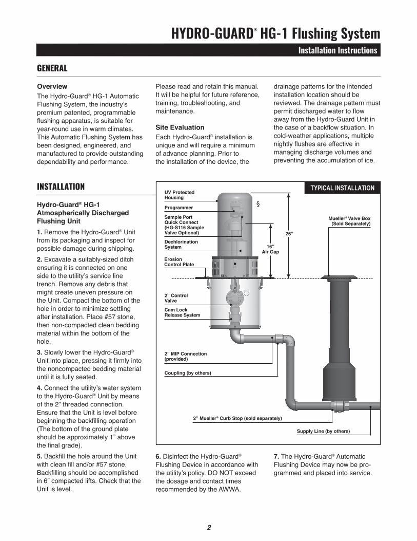
InstallatIon typical installation
Erosion control Plate
Sample PortQuick connect(HG-S116 SampleValve optional)
2” control Valve
coupling (by others)
26”
§
uV ProtectedHousing
Programmer
Dechlorination System
cam Lock Release System
2” MIP connection (provided)
16”Air Gap
Supply Line (by others)
2” Mueller® curb Stop (sold separately)
Mueller® Valve Box (Sold Separately)
hydro-guard® hg-1 Flushing SystemProgramming unit
2 3
• Rechargeable battery (low battery indicator shows both handheld and controller battery conditions) with recharging adaptor (9-volt lithium battery can be used in the built-in programming interface)
NOTE: In that the handheld was designed by its manufacturer to program flush systems, many displays use flush terminology. In the following instructions, in such cases the equivalent flushing terminology is shown in parentheses.
cAutIoN: Leaving the infra-red connector connected to the built-in programming interface can significantly reduce the battery life of the 9-volt batteries in the programming interface and the rechargeable battery in the tBoS-II handheld.
tBoS-II Handheld KeysHoME – press three seconds to turn handheld on.ABc – press to choose from three available programs (to store a program when preprogramming, or uploading a program to controller).LEFt and RIGHt ARRoWS – move curser left or right, also go back or forward one screen.oN and oFF/+ and – /uP and DoWN ARRoWS – Used to set flushing events on or off, move selector up and down on screen, or increase or decrease duration and other values.oK – press to make selection final.
Discharged water flushed from the Hydro-Guard® Unit should be routed away from the device into the surrounding environment. Proper preparation of the area around the device is essential. Use of sod or rock is recommended (See typical installation illustration on page 2).
technical Data • Operating temperature range of 32º to 120º F• Operating Pressure: 7 to 200psiNOTE: Where sustained pressures may exceed 120psi the installation of a pressure reducing valve (PRV) is recommended.
Battery Life• Will vary based on number of cycles per year, operating pressure, and temperature. We recommend checking the battery every 6 months, but in many cases, you will get more life out of them.
HG-1 (requires Handheld)tBoS-II Programming Instructions The TBOS-II handheld uses on screen prompts for intuitive programming. It will control current programming interface (T-2: dark gray case), as well as the previous model of programming interface (T-1 modules programmed by the TBOS-US handheld).Features• 1 to 24 possible flushing events
daily, or on selected days weekly, 365-day calendar
• Flush duration 1 minute to 12 hours (1 minute increments)
• Preprogram and store up to 3 different schedules
tBoS-II Handheld Home Screen Menu1. tBoS infra-red – accessible only
when connected to programming interface via the IR cable: select to connect handheld to programming interface via infrared cable and access programs on it, or to transfer programs from handheld to programming interface.
2. templates (tBoS-II) – select to program handheld without connecting to programming interface.
3. Settings – select to access and set time, date, and various other available user settings.
First time use1. Press HoME key for three
seconds to turn on handheld.2. Press RIGHt ARRoW key or the
oK key to access “Settings”3. Use DoWN ARRoW to select
and set the following:a) Date and Timeb) Contrast of the screenc) Name of the handheld controller
(can be assigned to a specific operator)
d) Language (English, French, Spanish, Italian, Dutch, Portuguese, Turkish, etc.)
ProGrammInG Hydro-Guard® unIt for oPeratIon
!
hydro-guard® hg-1 Flushing SystemProgramming unit
4
7. Use LEFt ARRoW to navigate back to the program “Settings” menu.
8. Select “Start times”, press oK to set.
9. Use ABc to select program to be set up.a) Set hours and minutes for each start time (up to 8 per program) using oN/oFF keys, press oK to set each (hours are indicated using 24 hour clock). [When exiting this screen, start times will automatically sort into chronological order.]
10.Use LEFt ARRoW to navigate back to the program “Settings” menu.a) Use DoWN ARRoW to select “Valve Run times” (Flush Duration), press oK to set.NOTE: Although six valves may be shown on screen, only Valve 1 is used to manage the Hydro-Guard® unit.b) Use oN/oFF keys to select program A, B and/or C (one or more can be assigned).c) Then use oN/oFF keys to set Flush duration (hours and/or minutes) for program just set, use LEFt/RIGHt ARRoW keys to move between hours and minutes and + and – keys to set times (1 minute to 12 hours), press oK to set.
transmitting time, Date and Programs to Programming Interface, clearing/checking Programs, Manual Start Connect handheld to programming interface using IR cable.1. To transmit: from home screen,
use DoWN ARRoW to select “tBoS-II infrared” and press oK. TBOS-II handheld will receive data (settings) from built-in programming interface.
2. Once data receipt is complete press RIGHt ARRoW to move to “Settings” menu.
Programming Flushing ScheduleThere are two ways to proceed: • select “tBoS-II infra-red” if IR
cable is connected to a TBOS-II programming interface to access, change or load programs there, or
• select “templates (tBoS-II)” to create or change programs stored on the handheld to load onto a programming interface at a later time (IR cable not used).
NOTE: The home screen for “TBOS-II infra-red” shows battery condition for programming inter- face and ON/OFF state of any current operation in progress.1. Press HoME key for three
seconds to turn handheld on.2. Press RIGHt ARRoW key or the
oK key to access “Settings”.3. Use DoWN ARRoW to select
“templates” and press oK.4. Use DoWN ARRoW to select
“Programs” and press oK.5. Use DoWN ARRoW to select
“Watering Days” (Days to Flush) and press oK.
6. Use uP/DoWN ARRoWS to select one of the following:a) custom cycle (Week): use RIGHt/LEFt ARRoWS to move to days of the week, use oN/oFF keys to highlight days on which to flush, then press oK to confirm days when selections are complete.b) Even Days: to Flush on even dates, press oK to set.c) odd Days: to Flush on odd dates including 31st, press oK to set.d) odd Days 31: to Flush on odd dated except 31st, press oK to set.e) cyclical: to Flush every “X” days, set “X” using oN/oFF keys (X=1 to 31), press oK to set; then set start date “dd/mm/yyyy” using oN/oFF keys, press oK to set.
3. From “tBoS-II infra-red” settings screen select “transmit” and press oK again. When program to be transmitted appears, press oK to confirm.
4. To clear programs A, B, or C: from ”tBoS-II infra-red” welcome screen, use DoWN ARRoW to select “clear Programs” and press oK, then select type of program to clear and follow prompts.
5. To check programs A, B, or C: from ”tBoS-II infra-red” welcome screen, use DoWN ARRoW to select “Programs” and press oK, then select what is to be checked and follow prompts.
Manual FlushingUsing TBOS-II handheld on the T-2 built-in programming interface (dark gray in color).NOTE: Manual start cannot be initiated if there is no program in the programming interface.1. To start manual flushing from
”tBoS-II infra-red” welcome screen.a) Use DoWN ARRoW to select “Manual Watering” (Manual Flush) and press oK,b) Select “Start Valve” (Open Control Valve) then using oN/oFF keys select “Valve 1” and press oK,c) Use oN/oFF keys to set the manual Flush Time (1 minute to 12 hours) and press oK to confirm. Flushing will start after a four (4) second delay.
Stop Manual Flush Sequence1. Reconnect IR cable to built-in
interface, then hold down HoME key on handheld.
2. Use RIGHt ARRoW to select “TBOS-II infra-red” menu and select “Manual Watering.”
3. Select “cancel Flush” to cease the manual flush sequence.
4
hydro-guard® hg-1 Flushing SystemProgramming unit
5
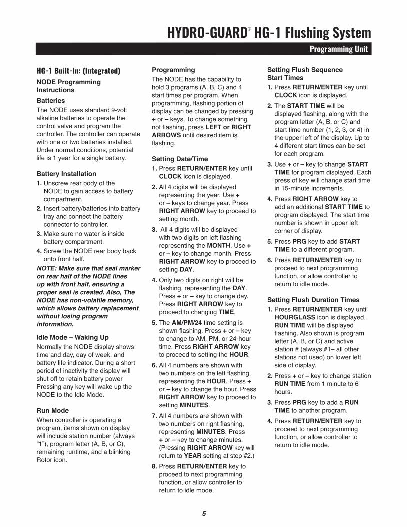
ProgrammingThe NODE has the capability to hold 3 programs (A, B, C) and 4 start times per program. When programming, flashing portion of display can be changed by pressing + or – keys. To change something not flashing, press LEFt or RIGHt ARRoWS until desired item is flashing.
Setting Date/time1. Press REtuRN/ENtER key until
cLocK icon is displayed.2. All 4 digits will be displayed
representing the year. Use + or – keys to change year. Press RIGHt ARRoW key to proceed to setting month.
3. All 4 digits will be displayed with two digits on left flashing representing the MoNtH. Use + or – key to change month. Press RIGHt ARRoW key to proceed to setting DAY.
4. Only two digits on right will be flashing, representing the DAY. Press + or – key to change day. Press RIGHt ARRoW key to proceed to changing tIME.
5. The AM/PM/24 time setting is shown flashing. Press + or – key to change to AM, PM, or 24-hour time. Press RIGHt ARRoW key to proceed to setting the HouR.
6. All 4 numbers are shown with two numbers on the left flashing, representing the HouR. Press + or – key to change the hour. Press RIGHt ARRoW key to proceed to setting MINutES.
7. All 4 numbers are shown with two numbers on right flashing, representing MINutES. Press + or – key to change minutes. (Pressing RIGHt ARRoW key will return to YEAR setting at step #2.)
8. Press REtuRN/ENtER key to proceed to next programming function, or allow controller to return to idle mode.
HG-1 Built-In: (Integrated)NoDE Programming InstructionsBatteriesThe NODE uses standard 9-volt alkaline batteries to operate the control valve and program the controller. The controller can operate with one or two batteries installed. Under normal conditions, potential life is 1 year for a single battery.
Battery Installation1. Unscrew rear body of the
NODE to gain access to battery compartment.
2. Insert battery/batteries into battery tray and connect the battery connector to controller.
3. Make sure no water is inside battery compartment.
4. Screw the NODE rear body back onto front half.
NOTE: Make sure that seal marker on rear half of the NODE lines up with front half, ensuring a proper seal is created. Also, The NODE has non-volatile memory, which allows battery replacement without losing program information.
Idle Mode – Waking upNormally the NODE display shows time and day, day of week, and battery life indicator. During a short period of inactivity the display will shut off to retain battery power Pressing any key will wake up the NODE to the Idle Mode.
Run ModeWhen controller is operating a program, items shown on display will include station number (always “1”), program letter (A, B, or C), remaining runtime, and a blinking Rotor icon.
Setting Flush Sequence Start times1. Press REtuRN/ENtER key until
cLocK icon is displayed.2. The StARt tIME will be
displayed flashing, along with the program letter (A, B, or C) and start time number (1, 2, 3, or 4) in the upper left of the display. Up to 4 different start times can be set for each program.
3. Use + or – key to change StARt tIME for program displayed. Each press of key will change start time in 15-minute increments.
4. Press RIGHt ARRoW key to add an additional StARt tIME to program displayed. The start time number is shown in upper left corner of display.
5. Press PRG key to add StARt tIME to a different program.
6. Press REtuRN/ENtER key to proceed to next programming function, or allow controller to return to idle mode.
Setting Flush Duration times1. Press REtuRN/ENtER key until
HouRGLASS icon is displayed. RuN tIME will be displayed flashing. Also shown is program letter (A, B, or C) and active station # (always #1– all other stations not used) on lower left side of display.
2. Press + or – key to change station RuN tIME from 1 minute to 6 hours.
3. Press PRG key to add a RuN tIME to another program.
4. Press REtuRN/ENtER key to proceed to next programming function, or allow controller to return to idle mode.
6
hydro-guard® hg-1 Flushing SystemProgramming unit
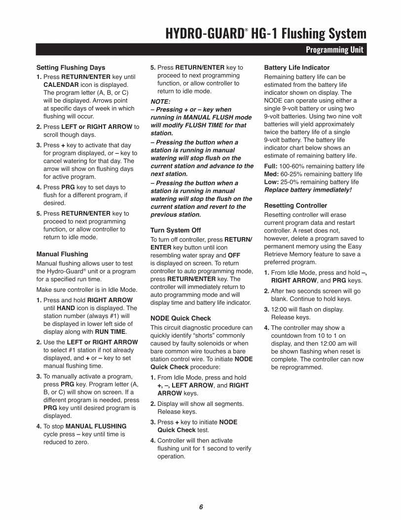
5. Press REtuRN/ENtER key to proceed to next programming function, or allow controller to return to idle mode.
NOTE:– Pressing + or – key when running in MANUAL FLUSH mode will modify FLUSH TIME for that station.– Pressing the button when a station is running in manual watering will stop flush on the current station and advance to the next station.– Pressing the button when a station is running in manual watering will stop the flush on the current station and revert to the previous station.
turn System offTo turn off controller, press REtuRN/ENtER key button until icon resembling water spray and oFF is displayed on screen. To return controller to auto programming mode, press REtuRN/ENtER key. The controller will immediately return to auto programming mode and will display time and battery life indicator.
NoDE Quick checkThis circuit diagnostic procedure can quickly identify “shorts” commonly caused by faulty solenoids or when bare common wire touches a bare station control wire. To initiate NoDE Quick check procedure:1. From Idle Mode, press and hold
+, –, LEFt ARRoW, and RIGHt ARRoW keys.
2. Display will show all segments. Release keys.
3. Press + key to initiate NoDE Quick check test.
4. Controller will then activate flushing unit for 1 second to verify operation.
Setting Flushing Days1. Press REtuRN/ENtER key until
cALENDAR icon is displayed. The program letter (A, B, or C) will be displayed. Arrows point at specific days of week in which flushing will occur.
2. Press LEFt or RIGHt ARRoW to scroll though days.
3. Press + key to activate that day for program displayed, or – key to cancel watering for that day. The arrow will show on flushing days for active program.
4. Press PRG key to set days to flush for a different program, if desired.
5. Press REtuRN/ENtER key to proceed to next programming function, or allow controller to return to idle mode.
Manual FlushingManual flushing allows user to test the Hydro-Guard® unit or a program for a specified run time.Make sure controller is in Idle Mode.1. Press and hold RIGHt ARRoW
until HAND icon is displayed. The station number (always #1) will be displayed in lower left side of display along with RuN tIME.
2. Use the LEFt or RIGHt ARRoW to select #1 station if not already displayed, and + or – key to set manual flushing time.
3. To manually activate a program, press PRG key. Program letter (A, B, or C) will show on screen. If a different program is needed, press PRG key until desired program is displayed.
4. To stop MANuAL FLuSHING cycle press – key until time is reduced to zero.
Battery Life IndicatorRemaining battery life can be estimated from the battery life indicator shown on display. The NODE can operate using either a single 9-volt battery or using two 9-volt batteries. Using two nine volt batteries will yield approximately twice the battery life of a single 9-volt battery. The battery life indicator chart below shows an estimate of remaining battery life.Full: 100-60% remaining battery lifeMed: 60-25% remaining battery lifeLow: 25-0% remaining battery lifeReplace battery immediately!
Resetting controllerResetting controller will erase current program data and restart controller. A reset does not, however, delete a program saved to permanent memory using the Easy Retrieve Memory feature to save a preferred program.1. From Idle Mode, press and hold –,
RIGHt ARRoW, and PRG keys.2. After two seconds screen will go
blank. Continue to hold keys.3. 12:00 will flash on display.
Release keys.4. The controller may show a
countdown from 10 to 1 on display, and then 12:00 am will be shown flashing when reset is complete. The controller can now be reprogrammed.
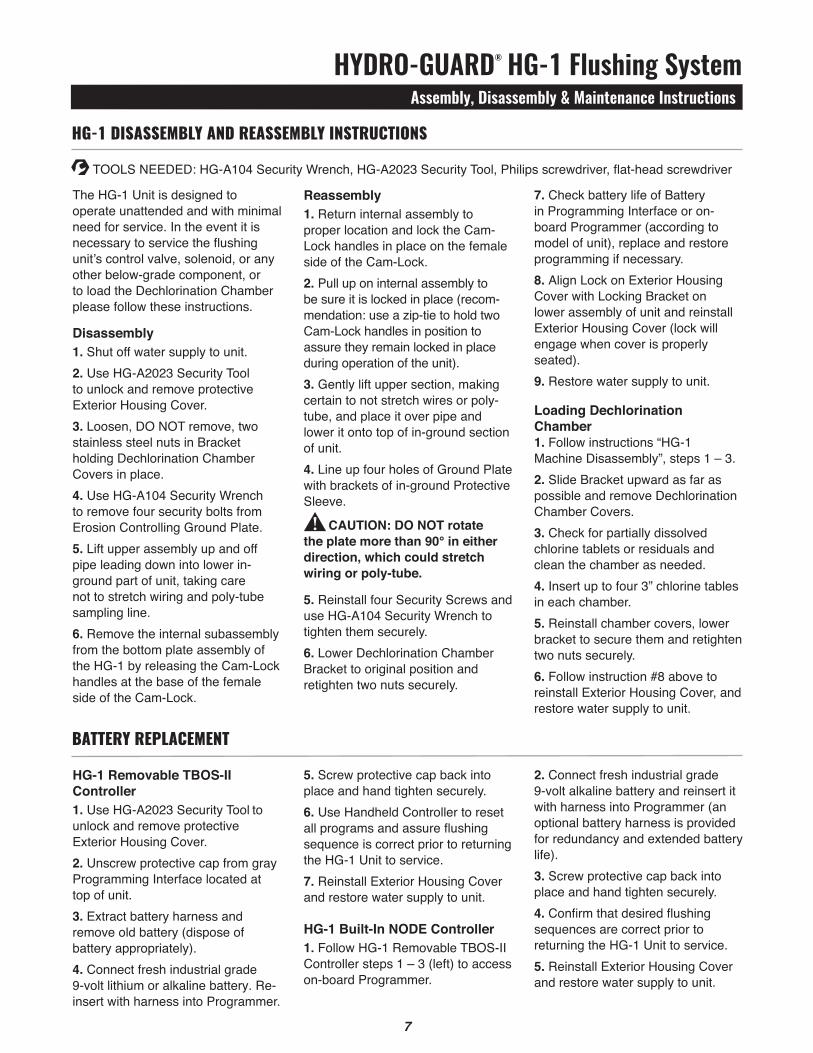
HG-1 dIsassemBly and reassemBly InstructIons
Reassembly1. Return internal assembly to proper location and lock the Cam-Lock handles in place on the female side of the Cam-Lock.2. Pull up on internal assembly to be sure it is locked in place (recom-mendation: use a zip-tie to hold two Cam-Lock handles in position to assure they remain locked in place during operation of the unit).3. Gently lift upper section, making certain to not stretch wires or poly-tube, and place it over pipe and lower it onto top of in-ground section of unit.4. Line up four holes of Ground Plate with brackets of in-ground Protective Sleeve.
cAutIoN: Do Not rotate the plate more than 90° in either direction, which could stretch wiring or poly-tube.
5. Reinstall four Security Screws and use HG-A104 Security Wrench to tighten them securely.6. Lower Dechlorination Chamber Bracket to original position and retighten two nuts securely.
hydro-guard® hg-1 Flushing Systemassembly, disassembly & Maintenance Instructions
7
The HG-1 Unit is designed to operate unattended and with minimal need for service. In the event it is necessary to service the flushing unit’s control valve, solenoid, or any other below-grade component, or to load the Dechlorination Chamber please follow these instructions.
Disassembly1. Shut off water supply to unit.2. Use HG-A2023 Security Tool to unlock and remove protective Exterior Housing Cover.3. Loosen, DO NOT remove, two stainless steel nuts in Bracket holding Dechlorination Chamber Covers in place.4. Use HG-A104 Security Wrench to remove four security bolts from Erosion Controlling Ground Plate.5. Lift upper assembly up and off pipe leading down into lower in-ground part of unit, taking care not to stretch wiring and poly-tube sampling line.6. Remove the internal subassembly from the bottom plate assembly of the HG-1 by releasing the Cam-Lock handles at the base of the female side of the Cam-Lock.
7. Check battery life of Battery in Programming Interface or on-board Programmer (according to model of unit), replace and restore programming if necessary.8. Align Lock on Exterior Housing Cover with Locking Bracket on lower assembly of unit and reinstall Exterior Housing Cover (lock will engage when cover is properly seated).9. Restore water supply to unit.
Loading Dechlorination chamber1. Follow instructions “HG-1 Machine Disassembly”, steps 1 – 3.2. Slide Bracket upward as far as possible and remove Dechlorination Chamber Covers.3. Check for partially dissolved chlorine tablets or residuals and clean the chamber as needed.4. Insert up to four 3” chlorine tables in each chamber.5. Reinstall chamber covers, lower bracket to secure them and retighten two nuts securely.6. Follow instruction #8 above to reinstall Exterior Housing Cover, and restore water supply to unit.
5. Screw protective cap back into place and hand tighten securely.6. Use Handheld Controller to reset all programs and assure flushing sequence is correct prior to returning the HG-1 Unit to service.7. Reinstall Exterior Housing Cover and restore water supply to unit.
HG-1 Built-In NoDE controller1. Follow HG-1 Removable TBOS-II Controller steps 1 – 3 (left) to access on-board Programmer.
HG-1 Removable tBoS-II controller1. Use HG-A2023 Security Tool to unlock and remove protective Exterior Housing Cover.2. Unscrew protective cap from gray Programming Interface located at top of unit.3. Extract battery harness and remove old battery (dispose of battery appropriately).4. Connect fresh industrial grade 9-volt lithium or alkaline battery. Re-insert with harness into Programmer.
2. Connect fresh industrial grade 9-volt alkaline battery and reinsert it with harness into Programmer (an optional battery harness is provided for redundancy and extended battery life).3. Screw protective cap back into place and hand tighten securely.4. Confirm that desired flushing sequences are correct prior to returning the HG-1 Unit to service.5. Reinstall Exterior Housing Cover and restore water supply to unit.
Battery rePlacement
!
TOOLS NEEDED: HG-A104 Security Wrench, HG-A2023 Security Tool, Philips screwdriver, flat-head screwdriver
8
hydro-guard® hg-1 Flushing SystemTroubleshooting
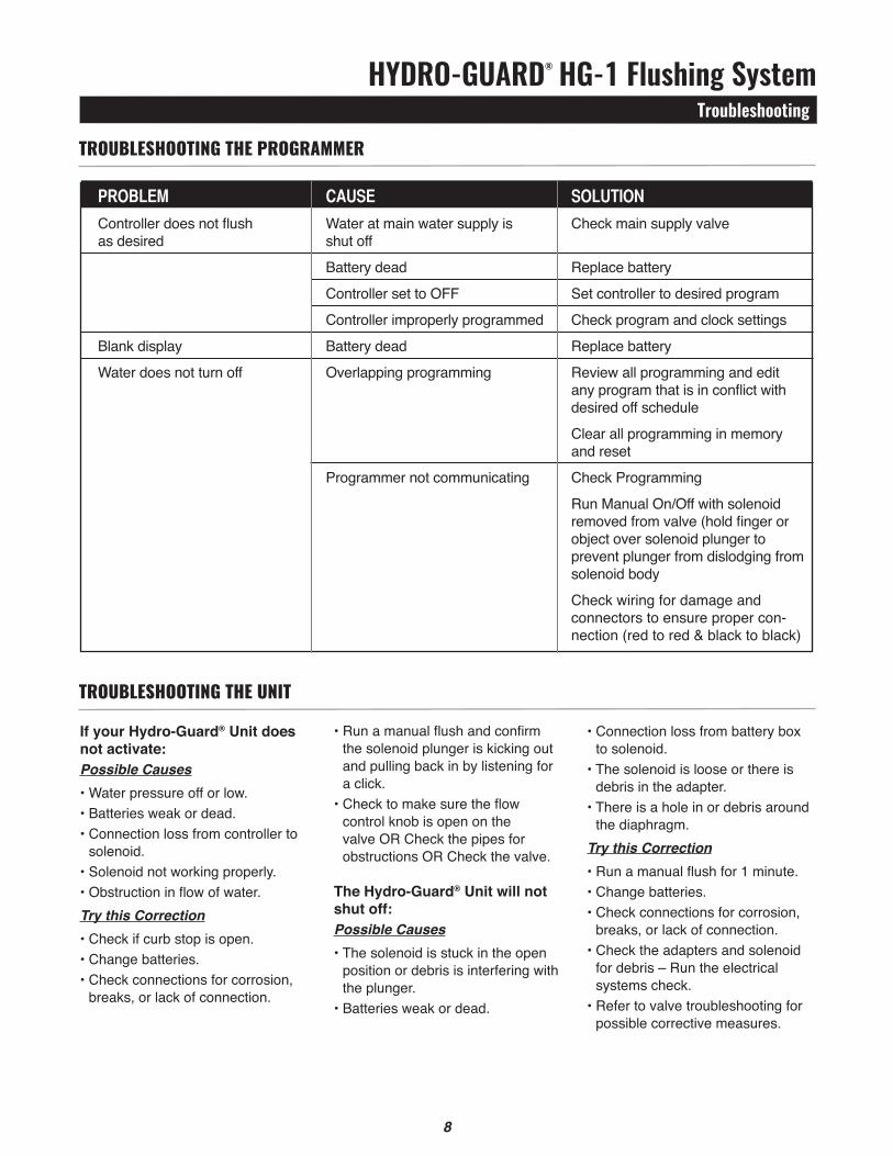
• Run a manual flush and confirm the solenoid plunger is kicking out and pulling back in by listening for a click.
• Check to make sure the flow control knob is open on the valve OR Check the pipes for obstructions OR Check the valve.
the Hydro-Guard® unit will not shut off:Possible Causes• The solenoid is stuck in the open
position or debris is interfering with the plunger.
• Batteries weak or dead.
If your Hydro-Guard® unit does not activate:Possible Causes• Water pressure off or low. • Batteries weak or dead.• Connection loss from controller to
solenoid.• Solenoid not working properly.• Obstruction in flow of water.Try this Correction• Check if curb stop is open.• Change batteries.• Check connections for corrosion,
breaks, or lack of connection.
• Connection loss from battery box to solenoid.
• The solenoid is loose or there is debris in the adapter.
• There is a hole in or debris around the diaphragm.
Try this Correction• Run a manual flush for 1 minute.• Change batteries.• Check connections for corrosion,
breaks, or lack of connection.• Check the adapters and solenoid
for debris – Run the electrical systems check.
• Refer to valve troubleshooting for possible corrective measures.
trouBlesHootInG tHe ProGrammer
pRoBlEM caUsE solUtion Controller does not flush Water at main water supply is Check main supply valve as desired shut off
Battery dead Replace battery
Controller set to OFF Set controller to desired program
Controller improperly programmed Check program and clock settings
Blank display Battery dead Replace battery
Water does not turn off Overlapping programming Review all programming and edit any program that is in conflict with desired off schedule
Clear all programming in memory and reset
Programmer not communicating Check Programming
Run Manual On/Off with solenoid removed from valve (hold finger or object over solenoid plunger to prevent plunger from dislodging from solenoid body
Check wiring for damage and connectors to ensure proper con- nection (red to red & black to black)
9
trouBlesHootInG tHe unIt
hydro-guard® hg-1 Flushing Systemoptions
9
protection, consider the HG-3 design. The HG-3 (18” to 108” bury) can be equipped with an optional patented freeze protection system that allows the water in the service piping to drain from the piping when a flush sequence is ceased.
S.M.A.R.t. Monitoring and Flush ManagementThe Hydro-Guard HG-1 can be upgraded to include a S.M.A.R.T. controller and a variety of water quality sensors. The S.M.A.R.T. equipped HG-1 will allow a utility to remotely monitor, in real-time, the water quality at a specific flush point
The following is a brief overview and introduction to Hydro-Guard® Options.
LoW LEAD BRASS INtERNAL coMPoNENtS AND PIPINGFreeze ProtectionThe Hydro-Guard® HG-1 Unit is freeze protected to 18” by virtue of the bury depth of the main 2” valve. The HG-1 offers a valve bury depth of approximately 16” with aboveground electronics that can be powered by a 9-volt Lithium battery (operational in temperatures as low as -20° F). For additional freeze
and automatically initiate a flush event when water quality conditions warrant.
the Hydro-Guard® S.M.A.R.t. flushing system:• Monitors chlorine levels (total or
free).• Flushes distribution line when
residual disinfectant drops below acceptable levels.
• Monitoring of pH, flow, temperature or turbidity available.
• Two-way real-time communication via cellular, wifi, ethernet or BlueTooth®.
Hydro-Guard® oPtIons and uPGrades
12 13
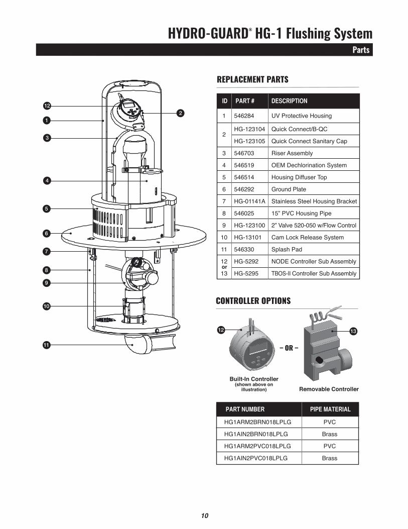
Built-In controller(shown above on
illustration) Removable controller
hydro-guard® hg-1 Flushing SystemParts
10 11
10
7
5
1
122
3
4
6
8
9
11
controller oPtIons
paRt nUMBER pipE MatERial
HG1ARM2BRN018LPLG PVC
HG1AIN2BRN018LPLG Brass
HG1ARM2PVC018LPLG PVC
HG1AIN2PVC018LPLG Brass
rePlacement Parts
iD paRt # DEscRiption
1 546284 UV Protective Housing
2 HG-123104 Quick Connect/B-QC
HG-123105 Quick Connect Sanitary Cap
3 546703 Riser Assembly
4 546519 OEM Dechlorination System
5 546514 Housing Diffuser Top
6 546292 Ground Plate
7 HG-01141A Stainless Steel Housing Bracket
8 546025 15” PVC Housing Pipe
9 HG-123100 2” Valve 520-050 w/Flow Control
10 HG-13101 Cam Lock Release System
11 546330 Splash Pad
12 HG-5292 NODE Controller Sub Assembly
13 HG-5295 TBOS-II Controller Sub Assembly
– or –
or

hydro-guard® hg-1 Flushing SystemNotes
11

Water (U.S.)[email protected]
Form 12769 - Rev 07/17
Copyright © 2017 Mueller Co., LLC. All Rights Reserved.The trademarks, logos and service marks displayed in this document herein are the property of Mueller Co., LLC, its affiliates or other third parties. Products marked with a section symbol ( § ) are subject to patents or patent applications. For details, visit www.mwppat.com. These products are intended for use in potable water applications. Please contact your Mueller Sales or Customer Service Representative concerning any other application(s).
Reliable ConnectionsTM
International1.423.490.9555www.mueller-international.cominternational@muellercompany.com