Embed Size (px)
Citation preview

0 >::c:
./
HYDRAULICS BRANCH OFFICIAL FILE COPY
UNITED STATES DEPARTMENT OF THE INTERIOR
BUREAU OF RECLAMATION
UREAU OF RECLAM!T.ON HYDRAULIC LAB~RATORY
r 1' r-rr ·Lt
1LE COPY E 1 BORROWED RETURN PROMPTLY
HYDRAULIC MODEL STUDIES OF THE FONTENELLE POWERPLANT DRAFT TUBE
AND TAILRACE SEEDSKADEE PROJECT, WYOMING
Report No. Hyd-571
Hydraulics Branch DIVISION OF RESEARCH
OFFICE OF CHIEF ENGINEER DENVER, COLORADO
August 1967

The information contained in this report may not be used in any publication, advertising, or other promotion in such a manner as to constitute an endorsement by the United States Government or the Bureau of Reclamation, either explicit or implicit, of any material, product, device, or process that may be referred to in the report.
Where approximate or nominal English units are used to express a value or range of values, the converted metric units in parentheses are also approximate or nominal. Where precise English units are used, the converted metric units are expressed as equally significant values.

CONTENTS
Page
Abstract . . . . . . . . . . . . . . . . . . . . . . . . . . . . . . . . . . . • . . . . . . . . . • . . iii Purpose . . . . . . . . . . . . . . . . . . . . . . . . . . . . . . . . . . . . . . . . . . . . . . . . 1 Conclusions . . . . . . . . . . . . . . . . . . . . . . . . . . . . . . . . . . . . . . . . . . . . . 1 Acknowledgment. . . . . . . . . . . . . . . . . . . . . . . . . . . . . . . . . . . . . . . . . 2 Introduction . . . . . . . . . . . . . . . . . . . . . . . . . . . . . . . . . . . . . . . . . . . . . 2 The Mod el . . . . . . . . . . . . . . . . . . . . . . . . . . . . . . . . . . . . . . . • . . . . . . 4 The Investigation . . . . . . . . . . . . . . . . . . . . . . . . . . . . . . . . . . . . . . . . 5
Flow Conditions in Unmodified Draft Tube . . . . . • . . . . • . . . . 5 Movement of Riprap . . . . . . . . . . • . . . . . . . . . . . . . . . . . • . . . . . . 6 Effect of Paving the Tailrace with 20-ton Slabs........... 7 Effect of Tri-vane Flow Splitter in Draft Tube
Cone . . . . . . . . . . . . . . . . . . . . . . . . . . . . . . . . . . . . . . . . . . . . . . . 7 Effect of Baffle Walls in Draft Tube. . . . . . • . . . . • . . . . • . . . . 8 Effect of Tri-vane Flow Splitter and Baffle
Walls in Draft Tube . . . . . . . . . . . . . . . . . . . . . . . . • . . • . • . . . . 9 Forces on Baffle Walls . . . . . . . . . . . . . • . . . • . . • . • . . • . • . . . . 10 Discharge Coefficients and Rating Curve . . • . • . . • . . . . . . . • 11 Summary of Tailrace Riprap Erosion Tests.... . . . • . . . . • . 12 Recommended Modifications . . . . . . . . . . . • . . • . . • . • . • • . . . . 13
Table
Dimensions of Important Features 1
Figure
Location Map . . . . . . . . . . . . . . . . . . . . . . . . . . . . . . . . . . . . . . . . . . . 1 General Plan of Dam and Sections . . . . . . . . . . . . . . . . . . . . . . . . . 2 General Plan and Section of Powerplant Area . . . . . . . • . • . . • . . 3 Repair of Outlet Works Stilling Basin . . . . . . . . . . . . . . • . . • . . . • 4 Erosion of Embankment . . . . . . . . . . . . . . . . . . . . . • . . . . • . . • . • . • 5 Air Vent . . . . . . . . . . . . . . . . . . . . . . . . . . . . . . . . . . . . . . . . . . . . . . . . 6 The Model . . . . . . . . . . . . . . . . . . . . . . . . . . . . . . . . . . . . . . . . . . . . . . 7 Wicket Gate Opening . . . . . . . . . . . . . . . . . . . . . . . . . . . . . . . . . . . . . 8 Tail water Curves . . . . . . . . . . . . . . . . . . . . . . . . . . . . . . . . . . . . . . . . 9 Model Riprap Gradation . . . . . . . . . . . . . . . . . . . • . • . . . • . . . • . . . • 10 Inception of Riprap Movement with Flow Splitters . . . . . . . . • . . 11 Neat Lines for Draft Tube . . . . . . . . . . . . . . . . . . . . . . . . . . • • . • . . 12 Dynamic Pressure Distribution on Baffle Wall . . . . . . . • • . • . . • 13 Pressure Factors for Differential Pressures on
Baffle Wall . . . . . . . . . . . . . . . . . . . . . . . . . . . . . . . . . . . . . . . . . . . . 14
i

CONTENTS- -Continued
Figure
Typical Measurements of Differential Pressure Across the Baffle . . . . . . . . . . . . . . . . . . . . . . . . . . . . . . . . . • . . 15
Discharge Coefficients . . . . . . . . . . . . . . . . . . . . . . . . . . . . . . • . . 16 Rating Curves . . . . . . . . . . . . . . . . . . . . . . . . . . . . . . . . . . . . . . . . . 17
ii
ABSTRACT
Hydraulic model studies of the draft tube at Fontenelle Powerplant show that erosive flow concentrations can be reduced through the use of either a tri-vane flow splitter in the draft tube throat or baffle walls in the draft tube flow passages when the unit is operated without a turbine runner. Both appurtenances are needed to allow diversion of 1700 cfs through the Fontenelle Powerplant during rehabilitation of the river outlet works stilling basin. The effect of flow splitter length orientation and vertical position in reducing flow concentrations is indicated. Baffle dimensions and distances above draft tube invert, as well as forces on the baffles are given. Provisional rating curves for the Fontenelle Powerplant are developed.
DESCRIPl'ORS-- *draft tubes/ *guide vanes/ *hydraulic models/ *velocity distribution/ *baffles/ discharge coefficients/ model tests/ turbine runners/ rehabilitation/ stilling basins/ erosion/ repairing/ diversion/ research and development IDENTIFIERS-- Fontenelle Powerplant, Wyo/ Wyoming
111

UNITED STATES DEPARTMENT OF THE INTERIOR
BUREAU OF RECLAMATION
Office of Chief Engineer Division of Research Hydraulics Branch Structures and Equipment
Report No. Hyd-571 Author: H. T. Falvey Checked and Reviewed by: W. E. Wagner Submitted by: H. M. Martin Section
August 1967
HYDRAULIC MODEL STUDIES OF FONTENELLE POWERPLANT DRAFT TUBE AND TAILRACE
SEEDSKADEE PROJECT, WYOMING
PURPOSE
This study was made to define and investigate hydraulic problems which could arise while the Fontenelle Powerplant is used for flow diversion and reservoir control during rehabilitation of the river outlet works stilling basin.
CONCLUSIONS
1. Placement of 20-ton concrete slabs over the tailrace riprap will not be effective in preventing erosion at a discharge of 1, 700 cfs (cubic feet per second).
2. The length, vertical position in the draft tube throat, and orientation of tri-va.ne flow splitters were important parameters in reducing flow concentrations in the draft tube. However, flow splitters alone will not prevent erosion of the tailrace at the maximum discharge of 1, 700 cfs.
3. Baffle walls placed in the right and center draft tube flow passages will be partially effective in reducing flow concentrations. However., the baffles alone will not prevent erosion of the tailrace with the maximum discharge of 1, 700 cfs. To prevent riprap from being drawn upstream into the draft tube, the bottom of the baffles must be placed 9 inches above the draft tube floor.
4. With the wicket gates open 100 percent, flow splitters combined with baffle walls will significantly reduce flow concentrations and prevent erosion of the tailrace riprap up to a discharge of 1, 700 cfs or a reservoir elevation of 6483. ·
5. The curves in Figure 13 are to be used in computing hydrodynamic forces on the baffles.
6. Provisional rating curves, Figure 1 7, were obtained to assist in estimating releases through the unit.
ACKNOWLEDGMENT
The recommended draft tube modifications were obtained through the combined efforts of the Structural and Architectural Branch, the Dams Branch, and the Hydraulic Machinery Branch, Division of Design; and the Hydraulics Branch, Division of Research. The Division of Engineering Geology was helpful in supplying topography and bedrock conditions of the tailrace. Photography was by W. M. Batts, M. P. Einert, and S. Rasmussen.
INTRODUCTION
Fontenelle Dam is the principal feature of the Seedskadee Project located in the Upper Green River Basin about 50 miles northwest of Rock Springs, Wyoming, Figure 1. The project is intended to provide irrigation water for about 60, 000 acres along the Green River.
The dam is an earth and gravel structure approximately 5, 000 feet long at the crest and rises about 127 feet above the riverbed. The principal hydraulic features are the spillway, the river outlet works, and the powerplant. The spillway is located in the right abutment of the dam. It is an uncontrolled, double side channel spillway with a crest length of about 300 feet designed for a maximum discharge of 20, 000 cfs. Flow from the spillway passes through a 400-foot-long diverging rectangular chute into a stilling basin. From the stilling basin, the flow passes through an excavated channel into the Green River.
The river outlet works, Figure 2, located near the center of the embankment is designed for a maximum discharge of 16, 400 cfs and includes an intake structure, a triple-barreled upstream conduit with 11-f oot-diameter water passages, a gate chamber, three 14-foot-diameter downstream conduits, a chute stilling basin and an outlet channel to the Green River. Three 8-foot 6-inch by 11-foot 0-inch fixed-wheel gates are situated in the gate chamber. Two 8-foot 6-inch by 11-foot 0-inch top seal radial gates control releases from the gate chamber through the left and center barrels. The right barrel of the downstream conduit contains a 10-footdiameter penstock which supplies both the powerplant and an 8-foot 6-inch square pressure gate at the upper end of the outlet works chute stilling basin.
The powerplant also located near the center of the embankment, Figure 3, consists of one generating unit which is capable of developing about 10. 0 megawatts under a 110-foot head. Flow for the powerplant passes through a length of 10-foot-diameter penstock, a surge tank, and into the spiral case of the turbine. After discharging through the turbine, draft tube, and tailrace, the water passes through a short reach of trapezoidal channel into the Green River.
2
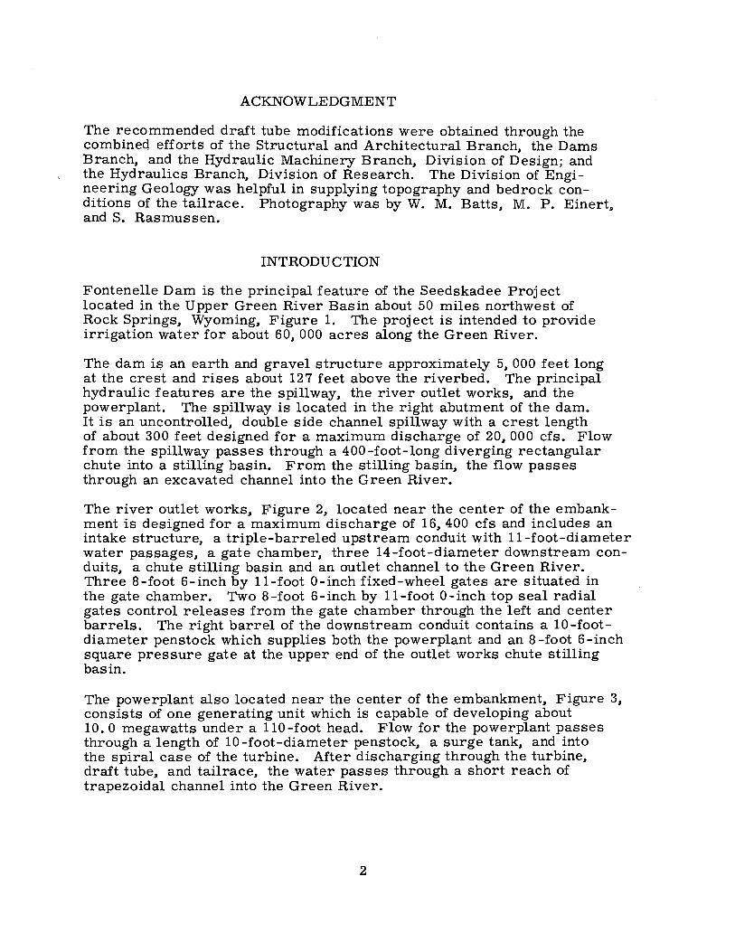
The problems encountered at Fontenelle Dam began with a multiple drowning in the reservoir. After an extensive search for the victims proved unsuccessful, the possibility arose that their bodies might have become entangled in the river outlet trash rack structure. The ref ore the river outlets were closed to permit an inspection of the trashracks by divers. This closing of the river outlets resulted in a rapid decrease in the downstream river elevation which in turn caused the saturated backfill near the left end of the outlet works stilling basin to slide into the outlet works channel and stilling basin. When releases through the outlet works were resumed, this material churned in the stilling basin and severely abraded the concrete surf aces and exposed reinforcing bars.
As soon as the extent of the damage was realized, a contract was let for cleaning and repair of the basin. Releases through the outlet works were again stopped and a cofferdam was constructed in the excavated channel downstream from the stilling basin. As unwatering of the basin began, a second backfill slide formed near the right end of the basin and depositing more material within the stilling basin.
As the cleaning process progressed, Figure 4, large upstream inflows filled the reservoir to within 2-1/2 feet of the maximum reservoir elevation. At the peak flow. as much as 10, 000 cf s were discharged over the spillway. This operation normally would not have caused concern; however, a large leak suddenly developed in the right dam abutment just to the left of the spillway. This leak was the result of water seeping through the bedrock underneath the earthfill and it caused considerable erosion of the downstream face of the dam. The erosion of the dam was so extensive that the safety of the structure appeared to be in jeopardy, Figure 5.
To quickly lower the reservoir elevation. releases were again made through the partially cleaned river outlet works. These releases flooded out the contractor's operations in the outlet works stilling basin and resulted in further abrasion of the already damaged concrete.
At the present time the reservoir is being kept at a low elevation by releases through the outlet works. The permeable bedrock under the right abutment has been sealed with a grout curtain and the downstream face of the dam has been repaired. However, before storage in the reservoir is resumed, the river outlet works stilling basin must be unwatered, thoroughly cleaned, and all damaged surfaces repaired.
During the period that the river outlet wo~ks stilling basin is being rehabilitated, required releases past the dam will be made through the powerplant. Studies on reservoir filling. conducted by the Dams Branch, indicated that the maximum diversion flow through the powerplant could be as high as 1, 700 cfs.
3

To provide as much capacity as possible and to insure that the flow is not stopped through an untimely mechanical breakdown of the untested running parts. the turbine runner will be removed. The turbine shaft will be replaced with a 10-foot-long, 2-foot 8-inch outside-diameter air vent pipe. The bottom of the air vent and the bottom of the wicket gates will be at the same elevation, Figure 6.
This study was made to provide information concerning flow conditions in the draft tube and tailrace at various discharges, reservoir elevations, and wicket gate openings when operating without the turbine runner. The information is needed to prevent damage to the powerplant tailrace and downstream channel during the diversion period.
THE MODEL
The model, built to a geometric scale of 1 :20 included an idealized spiral case, guide vanes, wicket gates, the air vent pipe, the draft tube, the tailrace, and a portion of the downstream river channel, Figure 7.
Since the model was originally intended for a basic research study concerning surges in draft tubes, a homologous representation of the flow passage from the penstock to the tailrace was not possible. The major deviations from the Fontenelle design were ( 1) the angle between the mod~l penstock and the tailrace was 90°. whereas the prototype penstock and tailrace are in line; (2) the model spiral case was rectangular in cross section, whereas the prototype spiral case is circular; however, the cross-sectional area in the model at each spiral case station was to scale; (3) for structural reasons, the model wicket gates were thicker than those in the prototype. In an attempt to partially compensate for the decreased flow area at a specific wicket gate opening, the height of the flow passage was increased from 3 2. 98 to 41. 76 inches (prototype dimensions).
The model wicket gates were adjustable to the extent that they could be set in three separate positions corresponding approximately to 19, 77, and 144 percent openings based on the open area of the prototype gates, Figure 8. Although the area of the gate opening in the model corresponded to the. prototype open area for a given percent opening, the width and angle of gate opening were not accurately represented because of the deviations listed in the preceding paragraph.
Tailwater elevations in the model were adjusted over a wide range with an adjustable tailgate located at the downstream end of the model. The tailwater elevation was measured on a staff gage located near the center of the channel about 1 foot upstream from the tailgate. This location corresponded to a station 100 feet downstream from the end of the draft tube. For a given discharge, the tailwater depth in the
4

model was adjusted to correspond approximately with Curve B of the Tailwater Rating Curve. Figure 9. Curve B was used since it produced the greatest tendency for erosion in the tailrace due to the lower tailwater elevation. Discharges in the model were measured with an orifice Venturi meter. The total upstream head on the spiral case was determined by adding the computed velocity head to the measured piezometric head at a station in the 6-inch supply line.
The floor of the tailrace section was made from concrete and conformed with the bedrock as determined from profiles measured in the field. The. prototype riprap was simulated in the model by 6. 5-mm (millimeter) gravel placed over the concrete. The model gravel was graded uniformly between 5. 0 and 6. 5 mm, with only 10 percent finer than 5. 0 mm. Figure 10. This gradation geometrically represented 4- to 5-inch riprap in the prototype. Although the gradation of the prototype riprap is not known, field reports indicate the size ranged between 1-1/2 and 5 inches.
Unless otherwise specified, all dimensions given in "The Investigation" section ref er to prototype dimensions.
THE INVESTIGATION
Preliminary observations of flow in the draft tube and tailrace revealed the presence of flow concentrations at the outlets of the draft tube which led to erosion of the tailrace riprap. Therefore. the major portion of the study was concerned with various draft tube modifications to reduce these flow concentrations. Means of protecting the tailrace riprap against erosion were also investigated.
Flow Conditions in Unmodified Draft Tube
The flow distribution at the end of the draft tube was influenced greatly by the swirl angle and the Reynolds number of the inlet flow. In general. the flow became more concentrated as either the swirl angle or the Reynolds number was increased. For these tests. the swirl angle was defined as the included angle between the axial and tangential velocity components of the inlet flow. Thus. the inlet swirl angle had a specific value for each gate opening which did not vary with discharge. The axial velocity component was assumed equal to the average inlet velocity, Q/ A. and the tangential velocity component was computed from the wicket gate opening and angle.
The flow concentration in the draft tube can be understood through consideration of the flow conditions in an elbow. With no inlet swirl, the flow in the elbow tends to form into two counterrotating spirals of equal strength. This tendency is commonly referred to as "secondary flow in an elbow." When the inlet flow enters the elbow at a small swirl angle, the spiral that rotates in tl;l.e same sense as the inlet swirl becomes stronger or more intense. Simultaneously the counterrotating
5

spiral becomes weaker. For large swirl angles and sufficiently high Reynolds numbers, the second or weaker spiral may even disappear. Thus, the effect of intensifying one of the counterrotating spirals through inlet swirl is to concentrate the high velocity flow in a relatively small cross-sectional area of the elbow. These same considerations are applicable to flow in a draft tube since a draft tube is essentially an elbow whose area increases in the downstream direction.
The dependence of the flow concentration on the swirl angle was confirmed qualitatively in the model. With the wicket gates open 144 percent, displacement of the 4- to 5-inch rocks in the tailrace began with a discharge of 815 cf s. This gate opening corresponded to a swirl angle of 45°48'. About 5 percent of the flow discharged through the left flow passage of the draft tube; a tendency existed for flow in the upstream direction in the center flow passage; and the remain-ing flow left the draft tube through the right flow passage.
With the wicket gates open 77 percent, 4- to 5-inch rocks in the tailrace began to be displaced with a discharge of about 710 cfs. This gate opening corresponded to an inlet swirl angle of 63°44'. Essentially all of the flow discharged through the right flow passage; a slight tendency existed, however, for upstream flow in the center passage and for downstream flow in the left passage of the draft tubes.
The 4- to 5-inch rocks in the tailrace began to be displaced with a discharge of 400 cfs when the wicket gates were open 19 percent. These conditions corresponded to an inlet swirl angle of 84°26'. All of the flow was concentrated in the right half of the right flow passage with upstream flow in both the center and left passages. The upstream flow can be attributed to the Venturi effect of the high velocities concentrated in the spiral flow which discharged through the right passage.
Movement of Riprap
The model showed that the bottom velocity required to move the prototype gravel was approximately 8 fps (feet per second). This value was estimated from velocity distributions in the tailrace as measured with a total head probe. This erosive bottom velocity as determined from the model was higher than the 5- to 6-fps bottom velocity predicted by other investigations. 1 / The ref ore, erosion in the prototype may begin at lower discharges than indicated by this report.
Operation at discharges larger than that required to displace the riprap resulted in extensive removal of riprap from the tailrace. This erosion occurred in the vicinity of the right training wall footing and was centered around Station e+30 (Figure 3). Due to excessive jointing in the bedrock and the risk of undermining the right training wall,
1/ Peterka, A. J., Hydraulic Design of Stilling Basins and Energy Dissipators, U.S. Bureau of Reclamation, Engineering Monograph No. 25, Figure 165.
6

operation at discharges larger than those required to displace the riprap is not recommended.
Effect of Paving the Tailrace with 20-ton Slabs
Because flow concentrations in the draft tube caused local movement of the tailrace riprap, consideration was given to some means of protecting the riprap against erosion. One scheme was to cover critical areas of the tailrace riprap with five 20-ton concrete slabs which had been ·, prepared to test the capacity of the powerplant crane and were available at the site. Several patterns of placement were tested in an effort to provide the greatest potential for protection. However, the tests show that for any placement, the slabs were displaced as much as 10 feet from their original positions in the tailrace with the gates open 144 percent and a discharge of 1, 700 cfs. This displacement was accompanied by excessive erosion of the underlying riprap. Therefore, attempts to place a protective cover over the tailrace ~iprap were abandoned.
Effect of Tri-vane Flow Splitter in Draft Tube Cone
Experience has shown that flow splitters in draft tube cones have been effective in attenuating draft tube surges. Part of this is undoubtedly due to the decrease in the magnitude of the swirl before the flow enters the elbow of the draft tube. By decreasing the inlet swirl, extreme flow concentrations at the draft tube exit are reduced. For this reason, a series of tests were conducted to determine the effectiveness of flow splitters in reducing the flow concentrations. This approach seemed desirable since it attacked the problem at its source.
Two separate flow splitters. each consisting of three straight vanes separated by 120°, were tested in the cone of the draft tube. One flow splitter was 2-1/2 feet long and the other was 5 feet long. Each flow splitter could be varied in orientation and height within the draft tube cone. The effectiveness of the splitters in reducing the flow concentrations in the draft tube was evaluated by observing the inception of gravel movement in the tailrace, Figure 11.
In general, the effectiveness of the flow splitter was dependent upon the area, the orientation, and vertical position of the flow splitter within the draft tube cone. The greatest reduction in the flow concentration was obtained with the 5-foot-long flow splitter placed so that the top of the splitter was even with the bottom of the wicket gates. The position represented the highest possible placement of the splitter because the air vent pipe extended down to the bottom of the wicket gates. The optimum orientation was with one vane pointing to the left at right angles to the horizontal axis of the draft tube.
Studies of flow splitters in various orientations yielded unexpected results. Preliminary tests with the spiral case indicated a very uniform
7

distribution of velocity in the draft tube cone. Therefore, one might expect that the orientation of the splitter vanes would have an insignificant effect on the flow distribution. However, the orientation was found to be decisive in establishing flow patterns within the draft tube. The effect of orientation on the flow conditions in the draft tube can be illustrated with the following example: With the wicket gates open 19 percent and one leg of the 2-1/2-foot-long flow splitter oriented upstream with respect to flow in the tailrace, a strong upstream flow existed in the left and center flow passages and a strong downstream flow was present in the right passage. By rotating the splitter to its optimum orientation, with one leg of the flow splitter at right angles to flow in the tailrace and pointing to the left side of the draft tube, downstream flow existed in both the left and right flow passages. However, the flow out the left passage was rather weak and some upstream flow still persisted along the floor of the passage. Strong upstream flow was present in the center passage.
Changing the overall elevation of the splitter also had a pronounced effect on the flow concentrations. With the splitter in its optimum orientation, raising the splitter improved the flow distribution, whereas lowering the splitter increased the flow concentrations.
The improved flow distribution in the draft tube and the increased loss across the flow splitter tended to raise the free surf ace of the flow within the draft tube. With either splitter, and for all gate openings, the water surf ace was in the vicinity of the top of the vanes. The extreme roughness of the water surf ace in the vortex and the spray at the top of the vanes increased the possibility of sealing the air vent pipe when the flow splitters were placed high in the draft tube cone. Although no adverse operating conditions were noted in the model with the highest placement of the flow splitters, undesirable operating conditions might exist at smaller gate openings than could be tested in the present model.~/
Effect of Baffle Walls in Draft Tube
Consideration was given to the possibility of forcing a redistribution of the flow in the draft tube through the placement of baffle walls in the areas of maximum flow concentration. Although this approach did not attack the problem at its source, it was felt that this means could reduce some of the adverse tendencies for erosion of the tailrace. Since the flow was concentrated on the right side of the tailrace, baffles
2/Spray and surging conditions in the air vent pipe with small gate openings were indicated in a letter to the Chief Engineer from Mitsubishi International Corporation dated April 6, 1966. Their recommendation was to extend the air vent pipe higher than the head cover on the turbine. The Japanese tests were performed without flow splitters.
8

were placed in the right and center flow passages of the draft tube upstream from the draft tube gate slot blockout1 Figure 12. This placement allows the draft tube gates to be closed and requires a minimum of unwatering during installation of the baffles in the prototype.
The baffles in the model were adjustable both in overall height and in distance from the draft tube invert. With the baffles placed on the draft tube floor1 riprap was drawn from the tailrace and deposited against the downstream face of the baffles. Since this riprap movement would tend to scour the draft tube and its agglomeration would prevent the draft tube gates from being closed1 this configuration was rejected.
The baffles were tested in successively higher positions above the draft tube invert until the flow under the baffles was sufficient to prevent upstream movement of the riprap. The optimum distance between the draft tube invert and the bottom of the baffles was about 9 inches. A higher position of the baffle resulted in large flow velocities under the baffle which eroded the tailrace.
With the wicket gates open 144 percent and a 2-foot 6-inch high baffle placed 9 inches above the draft tube floor1 the tailrace riprap started to move with a discharge of 11 530 cfs. At a 77 percent gate opening1
the riprap began eroding at 950 cfs. No riprap movement was observed for the 19. percent gate opening for discharges up to 520 cfs. For each of these g;:tte openings1 the flow appeared to be concentrated in the right flow passage with some flow out the left flow passage. A tendency for the deposition of riprap at the entrance of the center flow passage was noted.
Effect of Tri-vane Flow Splitter and Baffle Walls in Draft Tube
Neither the trj-vane flow splitter nor the baffle walls could individually reduce the draft tube flow concentrations sufficiently to pass 11 700 cfs without erosion of the tailrace. Therefore1 tests were conducted with both the flow splitters and baffle walls installed1 Figure 12. For these tests1 a tri-vane flow splitter 3 feet 6 inches long was employed. Physi-
. cal limitations in the prototype precluded the use of a longer flow splitter. The top of the flow splitter was placed approximately 3 feet 4 inches below the centerline of the distributor. Attachment problems in the field prevented a higher placement of the splitter vanes within the draft tube cone. The baffle walls were placed 1 foot 9 inches upstream from the gate slot blackouts in the right and center draft tube flow passages. The bottoms of the baffle walls were 9 inches above the invert of the draft tube1 and the wall height was 2 feet 6 inches.
With these appurtenances1 no movement of riprap in the tailrace was observed until the flow exceeded 11 975 cfs with the 144 percent gate
9

opening. Above 1, 97 5 cfs, a tendency for erosion existed near the downstream end of the left tailrace wall. Erosion at this location would not present a severe hazard even if the wall were undermined. There was no tendency for deposition of riprap at the end of the center flow passage for any gate opening.
To obtain a satisfactory distribution of flow with the baffle walls in the draft tube, the splitter vane orientation had to be changed from its previous optimum orientation. The new optimum orientation was with one vane placed at an angle of 7-1 /2° counterclockwise from the upstream direction, as seen from above. For this orientation there was no return flow into the left flow passage. With other orientations, some return flow on the floor of the left flow passage was observed.
Forces on Baffle Walls
Measurements of the :i:nstantaneous pressures on the baffle walls were performed to determine the loadings for which the walls must be designed. The tests were conducted with a 3-foot 6-inch long tri-vane flow splitter in the draft tube cone rotated to its optimum orientation. The baffle walls were 2 feet 6 inches high, extended across the width of the right and center draft tube flow passages, and were placed 9 inches above the draft tube floor. Preliminary tests were made with a piezometer located in both the upstream and downstream faces of a sheet metal baffle wall. To investigate the effect of a thicker wall, tests were made with a total of 13 piezometers distributed over all the flow surfaces of a 10-inch-thick wooden baffle wall. The more comprehensive measurements were made on the right baffle wall only, since this wall had the largest indicated pressure differential. The measured pressure differential across the sheet metal wall was approximately the same as that across the wooden wall.
A pressure concentration was noted near the center of the wooden wall in the horizontal plane and near the bottom of the wooden wall in the vertical plane, Figure 13. The total force on the wall was found to vary with both discharge and gate opening. Values of the vertical and horizontal pressure differentials across the wall for any gate opening and discharge can be obtained from the equation:
AP = KQ2 x 10-6 'Y
where A.; = the differential pressure on the wall (horizontal for either wall or vertical for the thicker wall), in feet
K = pressure factor from Figure 14
Q = total discharge through the draft tube, in cfs
10
(1)

The total differential force on the wall is computed from the equation:
F = 'Y • ap · A 'Y
(2)
where 'Y = the specific weight of water
A = the projected area in the direction for which the force is being computed
The values of K in Figure 14 are from the maximum pressure differentials obtained from an averaging circuit in the recording equipment. The instantaneous pressures exceed these average values by about 30 to 40 percent, Figure 15. The magnitude of the instantaneous pressures was probably attenuated for frequencies higher than 10 Hz in the model due to damping in the lines connecting the tap in the baffle wall with the pressure cell. These lines consisted of about 1 foot of 1/16-inch-inside-diameter brass tubing connected to about 3 feet of 1/4-inch Tygon tubing. Data are not presently available to estimate the amount of attenuation which occurs with this lead length configuration.
The application of Equations 1 and 2 is illustrated in the fallowing example:
Given: Wicket gate opening = 100 percent Reservoir elevation = 6485
Determine: The total horizontal force acting on a baffle wall
S0lution: The discharge for the given conditions as determined from Figure 17 is 1, 730 cfs. From Figure 14, a K value of 7. 5 is obtained. Substitution of the discharge and K values into Equation 1 gives a pressure differential across the wall of 22. 45 feet of water. This differential when substituted into Equation 2 results in a total force of 31, 515 pounds on a baffle wall whose area is 22. 5 square feet. Increasing this force by 40 percent would give the maximum horizontal force for which the wall should be designed. This value is 44, 120 pounds or 1, 960 psf (pounds per square foot).
Discharge Coefficients .and Rating Curve
To assist the designers and the project personnel in estimating releases through the unit with the turbine runner removed, rating curves for the unit were derived from discharge coefficients measured in the model.
11

The discharge coefficients, Figure 161 are defined by
Q=CAv'2gif
where Q = discharge, in cfs
C = discharge coefficient
A = area of wicket gate opening, in feet (Figure 8)
H = v2 /2g + P/-y = total energy at centerline of the distributor, in feet
The characteristic head, H, is defined as the total energy at the centerline of the distributor rather than as a differential head because the large quantities of air entering the vent maintain near atmospheric pressure on the downstream side of the wicket gates. Thus, for the unit operating without a runner, the tailwater elevation has no effect on the discharge through the unit. This premise was substantiated by tests with the wicket gates open 144 percent and a discharge of 1, 510 cfs. A tailwater vp.riation from elevation 6393 to elevation 6409 resulted in a 1 percent decrease in the discharge coefficient. This change in discharge coefficient is within the limits of experimental error and can therefore be disregarded.
The rating curves, Figure 17, were developed from the discharge coefficient curve in Figure 16. Since the discharge coefficient is based on the total energy at the entrance of the distributor, the energy loss between the distributor intake and the reservoir was added to the head at the distributor to obtain the reservoir elevation. For these computations, the energy loss was assumed equal to one velocity head in the 10-foot-diameter penstock.
The accuracy of these rating curves is questionable because of the deviations noted between the model and the prototype structure and because of the limited number of possible wicket gate positions. They can be used, however, for estimating releases through the unit.
Summary of Tailrace Riprap Erosion Tests
The discharges, in cfs, which were sufficient to start erosion of the tailrace riprap material are summarized in the following table: ·
12

Gate openmg (percent) 19 77 144
Unmodified draft tube 400 710 815 2-1 /2-foot tri-vane flow splitter
.,, 770 820 ..,..
5-foot tri-vane flow splitter .,, 1,080 1, 225 ..,..
2-1/2-foot baffles ,., 950 1, 530 ..,..
2-1/2-foot baffles plus 3-1/2-foot tri-vane flow splitter
,., * 1, 975 ..,..
*No erosion occurred for reservoir elevations up to 6470.
Recommended Modifications
To insure that discharges up to 1, 700 cfs can be diverted without eroding the tailrace channel, the combined use of baffle walls and a tri-vane flow splitter is recommended. The.baffles should be 2 feet 6 inches high and installed 9 inches above the floor in the right and center draft tube flow passages. In addition, they should be placed 1 foot 9 inches upstream from the draft tube gate slots. The flow splitter should be 3 feet 6 inches long and installed with its top about 3 feet 4 inches below the centerline of the distributor. It should be oriented with one vane rotated 7-1/2° counterclockwise from pointing upstream as viewed from above, Figure 12.
The erosion tendencies for various gate openings with•the recommended baffles and flow splitter is shown in Figure 1 7.
13

Table 1
Dimensions of Important Features
Feature
Height of dam Length of dam at crest Penstock diameter Air pipe. diameter Minimum draft tube diameter Maximum diversion flow
J:!.:ngl1sn umts
127 feet 300 feet 10 feet 2. 67 feet 10 feet 1. 700 cfs
1v1etr1c umts
39 meters 91 meters 3. 05 meters . 81 meter 3. 05 meters 48 cubic meters
per second

R.ll5oW. 114 II 112 110
u B
L
O IO
&µ1,.1 OF MILES
109 108
L E T T E
Ill ARMOR ROCK DEPOSITS ,. Sec. 21 f.29N., R.I00W. 2. SJc. 12 I 15 T. 29 11. , R. 100 W 3. Sec. II T. 29N., R. 104 W.
- ROCK SOURCES A~ and C.
102 101
T.24 N
IOAHO 23
22
21
20
,a
T.17N.
R.99W.
Atlantic City T. 29 tl
28
27
26
T.25 N.
: N28R.
@OENVER
RAD 0
KEY MAP
flNITEO STATES DEPl!RTMENT OF THe INTERIOR
Bl.IRE-AU Of' RECLAMATION
SEEQSICADl!E PROJECT-W'YOIIINII
FONTENELLE DAM LOCATION IIIIAP

" ~ :, \\\_s \ I ( ) \~,\-
~ ~,' ~ \ ~ -.....,_"-. ~ ?./ I
~ '
" c:;· ) Dom Sto 62+9/3~ Outlet Sta. 3+50 oo ~
0
8 ~
L Disposal area for stilling basin repair -
-------... \
\._ ·-- " N. II, 709. 52 ·.\ \ [. 17,502 90 .: Powerp/ont service road----· +-
'--Disposal area - --
Dom Sta. 30+22.91 i Outlet Sta. 30+0000 ~--
N 10,863. 57 -, -[. /4, 345.79 ) \
I
I
.-··Mox,mum W 5 El 6512 9
--_.,,_t:;..,' ~-- ---conservot,on W 5 [/. 6506
· · -lndctive W 5 El 6484 9
.-Dead W S / El 6408
•o SC
SCALE OF rEtT
, -3 I
100
- Src 62+5C.0C • Sta 59+50.00
· Disposal area
GENERAL PLAN 200 ,oo .,,.,
SCALE OF FEET
MAXIMUM SECTION
---~ 1,
800
PI.outlet Sto.23,-95_03':J ·
,.-·El. 6520.5
N. /1,46773 ?·· .. E.14,/83 91 )
LJ • 60'00' R• 20o' L • 209.44' r. 115. 47'
---Closure strucrure
f P.I. outlet Sta.!6+40.00 --~ N.11, 663. 41
'- E.IJ,453.64
Sta. 11+00.00--":
1J • 60'0o' R• 350' L • J66.5l_ T • 202.07
t<·--Sto. ts+oo.oo 1 I ,0 f-
~ . S."'0.0075------~ 1.o ~ ~ 0 0 - .s_-=OOC,_.'i5Q0==========---------------------------------------------------------------------.2:.=="---=-~ o.o 1.1..
CAMBE1R ON CREST OF DAM
6600 ---------
~-----.: River outlet works .: Spillway-------->J.. .. . " <f fest Crmcl outlet works ,,·Crest El. 6519 ........ ,:.
z ',! >-.. 6400 > ., .J
"'
~ l ~ _____ .,_,__ ' ---- GREEN
';~ j ,·3 I_..- --- ' ... J'. --Or,ginol ground surface ,-"Assumed firm foundation ______ '!,._ ___ ,;".'.:,:./50-"":1 Ji-r RIVER .,:._ -~·-
"'·· .: West Canal ~-- ''-' Trl'i'~: !::,,NI,-~ : --~tcap k--·.: Diversion 1l1l'l1i1!1i1 /
outlet works-· ' channel I I I
I Grout boles @ (l/flrox. to' crs - -- -1 --·
60 40 STATIONS 30 20
PROFILE ON£ OF CREST OF DAM
i Pl. Sta. /2+95.40 ·· -~ N.10,215.62 \
'- E.12,797. 41 )
( Dom Sto. l/+J0.72 __ --~ Outlet Sto. 5+32.00
; N.10,191.28 ,__ [. /2,634.54
I ~-y
' I
/ (Dom Sto.10+00.ao .._ __ _ : _ _j Access rood Sta. 6+90.00
, N.10,171.96 ~ E 12,505.25
--
10
-
FIGURE 2 REPORT H'!'0-571
- ··stockpile area for rip rap
CD ® ®
EMBANKMENT EXPLANATIOlf Selected cloy, silt, sand and grov.el compacted by 1'tlmt1Plf
rollers ta 6-inch layers
Selected sand, qrave.J and tobble1· c"0mpactedt,y crawl,r type tractor ti, tJ inch loyb'rs
Miscellaneous material compacted 'bj< ~/fl/Pi»g PO./ltH//i;lrl 12 - inch foyers.
/0-24-66 AS BUILT BY428, LETTER 8-!i-66 o- -5---?.H;
UNl'f~Q •·Y"ATEa
DEPARTMENT OF TM£ INT61IIO •.
BUREAU OF RECLAM~TI-ON
SEEOSlf,-QEf l'R~C.T-~
FONTENELLE DAM AND. POWER PLANT GE 116,lfAL. Pl.AN .ANSJ 418CT,_.

,,-El 6420.5 I _.--4" Gravel surfacing
""""===1-==s,..J'
SURGE TANK---• ,.__..___J
t f t I /J / • I /I
29-0---- --------------60-0----------- ----e2-o---
' ------35:0"------· ----25'-o"---Longif 'f. Unit.----
' f---+---------~--,-, .,,,<ce,-.;:-},i:~:Jc:---.-...-!i...lW1-U'L<3'4-'-Pt. Lateral 'f. Distributor El 6403.00-__. ..,,.
Sta. 32•1100
SECTION A-A
\Tl' 1-• 1209)-, -<,lR, I \ 1 , -, 5 25° W
\'f. Cable duct bank: __
1 ,.--Cham link fence /
.---E !. 64/3.0
GENERAL PLAN ',::,_-~, ·'' _, .• '--··---3'Ri,prap
--Coarse gravel-J'to 5 • ---Tai/race wall
6./-··,
20 0 zo 40 60
SCALE OF FEET
/
SW/TCHYARO
I I ;.;I I I y I
- - .... -- -,- -! '--TAIL RACE;
TRANSFORMER CIRCUIT
/
TOWER AREA,
~I I v I
/
/ /
.. -,._ -
0 :
I I I
--------~, .... :, ft:
------ -~ I I I I ,:.-;
FIGURE 3 REPORT HYD-571
h--~---~--~ IQ
J'Riprap--., /
IQ A:
<,,
k--'f. Tai/race channel
',·+ ' . "- -11-10, · - -/8. 0 .,.,
· ,Rt Tai/race wall · :, I
//,> .:....
SECTION C-C
Compacted perviaus backfill,
Power plant--,: I , _,,-El.6413.g,_/ .---El 6412.0
'~Assumed powerp/ont excavation line
SECTION B-B
NOTES
•• -Compacted. ,, embankment
: __ Sur~· of outlet r,1111{$
stilllng basin backfill
For details of catch basin, see {400). For Fontenelle Dam and Powerplanl General Plan and
Sections, see (210/. For lags of geologic exploration, see (209). For General Arrangements, see (172) thru (/74/. For details of surge tank, see (232/. For Switchyard General Pion, see (414 ). For details of tailroce walls, see (/79/ and (439/.
12-2- 64 REVISED TAILRACE SLOPE~ TRANSFORIIERS, GENERATOR
D. A.J.P. AND MINOR CORRECTIONS. 4- 26 -6J TRACED. REV. BUILDING FOUNDATION, TAILRACE WALLS,
0. A.J.P. SERVICE AREA, DRAIN DITCH, AND SWITCHYARQ,
AUIIAYS TNlftK SAfETV I.INIT£D STATES
DEPARTMENT OF TH£ INTERIOR
BUREAU OF R£CL AMAT/ON
SC£0SKAOEE PROJCCT- WYOM/NO
FONTENELLE POWER PLANT GENERAL Pl.AN A,,. SECTION
OF POWER PLANt' AREA

Removal of remaining pervious backfill on west side of river outlet works stilling basin - August 20, 1965.
--.:.-- GATE STR UCTURE ~
Excavation of river outlet works backfill slide material - September 3, 1965.
FONTENELLE DRAFT TUBE STUDY
Repair of River Outlet Works Stilling Basin
Figure 4 Report Hyd-571

t:rl 'i 0 Ul I-'• 0 ::i 0 H,
t:rl a O" Pl ~ :,;-a (I)
~ .-+
>:rj 0 z >-3 t:rl z t:rl t"' t"' t:rl 0 ::0 :i> >:rj >-3 >-3 C: o::J t:rl en >-3 C: 0 Kl
Fontenelle Dam, Seedskadee Project, Wyoming . Aerial view of slide cavity in downstream face of dam. Abutment rock is exposed at lower left side of cavity. Riprap material was dumped from top of dam. September 5, 1965.

SECTION A-A
/- Tac!< weld .screen tol'lat:1/1'3 '1/fer I venr p1p4 has been l',rtad t,;, I head cover. I
P-ART /IKl. I
a 3 4 s
Ll ST Of' MATUHAlS Of.SC~Rti-ON
:tz,f'o,.i:x~ _.: i4£F+4iii:llnlrs• f.070" Ieng .
.,f,."Di<:1'.l! ,. ... ~- a- ring Tt' d·"-" 9'-,<>." bar. lt"oX':t,~.,I(. '3,-t'); t/lfr .
40¼" on.." 3Zt lO.,. ¾ th ic:I\ d119 ' t"-~··FJC • ri .. Cape.craws
i-"-13-111(;:,>.1 ::t • bolts lfsf t 3'·2"t>or
FIGURE 6 REPORT HY0-~71
MAi£RIA st«"''
rubber &~•.I •.teeJ
/-Woven wire space screen wifh/-1
·, /"spaces and wire dio.. 0./35" \I __ ;
I I
,l -
6 7 a 9
10 II
12 4 4 4 I I
f -13 NC i I~ oai:>screw i"•:f'.~ 9'-o". bar 4 1.-tai•_..(.:4-1
... 0". Wovr,n wire space sor .... er, with. /":,paces anr;J w;~., dia. 0.135''
II~ edr•·•l 9~1 steel ~~,
si-"81 st•el
I
l .. .,!.-j---
- A -- ---~E:_~L- ~ - - ·- :/"==· i#-1~~~==;e,=l'=-'=-"=-="-"'-="-~?ee'Jse:..";;,;?,,,,~s-~= I Drill holes in venf- p,pe o.nd bolf, "--oetail B : braces in place after vent ppe ! has Deen ins to! led /n I head cover. -I .~,
'~
~ Shop dri JI t "dia. [ ; hoies In br"aces --; __: _ --- -
I I I
t- ---1 I
' I
0 3jl"LO. pipe. (_;f wall thickness-)
ve11f p,pe.
i5': i ' / '
.-:Jleel r;,-,.J:
· - 32.5:JO tvfa x.
r
l' 4
__ i ____ ·--. - -·-- - - -- -- -- _lL..-------"-------.....11
TR,ANSVERS£ SECTION
~ r-// t
jjJ @_: DETAIL B
....,, ,.. 1" ~12 x 2 bar, 4braces equally
space::1 qround vent pipe. L ocafe m neid.
(!z'·, // Replace w/th '·=--' / blind (10119es - -<:
;;-Pt:~vide /.1!·/'.8NC ' x !J Capscrevv.s
~)
,~;f-13/1/C .rf capscrew ('91 <__,/
,-- ,'loin bttOl';,,9 Slf/JPtUt Hl'gr. Owg, ~ 3S·,UIJ3'8
'
,- IIHd co.-er lfl'Q,-: o..,g. No. SS'·ii.,2.rl! A I
'
I ,
/
/ /
12 12 9"0.D Clo$i; /ZS Plain cast iron bJind &-Jonqe f·':Jcecland dri'll,tcJ
··· -Each o." fhe. 6 baku,ca pipes. when discor,nec-ted lor removal of the heDd caver, should be ()locked with blind rlan9es of the pit liner andar the disconr,ected end of fh,s balance pipe inf-he rurbJne pit' durin:j rhe period of river diversion through the turb1r>e.
The act-uaf-in9 mechan/sm al the auf-on1atic air valve should remain disconnecf-ed and f/?e valve ,ixed in the closed po:s!-hon during the period of river diversion through rhe rurbine.
NO TES
cost 11"'0n
/ 5ervomorors, opera t,ng ring and gar~ linkage. nor shown.
c. Hi,r, l;'WS. El. 6392.00 -~n .. , l /lfaJ<. T.W.S. El. 6~04'.-I (Flcoti ,to9ej7
,~ E DLstriJ;,.utw' ( El. H01flQ
_{. ______ _
0 I '--.....___._...___._ ___ __j
SCALt OF FEET
R£FEliENCt DRAWlN(;S.
Hydra;,./,< T.,rt,in£ Secf-io.na/ . A,.s.,,,bly _ _ .. _____ -· ___ IS-#-•lJ·HII
ALWAYS TillnK SAfETV tJNIT£0 STATE$
~PARTMDYT QF THI! INTl!lf10R 8URl!AU OF Rl!Ct.AMAf'ION
S1!6D$/CADEE. PJI-Q.J£~1'·WYOH.1Nd
FONTENELL£ POWER PLANT A,flf· V€'NT
T/JRBINF HO!)lrJCATJOJJ FOR R.WE.R a}Jti;. SiON

View of unmodified model from downstream.
Plan view of modified model.
FONTENELLE DRAFT TUBE STUDY
The Model 1:20 Scale Model
Figure 7 Report Hyd-571

w Q..
80
70
>- 60 l-o l-o It: Q..
~ 50 u.. (/)
w I<(
<!> 40 1-w ::.::: (.)
~ u.. 30 0 <( w It: <(
Z 20 w CL. 0
10
~ /
V W""
20
• Prototype measurements 0 Model measurements
,II , /
)
V /
/ /
/ /'
/ If
/ r
40 60 80 100
GATE OPENING (%)
FONTENELLE DRAFT TUBE STUDY WICKET GATE OPENING
I: 20 SCALE MODEL
FIGURE 8 REPORT HV0-571
~ , /
/ .~ /
~' /'
,/
120 140

FIGURE 9 REPORT HYD-571
6402 • Observed water surface ,,,,,,,. ,,,,,-
elevations. _JI' ~
6400
Curve A- Computed ~ - ,,__. by Region.--- ~
~ ~
;,,,,, ... ' .,,, .,
~ ~
j .,,, I...,. ~ ....
i-: LL
6398 z 0 I-<I > lu ....J 6396 lu
a:: lu I-<I 3
6394
~ ,,, ~ ~ ~ /
V J/ V /
V ~/ , ,
I V ~~ ... _ -- - 1-Curve a-Revised
J • curve to include V degradation. l/ ....J
.:! .I I
6392 ) ,
10 15
DISCHARGE (1000 cfs)
FONTENELLE DRAFT TUBE STUDY TAIL WATER CURVES
I: 20 SCALE MODEL
20 25

100
90
iO
<!) 70 z (/)
60 (/) <{ fl..
I-50
z w 0 40 Q: w a... 30
20
10
0
U.S. STANDARD SERIES "*100 •10 ~ *3o •1s •10*8
I
I
I I I I
I :
:
1 I Range of grovel
FIGURE 10 REPORT HYO- 571
CLEAR SQUARE OPENING .-4 s,41" 5/4" 1V2" s"
•••--•r" -
--
- sizes in prototype ~
I Ya" to 51 . /Groin size distribution=:
I " used in model I I I •
I I
.,
DIAMETER OF PARTICLE IN MILLIMETERS
FONTENELLE DRAFT TUBE STUDY MODEL RI PAAP GRADATION
1:20 SCALE MODEL
O O 0 ct ••

FIGURE 11 REPORT HYO - 571
110
100
8) -Tallrac,
RDr '
80 Q~rac, r:i ~10 J: <J
DEFINITION SKETCH 0 <(
ILi 60 ~·1
J:
...J <[
I-z ILi a:: ILi IL IL
0
50
19% Gate
40
\ \
Bottom of air vent pipe
201-----+----+-----l~-·==-~1---+---+----+-------i,----~ \ \ 144%
Gate
101-----1--------1-------l,-----4------+-----+---------
o.__ ___ .__ __ ___....._ __ ---1, ___ ___._ ___ _._ ___ ....._ ___ ...._ __ ___,
0 200 400 600 800 1000 1200
DISCHARGE [ftYSEC.J
FONT EN ELLE DRAFT TUBE STUDY INCEPTION OF RIPRAP MOVEMENT
WITH FLOW SPLITTERS
I: 20 SCALE MODEL
1400 1600

00 I
auD
A
14 LO"
27L43" >- O
/1//Y>tc >;'<--3 4 i u
rn 0
0 0
12" R
/5'4"
/1' 7" -0
a O O O
O O
A A
7
Fl -73
—0
\
00 N0
R3 •
01
I
NFQ
9L,in
N, • NI
- 917 "
0
I e Y _ • /0'3"
10'-6
•--Line of tangents to fillets----_
9 114
12" R
-e -o
6 L
9 ,7g'
/0 -(11)
—0 /3157"
4'4"-
012"R
idV
I:1 0
40
3 N
O N
O/1
.93
S
SO
L.1
6£
9
13-
„E,ii
=„6
7E @
sao
ods
£
NET AREA-SQUARE FEET
4.0 0 0 O O 0 ▪ 0
Tota
l cro
ss se
ctio
na
l are
a
along 1
of d
raft tu
be
r
1— I
r \
F—
r
HVeloc
ity fo
r 61=
1,700 cfs
.
r
1—
r
r
L
VELOCITY-FEET PER SECOND
_Y__
co
'Co
0'10
1 re
'!.141
of
a t
`1, aT i 00
1 3! i r, AC
a
S3
A2I
1 73 A
110073
A O
NV
V3, 1
1V
5'.
a 6J
og9si
p J
o'
e5
DE
VE
LO
PE
D H
AL
F P
LA
N O
N €
OF
DR
AF
T T
UB
E
Ns
---
0
o 1 off' i
0
••1 1%1 I
.0
13
33
30
31V
3S
310 9L11"
O
4 k" ›-
00 -
rt
L< 91/1" >4< 3".- -4' /
-®
171.10 -f" „1
E5'" -15
\N 3 ,11"--- --4L5y -0
0
i 0
O
p
o
5- -P 5!-//i" 0:- o
L 5 41"\-;
.‘.55 =r7' I "
1)
7'/0e---
L
3 L 5 "
-A-
0
\ 3
Or
0 O
PLAN
ELEVATION
Maximum Pressure
FIGURE 13 REPORT HYD-571
Note= Pressure intensity direction arrows ore drawn at location of piezometers
Scale of Pressure Intensity, in feet of water.
SECTION THROUGH CENTERLINE
FONTENELLE DRAFT TUBE STUDY DYNAMIC PRESSURE DISTRIBUTION
ON BAFFLE WALL
Q = 547 CFS GATE OPENING= 19%
I: 20 SCALE MODEL

FIGURE 14 "EPORT HYD-571
25
\ Jf"" Diffartntlal Pressure Intensity acron the Baff It, In feet. 'f' 20
)0 0 ,Q.. )( ~N "'
Q .. Totol Diachorgt through Draft Tube, In cubic feet per second.
0 II
:lll:: 15
0: 0 t-o : ~ 0: :::::, (/) (/)
w 0: 0..
10
-
~~
~ r--.....
........
~-..... Horizontal force
,,,. ....... ,, i-Downpull force I'--.... ..........._
I -........... r---,...... I t r---
20 50 60 80 100
PERCENT GATE OPENING
FONTENELLE DRAFi TUBE STUDY PRESSURE FACTORS FOR
DIFFERENTIAL PRESSURES ON BAFFLE WALL
I: 20 SCALE MODEL
120
.....
~
--
140

(/1.,'\
RIGHT BAFFLE
FIGURE 15 REPORT HYO -571
AVERAGE INSTANTANEOUS
Q :r 1839 CFS
RIGHT BAFFLE
CENTER BAFFLE
AVERAGE INSTANTANEOUS
Q = 1304 CFS
FONTENELLE DRAFT TUBE STUDY TYPICAL MEASUREMENTS OF DIFFERENTIAL
PRESSURE ACROSS THE BAFFLE
GATE OPEN I NG = 144%
I: 20 SCALE MODEL

FIGURE 16 REPORT HYD-571
'·
~ 0
~B C
II
a t-!" z .6
"' i3 I.L I.L
"' 0 0 .4
"" (!) 0: ct J: 0 en .2 0
\
"' I"' ~ ' ' ~ ......._._,_
i-,..,.__
----r---' Q• Total discharge through draft tube, in cubic
feet per second. A= Area of wicket gate opening, In square feet. ~ p .
H = 29 + T = Total energy head on penstock center
llne at entrance of scroll case, in feet. __ T ___ ---T-- --- -r-·-·r---~----T-· 20 40 60 80 100
PERCENT GATE OPENING
FONTENELLE DRAFT TUBE STUDY DISCHARGE COEFFICIENTS
POWERPLANT DIVERSION FLOW
I : 20 SCALE MODEL
r--. r--....... -
120 140

z 0
I-ci > w ...J w Q:: -0 > a:: w (/)
w a::
6520
6510
6500
6490
6480
6470
6460
6450
6440
6430 0
/ I
~ 0 0 (\j
h,NO erosion
j
I I I
j I I I I
FIGURE 17 REPORT HYD-571
\ El. 6506.0 Spi I I way Crest \ I I I I
\ I I J \ .
-L--u -_f-' l_ ~
--' I I I
\ I I I r\.
"' I ,
j
fl 't q Q
* I ~ 11 0 'if' Q) /
I I ( I /J
"- Erosion of tail race n1 J J riprop begins with ,~ I I I recommended baffles and guide vanes.
I I I I I / j
I
j I I I I I I I I JI
/J I /J I
1000 2000
Q (cfs)
FONTENELLE DRAFT TUBE STUDY RATING CURVES
POWERPLANT DIVERSION FLOW
I: 20 SCALE MODEL
GPO 837-022

7•1750 (2-67) Buraau ,,, Reclamatloa
CONVERSION FACTORS--BRITISH TO METRIC UNITS OF MEASUREMENT
The following conversion factors adopted by the Bureau of Reclamation are those published by the American Society for Testing and Materials (ASTM Metric Practice Guide, January 1964) except that additional. factors(*) commonly used in the Bureau have been added. Further discussion of definitions of quantities and units is given on pages 10-11 of the ASTM Metric Practice Guide.
The metric units and conversion factors adopted by the ASTM are based on the "International. System of Units" (<lesignated SI for Systeme International. d'Unites), fixed by the International. Committee for Weights IIJ].d Measures; this system is also known as the Giorgi or MKSA (meter-kilogram (mass)-second-ampere) system. This system has been adopted by the International. Organization for Standardization in ISO Reco=endation R-31.
The metric technical unit of force is the kilogram-force; this is the force which, when applied to a body having a mass of 1 kg, gives it an acceleration of 9. 80665 m,/sec/sec, the standard acceleration of free fall toward the earth's center for sea level at 45 deg latitude. The metric unit of force in SI units is the newton (N), which is defined as that force which, when applied to a body having a mass of 1 kg, gives it an acceleration of 1 m,/sec/sec. These units must be distinguished from the (inconstant) local weight of a body having a mass of 1 kg; that is, the weight of a body is that force with which a body is attracted to the earth and is equal to the mass of a body multiplied by the acceleration due to gravity. However, because it is general practice to use "pound" rather than the technically correct term "pound-force," the term "kilogramll (or derived mass unit) has been used in this guide instead of "kilogramforce" in expressing the conversion factors for forces. The newton unit of force will find increasing use, and is essenilal in SI units.
Mil. Inches
Feet.
Multiply
Yards •... Miles (statute).
Square inches • Square feet •
Square yards Acres ••
Square miles
Cubic inches Cubic feet. Cubic yards •
Fluid ounces CU. S. )
Liquid pints cu. s.)
Quarts CU. S. ) •
Gallons CU. S. i:
Gallons (U. K. i Cubic feet .• Cubic yards. Acre-feet ••
Table I
QUANTITIES AND UNITS OF SPACE
By
LENGTH
25.. 4 (exactly). 25. 4 (exactly) •.
2. 54 (exactly)*. 30. 48 (exactly) • • • •
0. 3048 (exactly)* ••. O. 0003048 (exactly)* • O. 9144 (exactly) • .
1,609.344 (exactly)* : • 1. 609344 (exactly) •
AREA
6. 4516 (exactly) • 929.03* .•••••
0.092903. o. 836127 . 0.40469* •
4,046. 9* ; 0. 0040469* • 2.58999 ••
VOLUME
16.3871 •• 0.0283168. 0. 764555 •
CAPACITY
29.5737 • 29.5729 •• 0,473179 . 0.473166.
946. 358* •• 0. 946331*.
3,785. 43* 3. 78543. 3. 78533. o. 00378543*. 4.54609 4.54596
28.3160 • 764.55*
1,233. 5* • .1,233,500*
To obtain
Micron Millimeters Centimeters Centimeters Meters Kilometers Meters Meters Kilometers
Square centimeters Square centimeters Square meters Square meters Hectares Square meters Square kilometers Square kilometers
Cubic centimeters Cubic meters Cubic meters
Cubic centimeters Milliliters Cubic decimeters Liters Cubic centimeters Liters Cubic centimeters Cubic decimeters Liters Cubic meters Cubic decimeters Liters Liters Liters Cubic meters Liters

MultiplY
Grains (1/7, 000 lb) , • • Troy ounces (480 qrains). Ounces (avdp), • • • Pounds (avdp) •••• Short tons CZ, 000 lb).
Lonq tons (2. 240 lb) ;
Pounds per square ·inch
Pounds per square foot
Ounces per cubic inch • • • Pounds per cubic foot • • •
Tons Oonql per cubic ya1'I :
Ounces per gallon CU. S.) Ounces per gallon (U, K.) Pounds per gallon (U.S.) Pounds per gallon (U, K, l
Inch-pounds
Foot-pounds
Foot-pounds -pa.; irich Qunce•inchsS • I
Feet per second.
Feet per year. : Miles per hour •
Feet per second2 •
Cubic feet per second (second-feet) ••••••..•.•
Cubic feet per minute • • • Gallons (U. B. l per minute •
Pounds.
By
MASS
64. 79891 (e:xactly) • 31.1035 •••••• 28.3495 .••••••
O. 45359237 (e:xactly). 907.186 •••••
. o. 907185 •••• • 1.016.05 ••••••
FORCE/AREA
0.070307. o. 689476. 4.88243 •
47.8803 ••
MASS/VOLUME (DENSITY)
1. 72999 , 16.0185 • 0.0160186 1.32894
MASS/CAPACITY
7. 4893, 6.2362.
119.829 • 99. 779 .
BENDING MOMENT OR TORQUE
VELOCITY
30. 48 (e:xactly). • • 0. 3048 (e:xactly)* • 0, 965873 X 10•8• , 1. 609344 (exact! • O. 44704 e:xactl
ACCELERATION*
0.3048• ••
FWW
0.028317• 0.4719 • 0.06309 •
FORCE*
0.453592• •••
l:~rx10-5•:
.I!!!!!JI QUANTITIES AND UNITS OF MECHANICS
Milligrams Grams Grams Kilograms Kilograms Metric tons Kilograms
To obta1n
Grams per cubic centimeter Kilograms per cubic meter Grams per cubic centimeter Grams per cubic centimeter
Grams per liter Grams per liter Grams per liter Grams per liter
Meter-kilograms Centimeter-dynes Meter-kilograms Cent!meter-dynes Centimeter-kilograms per cent!mster Gram-centimeters
Centimeters per second Meters per second Cent!msters per second Kilometers per hour Meters r second
Meters per second2
Cubic meters per second Liters per second Liters per second
• Kilograms • Newtons _. Dynes
MultiplY
British thermal wlits (Btu) •
Btu per pound. • • • • • : Foot•pounds • • • • • • •
Horsepower • . • • • • Btu per hour . • • • • • Foot-pounds per second ,
Btu in. /hr ft2 deg F (k, thermal conductivity)
2 ••• Btu ft/hr ft deg F • • , , • Btu/hr ft2 deg F (C, thermal
conductance) • • • • • • •
Deg F hr ft2/Btli (R,' the;mal.' resistance) • • • • • • • • •
Btu/lb deg F (c, heat capacity) •
m~ ~iii.,;ma.1 · d!ifus!rtiyi
Grains/hr ft2 (water vapor transmission) • • • • • •
Perms (permeance) • • • • Perm-inches (permeability)
Multiply
Cubic feet per square foot per day (seepage) • • • • • . •
Pound-seconds per square foot (viscosity) • • • • • • • . • •
Square feet per second (viscosity). Fallrenhe!t degrees (change)•. • • Volts per mil. • . . . . • , Lumens per square foot (foot-
candles) •• , • , , , , , Ohm-circular mils per foot Mlllicuries per cubic foot • M!lllamps per square foot • Gallons per square·yard •• Pounds per inch. , , • .
By
WORK AND ENERGY*
• 0.252* •••. • 1,055.06 • , ••• • 2. 326 (e:xactly) •
1.35582• ••
POWER
745. 700 , , • 0.293071. • 1.35582 , ,
HEAT TRANSFER
1.442 , 0.1240. 1. 4880*
0.568 4.882
1.761 4.1868 1.000• o. 2581 • 0.09290•.
WATER VAPOR TRANllMISSION
16.7 0.659 1.67
~
OTHER QUANTITIES AND UNITS
By
304.8• •••
4.8824•. , 0,092903•. , 5/9 e:xactly . 0.03937 .• ,
10,764. , , 0.001662 • 35.3147* . 10. 7639• , • 4,527219• , 0.17868•. ,
To obta1n
Kilogram calories Joules Joules per gram Joules
Watts Watts Watts
Milliwatts/cm deg C Kg cal/hr m deg C Kg cal m/hr m2 deg C
Mllllwatts/clJl.2 deg C Kg cal/hr mZ deg C
Deg C cm2 /mlll!watt J~degC C gram deg C Cf /sec M /hr
Grams/24 hr m2 Metric perms Metric perm-centimeters
To obta1n
Liters per square meter per day
Kilogram second per square meter Square meters per second Celsius or Kelvin degrees (change)• Kilovolts per millimeter
Lumens per square meter Ohm-square mlll!meters per meter M!ll!curies per cubic meter M!ll!amps per square meter Liters per square meter Kilograms per centimeter
GPO 835-159

ABSTRACT
Hydraulic model studies of the draft tube at Fontenelle Powerplant show that erosive now concentrations can be reduced through the use of either a tri-vane now splitter in the draf't tube throat or baffle walls in the draft tube now passages wben the unit is operated without a turbine runner, Both appurtenances are needed to allow diversion of 1700 cfs through the Fontenelle Powerplant during rehabilitation of the river outlet works stilling basin, The effect of now splitter length orientation and vertical position in reducing flow concentrations is indicated, Baffle dimensions and distances above draf't tube invert, a~·well as forces on the baffles are given, Provisional rating curves for· the Fontenelle Powerplant are developed,
ABS'l'RACT
Hydraulic model studies of the draf't tube at Fontenelle Powerplant show that erosive flow concentrations can be reduced through the use of either a tri-vane flow splitter in the draf't tube throat or baffle walls in the draft tube flow passages when the unit is operated without a turbine runner, Both appurtenances are needed to allow diversion of 1700 cfs through the Fontenelle Powerplant during rehabilitation of the river outlet works stilling basin, The effect of now splitter length orientation and vertical position in reducing flow concentrations is indicated, Bafne dimensions and distances above draft tube invert, as well as forces on the baffles are given, Provisional -rating curves for the Fontenelle Powerplant are developed.
Hyd-571 Falvey, H T H!IIIAULIC MODEL STUDIES OF FONTEBELLl!l POWERPLAlfl', IIIAPT TUBE, AND TAILRACE--sEEISKADEE PROJECT, WYCMING. USBR Lab Rept Hyd-571, Hyd Br, Aug· 1967. Bureau of Reclamation, Denver~ 13 p, 17 fig, 5 tab, 1 ref
DESCRIPl'ORS-- *draft tubes/ *guide vanes/ *hydraulic models/ *velocity distribution/ *baffles/ discharge coefficients/ model tests/ turbine rU11ners/ rehabilitation/ stilling basins/ erosion/ repairing/ diversion/ research and development IDENTIFIERS-- Fontenelle Powerplant, Wyo/ Wyoming
IIYd-571 Falvey, HT mlllAULIC MOIEL S'l'UDIES OF FOllTENELLll POWERPLAlf.1'1 mAPT TUBE, AND TAILRACE--BEEISKADEE PROJECT, WYCMING. USBR Lab Rept Jlyd-571, B'yd Br, Aug 1967. Bureau of Reclamation, Denver~ 13 p, 17 fig, 5 tab, 1 ref ·
Dl!lSCRIPl'ORS-- *draft tubes/ *guide vanes/ *hydraulic models/ *velocity distribution/ *baffles/ discharge coefficients/ model tests/ turbine rU11ners/ rehabilitation/ stilling basins/ erosion/ repairing/ diversion/ research and development IDEN'l'D'IERts-- Fontenelle Powerplant, Wyo/ Wyoming