Embed Size (px)
Citation preview
Hydraulic cylinders type CN - round heads with counterflangesto ISO 6020-1 - nominal pressure 16 MPa (160 bar) - max 25 MPa (250 bar)
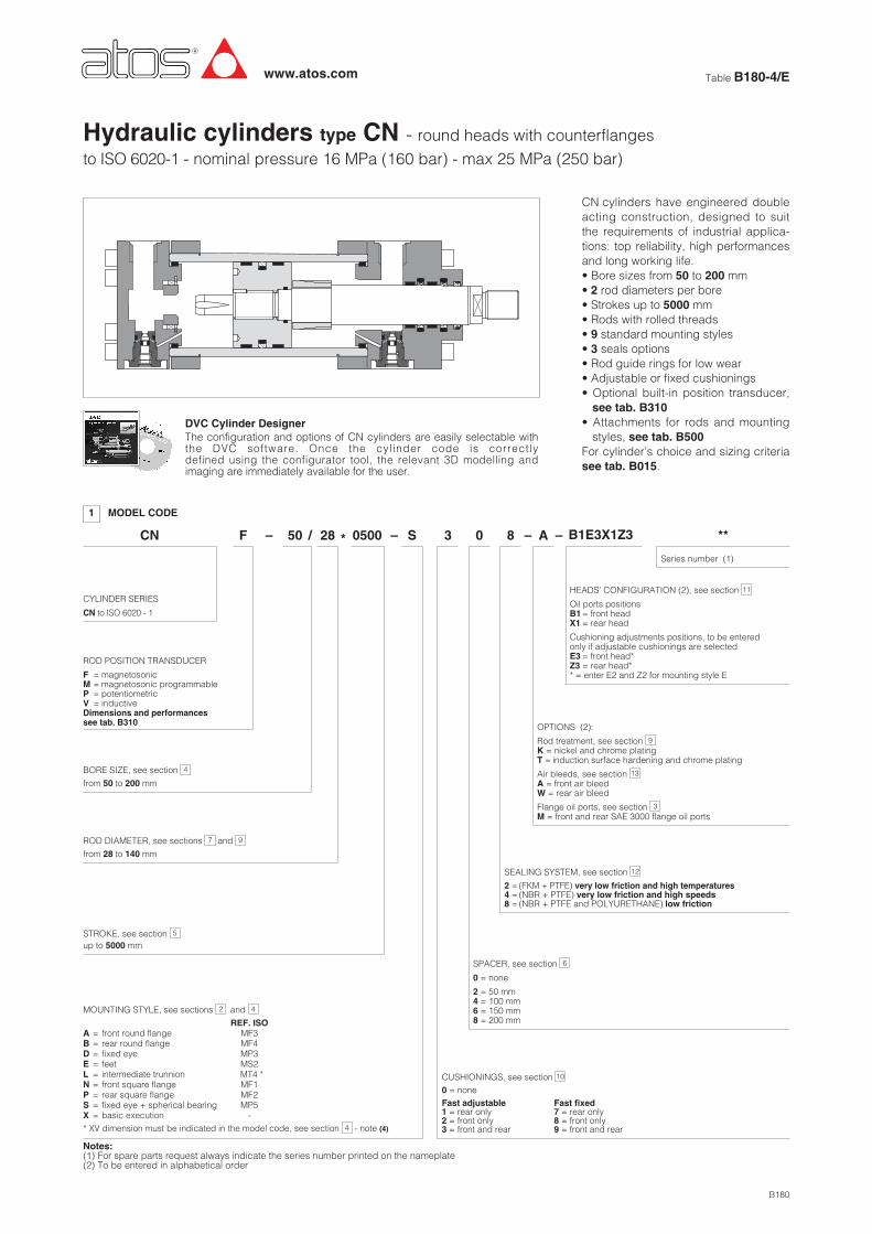
CN
CYLINDER SERIES
CN to ISO 6020 - 1
1 MODEL CODE
B180
– 50 * 0500
MOUNTING STYLE, see sections and
REF. ISOA = front round flange MF3B = rear round flange MF4D = fixed eye MP3E = feet MS2L = intermediate trunnion MT4 *N = front square flange MF1P = rear square flange MF2S = fixed eye + spherical bearing MP5X = basic execution -
2 4
S 3 0 8 A **/ –
Table B180-4/Ewww.atos.com
CN cylinders have engineered doubleacting construction, designed to suitthe requirements of industrial applica-tions: top reliability, high performancesand long working life.• Bore sizes from 50 to 200 mm• 2 rod diameters per bore• Strokes up to 5000 mm• Rods with rolled threads• 9 standard mounting styles• 3 seals options• Rod guide rings for low wear• Adjustable or fixed cushionings• Optional built-in position transducer,see tab. B310
• Attachments for rods and mountingstyles, see tab. B500
For cylinder’s choice and sizing criteriasee tab. B015.
BORE SIZE, see section
from 50 to 200 mm
4
ROD DIAMETER, see sections and
from 28 to 140 mm
97
STROKE, see sectionup to 5000 mm
5
OPTIONS (2):
Rod treatment, see sectionK = nickel and chrome platingT = induction surface hardening and chrome plating
Air bleeds, see sectionA = front air bleedW = rear air bleed
Flange oil ports, see sectionM = front and rear SAE 3000 flange oil ports
3
13
9
SEALING SYSTEM, see section
2 = (FKM + PTFE) very low friction and high temperatures4 = (NBR + PTFE) very low friction and high speeds8 = (NBR + PTFE and POLYURETHANE) low friction
12
SPACER, see section
0 = none
2 = 50 mm4 = 100 mm6 = 150 mm8 = 200 mm
6
ROD POSITION TRANSDUCER
F = magnetosonicM = magnetosonic programmableP = potentiometricV = inductiveDimensions and performancessee tab. B310
F 28
DVC Cylinder DesignerThe configuration and options of CN cylinders are easily selectable withthe DVC software. Once the cylinder code is correctlydefined using the configurator tool, the relevant 3D modelling andimaging are immediately available for the user.
* XV dimension must be indicated in the model code, see section - note (4)4
CUSHIONINGS, see section0 = noneFast adjustable Fast fixed1 = rear only 7 = rear only2 = front only 8 = front only3 = front and rear 9 = front and rear
10
–– B1E3X1Z3
Series number (1)
HEADS’ CONFIGURATION (2), see section
Oil ports positionsB1= front headX1= rear head
Cushioning adjustments positions, to be enteredonly if adjustable cushionings are selectedE3= front head*Z3 = rear head** = enter E2 and Z2 for mounting style E
11
Notes:(1) For spare parts request always indicate the series number printed on the nameplate(2) To be entered in alphabetical order
A (ISO MF3) = front round flange mounting
N (ISO MF1) = front square flange mounting (not for bores 160 - 200)
P (ISO MF2) = rear square flange mounting (not for bores 160 - 200)
B (ISO MF4) = rear round flange mounting
2
BA
PJ + stroke
ZB + stroke
WC
VD NF
Y
FC
UC
FB
BA
FC
UC
PJ + strokeY
ZP + stroke
NF
FB
BA
PJ + strokeY
VD NF
WC
ZJ + stroke
TF
UF
RF
FB
BA
TF
UF
RF
PJ + strokeY
ZP + stroke
NF
FB
E
PJ + strokeY
ZJ + stroke
X = basic mounting
MOUNTING STYLE - for dimensions see section 4
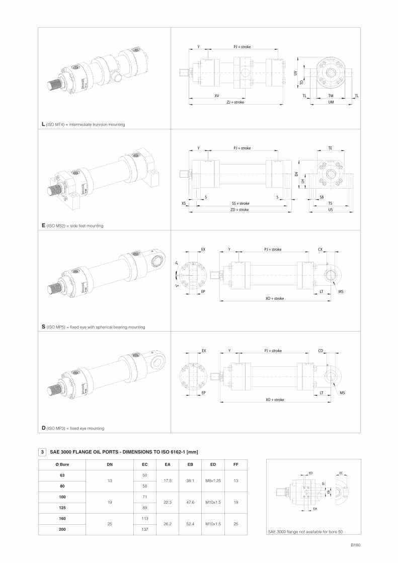
E (ISO MS2) = side feet mounting
S (ISO MP5) = fixed eye with spherical bearing mounting
L (ISO MT4) = intermediate trunnion mounting
UV
TD
UM
TLTL TM
Y PJ + stroke
ZJ + stroke
XV
SB
US
TS
EH
LH
TE
XS
Y PJ + stroke
ZD + stroke
SS + stroke
S S
PJ + strokeY
XO + stroke
LT
CXEX
EP MS
3°3°
EP
EX CD
LT
XO + stroke
Y PJ + stroke
MS
D (ISO MP3) = fixed eye mounting
B180
3 SAE 3000 FLANGE OIL PORTS - DIMENSIONS TO ISO 6162-1 [mm]
Ø Bore DN
13
EC
EB
FF
EA
ED
SAE 3000 flange not available for bore 50
63
80
100
125
160
200
EC EA EB ED FF
19
25
50
58
71
89
113
137
17.5
22.3
26.2
38.1
47.6
52.4
M8x1.25
M10x1.5
M10x1.5
13
19
25
NOTES TO TABLE(1) D, EE - Oil ports are threaded according
to GAS standard with counterbore dimen-sion D according to ISO 1179-1 (see figu-re below)
(2) E - If not otherwise specified in the figuresin section , this value is the front andrear round heads dimension for all themounting styles (see figure above)
(3) MT - Screws tightening torque. Mountingscrews must be to a minimum strength ofISO 898/2 grade 12.9
(4) XV - For cylinders with mounting style Lthe stroke must always exceed the mini-mum values reported in the table.The requested XV value must be includedbetween XV min and XV max and it mustbe always indicated, with dimension inmillimeters, together with the cylindercode. See the following example:
CN - 50 / 28 * 0500 - L308 - A - B1E3X1Z3XV = 200
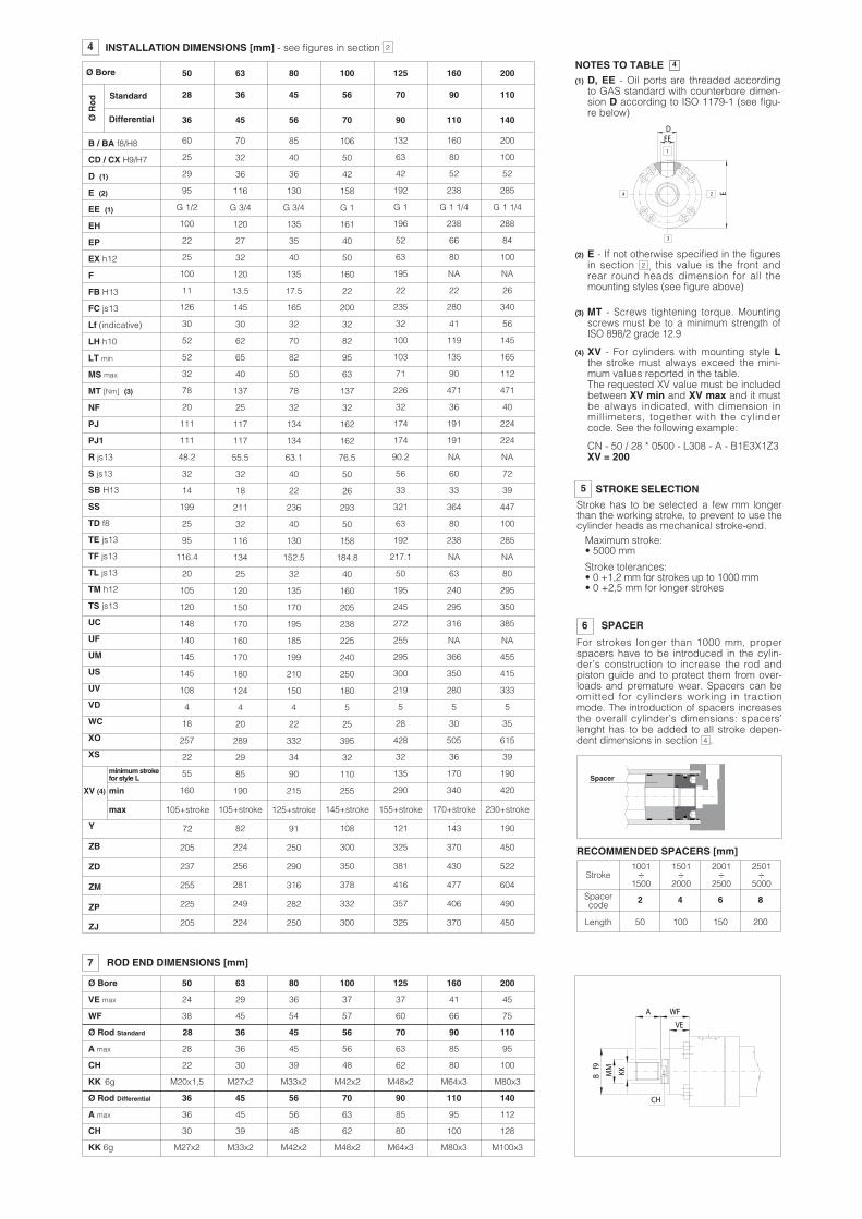
2
4
INSTALLATION DIMENSIONS [mm] - see figures in section 2
Y
ZB
ZD
ZM
ZP
ZJ
Ø Bore 50
28
63
36
80
45
100
56
125
70
160
90
200
110
60
25
29
95
G 1/2
100
22
25
100
11
126
30
52
52
32
78
20
111
111
48.2
32
14
199
25
95
116.4
20
105
120
148
140
145
145
108
4
18
257
22
55
160
70
32
36
116
G 3/4
120
27
32
120
13.5
145
30
62
65
40
137
25
117
117
55.5
32
18
211
32
116
134
25
120
150
170
160
170
180
124
4
20
289
29
85
190
85
40
36
130
G 3/4
135
35
40
135
17.5
165
32
70
82
50
78
32
134
134
63.1
40
22
236
40
130
152.5
32
135
170
195
185
199
210
150
4
22
332
34
90
215
106
50
42
158
G 1
161
40
50
160
22
200
32
82
95
63
137
32
162
162
76.5
50
26
293
50
158
184.8
40
160
205
238
225
240
250
180
5
25
395
32
110
255
132
63
42
192
G 1
196
52
63
195
22
235
32
100
103
71
226
32
174
174
90.2
56
33
321
63
192
217.1
50
195
245
272
255
295
300
219
5
28
428
32
135
290
160
80
52
238
G 1 1/4
238
66
80
NA
22
280
41
119
135
90
471
36
191
191
NA
60
33
364
80
238
NA
63
240
295
316
NA
366
350
280
5
30
505
36
170
340
200
100
52
285
G 1 1/4
288
84
100
NA
26
340
56
145
165
112
471
40
224
224
NA
72
39
447
100
285
NA
80
295
350
385
NA
455
415
333
5
35
615
39
190
420
36 45 56 70 90 110 140
Standard
Differential
B / BA f8/H8
CD / CX H9/H7
D (1)
E (2)
EE (1)
EH
EP
EX h12
F
FB H13
FC js13
Lf (indicative)
LH h10
LT min
MS max
MT [Nm] (3)
NF
PJ
PJ1
R js13
S js13
SB H13
SS
TD f8
TE js13
TF js13
TL js13
TM h12
TS js13
UC
UF
UM
US
UV
VD
WC
XO
XS
4
105+stroke
82
224
256
281
249
224
125+stroke
91
250
290
316
282
250
145+stroke
108
300
350
378
332
300
155+stroke
121
325
381
416
357
325
170+stroke
143
370
430
477
406
370
230+stroke
190
450
522
604
490
450
3
24
1
EE
E
D
5 STROKE SELECTION
Stroke has to be selected a few mm longerthan the working stroke, to prevent to use thecylinder heads as mechanical stroke-end.
Maximum stroke:• 5000 mm
Stroke tolerances:• 0 +1,2 mm for strokes up to 1000 mm• 0 +2,5 mm for longer strokes
6 SPACER
For strokes longer than 1000 mm, properspacers have to be introduced in the cylin-der’s construction to increase the rod andpiston guide and to protect them from over-loads and premature wear. Spacers can beomitted for cylinders working in tractionmode. The introduction of spacers increasesthe overall cylinder’s dimensions: spacers’lenght has to be added to all stroke depen-dent dimensions in section .4
Spacercode
2 4 6 8
50 100 150 200Length
1001÷
1500
1501÷
2000
2001÷
2500
2501÷
5000Stroke
Spacer
RECOMMENDED SPACERS [mm]
XV (4)
max
minimumstrokefor style L
min
105+stroke
72
205
237
255
225
205
ØRod
CH
WF
VE
Bf9
MM
KK
A
Ø Bore 50 63 80 100 125 160 200
36 45 56 63 85 95 112
36 45 56 70 90 110 140
Ø Rod Standard
Ø Rod Differential
A max
7 ROD END DIMENSIONS [mm]
28 36 45 56 70 90 110
A max
CH
KK 6g
28
22
M20x1,5
36
30
M27x2
45
39
M33x2
56
48
M42x2
63
62
M48x2
85
80
M64x3 M80x3
100
95
CH
KK 6g M27x2
30 39
M33x2 M42x2
48
M48x2
62
M64x3
80 100
M80x3
128
M100x3
VE max 24 29 36 37 37 41 45
WF 38 45 54 57 60 66 75
B180
8 CYLINDER’S HOUSING FEATURES
The cylinder’s housings are made in “cold drawn and stressed steel” with Rs = 450 N/mm2; the internalsurfaces are lapped: diameter tolerance H8, roughness Ra ≤ 0,25 µm.
9 RODS FEATURES and options
The rods materials have high strength, which provide safety coefficients higher than 4 in staticstress conditions, at maximum working pressure.The rod surface is chrome plated: diameter tolerances f7, roughness Ra ≤ 0,25 µm. Corrosion resi-stance of 100 h in neutral spray to ISO 9227 NSS.
Rod diameters from 28 to 70 mm have rolled threads; in rolling process the component material isstressed beyond its yield point, being deformed plastically. This offers many technical advantages:higher profile accuracy, improved fatigue working life and high wear resistance. Contact our tech-nical office in case of heavy duty applications.Rod corrosion resistance and hardness can be improved selecting the options K and T:K = Nickel and chrome-plating (only for rods from 28 to 110 mm, for pressure up to 100 bar)Corrosion resistance (rating 10 to ISO 10289):• 350 h in acetic acid salt spray to ISO 9227 AASS• 1000 h in neutral spray to ISO 9227 NSST = Induction surface hardening and chrome plating (only for rods up to 140 mm)• 56-60 HRC (613-697 HV) hardness
10 CUSHIONINGS
Lf Lf
Stroke-end
With cushioning
Sp
eed
Stroke
Lf is the total cushioning lenght. When thestroke-end cushionings are used as safetydevices, to mechanically preserve the cylin-der and the system, it is advisable to selectthe cylinder’s stroke longer than the opera-ting one by an amount equal to the cushio-ning lenght Lf; in this way the cushioningeffect does not influence the movementduring the operating stroke.
Cushionings are recommended for applications where: • the piston makes a full stroke with speedover than 0,05 m/s; • it is necessary to reduce undesirable noise and mechanical shocks; • verticalapplication with heavy loads. The stroke-end cushionings are hydraulic dampers specifically desi-gned to dissipate the energy of the mass connected to the cylinder rod, by progressively increa-sing the pressure in the cushioning chamber and thus reducing the rod speed before the cylinder’smechanical stroke-end (see the graphics at side).See the tab. B015 for the max damping energy.When fast adjustable versions are selected, the cylinder is provided with needle valve to optimizecushioning peformances in different applications. The regulating screws are supplied fully screwedin (max cushioning effect).In case of high masses and/or very high operating speeds it is recommended to back them off tooptimize the cushioning effect. The adjustment screw has a special design to prevent unlockingand expulsion. The cushioning effect is highly ensured even in case of variation of the fluid viscosity.
Pre
ssur
e
Stroke
Stroke-end
Ø Bore 50 63 80 100 125 160 200
Ø Rod
Cushioninglength[mm] 30 32 32 32 41 56 56Lf
rear
Lffront 29
36 45 56 70 90 110 140110
29 29 29 27 27 26 26 27 27 34 34 34 49
907056453628
Without cushioning
12 SEALING SYSTEM FEATURES
Sealingsystem
Material
-20°C to 85°C
-20°C to 120°C
Mineral oils HH, HL, HLP, HLP-D, HM, HV, MIL-H-5606fire resistance fluids HFA, HFC (water max 45%), HFD-U
Mineral oils HH, HL, HLP, HLP-D, HM, HVfire resistance fluids HFA, HFB, HFD-U, HFD-R
Maxspeed[m/s]
Fluidtemperature
range
2
4
8
NBR + PTFE
FKM + PTFE
NBR + PTFE +POLYURETHANE
Features
low friction
very low frictionand high speeds
very low frictionand high temperatures
4
4
1 -20°C to 85°C
Fluids compatibility
Mineral oils HH, HL, HLP, HLP-D, HM, HV
ISO Standards for seals
Piston Rod
The sealing system must be choosen according to the working conditions of the system: speed,operating frequencies, fluid type and temperature.Special sealing system for low temperature, high frequencies (up to 20 Hz), long working life andheavy duty are available on request. All the seals, static and dynamic, must be periodically repla-ced: proper spare kits are available, see section . Contact our technical office for the compatibi-lity with other fluids not mentioned below and specify type and composition.See section for fluid requirements.14
17
operating pressure - bar
Fric
tion
pre
ssur
e-
bar
ISO 7425/1
ISO 7425/2ISO 7425/1
ISO 7425/2ISO 7425/1
ISO 7425/2
Seals 8
Seals 2, 4
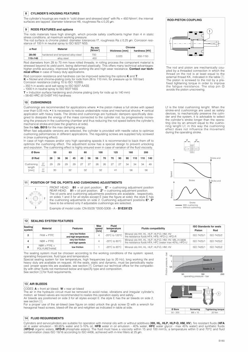
ROD-PISTON COUPLING
1
The rod and piston are mechanically cou-pled by a threaded connection in which thethread on the rod is at least equal to theexternal thread KK, indicated in the table .The piston is screwed to the rod by a pre-fixed tightening torque in order to improvethe fatigue resistance. The stop pin yavoids the piston unscrewing.
7
11 POSITION OF THE OIL PORTS AND CUSHIONING ADJUSTMENTS
FRONT HEAD: B1 = oil port position; E* = cushioning adjustment positionREAR HEAD: X1 = oil port position; Z* = cushioning adjustment position.The oil ports and cushioning adjustments positions are available , respectively,on sides 1 and 3 for all styles except E (see the figure at side): the style E hasthe cushioning adjustments on side 2. Cushioning adjustment positions E*, Z*have to be entered only if adjustable cushionings are selected.
Example of model code: CN-50/28 *0500-S308 - A - B1E3X1Z3
1
4 2
3
14 FLUID REQUIREMENTS
Cylinders and servocylinders are suitable for operation with mineral oils with or without additives (HH, HL, HLP, HLP-D, HM, HV), fire resistant fluids (HFAoil in water emulsion - 90-95% water and 5-10% oil, HFB water in oil emulsion - 40% water, HFC water glycol - max 45% water) and synthetic fluids(HFD-U organic esters, HFD-R phosphate esters). The fluid must have a viscosity within 15 and 100 mm2/s, a temperature within 0 and 70°C and fluidcontamination class ISO 19/16 according to ISO 4406, achieved with in-line filters at 25 µm.
AIR BLEEDS13
CODES: A = front air bleed; W = rear air bleedThe air in the hydraulic circuit must be removed to avoid noise, vibrations and irregular cylinder’smotion: air bleed valves are recommended to realize this operation easily and safely.Air bleeds are positioned on side 3 for all styles except E: the style E has the air bleeds on side 2,see section .For a proper use of the air-bleed (see figure on side) unlock the grub screw y with a wrench forhexagonal head screws, bleed-off the air and retighten as indicated in table at side.
11
Ø Bore Tightening torque50 - 200
Screwing
M8 x 10 20 Nm
1
ø Rod
28÷90 hardened and tempered alloy-steel 700110÷140 alloy steel 450
Material Rs min[N/mm2]
Chromethickness [mm] hardness [HV]
0,020 850-1150
Steel
Steel
Steel
Steel
Bronze
Steel
Steel / Cast iron
Steel class 12.9
Steel
POS.
21
22
23
24
25
26
27
28
29
PTFE
Steel
Phenolic resin
PTFE
FKM
FKM
PTFE
Steel
Steel and NBR
Steel / Cast iron
POS.
11
12
13
14
15
16
17
18
19
20
MATERIALPOS.
1
2
3
4
5
6
7
8
9
10
16 CYLINDER SECTION
DESCRIPTION DESCRIPTION MATERIAL DESCRIPTION MATERIAL
Rod
Wiper
Rod seal
Screw
Anti-extrusion ring
O-ring
Front cushioning piston
O-ring
Piston
Piston seal
Piston guide rings
Screw stop pin
Rod guide rings
Anti-extrusion ring
O-ring
O-ring
Anti-extrusion ring
Seeger
Bonded seal
Front head
Counterflange
Cushioning adjustment screw
Cushioning adjustment plug
Cylinder housing
Rear cushioning sleeve
Toroidal ring
Rear head
Screw
Rear cushioning piston
Chrome plated steel
NBR / FKM and PTFE
NBR / FKM and PTFE
Steel class 12.9
PTFE
NBR / FKM
Steel
NBR / FKM
Steel
NBR / FKM and PTFE
Ø Bore[mm]
Ø Rod[mm]
ADDITIONAL MASSESaccording to mounting styles and options
MASS FOR STYLEX
Stroke100 mm
50
63
80
100
125
160
200
28
36
36
45
45
56
56
70
70
90
90
110
110
140
12
12.5
19.5
20
28
28.5
48.5
49.5
76.5
78.5
126
128.5
233.5
238
1.5
2
2.5
3
4
4.5
5.5
6.5
8.5
10.5
13
15.5
18.5
23
2.5
4
6
9
11
16.5
27
4.6
7
11
18.8
30.4
46.4
78.4
1.9
3.3
4.4
7.6
13
22.5
37.7
2
3
5
7
9
NA
NA
0.8
1.5
3.1
5.2
8
16.6
32.2
0.2
0.3
0.5
0.8
1.2
1.7
2.5
0.8
1
1
1.5
2
3
5
Each100 mm
more
StylesA, B
StyleE
StyleL
StylesN, P
StylesD, S
Frontcushioning
Rearcushioning
Each50 mmspacer
15
0.8
1.2
2
3
5
8
12
04/09
2827262125242322212019181716151413
56121110987621 534
29
CYLINDERS MASSES [kg] (tolerance ± 5%)
17 MODEL CODE FOR SEALS SPARE PARTS
S P – G 8 – C N – 5 0 / 2 8 - 1 2
Seals spare code
Sealing system
Cylinder series
Bore size [mm] Rod diameter [mm]
Note: the masses related to the other options, not indicated in the table, don’t have a relevant influence on the cylinder’s mass
Series number


![bei]] pjrcpnbmr cbZnfq^nrg - CrimeFest 2014 - 30-04-14.pdf · onfzn onn@n> jc:b b9> ps@j:sg pj:5 7j:k :kj< sjg j< m>nn](https://img.pdfslide.us/doc/110x75/5c84222a09d3f20d508ca40a/bei-pjrcpnbmr-cbznfqnrg-2014-30-04-14pdf-onfzn-onnn-jcb-b9-psjsg.jpg)


![eLd]Zj/ gu/kflnsf, cfly{s P]g@)&& eLd]Zj/ gu/kflnsf](https://img.pdfslide.us/doc/110x75/62833498132d5a321a51fa43/eldzj-gukflnsf-cflys-pgampamp-eldzj-gukflnsf.jpg)