Embed Size (px)
Citation preview

MCFRS Driver Certification Program 1 of 24 Rescue Squad – Module 5
Hydraulic Tools and Equipment
Introduction
Hydraulic tools are an important part of a rescue squad’s inventory. They are the
backbone of most vehicle extrications and offer an excellent option for heavy lifting
operations. As a driver/operator, it is important to understand all aspects of hydraulic tools
including not only the tool itself, but their source of power, associated accessories and
even the science behind their operation.
Theory
Fluid Mechanics
Hydraulics is the branch of science that deals with the practical applications (as
transmission of energy or effects of flow) of liquid in motion. A large part of the theoretical
foundation for hydraulics is derived from fluid mechanics, which is the study of the effects
of forces and energy on liquids and gases. The term “fluid” is often used interchangeably
with the term “liquid”. However, a liquid is actually a type of fluid. Fluids are defined as
substances that have a tendency to freely flow or conform to the shape of their container.
Both liquids and gases meet this criteria and are considered fluids. Therefore hydraulics
is the equivalent of pneumatics when dealing with liquids instead of gases.
All fluids are compressible to some extent (changes in pressure and/or temperature will
result in changes in their density). However, in most applications the
pressure/temperature changes are so small that any changes in density are negligible.
Therefore, fluids are often grouped into two categories:
Compressible – a fluid whose density significantly changes with changes in
pressure; the volume of a compressible fluid decreases as the pressure exerted
on the fluid increases; gases are often considered compressible fluids
Incompressible – a fluid whose density does not significantly change with
pressure; the volume of an incompressible fluid will not change as the pressure
exerted on the fluid increases; liquids are often considered incompressible fluids
Pressure
Before proceeding further, it is important to review the definition of pressure. Pressure is
force per unit area applied in a direction perpendicular to the surface of an object.
Pressure Force
Area

Hydraulic Tools and Equipment Rev. 1/1/15
MCFRS Driver Certification Program 2 of 24 Rescue Squad – Module 5
Pressure (continued)
The SI unit of pressure is the pascal (Pa = N/m2). The U.S. customary system unit of
pressure is pounds per square inch (psi = lbs/in2). As the equation on the previous page
shows, pressure is affected by changes in the force being applied or the area in which
the force is applied.
Pascal’s Law
One important principle relating to fluid mechanics is Pascal’s Law. The law states that
any change in pressure at any point in a confined fluid will result in an equal change in
pressure (without loss) throughout the rest of the fluid and to the walls of the container.
Example 1:
The container on the left contains a fluid. Three
pressure gauges are connected to the container at
different depths. As the depth of the fluid
increases, the pressure increases due to the mass
above it.
An additional pressure of 4 psi is applied to the
fluid. As a result, the pressure will increase
throughout the fluid. According to Pascal’s Law,
the pressure increase throughout all parts of the
container will be equal. Therefore, each pressure
gauge will increase by 4 psi.
The above example illustrates Pascal’s Law at a basic level. The next example will
demonstrate Pascal’s Law in a slightly more complex system. This example will show
how forces can be multiplied in hydraulic systems, providing the basis for the design of
hydraulic rescue tools.
P1 = 2 PSI
P2 = 4 PSI
P3 = 6 PSI
P1 = 6 PSI
P2 = 8 PSI
P3 = 10 PSI

Hydraulic Tools and Equipment Rev. 1/1/15
MCFRS Driver Certification Program 3 of 24 Rescue Squad – Module 5
Example 2:
Example 2 demonstrates how a hydraulic lift operates at a basic level. A force is applied
to the piston on the left. This force causes an increase in pressure on the hydraulic
system, which is transmitted to the cylinder on the right. The pressure acts on the piston
on the right, which transmits force to lift the block. One very important aspect of the
system shown above is that only 10 lbs. on input force is required to lift the 100 lb. block.
How can this be? The answer can be drawn from Example 1 and the application of
Pascal’s Law:
Remember, Pressure (P) = Force (F) / Area (A)
So from the diagram, the pressure in the cylinder on the left is:
Pressure = Force on Piston 1 / Area of Piston 1
Pressure = 10 lbs / 1 in2 = 10 lbs/in2 = 10 psi
Pascal’s Law states that the pressure in the entire system must be equal. Therefore, if
there is 10 psi in the cylinder on the left, there will be 10 psi in the cylinder on the right.
For the cylinder on the right, the pressure is known. Rearranging the equation yields:
Force (F) = Pressure (P) x Area (A)
Force on Piston 2 = (Pressure) x (Area of Piston 2)
Force on Piston 2 = (10 lbs/in2) x (10 in2) = 100 lbs
As this example shows, the input force is increased (multiplied) by a factor of 10 because
the area of Piston 2 is 10x that of Piston 1.
Force = 10 lbs. Load = 100 lbs.
Piston 1
Area = 1 in2
Piston 2
Area = 10 in2

Hydraulic Tools and Equipment Rev. 1/1/15
MCFRS Driver Certification Program 4 of 24 Rescue Squad – Module 5
Another noteworthy point from Example 2 is the fact that Piston 1 moves farther than
Piston 2:
The input force was multiplied by a factor of 10 but the resulting movement of the load
was reduced by the same factor of 10. It is often said that, “nothing in life is free”. Fluid
mechanics is no different. The size and shape of the cylinders does not change.
Therefore, since the pressure of the liquid remains the same, the volume must remain
constant as well.
The volume of liquid in the cylinder can be expressed as:
Volume (V) = Area of the Piston (A) x Distance the Piston Moves (D)
Therefore, for the cylinder on the left:
Volume = (Area of Piston 1) x (Distance Piston 1 Moves)
Volume = (1 in2) x (10 in) = 10 in3
If 10 in3 of liquid is displaced in the cylinder on the left, 10 in3 of liquid must move to the
cylinder on the right. Since the volume is known, the equation can be rearranged:
Distance the Piston Moves (D) = Volume (V) / Area of the Piston (A)
For the cylinder on the right:
Distance Piston 2 Moves = Volume / Area of Piston 2
Distance Piston 2 Moves = 10 in3 / 10 in2 = 1 in
Therefore, the tradeoff to gain increased output force is a decrease in lifting height.
Piston 1
moves 10 in
Piston 2
moves 1 in
Piston 1
Area = 1 in2
Piston 2
Area = 10 in2

Hydraulic Tools and Equipment Rev. 1/1/15
MCFRS Driver Certification Program 5 of 24 Rescue Squad – Module 5
Hydraulic System Components
At a basic level, most hydraulic systems are made up of the following components:
Fluid
Reservoir
Pump
Actuator
Valves
All of these components can be of different designs and complexities depending on the
hydraulic systems application.
Fluid
Hydraulic fluid (or more accurately, “liquid”) is the medium for carrying the pressure
through a hydraulic system that is translated into mechanical force and movement. There
is a large variety of options for hydraulic fluid, each with specific characteristics to match
specific applications. Some of the basic features of an “ideal” hydraulic fluid include:
Thermal stability
Hydrolytic stability (the ability to resist
chemical decomposition in the presence
of water)
Low chemical corrosiveness
High anti-wear characteristics
Long life
Low cost
To meet these demands, oil-based hydraulic
fluids are often utilized. These fluids can be
engineered to provide the desired viscosity,
anti-wear and anti-corrosion properties with few
operating, safety or maintenance problems.
However, there are certain applications where oil-based fluids should be avoided.
Fire/rescue operations are examples of such situations. Hydraulic fluid exposure to high
heat and/or flame could potentially result in a significant fire hazard. For this reason, most
fire/rescue-specific hydraulic fluids fall into the category of fire-resistant hydraulic fluids
(FRHFs).

Hydraulic Tools and Equipment Rev. 1/1/15
MCFRS Driver Certification Program 6 of 24 Rescue Squad – Module 5
The increased demand for fire-resistant hydraulic fluids came about from tragic incidents
involving hydraulic fluid fires in industries such as steel mills, foundries and coal mines.
Research was aimed at finding suitable replacements for oil-based fluids that could
provide comparable hydraulic system performance without a significant increase in cost.
Water-Containing Fire-Resistant Fluids:
One solution to the problem of fire resistance is water. The introduction of water into
hydraulic fluid provides an extinguishing agent should the fluid be exposed to flame.
Water glycol and invert emulsions are the two major types of water-containing FRHFs:
Water glycol – a solution of glycol (e.g. ethylene glycol) in water
o Contains a variety of additives to provide viscosity, anti-wear and corrosion
protection properties as well as a polymeric thickener
o Approximately 40% water content
o One of the dominant FRHFs on the market
o Presents some environmental concerns
Invert emulsion – a stable emulsion of water in oil
o Also contains approximately 40% water
o The outer phase of oil represents the wetting surface and provides the
desired characteristics of oil-based hydraulic fluids
o The inner phase of water acts as the fire-retardant
o Contains oil-soluble additives to provide corrosion protection and reduce
wear as well as emulsion stability
Synthetic Fire-Resistant Fluids:
The other approach to providing fire resistance was to engineer non-aqueous fluids with
chemical properties that either resisted burning or generated products of combustion that
would help extinguish any flames. The intent of these fluids was to eliminate the use of
water, therefore eliminating the undesirable corrosive and wear characteristics.
Phosphate Esters – the product of a reaction between phosphoric acid and
aromatic ring-structure alcohols
o Extremely fire resistant
o Provide excellent wear resistance
Polyol Esters – synthetic hydrocarbon, the product of a
reaction between long-chain fatty acids (derived from animal
and vegetable fats) and synthesized organic alcohols
o Good fire resistance
o Contain additives to provide anti-wear properties,
corrosion protection and viscosity modification
o Biodegradable

Hydraulic Tools and Equipment Rev. 1/1/15
MCFRS Driver Certification Program 7 of 24 Rescue Squad – Module 5
Reservoir
The reservoir is simply the storage tank for hydraulic fluid. Reservoirs come in different
shapes and sizes depending upon the application. They are designed to provide sufficient
fluid capacity for the rated number of operating tools while also maintaining a reserve. In
addition, the reservoir must be large enough to hold the hydraulic systems fluid volume
when the tools are not in use. In many cases, the reservoir is mounted in close proximity
to the hydraulic pump.
Pump
The hydraulic pump is the device that produces liquid movement or flow. (It is important
to note that pumps do NOT generate pressure. In liquids, pressure is a function of
resistance to flow. A pump’s job is to generate that flow.)
As a review from a “Pumps and Hydraulics” class, pumps are classified as either positive-
displacement or non-positive displacement. Most pumps
used in hydraulic systems are positive displacement. Positive
displacement pumps displace (or move) the same amount of
liquid for each cycle of the pumping element. The precise and
consistent liquid delivery is possible due to tight tolerances
between the pumping element and pump housing.
Positive displacement pumps include reciprocating- and
rotary-type. Reciprocating pumps are some of the most basic
types of positive-displacement pumps. They contain an inlet
and outlet and cylinder and piston.
Rotary pumps include gear pumps (both external and internal), vane pumps and piston
pumps.
Spur Gear Pump Balanced Vane Pump Axial-Piston Pump

Hydraulic Tools and Equipment Rev. 1/1/15
MCFRS Driver Certification Program 8 of 24 Rescue Squad – Module 5
Power Sources
Hydraulic pumps can be powered several different ways:
Manually-operated – for use with single-action
reciprocating positive displacement pumps
Electric motor – can be DC or AC operated;
common power source for many apparatus-mounted hydraulic pumps
Internal combustion engine – provides portability options; common type is a 4-
stroke gasoline small engine
Air pressure – compressed air powers the pump
Power Take-Off (PTO) driven – PTOs can be mounted
to the truck transmission and
engaged via a switch in the cab; the
hydraulic pump is often connected
directly to the PTO
PTO Pump

Hydraulic Tools and Equipment Rev. 1/1/15
MCFRS Driver Certification Program 9 of 24 Rescue Squad – Module 5
Actuator
The hydraulic fluid, pump and power source generate flow and pressure. As described in
the first section of this module, this pressure needs to be converted back to force and
displacement. This is the job of the actuator.
Actuators can classified into two types:
Linear (hydraulic cylinders) – convert pressure and flow into linear force and
displacement
Rotary (hydraulic motors) – convert pressure and flow into torque and angular
displacement
Hydraulic motors are used for a variety of things in the fire service. Two common
examples are rotation of aerial ladders and hydraulic winches. Hydraulic cylinders control
extension and elevation of aerial ladders and many of the hydraulic tools on rescue
squads and other rescue apparatus.
Types of Hydraulic Cylinders
There are two common types of hydraulic cylinders:
Single-Acting – This type of cylinder is unidirectional (operates in one direction).
Hydraulic fluid flows into the head of the cylinder through a single port and pushes
on the piston, extending the rod. To retract the piston, a valve must be opened to
allow fluid to flow back to the reservoir. The piston retraction is made possible
either by gravity, the weight of the load or a mechanical force, such as a spring.
Examples of single-acting cylinders are floor jacks and bottle jacks.
Hydraulic
Fluid Port Air Vent Piston Rod

Hydraulic Tools and Equipment Rev. 1/1/15
MCFRS Driver Certification Program 10 of 24 Rescue Squad – Module 5
Double-Acting – This type of cylinder is bidirectional (operates in two directions).
Unlike single-acting cylinders, there are two ports on a double-acting cylinder, one
at each end. To extend the piston, fluid flows from the pump into the port at the
cylinder head. As the piston extends, fluid on the opposite side of the piston exits
the cylinder through the other port and returns to the reservoir. To retract the
piston, a directional valve reverses the fluid flow. Most hydraulic rescue tools
utilize double-acting cylinders.
One special design of a hydraulic cylinder is the telescoping cylinder. These cylinders
contain multiple tubes of progressively smaller diameters nested within each other. Each
individual tube represents a stage. Telescoping cylinders have the distinct advantage of
increased length at full extension while maintaining a relatively short retracted length.
These cylinders can be found in both single- and double-acting designs.
Hydraulic
Fluid Port
Hydraulic
Fluid Port Piston Rod

Hydraulic Tools and Equipment Rev. 1/1/15
MCFRS Driver Certification Program 11 of 24 Rescue Squad – Module 5
Valves
The valves in a hydraulic system control the movement of hydraulic fluid. They are used
to control flow between the reservoir and the pump, the pump and the actuator, and flow
within the actuator itself.
Single-acting cylinders typically have a valve or set of valves to control flow between the
reservoir, pump and the hydraulic cylinder. They also contain a valve that allows fluid to
return from the cylinder to the reservoir.
The diagrams on the right show the basic
components of a bottle jack. They
contain a single-acting cylinder and a
reservoir that actually surrounds the
cylinder. The pump is a reciprocating
style that is manually operated.
Fluid flow between the reservoir and
pump and the pump and cylinder is
controlled by two ball valves.
In the top diagram, the ball valve
between the reservoir and pump is open,
allowing fluid to flow from the reservoir to
the pump. The ball valve between the
pump and cylinder remains closed.
In the middle diagram, the ball valve
between the reservoir and pump closes
while the ball valve between the pump
and cylinder opens. This allows fluid
under pressure to flow into the cylinder,
creating lift.
The bottom diagram shows the operation
of the release valve. This valve is opened
to allow fluid to flow from the cylinder
directly to the reservoir, enabling the
piston to retract. Gravity along with the
weight of the load and piston create the
fluid movement.

Hydraulic Tools and Equipment Rev. 1/1/15
MCFRS Driver Certification Program 12 of 24 Rescue Squad – Module 5
Double-acting cylinders, such as those on most hydraulic rescue tools, have a slightly
different set of valves. One of the valves controls the direction of flow within the actuator.
Another valve controls the flow between the reservoir, pump and actuator.
The diagrams on the right
show the basic operation
of the control valve on a
hydraulic rescue tool.
There are three different
positions: Neutral, Extend
and Retract.
The top diagram shows
the Neutral position. Fluid
flow from the pump is
blocked from entering the
cylinder.
In the middle diagram, the
tool operator rotates the
control valve to the
Extend position. Fluid is
able to flow into the
cylinder, pushing on the
piston and extending the
rod.
In the bottom diagram,
the tool operator rotates
the control valve to the
Retract position. Fluid
flow within the cylinder
reverses direction. It now
pushes on the opposite side of the piston, retracting the rod.
One noteworthy point about the double-acting cylinder shown above is that the surface
areas on each side of the piston are not equal. The surface area on the left is decreased
by the presence of the piston rod. This decrease in surface area results in a decrease in
force applied through the piston rod during retraction.
To the
Reservoir
From
the
Pump

Hydraulic Tools and Equipment Rev. 1/1/15
MCFRS Driver Certification Program 13 of 24 Rescue Squad – Module 5
Most hydraulic rescue tool systems also have a valve that controls the flow of hydraulic
fluid to the tool. This valve has two positions. One position pressurizes the port going to
the tool. The other position is a neutral, or “dump”, position that bypasses the tool port
and recirculates (dumps) the hydraulic fluid back to the reservoir.
The diagrams below show the basic operation of the dump valve.
The diagram on the left shows the valve in the neutral position. Pressurized fluid from the
pump is immediately returned to the reservoir. The diagram on the right shows the tool
being pressurized. Hydraulic fluid flows from the pump, through the valve, to the tool and
finally back to the reservoir.
PUMP PUMP
RESERVOIR RESERVOIR

Hydraulic Tools and Equipment Rev. 1/1/15
MCFRS Driver Certification Program 14 of 24 Rescue Squad – Module 5
Hydraulic Tools
Manually Operated
Some of the most basic types of hydraulic tools carried on fire/rescue apparatus are
actually not designed specifically for rescue applications. Instead, many manually
operated tools are simply “borrowed” from other industries such as automotive repair.
Bottle Jacks
Bottle jacks are a single acting hydraulic cylinder
controlled by a simple reciprocating pump and release
valve. The handle on the pump provides the leverage
needed to obtain the large output force with a relatively low
input force. Bottle jacks can be either single piston or
contain telescoping pistons. Many have a threaded post
on top of the piston that can be extended for additional
height prior to extending the piston.
Bottle jacks are designed for axial loading. Any side or
eccentric loading could result in jack instability and/or
possible hydraulic cylinder damage.
Capacities range from 1 ton up to 50 tons. Some bottle jacks
are outfitted with a small pneumatic motor that can be used
in lieu of the manual pump. These are called “air over
hydraulic” bottle jacks.
Floor Jacks
Floor jacks are another type of single acting cylinder
with a manually-operated reciprocating pump and
release valve. The hydraulic cylinder is attached to
an arm that pivots as it lifts, creating a Class 3 lever.
The lifting point on a floor jack is called the saddle.
As the hydraulic piston extends, the lifting arm pivots
raising the saddle. However, the rotation of the lifting
arm also causes the saddle to move horizontally as
well as vertically. To compensate for this horizontal
movement, floor jacks are mounted on wheels.
Capacities typically range from 1.5 tons up to 20 tons.

Hydraulic Tools and Equipment Rev. 1/1/15
MCFRS Driver Certification Program 15 of 24 Rescue Squad – Module 5
Portable Hydraulic Kits
Commonly referred to as porta-power kits,
manually-operated portable hydraulic kits are used
in the automotive body repair industry. They consist
of a single action reciprocating hand
pump and hydraulic hose. The pump
can be connected to either a spreading
tool or ram. The ram can be outfitted
with extensions and various end
attachments. These smaller hydraulic
tools are useful in tight areas where
larger hydraulic rescue tools may not fit.
Porta-power kits
can range from 4-
ton up to 20-ton
capacities.
Fire/Rescue Portable Hydraulic Kits
Many hydraulic rescue tool companies also manufacture manually-operated portable
hydraulic kits. Just like those used in auto body repair shops, fire/rescue kits contain a
manually-operated single action hydraulic pump and hose with various tools and
attachments. One such kit is the Hurst Mini-Lite kit:
The Mini-Lite kit contains
spreaders, cutters and
rams. All of these tools are
powered by a hand pump.
The cutters provide up to
13,000 and 17,000 lbs. of
cutting force. The
spreaders are rated for
7,300 lbs. of spreading
force. Rams can provide
up to 10,000 lbs. of force.

Hydraulic Tools and Equipment Rev. 1/1/15
MCFRS Driver Certification Program 16 of 24 Rescue Squad – Module 5
Rabbit Tool
The Rabbit Tool is designed for forcible entry
applications. It works with the same Hurst Mini hand
pump that is used with the Mini-Lite kit and can
provide up to 8,000 lbs. of spreading force. The
standard Rabbit Tool provides 4 inches of spreading
distance. The larger JL-8 Jack Rabbit Tool doubles
that spreading distance to 8 inches.
Hydra-Ram
The Hydra-Ram is another forcible entry tool. Developed by Fire Hooks Unlimited, it is
very similar to the Rabbit Tool in operation. However, unlike the Hurst design, the Hydra-
Ram eliminates a separate pump and
hose. Instead, the hydraulic pump and
actuator are integrated into a one-piece
tool. Two varieties of the tool exist: the
Hydra-Ram with 4 inches of spreading
distance and the Hydra-Ram II with 6
inches of spreading distance. Both are
rated for up to 10,000 lbs. of spreading
force.
Paratech HydraFusion Struts
Another fire/rescue-specific hydraulic
tool is the HydraFusion strut designed by
Paratech. These struts are a
combination of a standard Paratech strut
used for stabilization and a hydraulic
ram. HydraFusion struts are powered by
a separate manually-operated hydraulic
pump. They are rated for 10 U.S. tons of
lift with a safety factor of 2:1. Three
different sizes of HydraFusion struts
provide lifting/spreading distances of 4,
10, and 16 inches.

Hydraulic Tools and Equipment Rev. 1/1/15
MCFRS Driver Certification Program 17 of 24 Rescue Squad – Module 5
Hydraulic Rescue Systems
Types
Hydraulic rescue tool systems are generally identified by their operating pressures. There
are two categories: low pressure and high pressure. While there are some similarities,
each type of system has unique features and benefits:
Low Pressure
Operating Pressure: 5,000 psi
2-Stage Pumps
Tools are often heavier than high
pressure tools
Tools tend to operate slower than
high pressure, which can provide
more precise control and
movement
High Pressure
Operating Pressure: 10,000+ psi
2-Stage Pumps
Tools are often lighter than low
pressure tools
Tools tend to operate faster than
low pressure, which can provide
speed but may make precise
control and movement difficult
In both low and high pressure systems, the tools
themselves are very similar in function and appearance.
The difference is in the pump. Hurst patented the first
hydraulic rescue system, the Jaws of Life®, in the
1970’s. It was based on the same principles of fluid mechanics and Pascal’s Law outlined
at the beginning of this module. Hurst’s 5,000 psi rescue systems are still widely used
today. Advances in technology and a demand for lighter, faster tools led to the introduction
of high pressure systems. As the examples using Pascal’s Law demonstrated, the output
force of the hydraulic system is dependent upon the fluid pressure and the surface area
of the piston. Increasing the operating pressure from 5,000 psi to 10,000+ psi meant that
tool pistons could be smaller and still produce the same
force as 5,000 psi tools. One of the trade-offs is that high
pressure tools must be manufactured with materials and
components that will withstand
the higher operating pressure. AMKUS is one of the leading
manufacturers of high pressure rescue systems. Others include
Genesis and Holmatro. Even Hurst manufacturers a line of
10,000 psi rescue tools.
Hydraulic Tools and Equipment Rev. 1/1/15
MCFRS Driver Certification Program 18 of 24 Rescue Squad – Module 5
Operation
Most hydraulic rescue systems incorporate 2-stage pumps (Holmatro uses a 3-stage axial
pump). Hydraulic tools will perform differently based on differences in hydraulic fluid
pressure and flow. Higher pressures result in higher output force from the tool. Higher
fluid flows result in faster piston movement and tool operation. Unfortunately, both cannot
be achieved at the same time. Increases in hydraulic fluid pressure mean a decrease in
flow rate. Likewise, increases in fluid flow rate result in decreases in pressure. The key is
gaining both benefits from one pump and tool, and hydraulic rescue tool manufacturers
have done just that.
Hydraulic tool users want maximum speed when operating tools that are not under load
(e.g. opening cutter blades). To allow this, the hydraulic pump operates in the low
pressure/high flow stage (often called Stage 1). Once the tool meets resistance, the
hydraulic pump automatically switches to the high pressure/low flow stage (Stage 2) to
provide the maximum operating pressure for the tool. Hydraulic tool operators will
sometimes notice this switchover represented by a brief pause in tool operation when it
meets resistance followed by movement to finish the spread/cut.
Some manufacturers are now incorporating “turbo” or “boost” modes into their pump
designs. The idea behind this design is that it allows a user to double the quantity of fluid
being supplied to a single tool. The increase in fluid will increase the operating speed of
the connected tool during both pump stages.
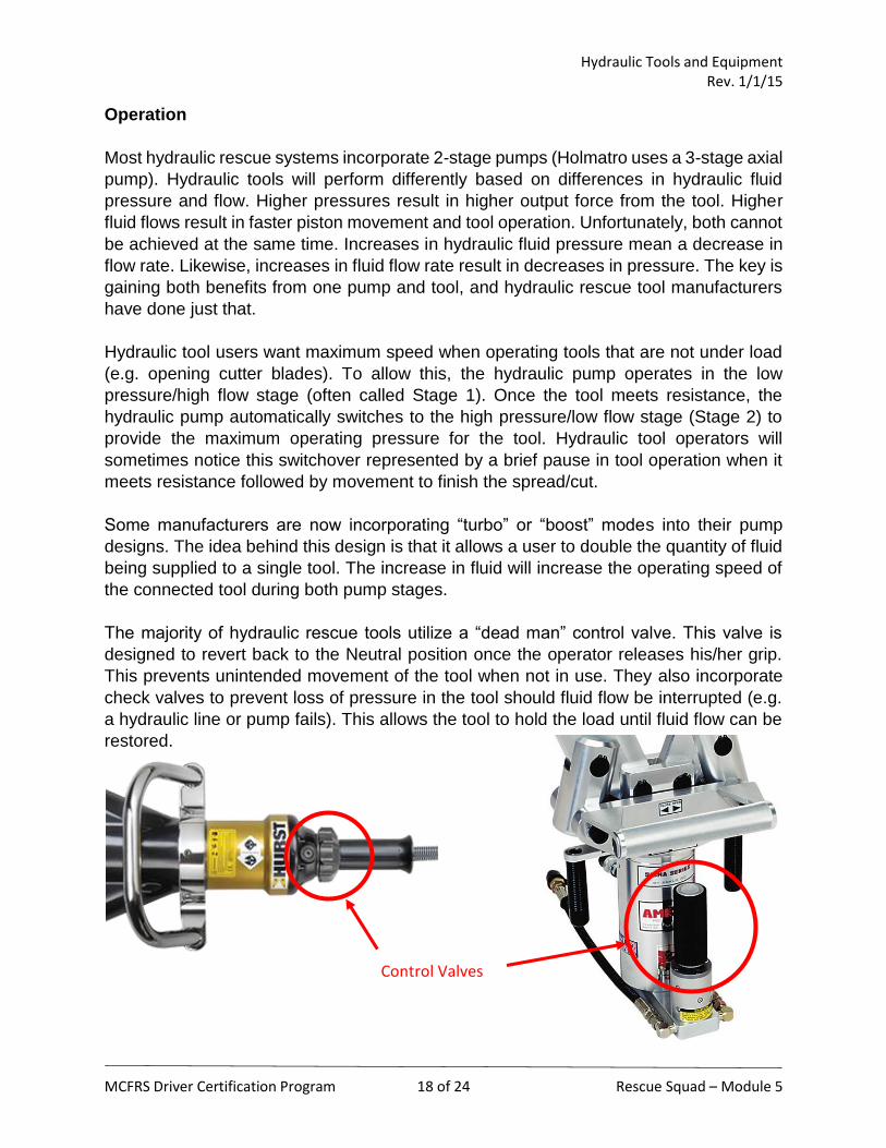
The majority of hydraulic rescue tools utilize a “dead man” control valve. This valve is
designed to revert back to the Neutral position once the operator releases his/her grip.
This prevents unintended movement of the tool when not in use. They also incorporate
check valves to prevent loss of pressure in the tool should fluid flow be interrupted (e.g.
a hydraulic line or pump fails). This allows the tool to hold the load until fluid flow can be
restored.
Control Valves

Hydraulic Tools and Equipment Rev. 1/1/15
MCFRS Driver Certification Program 19 of 24 Rescue Squad – Module 5
Spreaders
Spreaders use a set of arms connected to a piston rod to apply
outward force at the tip of each arm. They can be used for prying
and spreading as well as lifting. Spreaders come in different sizes
with varying arm lengths. Longer arms provide greater spreading
distance at full opening. However, this typically results in a
decrease in maximum spreading force.
Spreaders utilize a double acting cylinder so force is applied to the
arms as they are both opening and closing. This closing force can
be used to pull and pinch objects. One thing to note is that the
closing force will be less than the opening force. This is due to the
fact that the surface area of the piston is not equal on both sides.
The double acting cylinder example from earlier in the module
shows this difference.
There are a variety of different spreader tip designs
and accessories. Some tips are designed for gripping
surfaces while others are used for peeling. Many tips
have holes drilled through them for mounting chains to
be used in pulling applications.
Whenever spreading, it is important to obtain a good grip with the tips. Spreading should
ONLY be done at the tips – using the arms of the tool will result in damage.
“Maximum spreading force” is often advertised by manufacturers to promote their tools.
However, one problem with these numbers is that they are obtained by the individual
manufacturers who do not necessarily use the same test methods as other
manufacturers. To help remedy this issue, NFPA 1936 – Standard on Powered Rescue
Tools outlines specific testing guidelines for NFPA-compliant rescue tools.

Hydraulic Tools and Equipment Rev. 1/1/15
MCFRS Driver Certification Program 20 of 24 Rescue Squad – Module 5
Spreaders (continued)
In this test, the holes used for pulling attachments provide the test points. The spreading
force exerted by the tool is measured at 10 uniformly spaced intervals that range from the
fully closed position to 95% of the fully open position. The measured forces are then
converted to a value for force at the tool tip using a specified calculation. The lowest
calculated spreading force of all 10 test points is designated as the LSF (Lowest
Spreading Force) for that tool. The highest calculated spreading force of all 10 test points
is designated as the HSF (Highest Spreading Force) for the tool. The test is then
conducted for pulling force, yielding LPF and HPF values.
Cutters
Cutters act as hydraulic scissors to cut
through various metals. Similar to
spreader arms, cutters contain two
pivoting cutting blades connected to a
piston rod. The design of the cutter
blades dictate the size, shape and
strength of materials that can be cut.
Although cutters also utilized double acting cylinders, they are not designed for use in
both directions. Their sole function is to cut. The greatest cutting capacity is achieved
when the cut is performed as close to the blades pivot point as possible (often referred to
as the “notch”). Also, to avoid damage, the cutting blades should be positioned at 90° to
the object to be cut.

Hydraulic Tools and Equipment Rev. 1/1/15
MCFRS Driver Certification Program 21 of 24 Rescue Squad – Module 5
NFPA 1936 also provides testing procedures and ratings for cutters.
In this test, the cutter is tested with six different types of material. It
is assigned a rating based on the thickness of material that it is able
to completely sever in a single continuous motion. To be NFPA
compliant, the cutter must complete a minimum of 60 qualified cuts.
An example of a NFPA cutter rating would be A7/B9/C7/D8/E9.
Combination Tools
Combination tools are hybrids of a spreader and cutter. They are designed to be a
multifunctional tool with both spreading and cutting capabilities. Combination tools may
not provide the optimum performance of a job-specific tool like a spreader or cutter, but
they offer flexibility and extrication options in an all-in-one
package. As with spreaders and cutters, combination tools are
equipped with various sizes and designs of blades.
To be NFPA compliant, combination tools must undergo testing as
both a spreader AND a cutter. Therefore, it will carry both sets of
ratings.

Hydraulic Tools and Equipment Rev. 1/1/15
MCFRS Driver Certification Program 22 of 24 Rescue Squad – Module 5
Rams
Rams are used for pushing and/or pulling. Unlike spreaders that using pivoting arms,
rams utilize only the piston rod to apply linear force. Rams come in a variety of lengths to
meet different applications.
Some rams utilize double acting hydraulic cylinders to apply both pushing and pulling
force. As mentioned previously, the double acting cylinder will apply more force in one
direction. In the case of a ram, the largest force is applied during the push. Pulling force
is approximately 50% of the pushing force due to the reduction in surface area on the
opposite side of the piston.
Some rams come with attachments for additional functionality. Different bases and tips
provide either grip or piecing/cutting capabilities. Ram extensions can also be used to
increase the range of the ram.
The NFPA 1936 testing procedure for rams is similar to that for spreaders. The spreading
force exerted by the ram is measured at 3 uniformly spaced intervals between the fully
retracted position and 95% of the fully extended position. The recorded values will be
used to determine the spreading forces, HSF and LSF. If the ram is capable of pulling,
the test will be repeated to determine HPF and LPF values.

Hydraulic Tools and Equipment Rev. 1/1/15
MCFRS Driver Certification Program 23 of 24 Rescue Squad – Module 5
Another type of ram is the telescoping ram. The 2-stage telescoping action of these rams
provide the benefit of increased stroke length while maintaining a relatively small retracted
storage length. The 1st stage of extension provides the maximum pushing capacity.
Capacity decreases as the 2nd stage engages because the second piston has less surface
area than the combination of both pistons in the 1st stage.
Telescoping rams are only designed for pushing. They undergo the same testing
requirements as other rams to achieve NFPA compliance.
Hurst Lift Cylinders
The Hurst telescopic lifting cylinders are a type of
specialized hydraulic rescue tool. They operate much
like a telescoping bottle jack. However, instead of being
powered by a hand pump, the Hurst lift cylinders are
powered by the Hurst hydraulic system. The higher
operating pressures lead to high lifting capacities. Lift
cylinders operating on a 5,000 psi system have
maximum capacities of just over 96,000 lbs. while cylinders on a 10,000 psi system top
out at over 141,500 lbs.
The narrow profile of Hurst lift cylinders make
them perfect for applications where large high
pressure air bags may not fit (e.g. under rail and
METRO cars). The lift cylinders come in 2- and 3-
piston models. Numerous attachments and
accessories are included with a lift cylinder setup.
Hurst lift cylinder operation is more complicated
than that of standard hydraulic rescue tools.
Proper training from a qualified instructor is highly
recommended before use.
Hydraulic Tools and Equipment Rev. 1/1/15
MCFRS Driver Certification Program 24 of 24 Rescue Squad – Module 5
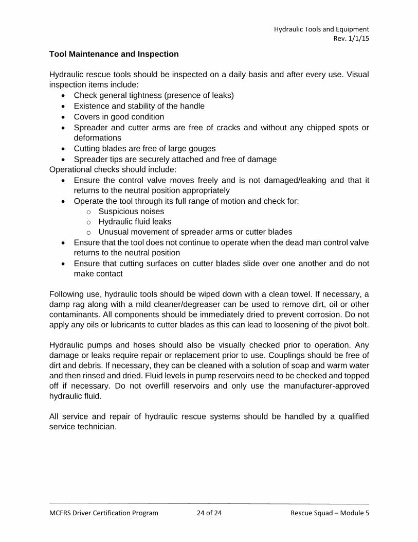
Tool Maintenance and Inspection
Hydraulic rescue tools should be inspected on a daily basis and after every use. Visual
inspection items include:
Check general tightness (presence of leaks)
Existence and stability of the handle
Covers in good condition
Spreader and cutter arms are free of cracks and without any chipped spots or
deformations
Cutting blades are free of large gouges
Spreader tips are securely attached and free of damage
Operational checks should include:
Ensure the control valve moves freely and is not damaged/leaking and that it
returns to the neutral position appropriately
Operate the tool through its full range of motion and check for:
o Suspicious noises
o Hydraulic fluid leaks
o Unusual movement of spreader arms or cutter blades
Ensure that the tool does not continue to operate when the dead man control valve
returns to the neutral position
Ensure that cutting surfaces on cutter blades slide over one another and do not
make contact
Following use, hydraulic tools should be wiped down with a clean towel. If necessary, a
damp rag along with a mild cleaner/degreaser can be used to remove dirt, oil or other
contaminants. All components should be immediately dried to prevent corrosion. Do not
apply any oils or lubricants to cutter blades as this can lead to loosening of the pivot bolt.
Hydraulic pumps and hoses should also be visually checked prior to operation. Any
damage or leaks require repair or replacement prior to use. Couplings should be free of
dirt and debris. If necessary, they can be cleaned with a solution of soap and warm water
and then rinsed and dried. Fluid levels in pump reservoirs need to be checked and topped
off if necessary. Do not overfill reservoirs and only use the manufacturer-approved
hydraulic fluid.
All service and repair of hydraulic rescue systems should be handled by a qualified
service technician.