Embed Size (px)
Citation preview
Hydraulic Structures - Comparison Of Gully Flow Due To Different Gully Outlets
by Md. Nazmul Azim Beg1,2, Rita F. Carvalho1,2 and Jorge Leandro2,3
1Department of Civil Engineering, University of Coimbra, Portugal,2MARE – Marine and Environmental Sciences Centre, Portugal
3Technical University of Munich, Munich, Germany
QUICS - Quantifying Uncertainty in Integrated Catchment Studies, European Union’s Seventh Framework Programme for research, technological development and demonstration
ConclusionIntroduction Methodology Results
by Nazmul A. Beg, Rita F. Carvalho, J. Leandro
IntroductionAim
• An urban drainage system flow depends on the surface and the sewer network as well as on their linking elements.
• Gullies are common elements in an urban drainage system which collect runoff from roadside curbs and conveys it to the buried drainage system - accurate prediction of discharge capacity of a gully is important as it decides the amount of flow between surface and underground drainage network Different types of gully outlets may have different discharge capacities due to its size and positioning; which often ignored in preparing a flood routing model
• OpenFOAM® CFD modelling toolbox with the solver interFoam that includes Volume of Fluid (VOF) method is able to simulate this kind of flows
Hydraulic StructuresComparison Of Gully Flow Due To Different Gully Outlets
ConclusionIntroduction Methodology Results
by Nazmul A. Beg, Rita F. Carvalho, J. Leandro
Introductionobjective
• simulate numerically the hydraulic performance of a gully, sizing 0.6 m × 0.24 m × 0.32 m (L × W × D) connected below a 0.5 m wide rectangular channel and draining to a manhole of 1 m diameter.
• validate model simulation with data from Dual Drainage Multiple Linking Element experimental installation located at the Laboratory of Hydraulics of the University of Coimbra.
• investigate flow hydraulics, flow efficiency and discharge coefficient of the gully for different gully outlet pipes.
• find uncertainty in gully discharge coefficient due to different gully outlet geometry
Hydraulic StructuresComparison Of Gully Flow Due To Different Gully Outlets
ConclusionMethodology ResultsIntroduction
by Nazmul A. Beg, Rita F. Carvalho, J. Leandro
Methodology
Hydraulic StructuresComparison Of Gully Flow Due To Different Gully Outlets
• A validated methodology is adapted from Beg et al. (2017)
• Replication of experimental real scale facility at University of Coimbra containing a surface drain, a gully and a manhole
• Comparison of point velocity at the gully
• Comparison of surcharge and discharge level at the manhole
ConclusionIntroduction Methodology Results
by Nazmul A. Beg, Rita F. Carvalho, J. Leandro
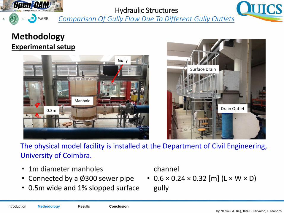
MethodologyExperimental setup
Hydraulic StructuresComparison Of Gully Flow Due To Different Gully Outlets
Manhole
0.3m
• 1m diameter manholes• Connected by a Ø300 sewer pipe• 0.5m wide and 1% slopped surface
channel • 0.6 × 0.24 × 0.32 [m] (L × W × D)
gully
Gully
The physical model facility is installed at the Department of Civil Engineering, University of Coimbra.
Surface Drain
Drain Outlet
ConclusionIntroduction ResultsMethodology
by Nazmul A. Beg, Rita F. Carvalho, J. Leandro
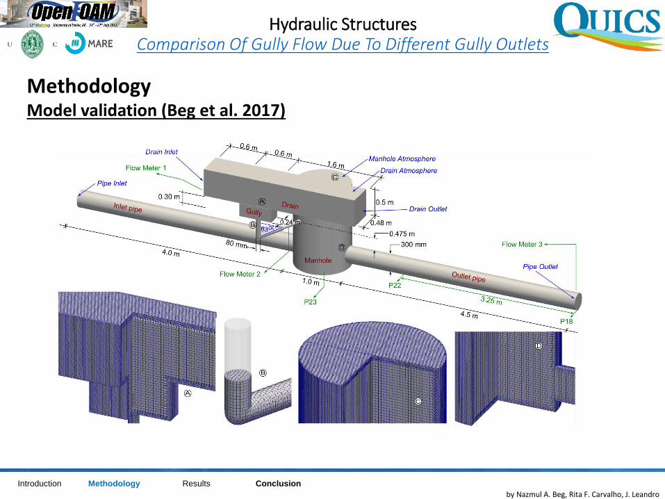
MethodologyModel validation (Beg et al. 2017)
Hydraulic StructuresComparison Of Gully Flow Due To Different Gully Outlets
ConclusionIntroduction ResultsMethodology
by Nazmul A. Beg, Rita F. Carvalho, J. Leandro
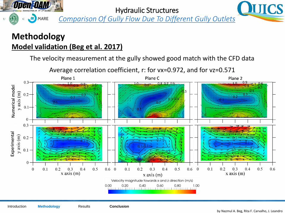
MethodologyModel validation (Beg et al. 2017)
Hydraulic StructuresComparison Of Gully Flow Due To Different Gully Outlets
The velocity measurement at the gully showed good match with the CFD data
Average correlation coefficient, r: for vx=0.972, and for vz=0.571
ConclusionIntroduction ResultsMethodology
by Nazmul A. Beg, Rita F. Carvalho, J. Leandro
MethodologyModel validation (Beg et al. 2017)
Hydraulic StructuresComparison Of Gully Flow Due To Different Gully Outlets
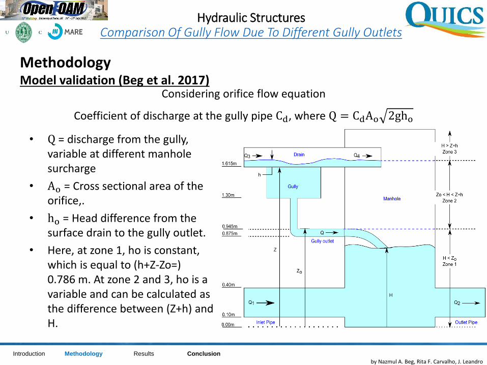
Considering orifice flow equation
Coefficient of discharge at the gully pipe Cd, where Q = CdAo 2gho
• Q = discharge from the gully, variable at different manhole surcharge
• Ao = Cross sectional area of the orifice,.
• ho = Head difference from the surface drain to the gully outlet.
• Here, at zone 1, ho is constant, which is equal to (h+Z-Zo=) 0.786 m. At zone 2 and 3, ho is a variable and can be calculated as the difference between (Z+h) and H.
ConclusionIntroduction ResultsMethodology
by Nazmul A. Beg, Rita F. Carvalho, J. Leandro
MethodologyModel validation (Beg et al. 2017)
Hydraulic StructuresComparison Of Gully Flow Due To Different Gully Outlets
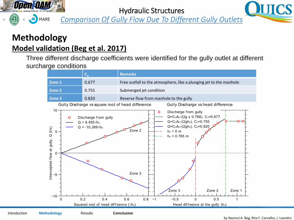
Cd Remarks
Zone 1 0.677 Free outfall to the atmosphere, like a plunging jet to the manhole
Zone 2 0.755 Submerged jet condition
Zone 3 0.820 Reverse flow from manhole to the gully
Three different discharge coefficients were identified for the gully outlet at different
surcharge conditions
ConclusionIntroduction ResultsMethodology
by Nazmul A. Beg, Rita F. Carvalho, J. Leandro
MethodologyNumerical Model set up
Hydraulic StructuresComparison Of Gully Flow Due To Different Gully Outlets
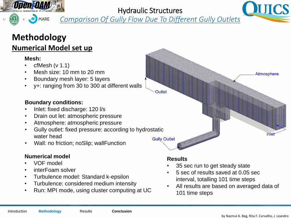
Mesh:
• cfMesh (v 1.1)
• Mesh size: 10 mm to 20 mm
• Boundary mesh layer: 5 layers
• y+: ranging from 30 to 300 at different walls
Boundary conditions:
• Inlet: fixed discharge: 120 l/s
• Drain out let: atmospheric pressure
• Atmosphere: atmospheric pressure
• Gully outlet: fixed pressure: according to hydrostatic
water head
• Wall: no friction; noSlip; wallFunction
Numerical model
• VOF model
• interFoam solver
• Turbulence model: Standard k-epsilon
• Turbulence: considered medium intensity
• Run: MPI mode, using cluster computing at UC
Results
• 35 sec run to get steady state
• 5 sec of results saved at 0.05 sec
interval, totalling 101 time steps
• All results are based on averaged data of
101 time steps
ConclusionIntroduction ResultsMethodology
by Nazmul A. Beg, Rita F. Carvalho, J. Leandro
MethodologyNumerical Model set up
Hydraulic StructuresComparison Of Gully Flow Due To Different Gully Outlets
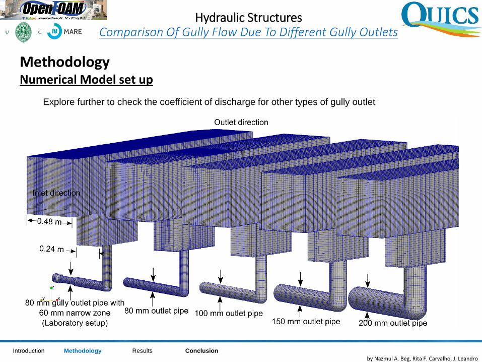
Explore further to check the coefficient of discharge for other types of gully outlet
ConclusionIntroduction ResultsMethodology

by Nazmul A. Beg, Rita F. Carvalho, J. Leandro
ResultsVelocity at different gully
Hydraulic StructuresComparison Of Gully Flow Due To Different Gully Outlets
(m/s)
• In smaller diameter of outlet
pipes, high velocity zone is
concentrated at smaller area:
which is at the same side of the
inlet
• In a bigger diameter outlet pipe,
the high velocity zone is moved
towards the centre
• Ratio of effective area becomes
larger in bigger diameter outket
ConclusionIntroduction Methodology Results
by Nazmul A. Beg, Rita F. Carvalho, J. Leandro
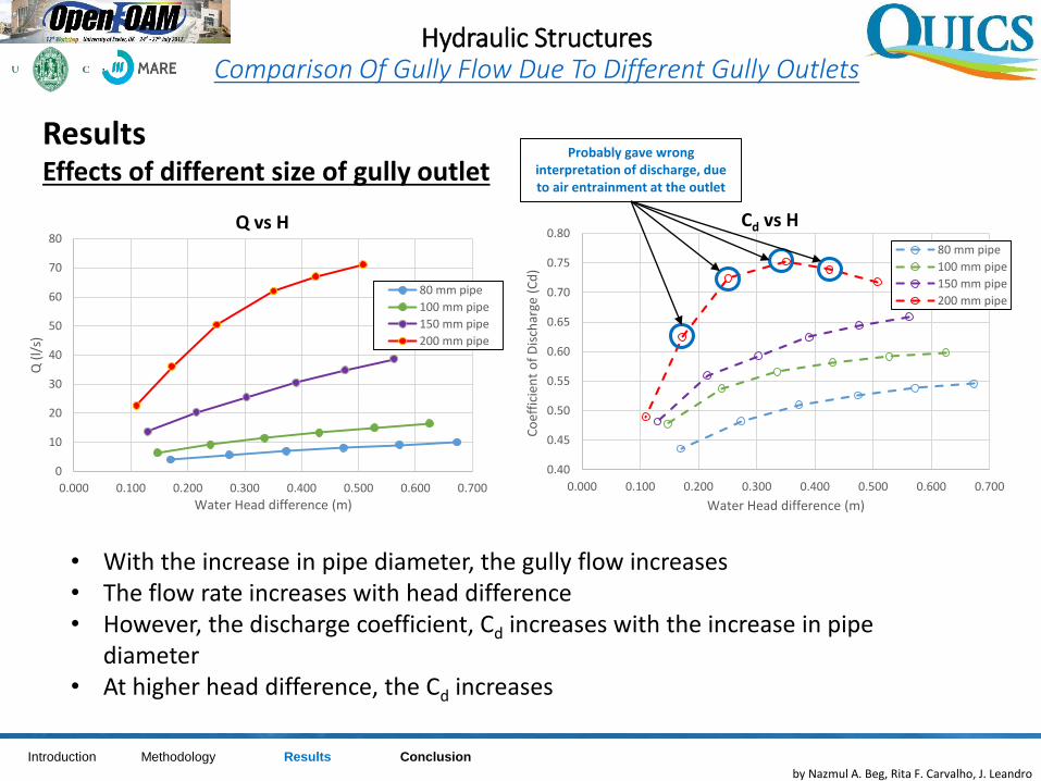
ResultsEffects of different size of gully outlet
Hydraulic StructuresComparison Of Gully Flow Due To Different Gully Outlets
0
10
20
30
40
50
60
70
80
0.000 0.100 0.200 0.300 0.400 0.500 0.600 0.700
Q (
l/s)
Water Head difference (m)
Q vs H
80 mm pipe
100 mm pipe
150 mm pipe
200 mm pipe
0.40
0.45
0.50
0.55
0.60
0.65
0.70
0.75
0.80
0.000 0.100 0.200 0.300 0.400 0.500 0.600 0.700
Co
effi
cien
t o
f D
isch
arge
(C
d)
Water Head difference (m)
Cd vs H
80 mm pipe
100 mm pipe
150 mm pipe
200 mm pipe
• With the increase in pipe diameter, the gully flow increases• The flow rate increases with head difference• However, the discharge coefficient, Cd increases with the increase in pipe
diameter• At higher head difference, the Cd increases
Probably gave wrong interpretation of discharge, due to air entrainment at the outlet
ConclusionIntroduction Methodology Results
by Nazmul A. Beg, Rita F. Carvalho, J. Leandro
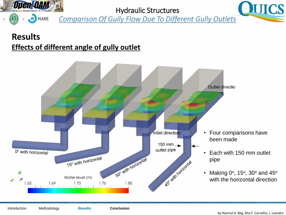
ResultsEffects of different angle of gully outlet
Hydraulic StructuresComparison Of Gully Flow Due To Different Gully Outlets
• Four comparisons have
been made
• Each with 150 mm outlet
pipe
• Making 0o, 15o, 30o and 45o
with the horizontal direction
ConclusionIntroduction Methodology Results
by Nazmul A. Beg, Rita F. Carvalho, J. Leandro
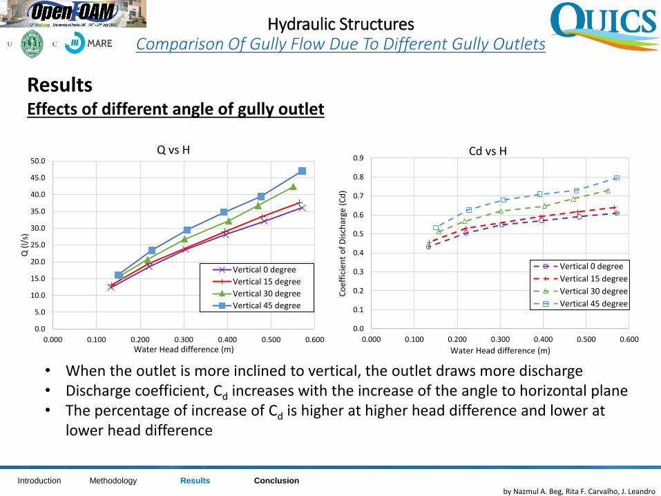
ResultsEffects of different angle of gully outlet
Hydraulic StructuresComparison Of Gully Flow Due To Different Gully Outlets
• When the outlet is more inclined to vertical, the outlet draws more discharge• Discharge coefficient, Cd increases with the increase of the angle to horizontal plane• The percentage of increase of Cd is higher at higher head difference and lower at
lower head difference
ConclusionIntroduction Methodology Results
0.0
5.0
10.0
15.0
20.0
25.0
30.0
35.0
40.0
45.0
50.0
0.000 0.100 0.200 0.300 0.400 0.500 0.600
Q (
l/s)
Water Head difference (m)
Q vs H
Vertical 0 degree
Vertical 15 degree
Vertical 30 degree
Vertical 45 degree
0.0
0.1
0.2
0.3
0.4
0.5
0.6
0.7
0.8
0.9
0.000 0.100 0.200 0.300 0.400 0.500 0.600C
oef
fici
ent
of
Dis
char
ge (
Cd
)Water Head difference (m)
Cd vs H
Vertical 0 degree
Vertical 15 degree
Vertical 30 degree
Vertical 45 degree
by Nazmul A. Beg, Rita F. Carvalho, J. Leandro
Conclusion
Hydraulic StructuresComparison Of Gully Flow Due To Different Gully Outlets
• A real scale gully model was made using OpenFOAM
• The model methodology was validated at Beg at al. (2017)
• Discharge coefficient was checked from different size and position of gully
outlet pipe
• Larger outlet pipes showed higher discharge coefficient compared to
smaller outlet pipes
• Gully outlet having different angles with the horizontal showed different
discharge coefficients
• The uncertainty in the gully discharge coefficient will be quantified at a
latter stage of the research
ConclusionIntroduction Methodology Results
by Nazmul A. Beg, Rita F. Carvalho, J. Leandro
Thank you for your attention
Hydraulic StructuresComparison Of Gully Flow Due To Different Gully Outlets
Md Nazmul Azim Beg: [email protected]. Rita F. Carvalho: [email protected]
ConclusionIntroduction Methodology Results

Partners and Acknowledgements
This project has received funding from the European Union’s Seventh FrameworkProgramme for research, technological development and demonstration under grantagreement no 607000.
www.quics.eu