Embed Size (px)
Citation preview
312350L
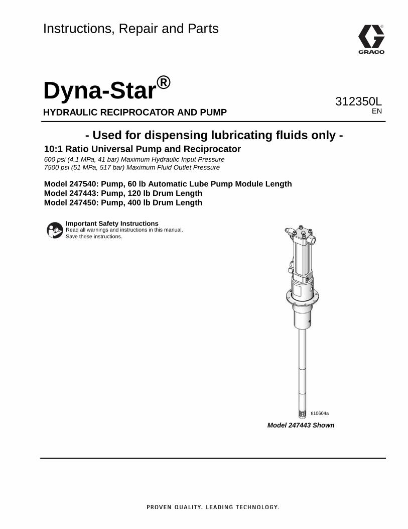
Instructions, Repair and Parts
Dyna-Star®HYDRAULIC RECIPROCATOR AND PUMP
- Used for dispensing lubricating fluids only - 10:1 Ratio Universal Pump and Reciprocator600 psi (4.1 MPa, 41 bar) Maximum Hydraulic Input Pressure7500 psi (51 MPa, 517 bar) Maximum Fluid Outlet Pressure
Model 247540: Pump, 60 lb Automatic Lube Pump Module LengthModel 247443: Pump, 120 lb Drum LengthModel 247450: Pump, 400 lb Drum Length
Important Safety InstructionsRead all warnings and instructions in this manual. Save these instructions.
ti10604a
Model 247443 Shown
EN
Warnings
2 312350L
WarningsThe following warnings are for the setup, use, grounding, maintenance, and repair of this equipment. The exclama-tion point symbol alerts you to a general warning and the hazard symbols refer to procedure-specific risks. When these symbols appear in the body of this manual or on warning labels, refer back to these Warnings. Product-specific hazard symbols and warnings not covered in this section may appear throughout the body of this manual where applicable.
WARNINGFIRE AND EXPLOSION HAZARD When flammable fluids are present in the work area, such as gasoline and windshield wiper fluid, be aware that flammable fumes can ignite or explode. To help prevent fire and explosion:• Use equipment only in well ventilated area.• Eliminate all ignition sources, such as cigarettes and portable electric lamps. • Keep work area free of debris, including rags and spilled or open containers of solvent and gasoline.• Do not plug or unplug power cords or turn lights on or off when flammable fumes are present.• Ground all equipment in the work area.• Use only grounded hoses.• Stop operation immediately if static sparking occurs or you feel a shock. Do not use equipment
until you identify and correct the problem.• Keep a working fire extinguisher in the work area.
EQUIPMENT MISUSE HAZARDMisuse can cause death or serious injury.• Do not operate the unit when fatigued or under the influence of drugs or alcohol.• Do not exceed the maximum working pressure or temperature rating of the lowest rated system
component. See Technical Data in all equipment manuals.• Use fluids and solvents that are compatible with equipment wetted parts. See Technical Data in all
equipment manuals. Read fluid and solvent manufacturer’s warnings. For complete information about your material, request MSDS from distributor or retailer.
• Turn off all equipment and follow the Pressure Relief Procedure when equipment is not in use.• Check equipment daily. Repair or replace worn or damaged parts immediately with genuine manu-
facturer’s replacement parts only.• Do not alter or modify equipment. Alterations or modifications may void agency approvals and create
safety hazards.• Make sure all equipment is rated and approved for the environment in which you are using it.• Use equipment only for its intended purpose. Call your distributor for information.• Route hoses and cables away from traffic areas, sharp edges, moving parts, and hot surfaces.• Do not kink or over bend hoses or use hoses to pull equipment.• Keep children and animals away from work area.• Comply with all applicable safety regulations.
Warnings
312350L 3
+
SKIN INJECTION HAZARD High-pressure fluid from dispensing device, hose leaks, or ruptured components will pierce skin. This may look like just a cut, but it is a serious injury that can result in amputation. Get immediate surgical treatment.• Do not point dispensing device at anyone or at any part of the body.• Do not put your hand over the fluid outlet.• Do not stop or deflect leaks with your hand, body, glove, or rag.• Follow the Pressure Relief Procedure when you stop dispensing and before cleaning, checking, or
servicing equipment. • Tighten all fluid connections before operating the equipment.• Check hoses and couplings daily. Replace worn or damaged parts immediately.
MOVING PARTS HAZARDMoving parts can pinch, cut or amputate fingers and other body parts.• Keep clear of moving parts.• Do not operate equipment with protective guards or covers removed.• Pressurized equipment can start without warning. Before checking, moving, or servicing equipment,
follow the Pressure Relief Procedure and disconnect all power sources.
BURN HAZARD Equipment surfaces and fluid that is heated can become very hot during operation. To avoid severe burns:• Do not touch hot fluid or equipment.
TOXIC FLUID OR FUMES HAZARD Toxic fluids or fumes can cause serious injury or death if splashed in the eyes or on skin, inhaled, or swallowed.• Read MSDSs to know the specific hazards of the fluids you are using.• Store hazardous fluid in approved containers, and dispose of it according to applicable guidelines.
PERSONAL PROTECTIVE EQUIPMENTWear appropriate protective equipment when in the work area to help prevent serious injury, including eye injury, hearing loss, inhalation of toxic fumes, and burns. This protective equipment includes but is not limited to:• Protective eyewear, and hearing protection. • Respirators, protective clothing, and gloves as recommended by the fluid and solvent manufacturer.
WARNING
Installation
4 312350L
Installation
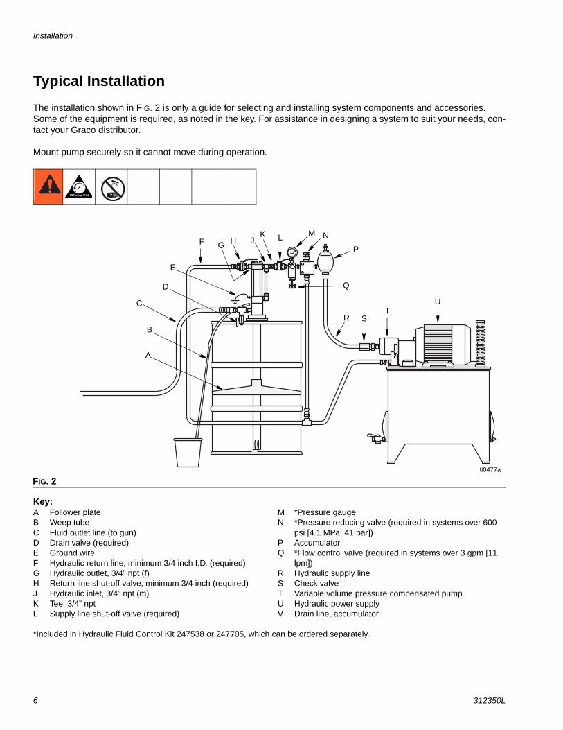
Pump AccessoriesNOTE: The reference letters in the following descrip-tions, refer to the reference letters used in FIG. 2, page 6.
Follower Plate (A): Place follower plate on grease and rotate while pressing firmly to level material. Order part number 247700 for 60# and 90# automatic lube pump modules; 247701 for 120# refinery reservoir; or 247702 for 400# refinery reservoir.
Pump Outlet Drain Valve (D): Helps relieve fluid pres-sure in pump when pump is shut off. Install valve close to pump fluid outlet. Order valve, Part No. 111229.
A pump outlet drain (D) is required in your system. This valve helps relieve pressure in the displacement pump and hose when shutting down system and in case of a clogged outlet hose. Install valve close to pump outlet.
Hydraulic Power SupplySee FIG. 2. page 6.
The hydraulic power supply system (U) must have a pressure reducing valve and a pressure-compensated flow control. A flow control valve (Q) is required to limit the incoming flow to the reciprocator to a maximum of 3 gpm (11 lpm).
Hydraulic LinesShut-off Valves (H, L): Installed on the hydraulic supply and return lines. Order Part No. 108537 and 112578.
Drain Line: Monitor the weepage of hydraulic fluid or lubricant. If it seems excessive or increases suddenly, the reciprocator/pump seals may need to be changed.
Hoses: Use a minimum 1/2 inch supply line (R) and minimum 3/4 inch return line (F) on the reciprocator. Contact your Graco representative for line sizing.
Pressure Reducing Valve (N): Circulates excess hydraulic fluid pressure back to the hydraulic power sup-ply. Install this valve (N) in the hydraulic supply line with a drain hose (W) teed into the hydraulic return line (F). Limit supply pressure to a maximum 600 psi (4.1 MPa, 41 bar).
Accumulator (P): Reduces hammering effect caused by the motor when it reverses direction.
Fluid-filled Pressure Gauge (M), Part No. 112567: Monitors hydraulic pressure to the reciprocator during startup. See FIG. 2. Use the gauge for initial adjustment of the reciprocator. It can be removed after adjustment.
NOTE: Pressure gauge (M), pressure reducing valve (N) and a flow control valve (Q) are included in the Hydraulic Fluid Control Kit 247538 or 247705, which can be ordered separately.
Maximum Working Pressure of Accessories
To reduce the risk of serious injury including fluid injec-tion and splashing in the eyes or on the skin which may be caused if component ruptures, all accessories added to the reciprocator power supply side must have at least 600 psi (4.1 MPa, 41 bar) maximum working pressure.
All accessories added to the pump fluid outlet side must have at least 7500 psi (51 MPa, 517 bar) maxi-mum working pressure.
Limit Fluid Flow to Reciprocator
To reduce the risk of overpressurizing the hydraulic reciprocator which could cause a rupture and serious injury, including fluid injection, a hydraulic system must have a means to limit the incoming fluid flow to the reciprocator to a maximum of 3 gpm (11 lpm) and 600 psi (4.1 MPa, 41 bar). See description below.
Installation
312350L 5
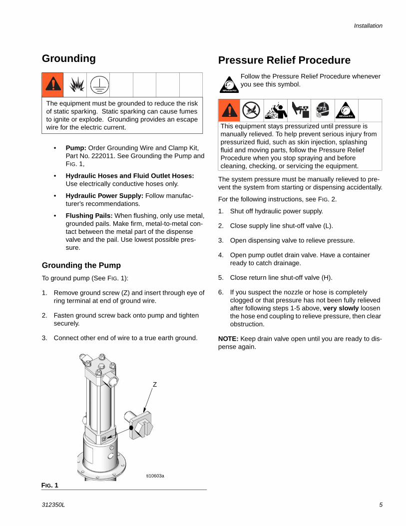
Grounding
• Pump: Order Grounding Wire and Clamp Kit, Part No. 222011. See Grounding the Pump and FIG. 1,
• Hydraulic Hoses and Fluid Outlet Hoses: Use electrically conductive hoses only.
• Hydraulic Power Supply: Follow manufac-turer’s recommendations.
• Flushing Pails: When flushing, only use metal, grounded pails. Make firm, metal-to-metal con-tact between the metal part of the dispense valve and the pail. Use lowest possible pres-sure.
Grounding the Pump
To ground pump (See FIG. 1):
1. Remove ground screw (Z) and insert through eye of ring terminal at end of ground wire.
2. Fasten ground screw back onto pump and tighten securely.
3. Connect other end of wire to a true earth ground.
Pressure Relief ProcedureFollow the Pressure Relief Procedure whenever you see this symbol.
The system pressure must be manually relieved to pre-vent the system from starting or dispensing accidentally.
For the following instructions, see FIG. 2.
1. Shut off hydraulic power supply.
2. Close supply line shut-off valve (L).
3. Open dispensing valve to relieve pressure.
4. Open pump outlet drain valve. Have a container ready to catch drainage.
5. Close return line shut-off valve (H).
6. If you suspect the nozzle or hose is completely clogged or that pressure has not been fully relieved after following steps 1-5 above, very slowly loosen the hose end coupling to relieve pressure, then clear obstruction.
NOTE: Keep drain valve open until you are ready to dis-pense again.
The equipment must be grounded to reduce the risk of static sparking. Static sparking can cause fumes to ignite or explode. Grounding provides an escape wire for the electric current.
FIG. 1
Z
ti10603a
This equipment stays pressurized until pressure is manually relieved. To help prevent serious injury from pressurized fluid, such as skin injection, splashing fluid and moving parts, follow the Pressure Relief Procedure when you stop spraying and before cleaning, checking, or servicing the equipment.
Installation
6 312350L
Typical Installation
The installation shown in FIG. 2 is only a guide for selecting and installing system components and accessories. Some of the equipment is required, as noted in the key. For assistance in designing a system to suit your needs, con-tact your Graco distributor.
Mount pump securely so it cannot move during operation.
Key:A Follower plateB Weep tubeC Fluid outlet line (to gun)D Drain valve (required)E Ground wireF Hydraulic return line, minimum 3/4 inch I.D. (required)G Hydraulic outlet, 3/4” npt (f)H Return line shut-off valve, minimum 3/4 inch (required)J Hydraulic inlet, 3/4” npt (m)K Tee, 3/4” nptL Supply line shut-off valve (required)
M *Pressure gaugeN *Pressure reducing valve (required in systems over 600
psi [4.1 MPa, 41 bar])P AccumulatorQ *Flow control valve (required in systems over 3 gpm [11
lpm])R Hydraulic supply lineS Check valveT Variable volume pressure compensated pumpU Hydraulic power supplyV Drain line, accumulator
*Included in Hydraulic Fluid Control Kit 247538 or 247705, which can be ordered separately.
FIG. 2ti0477a
UT
SR
Q
P
NMLKJHGF
D
C
B
A
E
Operation
312350L 7
Operation
Before Starting Pump• Check hydraulic fluid level in hydraulic power supply
before each use. Add fluid as necessary to fill the lines.
• Flush pump before using it for the first time to remove the light oil that was left in after factory test-ing to protect pump from corrosion. Be sure solvent used is compatible with the fluid to be pumped and the pump’s wetted parts. See Technical Data, page 26. Flush until clean solvent comes out of hose.
Starting PumpFor the following instructions, see FIG. 2.
1. Turn on hydraulic power supply.
2. Open return line shut-off valve (H) first, then slowly open the hydraulic supply shut-off valve (L).
3. Adjust flow control valve (Q) to limit the hydraulic flow to no more than 3 gpm (11 lpm), which is approximately 60 cycles per minute.
4. Adjust pressure reducing valve (N) to increase hydraulic inlet pressure from 50 to 600 psi (0.34 to 4.1 MPa, 3.4 to 41 bar).
• Increasing inlet pressure, increases outlet pres-sure.
• Decreasing inlet pressure, decreases outlet pressure.
5. Open drain valve while priming pump.
6. When pump is primed, close drain valve.
ShutdownRelieve pressure, page 5, whenever you shutdown.
NOTICETo prevent damage to pump, do not operate pump without it being securely mounted to a drum cover or support.
COMPONENT RUPTURE HAZARD
Overpressurizing any component can result in serious injury or property damage as a result of rupture, fire, and/or explosion.The maximum working pressure of each component in the system may not be the same. To reduce the risk of overpressurizing any component in the system:
• Be sure you know the maximum working pressure of each component.
• Never exceed the maximum working pressure of the lowest rated component in the system.
• Do not exceed the maximum pump cycle rate.
• The pump has a rated ratio of 10:1. However, it is capable of reaching stall pressures equal to 12.5 times the hydraulic input pressure. To calculate the fluid output pressure, multiply the hydraulic pressure shown on the hydraulic control module gauge by 12.5.
For example:
600 psi hydraulic x 12.5 = 7500 psi fluid output
4.14 MPa hydraulic x 12.5 = 51.8 MPa fluid output
41.4 bar hydraulic x 12.5 = 5.18 bar fluid output
• Regulate hydraulic pressure to the pump so that no fluid line component or accessory is overpressurized.
NOTICEAlways use lowest pressure possible to obtain desired results. This reduces pump wear.
Maximum Working Pressures
To reduce the risk of serious injury, including fluid injection and splashing in the eyes or on the skin, which may be caused if a component ruptures:
• Never exceed 600 psi (4.1 MPa, 41 bar) Maximum Hydraulic Pressure to the reciprocator.
• Never exceed 7500 psi (51 MPa, 517 bar) Maximum Outlet Pressure from the displacement pump.
• Accessories added to the pump fluid outlet side should have at least a 7500 psi (51 MPa, 517 bar) Maximum Working Pressure.
• Read and understand COMPONENT RUPTURE HAZARD instructions, page 7.
Troubleshooting
8 312350L
Troubleshooting
Problem Cause Solution
Pump does not run. Closed dispense valve. Pump only runs with valve open.
Pressure too low. Increase supply pressure using a pressure adjusting valve.
Insufficient hydraulic fluid supply. Check hydraulic supply. Adjust to a maximum of 3 gpm (11 lpm) flow.
Clogged fluid outlet line, intake valve, dispense valve, suction line.
Relieve pressure, page 5. Check. Clear obstructions.
Reciprocator damaged. Repair.
Pump speeds up or runs erratically. Pump piston and/or intake valve worn.
Relieve pressure, page 5. Check and repair.
Empty supply container. Refill and repair. Do not allow pump to run dry. Monitor closely or use a low-level cutoff valve.
Pump runs but output low on up and/or down stroke.
Pump piston and/or intake valve worn.
Relieve pressure, page 5. Check and repair.
Pump run but output low on both up and down strokes.
Insufficient hydraulic fluid supply. Check hydraulic supply. Adjust to maximum 3 gpm (11 lpm) flow.
Pressure too low. Increase supply pressure using a pressure adjusting valve.
Clogged fluid outlet line, intake valve, dispense valve, suction line.
Relieve pressure, page 5. Check. Clear obstructions.
Excessive weepage from weep tube (B), page 4.
Worn throat packings. Repair.
Worn displacement seal. Repair.
Hydraulic oil leaks from fittings in the upper or lower reciprocator blocks (31, 32) [Parts page 23].
Fittings 1, 5, 58, (Parts, page 23), are loose, or their o-rings are worn or damaged.
Tighten the self-sealing fittings. If leaking persists, change o-rings.
Service
312350L 9
ServiceNOTE: The reference letters used in the following Ser-vice instructions refer to the Typical Installation illustra-tion provided on page 6.
The reference numbers used in the following Service instructions refer to the Parts pages beginning on page 23.
Pump Leaks at the Fluid Fittings
Tighten fittings (1, 5, 60; FIG. 3) which are self-sealing and have replaceable o-rings. If leaking persists, change o-rings.
Removing Displacement Pump from Reciprocator
Disassembly
1. Flush pump. Stop pump with displacement rod (35) (FIG. 4) in the lowest possible position.
2. Relieve pressure, page 5.
3. Disconnect fluid outlet hose (C) (FIG. 2, page 6) from displacement pump.
4. Slowly loosen hydraulic supply fitting (60) and return fitting (5) (FIG. 4). Remove hoses.
5. Install plugs in tube fittings and hose ends.
6. Clamp reciprocator/pump assembly in a vise.
FIG. 3
Use of a hydraulic power supply with fluid temperatures above 154°F (68°C) can create hot surfaces which can burn if touched.
• Do not touch pump, motor, or if hydraulic system fluid is above 154°F (68°C).
• Allow sufficient time for pump and motor to cool before attempting any service or repair.
sealingfitting (1, 5, 60)
reciprocator
o-ring(1a, 5a,60a)
ti04478 FIG. 4
336, 37
32
43
46(hiddenfrom view)
204
35
560
ti10602ati10610a
107
Service
10 312350L
7. Use a strap wrench on spacer tube (114) to unscrew it out of the pump adapter (8) and slide it down as far as it will go (FIG. 5).
8. Pull displacement rod (35) down as far as it will go. Remove pin (204) (FIG. 5).
9. Unscrew connecting rod (107) from displacement rod (35) (FIG. 5).
10. Clamp reciprocator in vise.
Replacing Throat Seals
NOTE: Replace throat seals if fluid leaks excessively through the weep tube (B), FIG. 2, page 6. This proce-dure can be done without disassembling entire recipro-cator.
Disassembly
1. Relieve pressure, page 5.
2. Disconnect reciprocator from displacement pump (see Removing Displacement Pump from Recipro-cator, page 9).
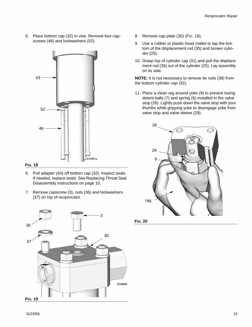
3. Remove four capscrews (15) and washers (27) from bottom of pump adapter (8). Tap pump adapter to loosen it and pull it off the motor housing (43) (FIG. 6).
FIG. 5
114
107
204
35
107
8
FIG. 6
15
27
8
43
Service
312350L 11
4. Remove retainer nut (11) and seal (44) from top of pump adapter (8).
5. Remove four capscrews (46) and washers (52) from bottom of motor housing (43) and remove motor housing from bottom cylinder cap (32).
6. Loosen nut (45a) on both ends of fluid tube (45) (FIG. 9).
7. Use a wrench to loosen elbow (1) and tee (60). Remove fluid tube (45). Install plug in each fitting to prevent contamination (FIG. 10).
FIG. 7
FIG. 8
11
44
8
46
43
32
16
52
FIG. 9
FIG. 10
45a
45a
45
60
1
45
Service
12 312350L
8. Check o-rings (1a and 60a) on fittings (1 and 60) and replace them if they are worn or damaged.
9. Remove capscrew (3), nut (36) and lockwashers (37). Remove the reciprocator cap plate (30).
10. Gently tap on bottom cylinder cap (32) to loosen cyl-inder cap from cylinder (25) using a rubber or plastic mallet.
NOTE: It is not necessary to remove the tie rods (38) from the bottom cylinder cap (32).
11. Remove seal (16) from bottom of cylinder cap (32).
Reassembly
Use Kit 247455. Use all new parts included in the kit.
1. Install seal (16) in bottom of cylinder cap (32) in the orientation shown in FIG. 13.
2. Reassemble cylinder cap (32) to motor housing (43). Install lock washers (52) and cap screws (46) (FIG. 13). Torque the capscrews to 28-32 ft-lb (38 to 43 N.m).
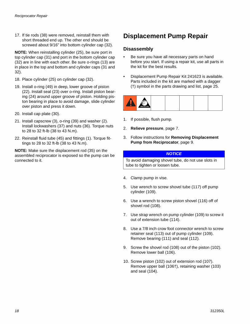
NOTE: When attaching the motor housing (43) onto the bottom cylinder cap (32), be sure that the port (43b) in the motor housing and the port (32b) in the bottom cylin-der cap are facing opposite directions as shown in FIG. 14.
FIG. 11
FIG. 12
60a
1a
60
1
30
3
39
2
36
37
FIG. 13
FIG. 14
16
32
32b 32
43b43
Service
312350L 13
3. Install seal (44) on retainer nut (11). Install retainer nut in pump adapter (8) (FIG. 14). Torque retainer nut to 54 to 56 ft-lbs (73-75 N.m).
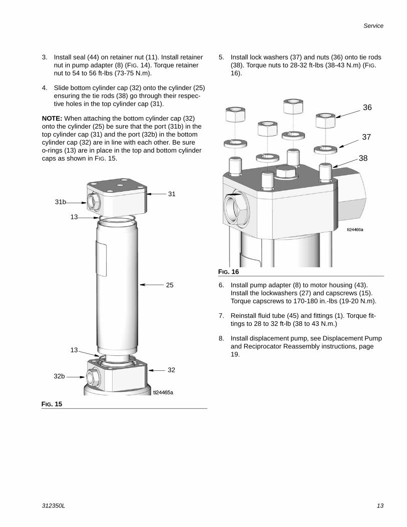
4. Slide bottom cylinder cap (32) onto the cylinder (25) ensuring the tie rods (38) go through their respec-tive holes in the top cylinder cap (31).
NOTE: When attaching the bottom cylinder cap (32) onto the cylinder (25) be sure that the port (31b) in the top cylinder cap (31) and the port (32b) in the bottom cylinder cap (32) are in line with each other. Be sure o-rings (13) are in place in the top and bottom cylinder caps as shown in FIG. 15.
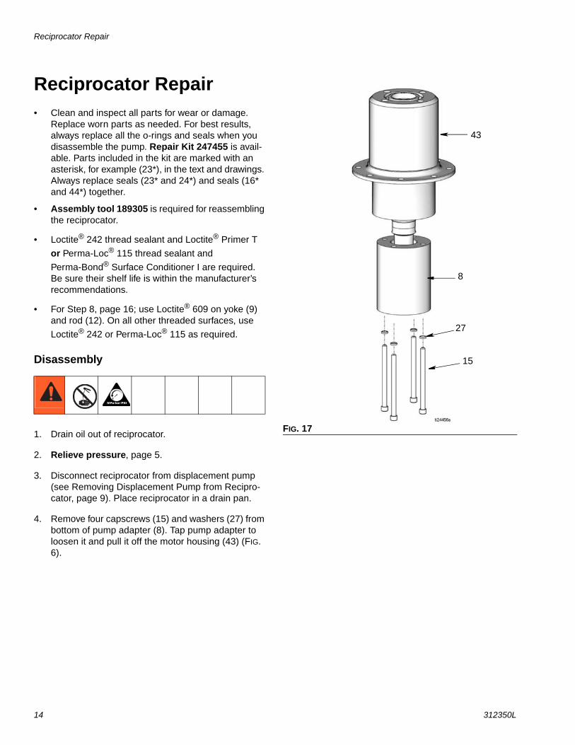
5. Install lock washers (37) and nuts (36) onto tie rods (38). Torque nuts to 28-32 ft-lbs (38-43 N.m) (FIG. 16).
6. Install pump adapter (8) to motor housing (43). Install the lockwashers (27) and capscrews (15). Torque capscrews to 170-180 in.-lbs (19-20 N.m).
7. Reinstall fluid tube (45) and fittings (1). Torque fit-tings to 28 to 32 ft-lb (38 to 43 N.m.)
8. Install displacement pump, see Displacement Pump and Reciprocator Reassembly instructions, page 19.
FIG. 15
3131b
13
25
3232b
13
FIG. 16
37
36
38
Reciprocator Repair
14 312350L
Reciprocator Repair• Clean and inspect all parts for wear or damage.
Replace worn parts as needed. For best results, always replace all the o-rings and seals when you disassemble the pump. Repair Kit 247455 is avail-able. Parts included in the kit are marked with an asterisk, for example (23*), in the text and drawings. Always replace seals (23* and 24*) and seals (16* and 44*) together.
• Assembly tool 189305 is required for reassembling the reciprocator.
• Loctite® 242 thread sealant and Loctite® Primer T
or Perma-Loc® 115 thread sealant and
Perma-Bond® Surface Conditioner I are required. Be sure their shelf life is within the manufacturer’s recommendations.
• For Step 8, page 16; use Loctite® 609 on yoke (9) and rod (12). On all other threaded surfaces, use
Loctite® 242 or Perma-Loc® 115 as required.
Disassembly
1. Drain oil out of reciprocator.
2. Relieve pressure, page 5.
3. Disconnect reciprocator from displacement pump (see Removing Displacement Pump from Recipro-cator, page 9). Place reciprocator in a drain pan.
4. Remove four capscrews (15) and washers (27) from bottom of pump adapter (8). Tap pump adapter to loosen it and pull it off the motor housing (43) (FIG. 6).
FIG. 17
15
27
8
43
Reciprocator Repair
312350L 15
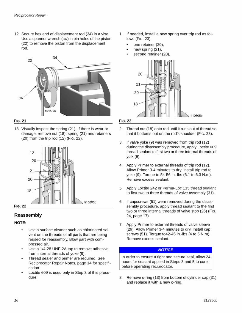
5. Place bottom cap (32) in vise. Remove four cap-screws (46) and lockwashers (52).
6. Pull adapter (43) off bottom cap (32). Inspect seals. If needed, replace seals. See Replacing Throat Seal Disassembly instructions on page 10.
7. Remove capscrew (3), nuts (36) and lockwashers (37) on top of reciprocator.
8. Remove cap plate (30) (FIG. 19).
9. Use a rubber or plastic head mallet to tap the bot-tom of the displacement rod (35) and loosen cylin-der (25).
10. Grasp top of cylinder cap (31) and pull the displace-ment rod (35) out of the cylinder (25). Lay assembly on its side.
NOTE: It is not necessary to remove tie rods (38) from the bottom cylinder cap (32).
11. Place a clean rag around yoke (9) to prevent losing detent balls (7) and spring (6) installed in the valve stop (26). Lightly push down the valve stop with your thumbs while gripping yoke to disengage yoke from valve stop and valve sleeve (29).
FIG. 18
FIG. 19
43
46
52
3
36
3730
FIG. 20
26
9
29
rag
Reciprocator Repair
16 312350L
12. Secure hex end of displacement rod (34) in a vise. Use a spanner wrench (sw) in pin holes of the piston (22) to remove the piston from the displacement rod.
13. Visually inspect the spring (21). If there is wear or damage, remove nut (18), spring (21) and retainers (20) from the trip rod (12) (FIG. 22).
Reassembly
NOTE:
• Use a surface cleaner such as chlorinated sol-vent on the threads of all parts that are being reused for reassembly. Blow part with com-pressed air.
• Use a 1/4-28 UNF-2A tap to remove adhesive from internal threads of yoke (9).
• Thread sealer and primer are required. See Reciprocator Repair Notes, page 14 for specifi-cation.
• Loctite 609 is used only in Step 3 of this proce-dure.
1. If needed, install a new spring over trip rod as fol-lows (FIG. 23):
• one retainer (20),• new spring (21),• second retainer (20).
2. Thread nut (18) onto rod until it runs out of thread so that it bottoms out on the rod’s shoulder (FIG. 23).
3. If valve yoke (9) was removed from trip rod (12) during the disassembly procedure, apply Loctite 609 thread sealant to first two or three internal threads of yolk (9).
4. Apply Primer to external threads of trip rod (12). Allow Primer 3-4 minutes to dry. Install trip rod to yoke (9). Torque to 54-56 in.-lbs (6.1 to 6.3 N.m). Remove excess sealant.
5. Apply Loctite 242 or Perma-Loc 115 thread sealant to first two to three threads of valve assembly (31).
6. If capscrews (51) were removed during the disas-sembly procedure, apply thread sealant to the first two or three internal threads of valve stop (26) (FIG. 24, page 17).
7. Apply Primer to external threads of valve sleeve (29). Allow Primer 3-4 minutes to dry. Install cap screws (51). Torque to42-45 in.-lbs (4 to 5 N.m). Remove excess sealant.
8. Remove o-ring (13) from bottom of cylinder cap (31) and replace it with a new o-ring.
FIG. 21
FIG. 22
3422
sw
18
20
21
20
12
FIG. 23
NOTICE
In order to ensure a tight and secure seal, allow 24 hours for sealant applied in Steps 3 and 5 to cure before operating reciprocator.
18
20
21
20
Reciprocator Repair
312350L 17
9. Use a spanner wrench to screw piston (22) onto displacement rod (34). Torque to 40 to 48 ft-lb (54 to 65 N.m).
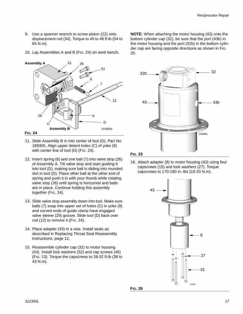
10. Lay Assemblies A and B (FIG. 24) on work bench.
11. Slide Assembly B in into center of tool (D), Part No. 189305. Align upper detent holes (C) of yoke (9) with center line of tool (D) (FIG. 24).
12. Insert spring (6) and one ball (7) into valve stop (26) of Assembly A. Tilt valve stop and start guiding it into tool (D), making sure ball is sliding into rounded slot in tool (D). Place other ball at the other end of spring and push it in with your thumb while rotating valve stop (26) until spring is horizontal and balls are in place. Continue holding this assembly together (FIG. 24).
13. Slide valve stop assembly down into tool. Make sure balls (7) snap into upper set of holes (C) in yoke (9) and curved ends of guide clamp have engaged valve sleeve (29) groove. Slide tool (D) back over rod (12) to remove it (FIG. 24).
14. Place adapter (43) in a vise. Install seals as described in Replacing Throat Seal Reassembly instructions, page 12.
15. Reassemble cylinder cap (32) to motor housing (43). Install lock washers (52) and cap screws (46) (FIG. 13). Torque the capscrews to 28-32 ft-lb (38 to 43 N.m).
NOTE: When attaching the motor housing (43) onto the bottom cylinder cap (32), be sure that the port (43b) in the motor housing and the port (32b) in the bottom cylin-der cap are facing opposite directions as shown in FIG. 25.
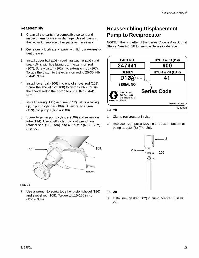
16. Attach adapter (8) to motor housing (43) using four capscrews (15) and lock washers (27). Torque capscrews to 170-180 in.-lbs (19-20 N.m).
FIG. 24
9
ti10606a
12
DC
76
Assembly A
Assembly B
31 2651
29
FIG. 25
FIG. 26
32b 32
43b43
8
43
27
15
Reciprocator Repair
18 312350L
17. If tie rods (38) were removed, reinstall them with short threaded end up. The other end should be screwed about 9/16” into bottom cylinder cap (32).
NOTE: When reinstalling cylinder (25), be sure port in top cylinder cap (31) and port in the bottom cylinder cap (32) are in line with each other. Be sure o-rings (13) are in place in the top and bottom and cylinder caps (31 and 32).
18. Place cylinder (25) on cylinder cap (32).
19. Install o-ring (49) in deep, lower groove of piston (22). Install seal (23) over o-ring. Install piston bear-ing (24) around upper groove of piston. Holding pis-ton bearing in place to avoid damage, slide cylinder over piston and press it down.
20. Install cap plate (30).
21. Install capscrew (3), o-ring (39) and washer (2). Install lockwashers (37) and nuts (36). Torque nuts to 28 to 32 ft-lb (38 to 43 N.m).
22. Reinstall fluid tube (45) and fittings (1). Torque fit-tings to 28 to 32 ft-lb (38 to 43 N.m).
NOTE: Make sure the displacement rod (35) on the assembled reciprocator is exposed so the pump can be connected to it.
Displacement Pump Repair
Disassembly
• Be sure you have all necessary parts on hand before you start. If using a repair kit, use all parts in the kit for the best results.
• Displacement Pump Repair Kit 241623 is available. Parts included in the kit are marked with a dagger (†) symbol in the parts drawing and list, page 25.
1. If possible, flush pump.
2. Relieve pressure, page 7.
3. Follow instructions for Removing Displacement Pump from Reciprocator, page 9.
4. Clamp pump in vise.
5. Use wrench to screw shovel tube (117) off pump cylinder (109).
6. Use a wrench to screw piston shovel (116) off of shovel rod (108).
7. Use strap wrench on pump cylinder (109) to screw it out of extension tube (114).
8. Use a 7/8 inch crow foot connector wrench to screw retainer seal (113) out of pump cylinder (109). Remove bearing (111) and seal (112).
9. Screw the shovel rod (108) out of the piston (102). Remove lower ball (106).
10. Screw piston (102) out of extension rod (107). Remove upper ball (106†), retaining washer (103) and seal (104).
NOTICETo avoid damaging shovel tube, do not use slots in tube to tighten or loosen tube.
Reciprocator Repair
312350L 19
Reassembly
1. Clean all the parts in a compatible solvent and inspect them for wear or damage. Use all parts in the repair kit, replace other parts as necessary.
2. Generously lubricate all parts with light, water-resis-tant grease.
3. Install upper ball (106), retaining washer (103) and seal (104), with lips facing up, in extension rod (107). Screw piston (102) into extension rod (107). Torque the piston to the extension rod to 25-30 ft-lb (34-41 N.m).
4. Install lower ball (106) into end of shovel rod (108). Screw the shovel rod (108) to piston (102). torque the shovel rod to the piston to 25-30 ft-lb (34-41 N.m).
5. Install bearing (111) and seal (112) with lips facing up, in pump cylinder (109). Screw retainer seal (113) into pump cylinder (109).
6. Screw together pump cylinder (109) and extension tube (114). Use a 7/8 inch crow foot wrench on retainer seal (113). torque to 45-55 ft-lb (61-75 N.m) (FIG. 27).
7. Use a wrench to screw together piston shovel (116) and shovel rod (108). Torque to 115-125 in.-lb (13-14 N.m).
Reassembling Displacement Pump to ReciprocatorNOTE: If the last letter of the Series Code is A or B, omit Step 2. See FIG. 28 for sample Series Code label.
1. Clamp reciprocator in vise.
2. Replace nylon pellet (207) in threads on bottom of pump adapter (8) (FIG. 29).
3. Install new gasket (202) in pump adapter (8) (FIG. 29).
FIG. 27
113 109
FIG. 28
FIG. 29
Series Code
207
8
202
Reciprocator Repair
20 312350L
4. Screw connecting rod (107) into displacement rod (35) until holes align. Install cotter pin (204) through holes.
5. Apply thread lubricant to spacer tube (114) and thread into pump adapter (8). Use a 7/8 inch crow foot wrench on retainer seal (113). torque to 45-55 ft-lb (61-75 N.m) (FIG. 27).
6. Use a strap wrench to screw together shovel tube (117) and pump cylinder (109).
7. Connect hydraulic supply and return hoses to fit-tings (5, 60).
FIG. 30
FIG. 31
114
8
107
204
35
107
113
117
To reduce risk of static sparking, be sure to reconnect ground wire before operating pump.
Reciprocator Repair
312350L 21
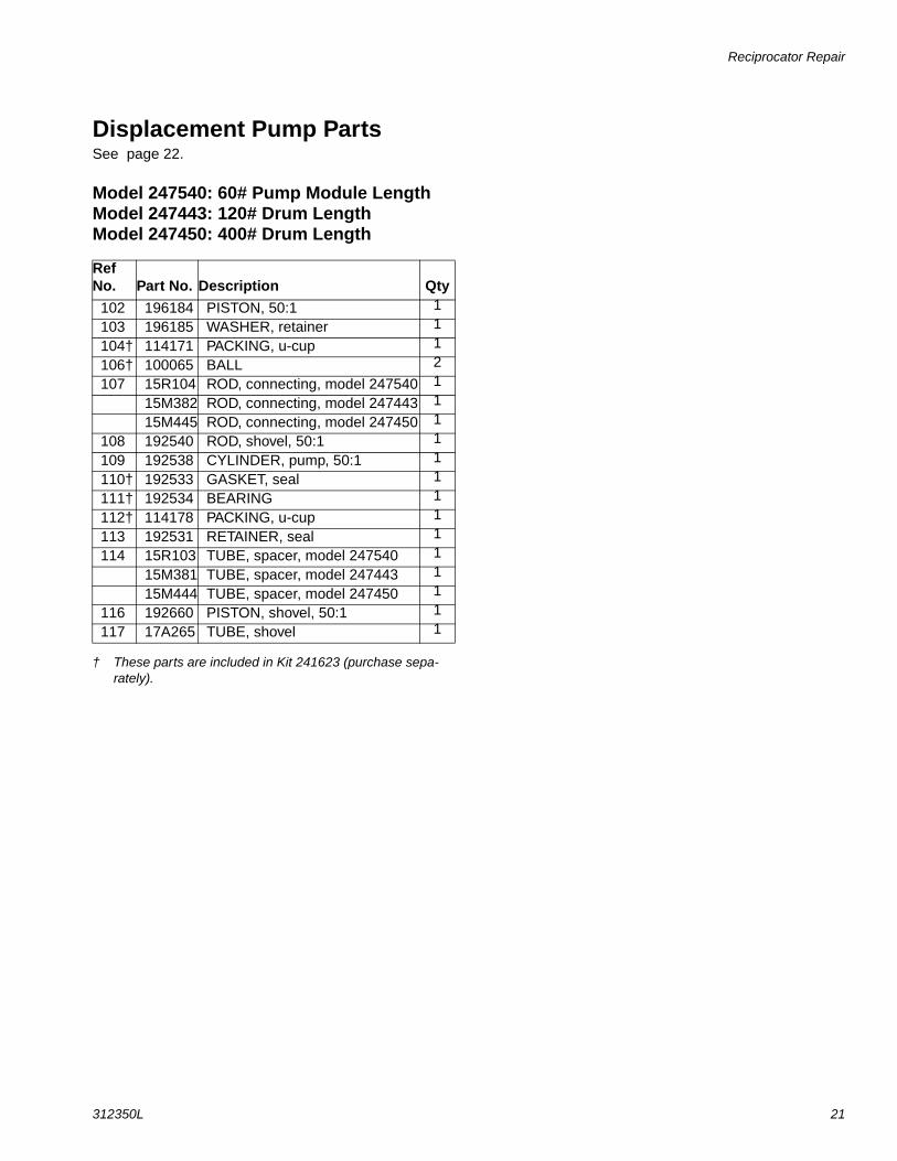
Displacement Pump PartsSee page 22.
Model 247540: 60# Pump Module LengthModel 247443: 120# Drum LengthModel 247450: 400# Drum Length
† These parts are included in Kit 241623 (purchase sepa-rately).
Ref No. Part No. Description Qty
102 196184 PISTON, 50:1 1
103 196185 WASHER, retainer 1
104† 114171 PACKING, u-cup 1
106† 100065 BALL 2
107 15R104 ROD, connecting, model 247540 1
15M382 ROD, connecting, model 247443 1
15M445 ROD, connecting, model 247450 1
108 192540 ROD, shovel, 50:1 1
109 192538 CYLINDER, pump, 50:1 1
110† 192533 GASKET, seal 1
111† 192534 BEARING 1
112† 114178 PACKING, u-cup 1
113 192531 RETAINER, seal 1
114 15R103 TUBE, spacer, model 247540 1
15M381 TUBE, spacer, model 247443 1
15M444 TUBE, spacer, model 247450 1
116 192660 PISTON, shovel, 50:1 1
117 17A265 TUBE, shovel 1
Reciprocator Repair
22 312350L
FIG. 32
117
116
108
113
111†112†
109
102
106†
104†103
110†106†
114
107
Assembled / Cutaway View
Using nut (113), torque the pump cylinder 109 to the extension tube (114) at 45 to 55 ft-lb (61 to 75 N.m).1
Torque the shovel rod (108) to the piston (102) at 25 to 30 ft-lb (34 to 41 N.m).3
Torque the piston (102) to the extension rod (107) at 25 to 30 ft-lb (34 to 41 N.m).4
1
4
7
3
7
Assemble with lips facing up.7
ti10608a
ti10609a
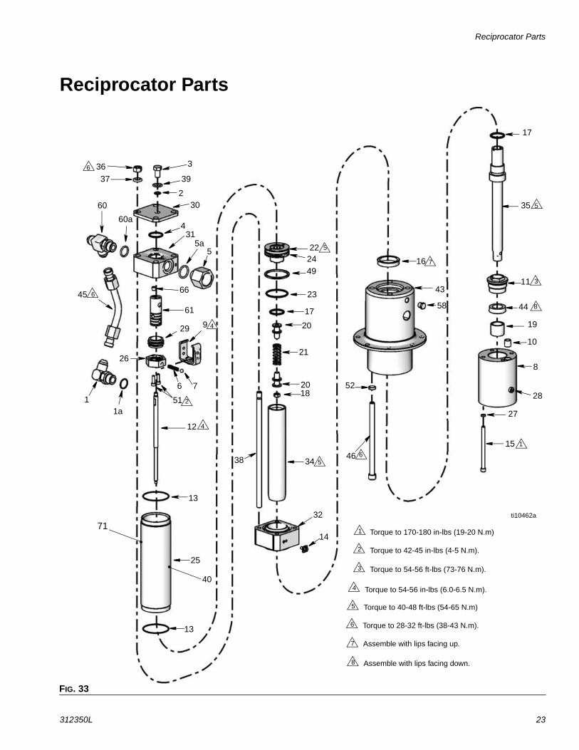
Reciprocator Parts
312350L 23
Reciprocator Parts
FIG. 33
36
37
3
39
23060
4
5
61
66
60a
5a
45
29 9
76
51
12
1
13
25
40
13
14
32
3438
1820
21
20
23
17
49
2224
58
26
1a
43
16
35
44
8
28
27
1546
52
11
19
31
4
5
3
6
5
5
1
6
6
2
Torque to 170-180 in-lbs (19-20 N.m)1
Torque to 42-45 in-lbs (4-5 N.m).2
Torque to 54-56 ft-lbs (73-76 N.m).3
Torque to 54-56 in-lbs (6.0-6.5 N.m).4
Torque to 40-48 ft-lbs (54-65 N.m)5
Torque to 28-32 ft-lbs (38-43 N.m).6
Assemble with lips facing up.7
Assemble with lips facing down.8
7
8
4
17
10
ti10462a
71
Reciprocator Parts
24 312350L
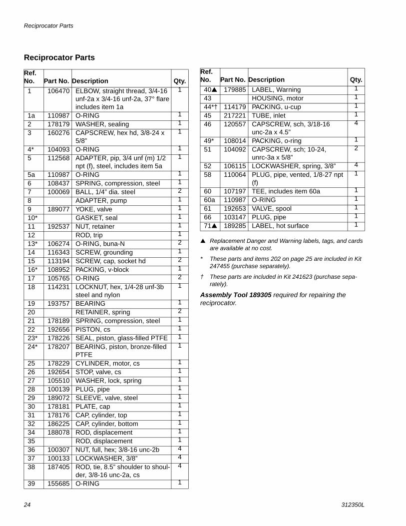
Reciprocator Parts
Replacement Danger and Warning labels, tags, and cards are available at no cost.
* These parts and items 202 on page 25 are included in Kit 247455 (purchase separately).
† These parts are included in Kit 241623 (purchase sepa-rately).
Assembly Tool 189305 required for repairing the reciprocator.
Ref. No. Part No. Description Qty.
1 106470 ELBOW, straight thread, 3/4-16 unf-2a x 3/4-16 unf-2a, 37° flare includes item 1a
1
1a 110987 O-RING 1
2 178179 WASHER, sealing 1
3 160276 CAPSCREW, hex hd, 3/8-24 x 5/8”
1
4* 104093 O-RING 1
5 112568 ADAPTER, pip, 3/4 unf (m) 1/2 npt (f), steel, includes item 5a
1
5a 110987 O-RING 1
6 108437 SPRING, compression, steel 1
7 100069 BALL, 1/4” dia. steel 2
8 ADAPTER, pump 1
9 189077 YOKE, valve 1
10* GASKET, seal 1
11 192537 NUT, retainer 1
12 ROD, trip 1
13* 106274 O-RING, buna-N 2
14 116343 SCREW, grounding 1
15 113194 SCREW, cap, socket hd 2
16* 108952 PACKING, v-block 1
17 105765 O-RING 2
18 114231 LOCKNUT, hex, 1/4-28 unf-3b steel and nylon
1
19 193757 BEARING 1
20 RETAINER, spring 2
21 178189 SPRING, compression, steel 1
22 192656 PISTON, cs 1
23* 178226 SEAL, piston, glass-filled PTFE 1
24* 178207 BEARING, piston, bronze-filled PTFE
1
25 178229 CYLINDER, motor, cs 1
26 192654 STOP, valve, cs 1
27 105510 WASHER, lock, spring 1
28 100139 PLUG, pipe 1
29 189072 SLEEVE, valve, steel 1
30 178181 PLATE, cap 1
31 178176 CAP, cylinder, top 1
32 186225 CAP, cylinder, bottom 1
34 188078 ROD, displacement 1
35 ROD, displacement 1
36 100307 NUT, full, hex; 3/8-16 unc-2b 4
37 100133 LOCKWASHER, 3/8” 4
38 187405 ROD, tie, 8.5” shoulder to shoul-der, 3/8-16 unc-2a, cs
4
39 155685 O-RING 1
40 179885 LABEL, Warning 1
43 HOUSING, motor 1
44*† 114179 PACKING, u-cup 1
45 217221 TUBE, inlet 1
46 120557 CAPSCREW, sch, 3/18-16 unc-2a x 4.5”
4
49* 108014 PACKING, o-ring 1
51 104092 CAPSCREW, sch; 10-24, unrc-3a x 5/8”
2
52 106115 LOCKWASHER, spring, 3/8” 4
58 110064 PLUG, pipe, vented, 1/8-27 npt (f)
1
60 107197 TEE, includes item 60a 1
60a 110987 O-RING 1
61 192653 VALVE, spool 1
66 103147 PLUG, pipe 1
71 189285 LABEL, hot surface 1
Ref. No. Part No. Description Qty.
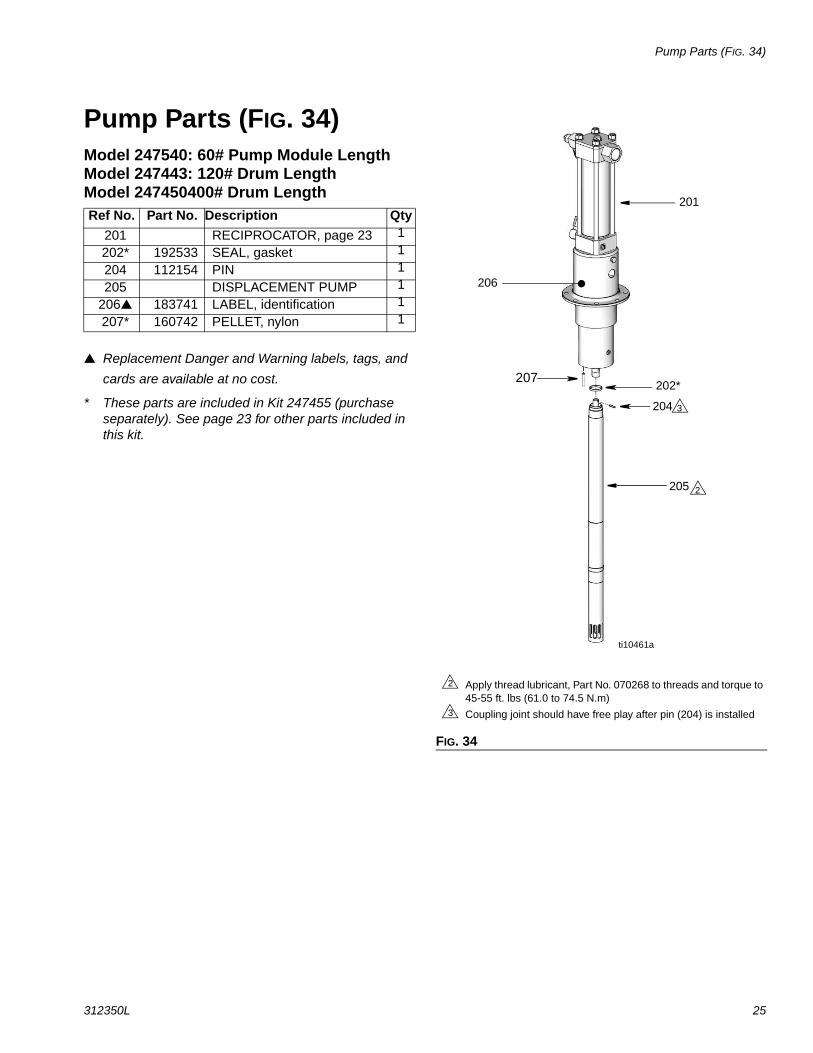
Pump Parts (FIG. 34)
312350L 25
Pump Parts (FIG. 34)Model 247540: 60# Pump Module LengthModel 247443: 120# Drum LengthModel 247450400# Drum Length
Replacement Danger and Warning labels, tags, and
cards are available at no cost.
* These parts are included in Kit 247455 (purchase separately). See page 23 for other parts included in this kit.
Ref No. Part No. Description Qty
201 RECIPROCATOR, page 23 1
202* 192533 SEAL, gasket 1
204 112154 PIN 1
205 DISPLACEMENT PUMP 1
206 183741 LABEL, identification 1
207* 160742 PELLET, nylon 1
FIG. 34
Coupling joint should have free play after pin (204) is installed3
201
206
202*
204
205
ti10461a
2
3
Apply thread lubricant, Part No. 070268 to threads and torque to 45-55 ft. lbs (61.0 to 74.5 N.m)
2
207
Technical Data
26 312350L
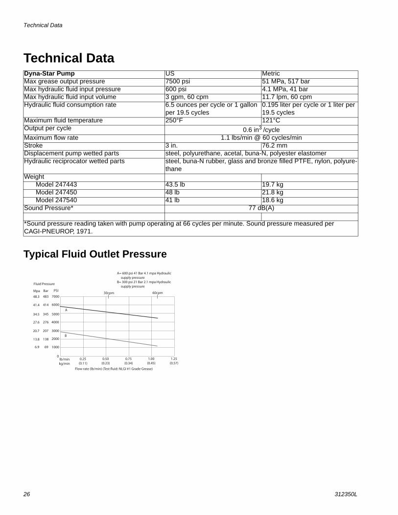
Technical Data
Typical Fluid Outlet Pressure
Dyna-Star Pump US MetricMax grease output pressure 7500 psi 51 MPa, 517 barMax hydraulic fluid input pressure 600 psi 4.1 MPa, 41 barMax hydraulic fluid input volume 3 gpm, 60 cpm 11.7 lpm, 60 cpmHydraulic fluid consumption rate 6.5 ounces per cycle or 1 gallon
per 19.5 cycles0.195 liter per cycle or 1 liter per 19.5 cycles
Maximum fluid temperature 250°F 121°COutput per cycle 0.6 in3 /cycleMaximum flow rate 1.1 lbs/min @ 60 cycles/minStroke 3 in. 76.2 mmDisplacement pump wetted parts steel, polyurethane, acetal, buna-N, polyester elastomerHydraulic reciprocator wetted parts steel, buna-N rubber, glass and bronze filled PTFE, nylon, polyure-
thaneWeight
Model 247443 43.5 lb 19.7 kgModel 247450 48 lb 21.8 kgModel 247540 41 lb 18.6 kg
Sound Pressure* 77 dB(A)
*Sound pressure reading taken with pump operating at 66 cycles per minute. Sound pressure measured per CAGI-PNEUROP, 1971.
Technical Data
312350L 27
Dimensions and Mounting Hole Layout
1/8 npt throat sealweep port
3/4” - 16 JIC37° flare (m)
1/2 npt(f)fluid outlet
3/4 npt Hydraulic Outlet
14.75 in.(375 mm)
41.5 in.(1054 mm)Model 247443
48.5 in.(1232 mm)Model 247450
3.5 (88.9 mm)minimum diameter clearance hole
3.536 in.(90.424 mm)
3.536 in.(90.424 mm)
clearance for, or tap 5/16-18typical 4 places
33.9 in.(861 mm)Model 247540
Graco Standard Warranty
28 312350L
Graco Standard WarrantyGraco warrants all equipment referenced in this document which is manufactured by Graco and bearing its name to be free from defects in material and workmanship on the date of sale to the original purchaser for use. With the exception of any special, extended, or limited warranty published by Graco, Graco will, for a period of twelve months from the date of sale, repair or replace any part of the equipment determined by Graco to be defective. This warranty applies only when the equipment is installed, operated and maintained in accordance with Graco’s written recommendations.
This warranty does not cover, and Graco shall not be liable for general wear and tear, or any malfunction, damage or wear caused by faulty installation, misapplication, abrasion, corrosion, inadequate or improper maintenance, negligence, accident, tampering, or substitution of non-Graco component parts. Nor shall Graco be liable for malfunction, damage or wear caused by the incompatibility of Graco equipment with structures, accessories, equipment or materials not supplied by Graco, or the improper design, manufacture, installation, operation or maintenance of structures, accessories, equipment or materials not supplied by Graco.
This warranty is conditioned upon the prepaid return of the equipment claimed to be defective to an authorized Graco distributor for verification of the claimed defect. If the claimed defect is verified, Graco will repair or replace free of charge any defective parts. The equipment will be returned to the original purchaser transportation prepaid. If inspection of the equipment does not disclose any defect in material or workmanship, repairs will be made at a reasonable charge, which charges may include the costs of parts, labor, and transportation.
THIS WARRANTY IS EXCLUSIVE, AND IS IN LIEU OF ANY OTHER WARRANTIES, EXPRESS OR IMPLIED, INCLUDING BUT NOT LIMITED TO WARRANTY OF MERCHANTABILITY OR WARRANTY OF FITNESS FOR A PARTICULAR PURPOSE.
Graco’s sole obligation and buyer’s sole remedy for any breach of warranty shall be as set forth above. The buyer agrees that no other remedy (including, but not limited to, incidental or consequential damages for lost profits, lost sales, injury to person or property, or any other incidental or consequential loss) shall be available. Any action for breach of warranty must be brought within two (2) years of the date of sale.
GRACO MAKES NO WARRANTY, AND DISCLAIMS ALL IMPLIED WARRANTIES OF MERCHANTABILITY AND FITNESS FOR A PARTICULAR PURPOSE, IN CONNECTION WITH ACCESSORIES, EQUIPMENT, MATERIALS OR COMPONENTS SOLD BUT NOT MANUFACTURED BY GRACO. These items sold, but not manufactured by Graco (such as electric motors, switches, hose, etc.), are subject to the warranty, if any, of their manufacturer. Graco will provide purchaser with reasonable assistance in making any claim for breach of these warranties.
In no event will Graco be liable for indirect, incidental, special or consequential damages resulting from Graco supplying equipment hereunder, or the furnishing, performance, or use of any products or other goods sold hereto, whether due to a breach of contract, breach of warranty, the negligence of Graco, or otherwise.
FOR GRACO CANADA CUSTOMERSThe Parties acknowledge that they have required that the present document, as well as all documents, notices and legal proceedings entered into, given or instituted pursuant hereto or relating directly or indirectly hereto, be drawn up in English. Les parties reconnaissent avoir convenu que la rédaction du présente document sera en Anglais, ainsi que tous documents, avis et procédures judiciaires exécutés, donnés ou intentés, à la suite de ou en rapport, directement ou indirectement, avec les procédures concernées.
Graco Information For the latest information about Graco products, visit www.graco.com.
For patent information, see www.graco.com/patents.
TO PLACE AN ORDER, contact your Graco distributor or call to identify the nearest distributor.Phone: 612-623-6928 or Toll Free: 1-800-533-9655, Fax: 612-378-3590
All written and visual data contained in this document reflects the latest product information available at the time of publication. Graco reserves the right to make changes at any time without notice.
Original instructions. This manual contains English. MM 312350
Graco Headquarters: MinneapolisInternational Offices: Belgium, China, Japan, Korea
GRACO INC. P.O. BOX 1441 MINNEAPOLIS, MN 55440-1441
Copyright 2007, Graco Inc. is registered to I.S. EN ISO 9001www.graco.com
revised to L, October 2015