Embed Size (px)
Citation preview
Hydraulic Pumps
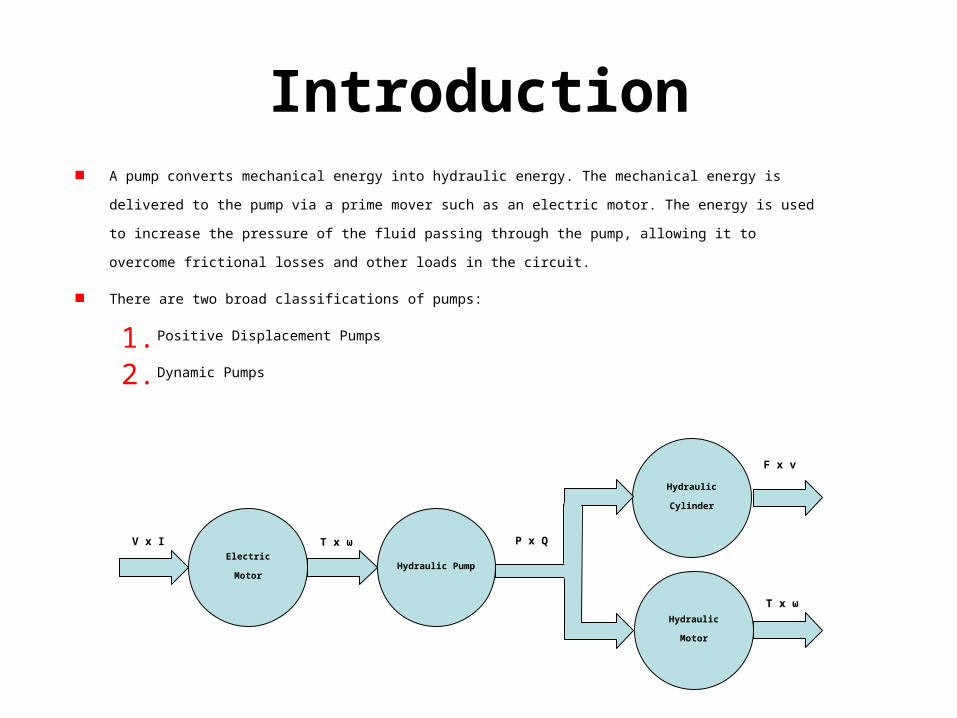
Introduction A pump converts mechanical energy into hydraulic energy. The mechanical energy is delivered to the pump via a prime mover
such as an electric motor. The energy is used to increase the pressure of the fluid passing through the pump, allowing it to
overcome frictional losses and other loads in the circuit.
There are two broad classifications of pumps:
1. Positive Displacement Pumps
2. Dynamic Pumps
Hydraulic Cylinder
Electric Motor
T x ωV x I
Hydraulic Pump
P x Q
Hydraulic Motor
F x v
T x ω
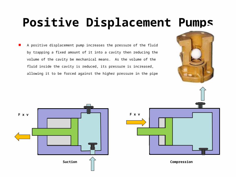
Positive Displacement Pumps
A positive displacement pump increases the pressure of the fluid by trapping a fixed amount of it
into a cavity then reducing the volume of the cavity be mechanical means. As the volume of the
fluid inside the cavity is reduced, its pressure is increased, allowing it to be forced against the
higher pressure in the pipe
F x vF x v
Suction Compression
4Day 1 - Session A
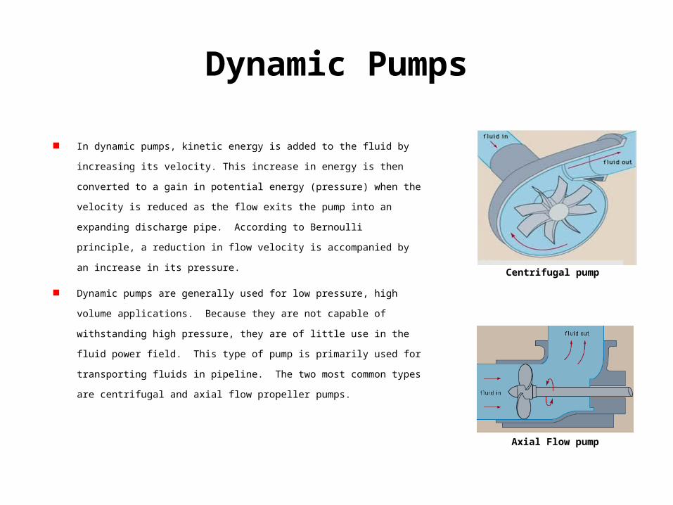
Dynamic Pumps
In dynamic pumps, kinetic energy is added to the fluid by increasing its velocity. This
increase in energy is then converted to a gain in potential energy (pressure) when the
velocity is reduced as the flow exits the pump into an expanding discharge pipe.
According to Bernoulli principle, a reduction in flow velocity is accompanied by an
increase in its pressure.
Dynamic pumps are generally used for low pressure, high volume applications. Because
they are not capable of withstanding high pressure, they are of little use in the fluid
power field. This type of pump is primarily used for transporting fluids in pipeline. The
two most common types are centrifugal and axial flow propeller pumps.
Centrifugal pump
Axial Flow pump
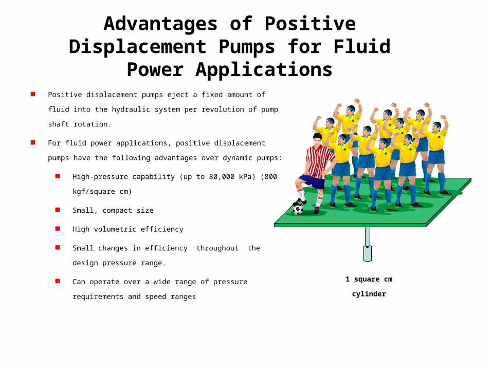
Advantages of Positive Displacement Pumps for Fluid Power Applications
Positive displacement pumps eject a fixed amount of fluid into the hydraulic
system per revolution of pump shaft rotation.
For fluid power applications, positive displacement pumps have the following
advantages over dynamic pumps:
High-pressure capability (up to 80,000 kPa) (800 kgf/square cm)
Small, compact size
High volumetric efficiency
Small changes in efficiency throughout the design pressure range.
Can operate over a wide range of pressure requirements and speed
ranges
1 square cm
cylinder
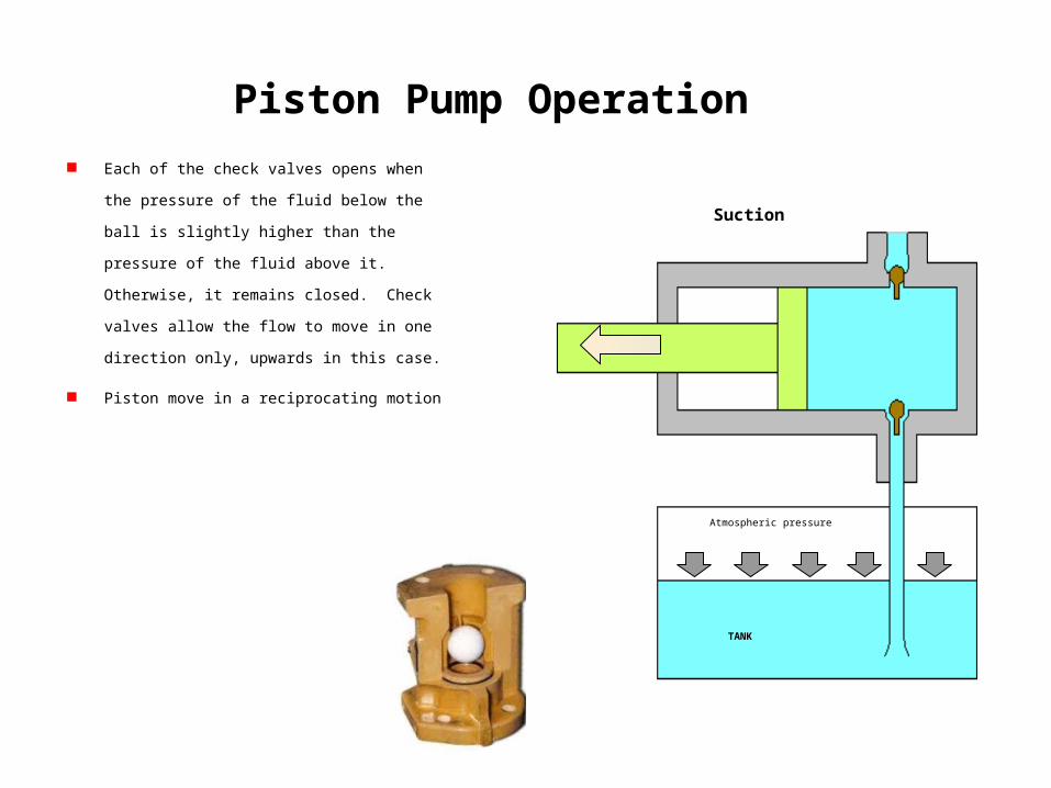
Piston Pump Operation
Each of the check valves opens when the pressure of
the fluid below the ball is slightly higher than the
pressure of the fluid above it. Otherwise, it remains
closed. Check valves allow the flow to move in one
direction only, upwards in this case.
Piston move in a reciprocating motion
Suction
Atmospheric pressure
TANK
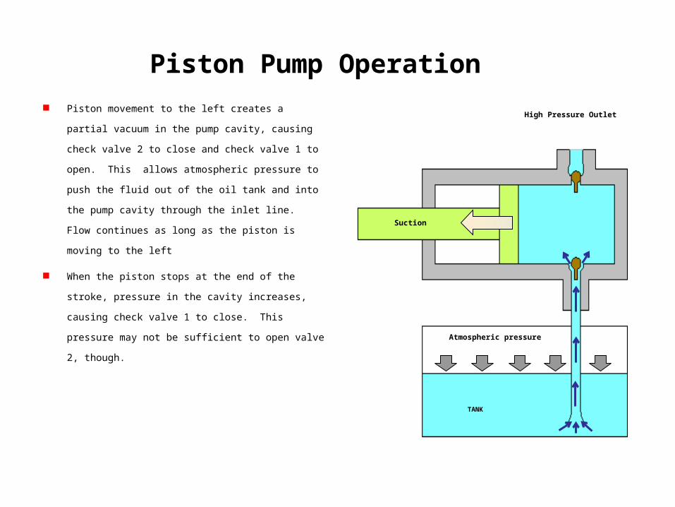
Piston Pump Operation
Piston movement to the left creates a partial vacuum in the pump
cavity, causing check valve 2 to close and check valve 1 to open.
This allows atmospheric pressure to push the fluid out of the oil
tank and into the pump cavity through the inlet line. Flow
continues as long as the piston is moving to the left
When the piston stops at the end of the stroke, pressure in the
cavity increases, causing check valve 1 to close. This pressure may
not be sufficient to open valve 2, though.
Atmospheric pressure
TANK
High Pressure Outlet
Suction
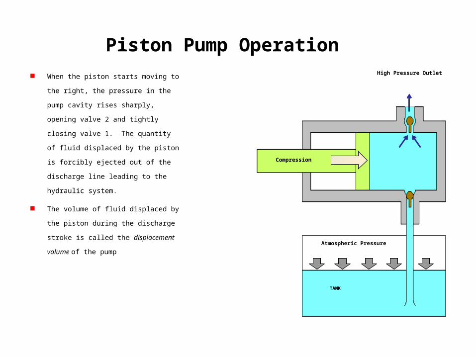
Piston Pump Operation
When the piston starts moving to the right, the
pressure in the pump cavity rises sharply,
opening valve 2 and tightly closing valve 1. The
quantity of fluid displaced by the piston is
forcibly ejected out of the discharge line leading
to the hydraulic system.
The volume of fluid displaced by the piston
during the discharge stroke is called the
displacement volume of the pump
TANK
High Pressure Outlet
Compression
Atmospheric Pressure
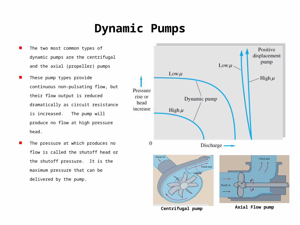
Dynamic Pumps
The two most common types of dynamic pumps
are the centrifugal and the axial (propeller) pumps
These pump types provide continuous non-
pulsating flow, but their flow output is reduced
dramatically as circuit resistance is increased. The
pump will produce no flow at high pressure head.
The pressure at which produces no flow is called
the shutoff head or the shutoff pressure. It is the
maximum pressure that can be delivered by the
pump.
Centrifugal pump Axial Flow pump
Dynamic Pumps
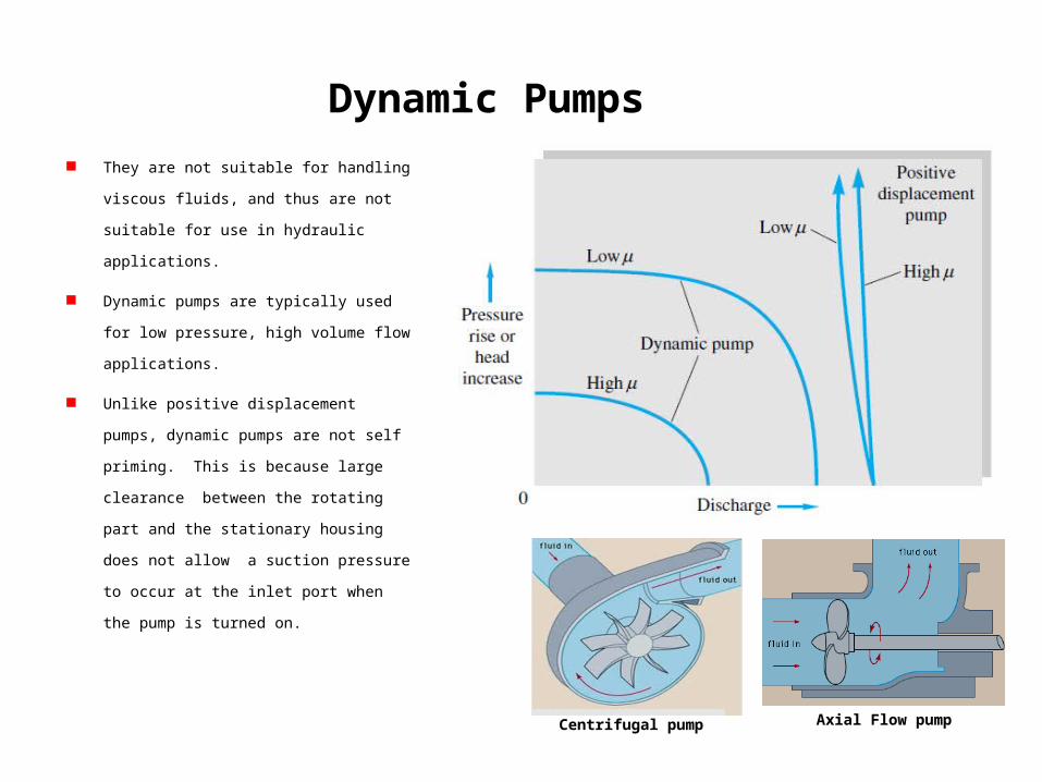
They are not suitable for handling viscous fluids,
and thus are not suitable for use in hydraulic
applications.
Dynamic pumps are typically used for low
pressure, high volume flow applications.
Unlike positive displacement pumps, dynamic
pumps are not self priming. This is because large
clearance between the rotating part and the
stationary housing does not allow a suction
pressure to occur at the inlet port when the pump
is turned on.
Centrifugal pump Axial Flow pump
Positive Displacement Pumps
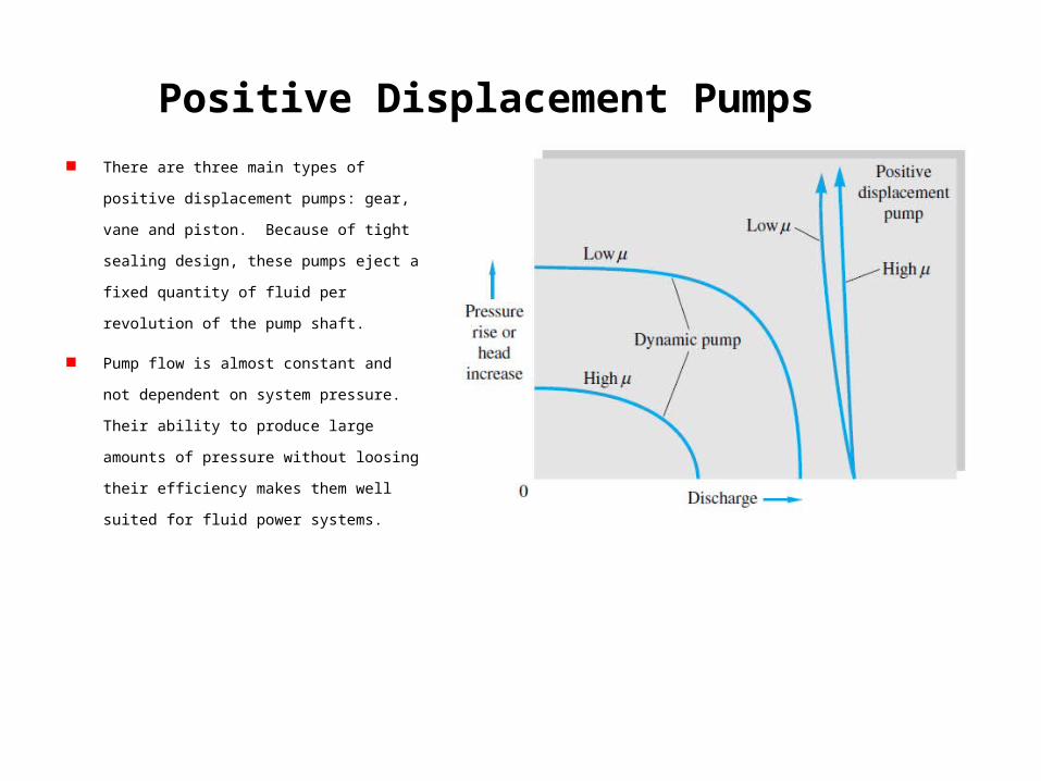
There are three main types of positive displacement
pumps: gear, vane and piston. Because of tight
sealing design, these pumps eject a fixed quantity of
fluid per revolution of the pump shaft.
Pump flow is almost constant and not dependent on
system pressure. Their ability to produce large
amounts of pressure without loosing their efficiency
makes them well suited for fluid power systems.
Positive Displacement Pumps
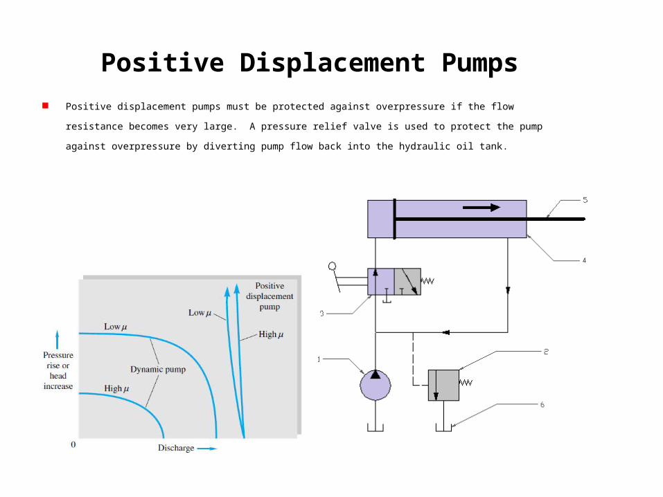
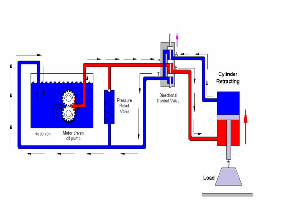
Positive displacement pumps must be protected against overpressure if the flow resistance becomes very large. A pressure
relief valve is used to protect the pump against overpressure by diverting pump flow back into the hydraulic oil tank.
Positive Displacement Pumps
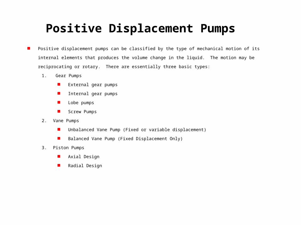
Positive displacement pumps can be classified by the type of mechanical motion of its internal elements that produces the
volume change in the liquid. The motion may be reciprocating or rotary. There are essentially three basic types:
1. Gear Pumps
External gear pumps
Internal gear pumps
Lobe pumps
Screw Pumps
2. Vane Pumps
Unbalanced Vane Pump (Fixed or variable displacement)
Balanced Vane Pump (Fixed Displacement Only)
3. Piston Pumps
Axial Design
Radial Design
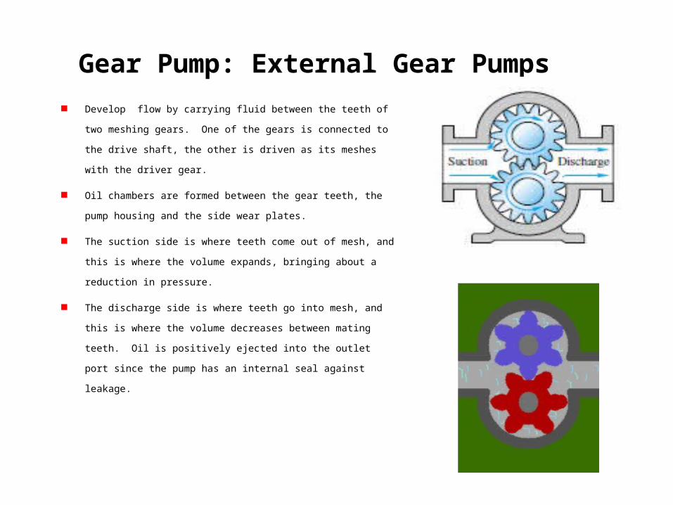
Gear Pump: External Gear Pumps
Develop flow by carrying fluid between the teeth of two meshing gears. One
of the gears is connected to the drive shaft, the other is driven as its meshes
with the driver gear.
Oil chambers are formed between the gear teeth, the pump housing and the
side wear plates.
The suction side is where teeth come out of mesh, and this is where the
volume expands, bringing about a reduction in pressure.
The discharge side is where teeth go into mesh, and this is where the volume
decreases between mating teeth. Oil is positively ejected into the outlet port
since the pump has an internal seal against leakage.
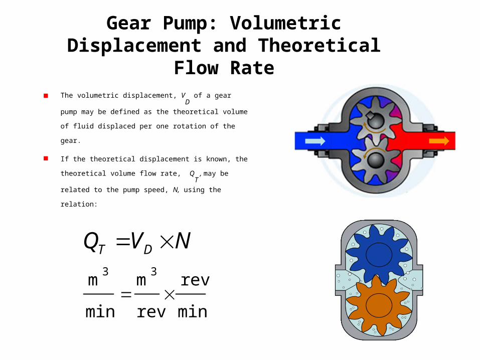
Gear Pump: Volumetric Displacement and Theoretical Flow Rate
The volumetric displacement, VD
of a gear pump may be defined
as the theoretical volume of fluid displaced per one rotation of the
gear.
If the theoretical displacement is known, the theoretical volume
flow rate, QT
, may be related to the pump speed, N, using the
relation:
min
rev
rev
m
min
m33
NVQ DT
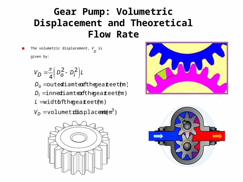
Gear Pump: Volumetric Displacement and Theoretical Flow Rate
The volumetric displacement, VD
is given by:
)
224
3(m ntdisplaceme volumetric
(m) teeth gear theof width
(m) teeth gear theof diamter inner
(m) teeth gear theof diamter outer
D
i
o
V
L
D
D
LiDoDDV
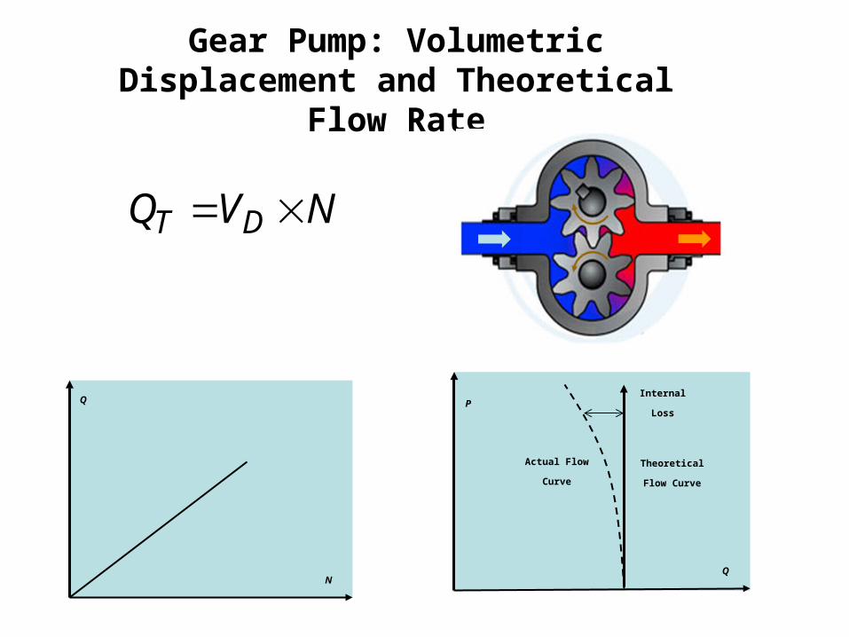
Gear Pump: Volumetric Displacement and Theoretical Flow Rate
NVQ DT
Q
N
P
Q
Theoretical Flow CurveActual Flow Curve
Internal Loss
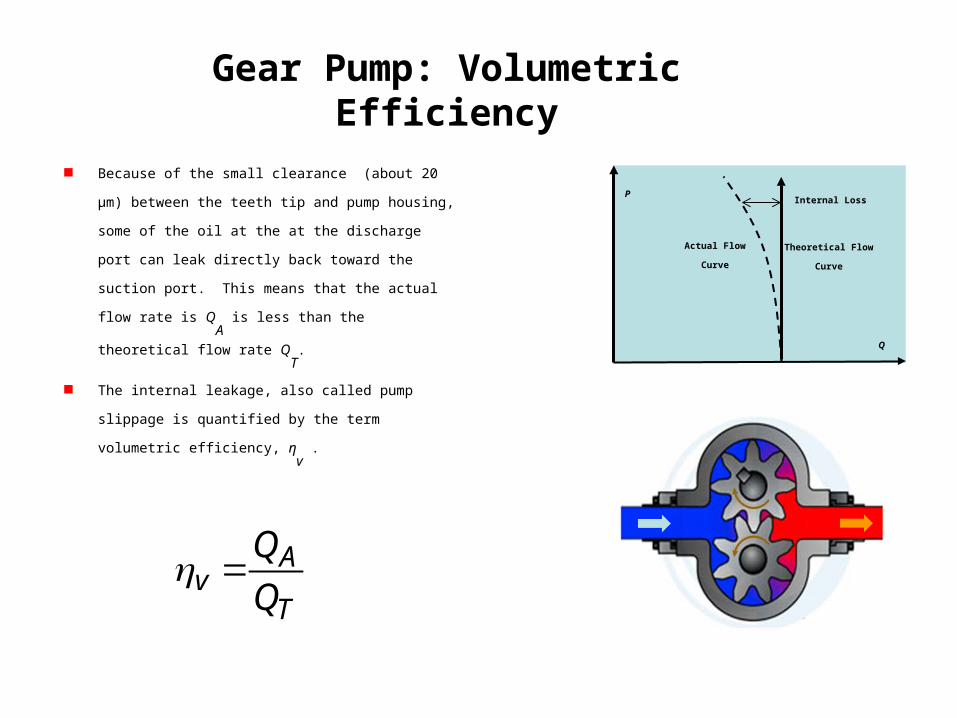
Gear Pump: Volumetric Efficiency
Because of the small clearance (about 20 µm) between the
teeth tip and pump housing, some of the oil at the at the
discharge port can leak directly back toward the suction port.
This means that the actual flow rate is QA
is less than the
theoretical flow rate QT
.
The internal leakage, also called pump slippage is quantified by
the term volumetric efficiency, ηv .
T
Av Q
Q
P
Q
Theoretical Flow CurveActual Flow Curve
Internal Loss
Gear Pump: Volumetric Efficiency
P
Q
Theoretical Flow
CurveActual Flow Curve
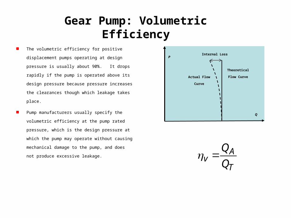
Internal Loss The volumetric efficiency for positive displacement pumps
operating at design pressure is usually about 90%. It drops
rapidly if the pump is operated above its design pressure
because pressure increases the clearances though which
leakage takes place.
Pump manufacturers usually specify the volumetric efficiency
at the pump rated pressure, which is the design pressure at
which the pump may operate without causing mechanical
damage to the pump, and does not produce excessive
leakage.
T
Av Q
Q
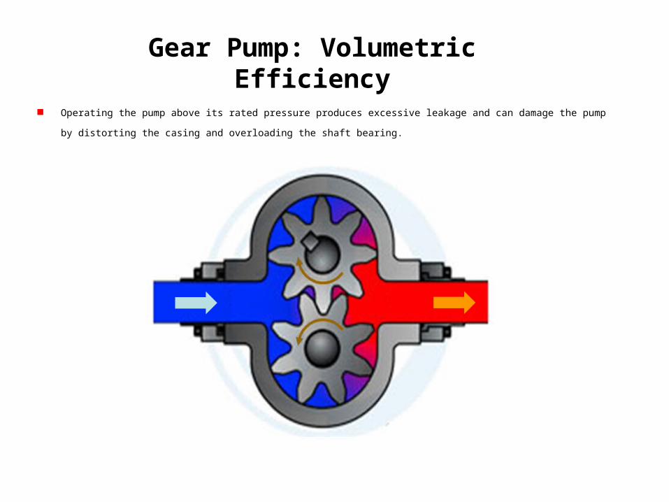
Gear Pump: Volumetric Efficiency
Operating the pump above its rated pressure produces excessive leakage and can damage the pump by distorting the casing and overloading
the shaft bearing.
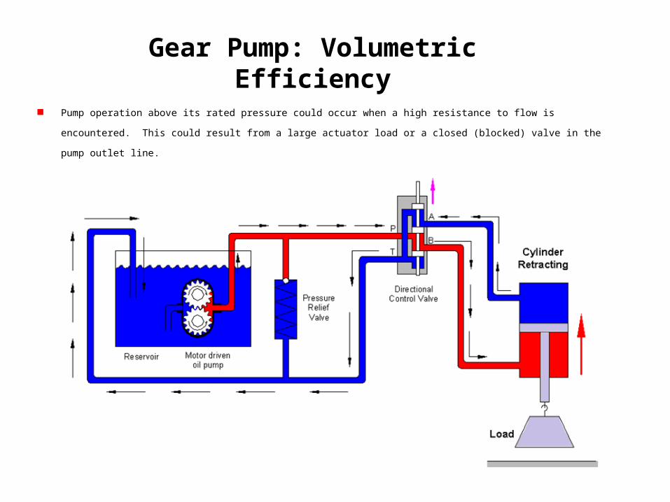
Gear Pump: Volumetric Efficiency
Pump operation above its rated pressure could occur when a high resistance to flow is encountered. This could result from a large actuator
load or a closed (blocked) valve in the pump outlet line.
Gear Pump: Volumetric Efficiency
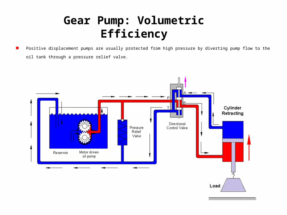
Positive displacement pumps are usually protected from high pressure by diverting pump flow to the oil tank through a pressure relief valve.
Example Gear Pump: Mizuhata Miniature Gear Pump
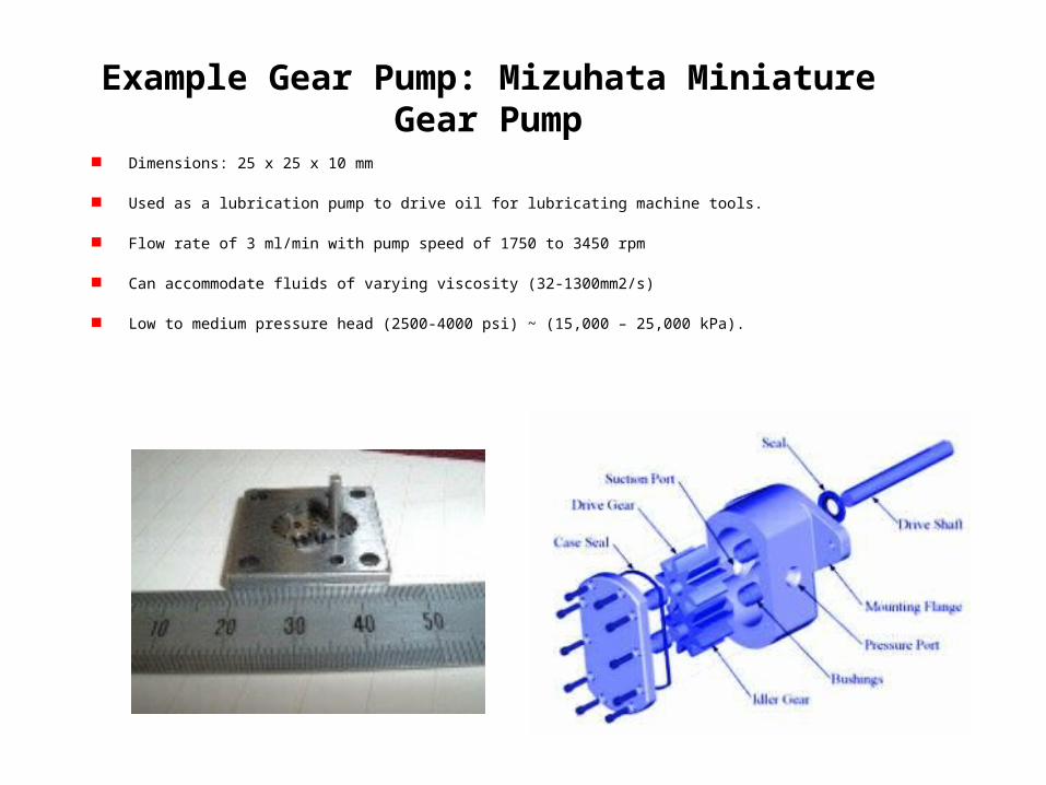
Dimensions: 25 x 25 x 10 mm
Used as a lubrication pump to drive oil for lubricating machine tools.
Flow rate of 3 ml/min with pump speed of 1750 to 3450 rpm
Can accommodate fluids of varying viscosity (32-1300mm2/s)
Low to medium pressure head (2500-4000 psi) ~ (15,000 – 25,000 kPa).
Gear Pump: Helical and Herringbone Gear
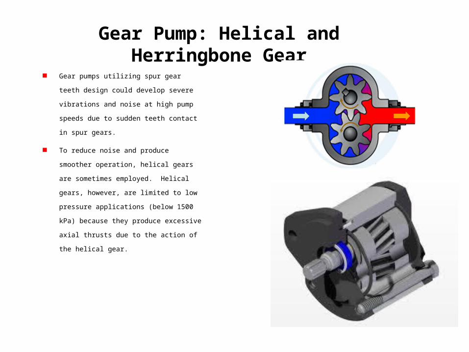
Gear pumps utilizing spur gear teeth design could
develop severe vibrations and noise at high pump
speeds due to sudden teeth contact in spur gears.
To reduce noise and produce smoother operation,
helical gears are sometimes employed. Helical
gears, however, are limited to low pressure
applications (below 1500 kPa) because they
produce excessive axial thrusts due to the action of
the helical gear.
Gear Pump: Helical and Herringbone Gear
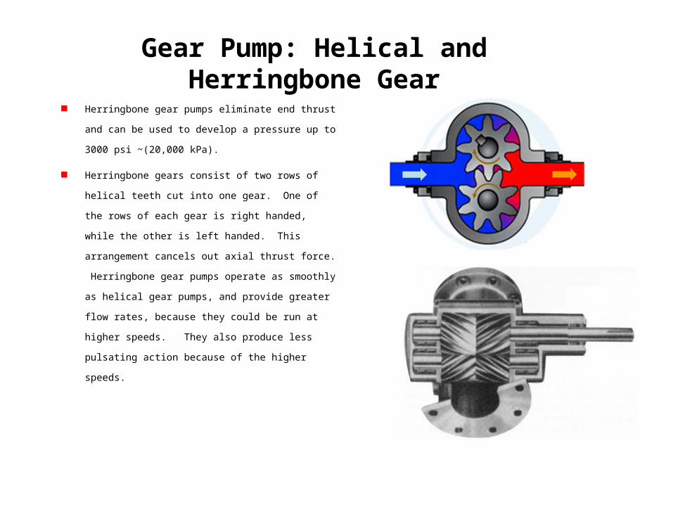
Herringbone gear pumps eliminate end thrust and can be used
to develop a pressure up to 3000 psi ~(20,000 kPa).
Herringbone gears consist of two rows of helical teeth cut into
one gear. One of the rows of each gear is right handed, while
the other is left handed. This arrangement cancels out axial
thrust force. Herringbone gear pumps operate as smoothly as
helical gear pumps, and provide greater flow rates, because
they could be run at higher speeds. They also produce less
pulsating action because of the higher speeds.
Internal Gear Pump
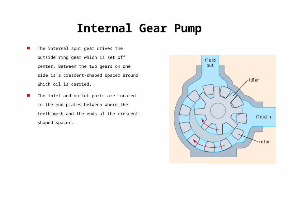
The internal spur gear drives the outside ring gear which is
set off center. Between the two gears on one side is a
crescent-shaped spacer around which oil is carried.
The inlet and outlet ports are located in the end plates
between where the teeth mesh and the ends of the
crescent-shaped spacer.
Internal Gear Pump
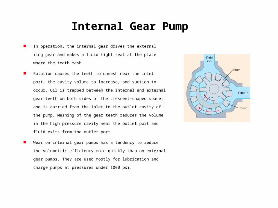
In operation, the internal gear drives the external ring gear and makes a fluid
tight seal at the place where the teeth mesh.
Rotation causes the teeth to unmesh near the inlet port, the cavity volume to
increase, and suction to occur. Oil is trapped between the internal and external
gear teeth on both sides of the crescent-shaped spacer and is carried from the
inlet to the outlet cavity of the pump. Meshing of the gear teeth reduces the
volume in the high pressure cavity near the outlet port and fluid exits from the
outlet port.
Wear on internal gear pumps has a tendency to reduce the volumetric efficiency
more quickly than on external gear pumps. They are used mostly for lubrication
and charge pumps at pressures under 1000 psi.
Internal Gear Pump
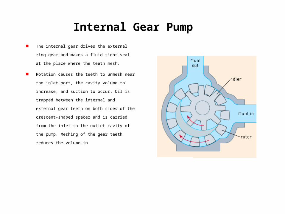
The internal gear drives the external ring gear and makes a
fluid tight seal at the place where the teeth mesh.
Rotation causes the teeth to unmesh near the inlet port,
the cavity volume to increase, and suction to occur. Oil is
trapped between the internal and external gear teeth on
both sides of the crescent-shaped spacer and is carried
from the inlet to the outlet cavity of the pump. Meshing of
the gear teeth reduces the volume in
Gerotor Pump
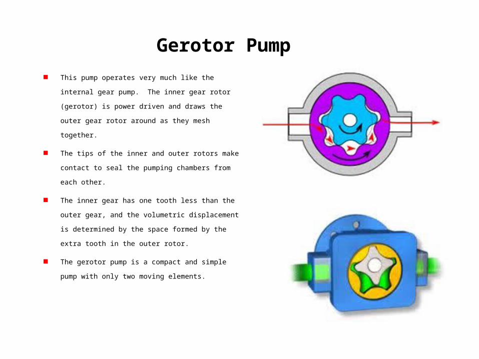
This pump operates very much like the internal gear pump. The
inner gear rotor (gerotor) is power driven and draws the outer
gear rotor around as they mesh together.
The tips of the inner and outer rotors make contact to seal the
pumping chambers from each other.
The inner gear has one tooth less than the outer gear, and the
volumetric displacement is determined by the space formed by
the extra tooth in the outer rotor.
The gerotor pump is a compact and simple pump with only two
moving elements.
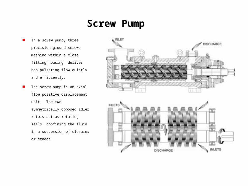
Screw Pump
In a screw pump, three precision
ground screws meshing within a close
fitting housing deliver non pulsating
flow quietly and efficiently.
The screw pump is an axial flow positive
displacement unit. The two
symmetrically opposed idler rotors act
as rotating seals, confining the fluid in a
succession of closures or stages.
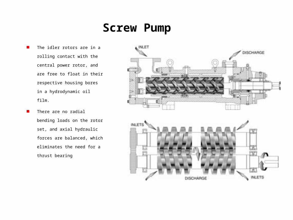
Screw Pump
The idler rotors are in a rolling contact
with the central power rotor, and are
free to float in their respective housing
bores in a hydrodynamic oil film.
There are no radial bending loads on
the rotor set, and axial hydraulic forces
are balanced, which eliminates the
need for a thrust bearing
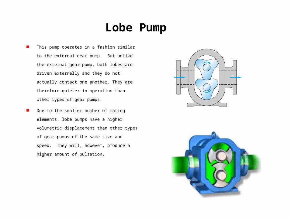
Lobe Pump
This pump operates in a fashion similar to the external gear
pump. But unlike the external gear pump, both lobes are
driven externally and they do not actually contact one
another. They are therefore quieter in operation than other
types of gear pumps.
Due to the smaller number of mating elements, lobe pumps
have a higher volumetric displacement than other types of
gear pumps of the same size and speed. They will, however,
produce a higher amount of pulsation.
Vane Pump
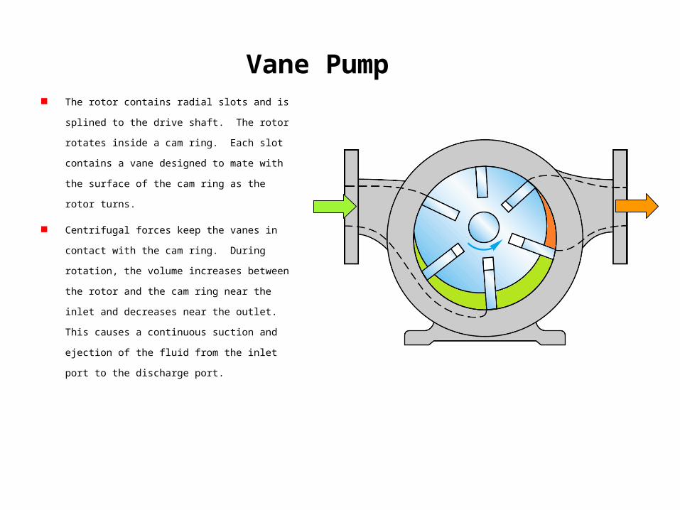
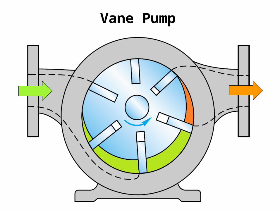
Vane Pump The rotor contains radial slots and is splined to the drive
shaft. The rotor rotates inside a cam ring. Each slot
contains a vane designed to mate with the surface of
the cam ring as the rotor turns.
Centrifugal forces keep the vanes in contact with the
cam ring. During rotation, the volume increases
between the rotor and the cam ring near the inlet and
decreases near the outlet. This causes a continuous
suction and ejection of the fluid from the inlet port to
the discharge port.
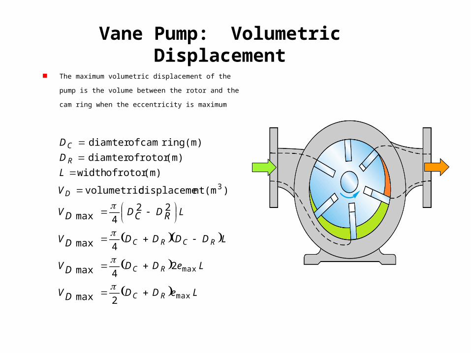
Vane Pump: Volumetric Displacement
The maximum volumetric displacement of the pump is the volume
between the rotor and the cam ring when the eccentricity is
maximum
LeDDDV
LeDDDV
LDDDDDV
LRDCDDV
V
L
D
D
RC
RC
RCRC
D
R
C
max
max
2max
24max
4max
224max
)
(m ntdisplaceme volumetric
(m) rotorof width (m) rotorof diamter
ring(m) camof diamter
3
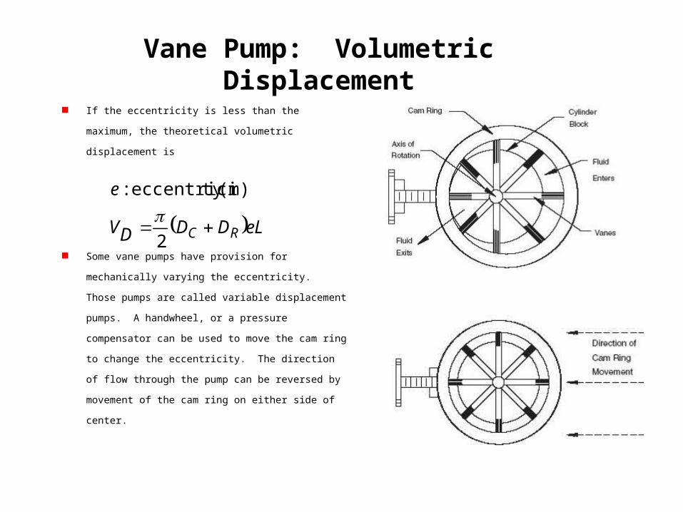
Vane Pump: Volumetric Displacement
If the eccentricity is less than the maximum, the theoretical
volumetric displacement is
Some vane pumps have provision for mechanically varying the
eccentricity. Those pumps are called variable displacement
pumps. A handwheel, or a pressure compensator can be used to
move the cam ring to change the eccentricity. The direction of
flow through the pump can be reversed by movement of the cam
ring on either side of center.
eLDDDV
e
RC 2
:
(m) tyeccentrici
Pressure Compensated Vane Pump
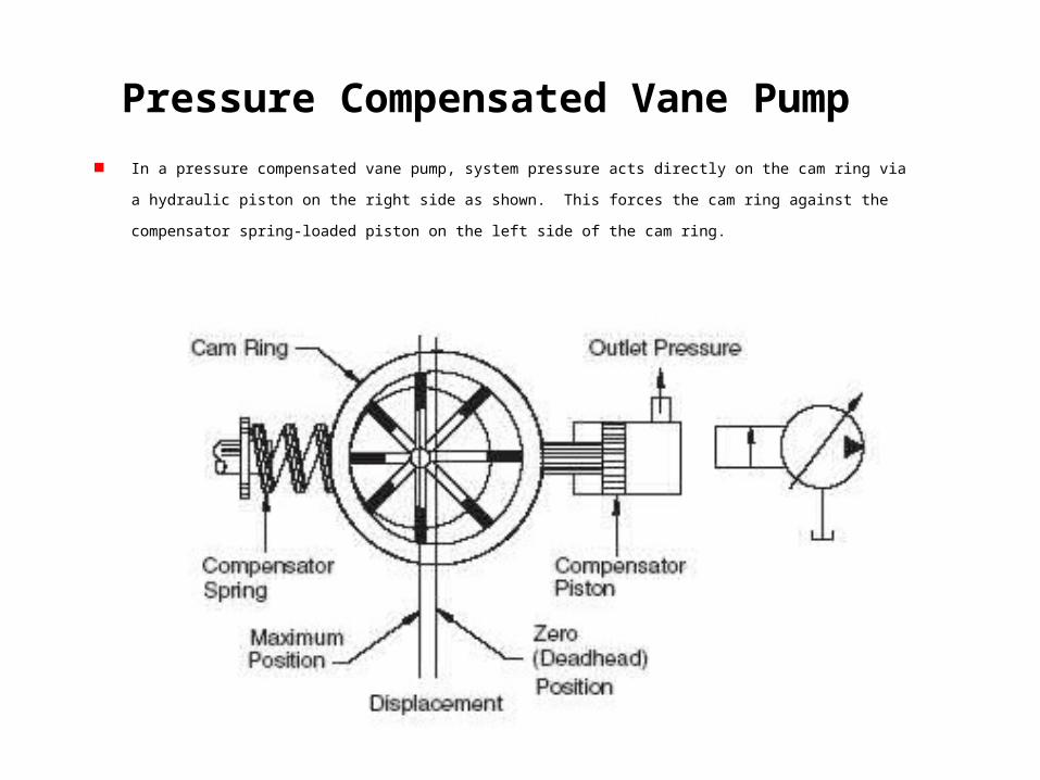
In a pressure compensated vane pump, system pressure acts directly on the cam ring via a hydraulic piston on the right side as
shown. This forces the cam ring against the compensator spring-loaded piston on the left side of the cam ring.
Pressure Compensated Vane Pump
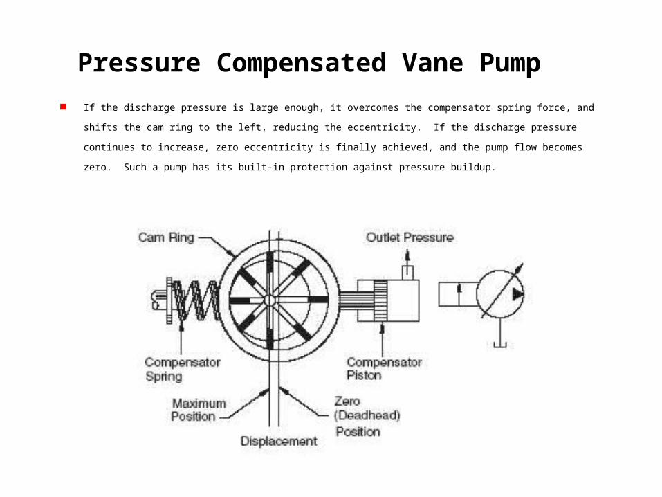
If the discharge pressure is large enough, it overcomes the compensator spring force, and shifts the cam ring to the left, reducing the
eccentricity. If the discharge pressure continues to increase, zero eccentricity is finally achieved, and the pump flow becomes zero.
Such a pump has its built-in protection against pressure buildup.
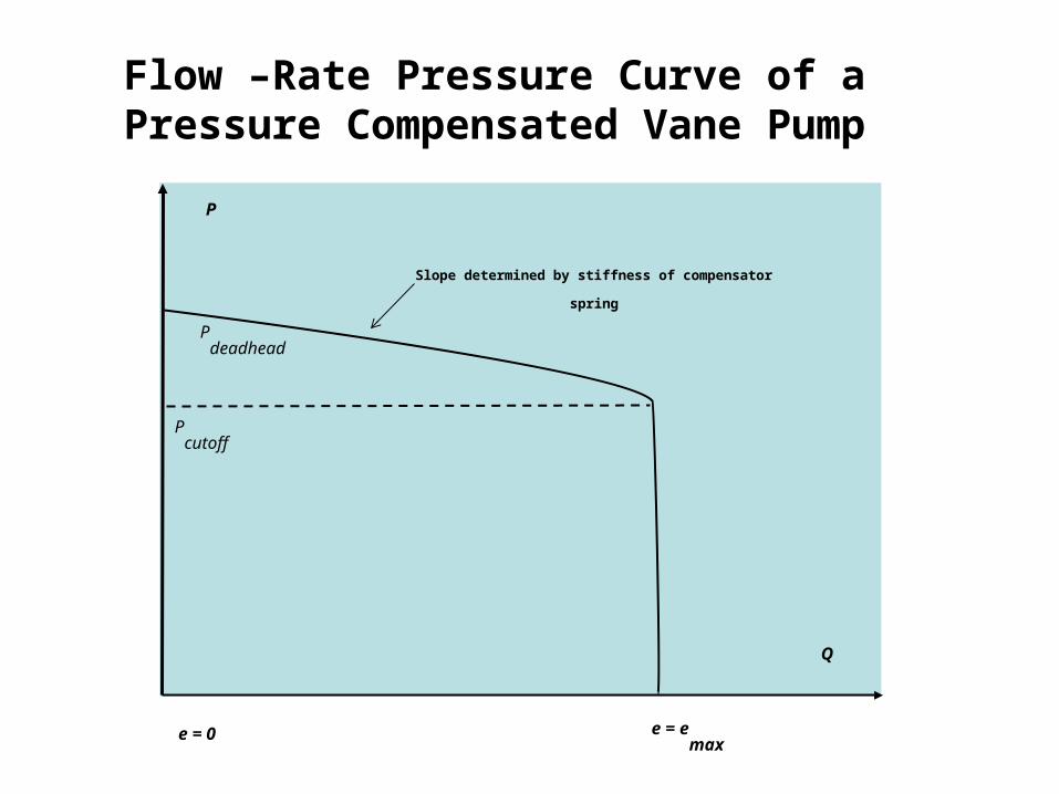
Flow –Rate Pressure Curve of a Pressure Compensated Vane Pump
Pdeadhead
Q
Slope determined by stiffness of compensator spring
e = emax
e = 0
Pcutoff
P
Pressure Compensated Vane Pump
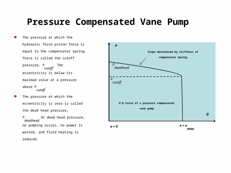
The pressure at which the hydraulic force
piston force is equal to the compensator
spring force is called the cutoff pressure,
Pcutoff
. The eccentricity is below its maximum
value at a pressure above Pcutoff
.
The pressure at which the eccentricity is zero
is called the dead head pressure, Pdeadhead.
At dead head pressure, no pumping occurs, no
power is wasted, and fluid heating is reduced.
Pdeadhead
Q
Slope determined by stiffness of compensator spring
e = emax
e = 0
Pcutoff
P
P-Q Curve of a pressure compensated vane pump
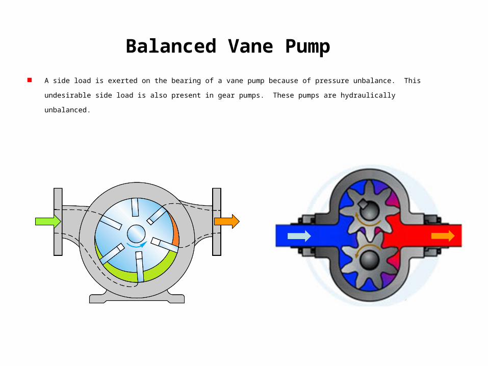
Balanced Vane Pump
A side load is exerted on the bearing of a vane pump because of pressure unbalance. This undesirable side load is also present in
gear pumps. These pumps are hydraulically unbalanced.
Balanced Vane Pump
Balanced Vane Pump
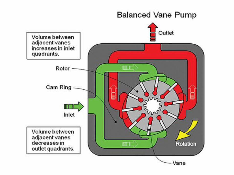
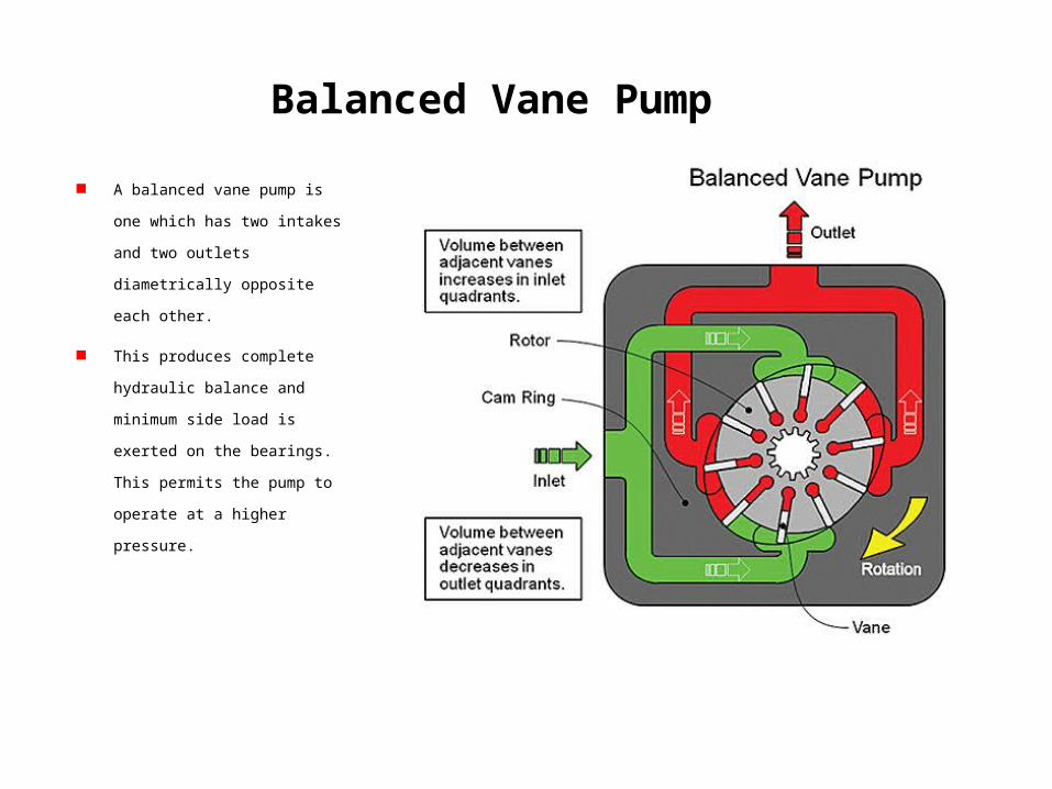
A balanced vane pump is one which
has two intakes and two outlets
diametrically opposite each other.
This produces complete hydraulic
balance and minimum side load is
exerted on the bearings. This permits
the pump to operate at a higher
pressure.
Balanced Vane Pump
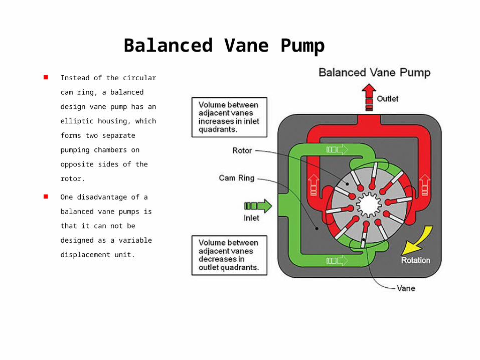
Instead of the circular cam ring, a
balanced design vane pump has
an elliptic housing, which forms
two separate pumping chambers
on opposite sides of the rotor.
One disadvantage of a balanced
vane pumps is that it can not be
designed as a variable
displacement unit.
Piston Pump Types
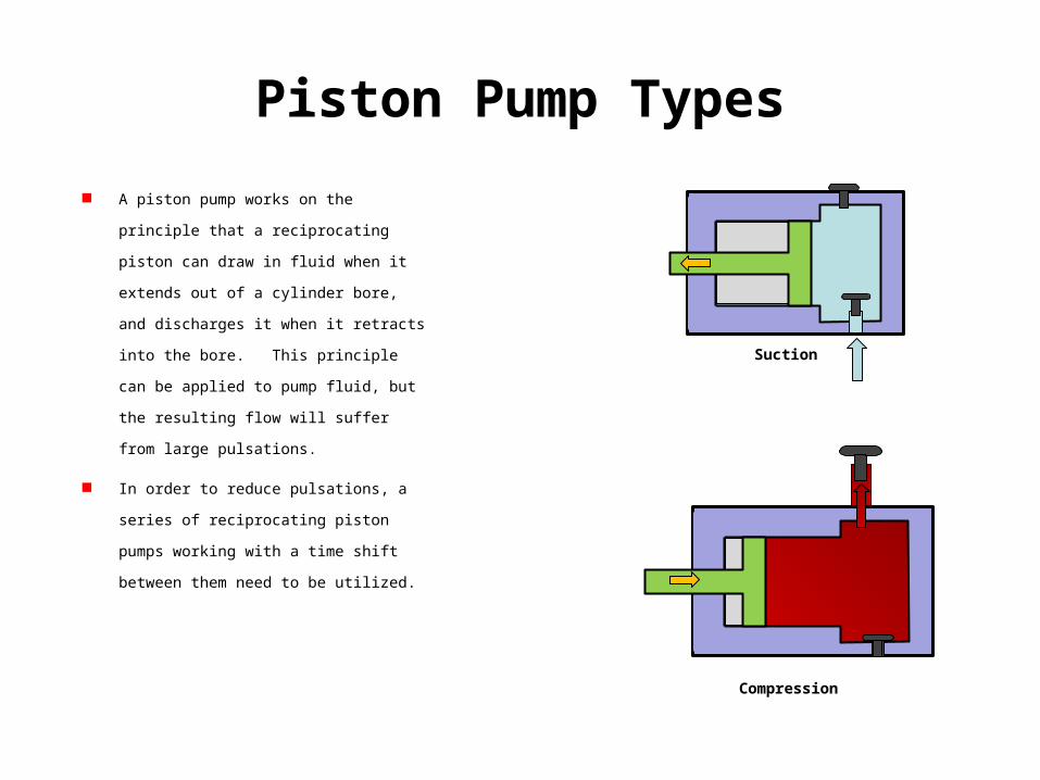
A piston pump works on the principle that a
reciprocating piston can draw in fluid when it
extends out of a cylinder bore, and discharges it
when it retracts into the bore. This principle can
be applied to pump fluid, but the resulting flow will
suffer from large pulsations.
In order to reduce pulsations, a series of
reciprocating piston pumps working with a time
shift between them need to be utilized.
Suction
Compression
Piston Pump Types
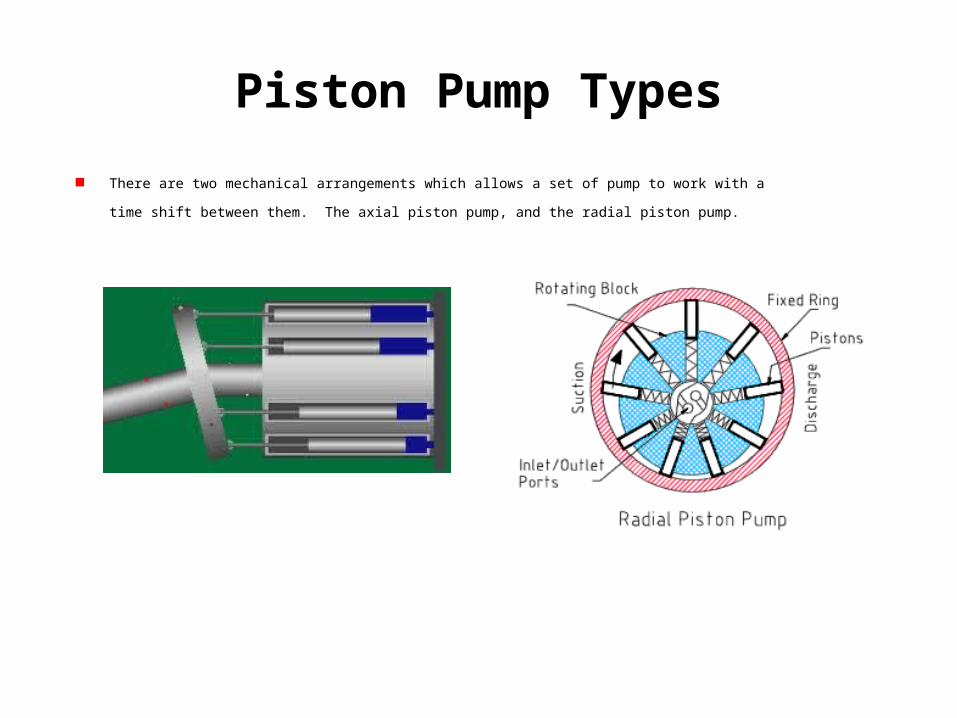
There are two mechanical arrangements which allows a set of pump to work with a time shift between them. The axial
piston pump, and the radial piston pump.
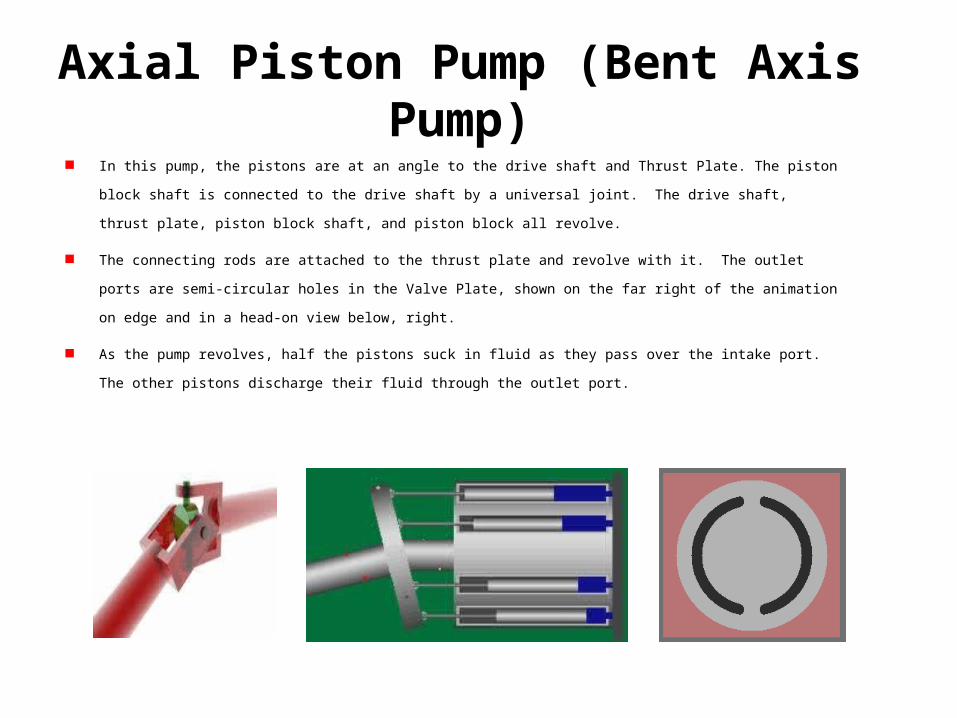
Axial Piston Pump (Bent Axis Pump) In this pump, the pistons are at an angle to the drive shaft and Thrust Plate. The piston block shaft is connected to the drive shaft
by a universal joint. The drive shaft, thrust plate, piston block shaft, and piston block all revolve.
The connecting rods are attached to the thrust plate and revolve with it. The outlet ports are semi-circular holes in the Valve Plate,
shown on the far right of the animation on edge and in a head-on view below, right.
As the pump revolves, half the pistons suck in fluid as they pass over the intake port. The other pistons discharge their fluid
through the outlet port.
Axial Piston Pump (Bent Axis Pump)
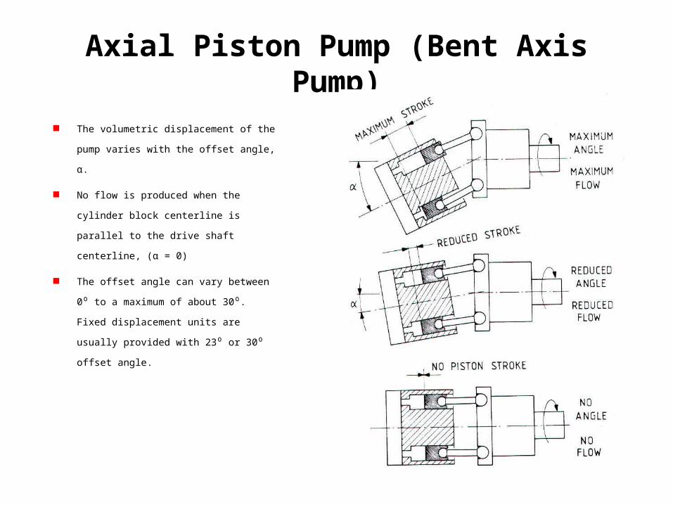
The volumetric displacement of the pump varies
with the offset angle, α.
No flow is produced when the cylinder block
centerline is parallel to the drive shaft centerline,
(α = 0)
The offset angle can vary between 0⁰ to a
maximum of about 30⁰. Fixed displacement units
are usually provided with 23⁰ or 30⁰ offset angle.
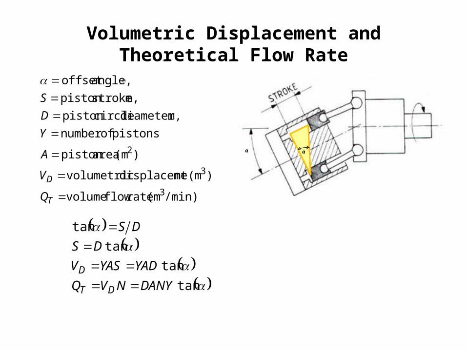
Volumetric Displacement and Theoretical Flow Rate
/min)(m rate flow volume
(m ntdisplaceme volumetric
(m area piston
pistonsof number m diameter, circle piston
m stroke, piston angle, offset
3
3
2
T
D
Q
V
A
Y
D
S
)
)
tan
tan
tan
tan
DANYNVQ
YADYASV
DS
DS
DT
D
α α
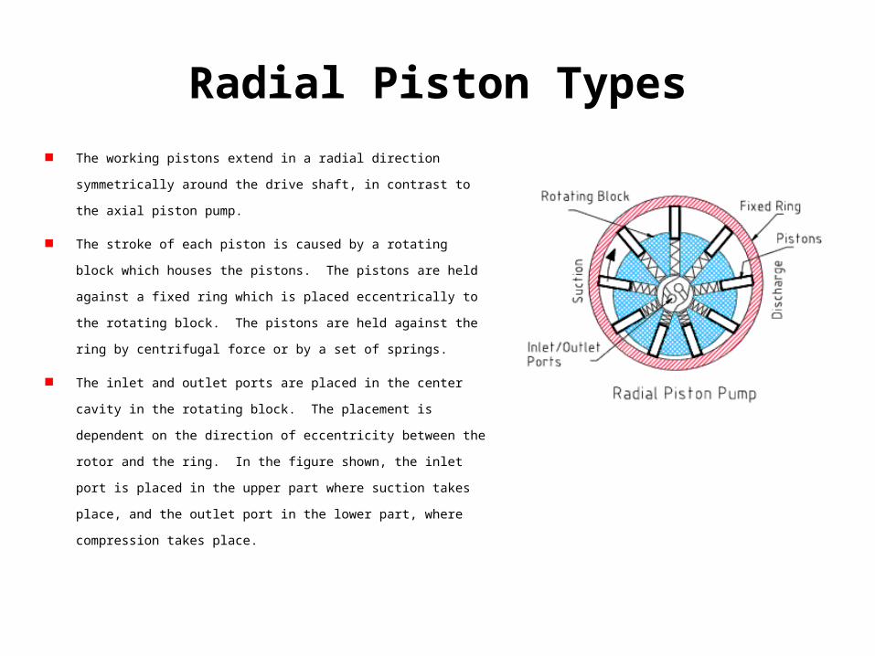
Radial Piston Types
The working pistons extend in a radial direction symmetrically around the drive
shaft, in contrast to the axial piston pump.
The stroke of each piston is caused by a rotating block which houses the pistons.
The pistons are held against a fixed ring which is placed eccentrically to the
rotating block. The pistons are held against the ring by centrifugal force or by a
set of springs.
The inlet and outlet ports are placed in the center cavity in the rotating block.
The placement is dependent on the direction of eccentricity between the rotor
and the ring. In the figure shown, the inlet port is placed in the upper part
where suction takes place, and the outlet port in the lower part, where
compression takes place.
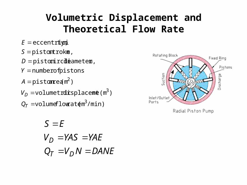
Volumetric Displacement and Theoretical Flow Rate
/min)(m rate flow volume
(m ntdisplaceme volumetric
(m area piston
pistonsof number m diameter, circle piston
m stroke, piston m ty,eccentrici
3
3
2
T
D
Q
V
A
Y
D
S
E
)
)
DANENVQ
YAEYASV
ES
DT
D
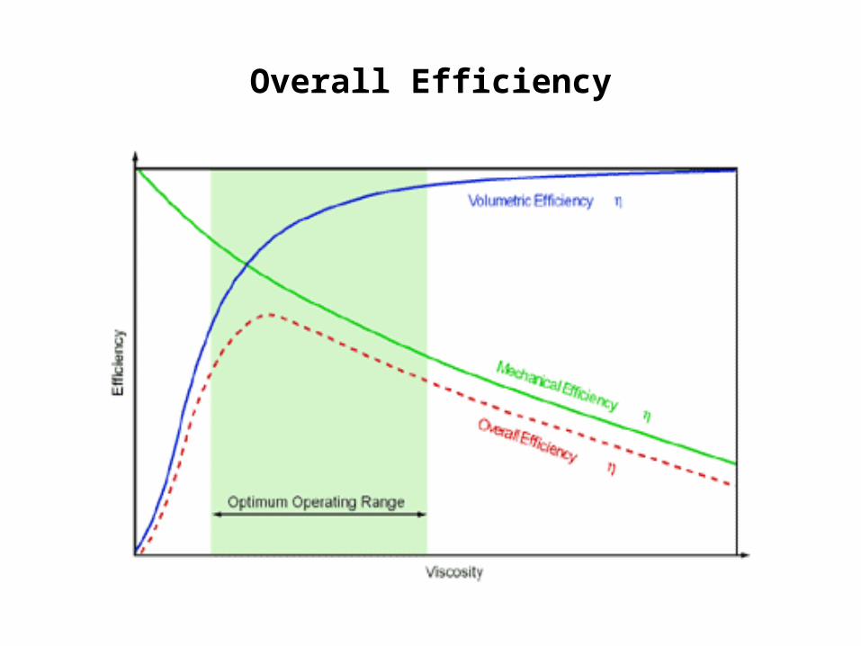
Pump Performance
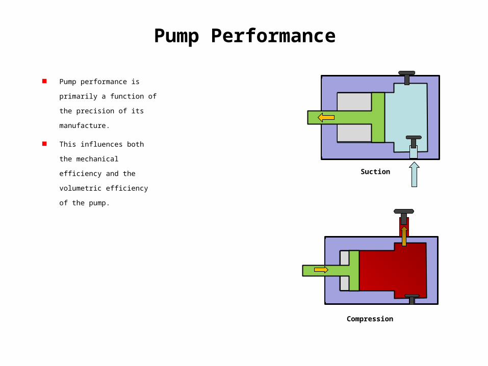
Pump Performance
Pump performance is primarily a
function of the precision of its
manufacture.
This influences both the
mechanical efficiency and the
volumetric efficiency of the pump.
Suction
Compression
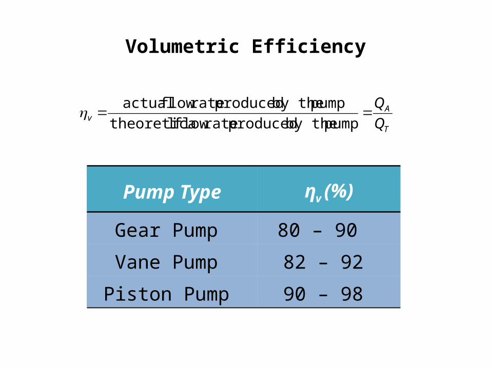
Volumetric Efficiency
T
Av Q
Q
pump by the produced rate flow ltheoretica
pump by the produced rate flow actual
Pump Type ηv (%)
Gear Pump 80 – 90
Vane Pump 82 – 92
Piston Pump 90 – 98
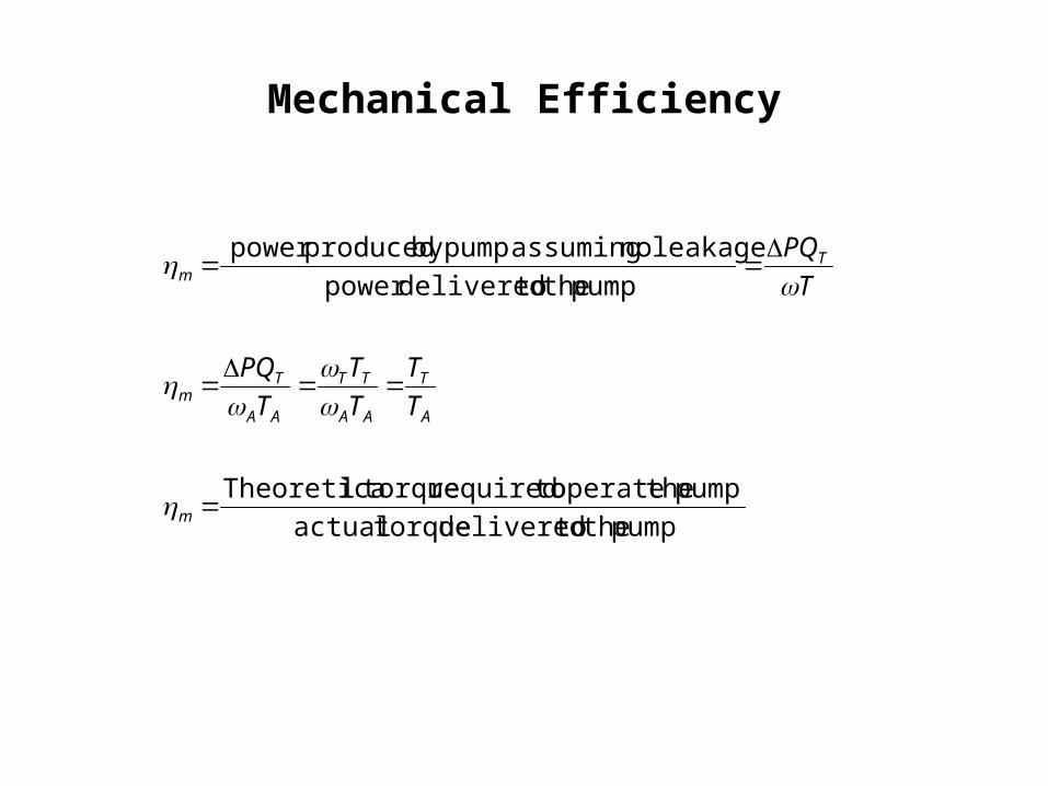
Mechanical Efficiency
pump the todelivered torqueactual
pump theoperate torequired torquelTheoretica
pump the todeliveredpower
leakage no assuming pumpby producedpower
m
A
T
AA
TT
AA
Tm
Tm
T
T
T
T
T
PQ
T
PQ
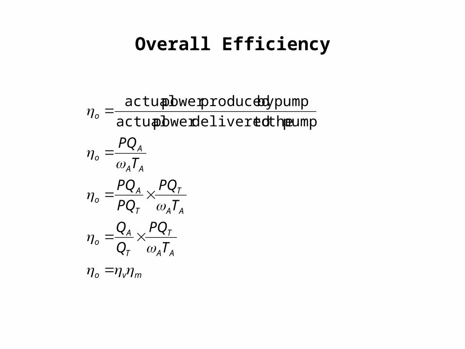
Overall Efficiency
mvo
AA
T
T
Ao
AA
T
T
Ao
AA
Ao
o
T
PQ
Q
Q
T
PQ
PQ
PQ
T
PQ
pump the todeliveredpower actual
pumpby producedpower actual
Overall Efficiency
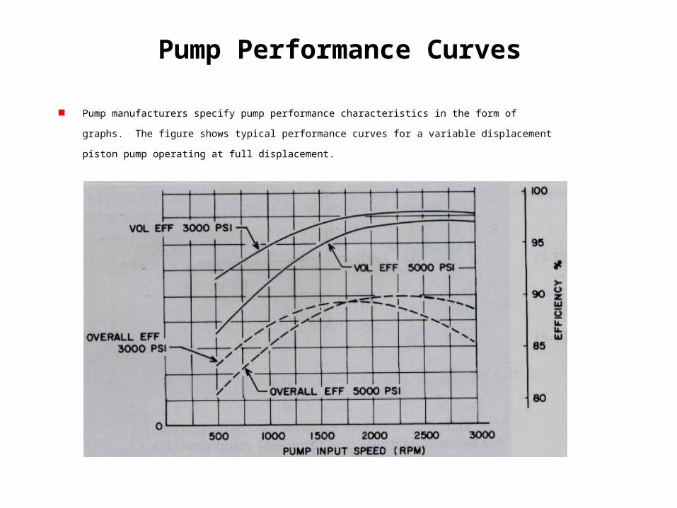
Pump Performance Curves
Pump manufacturers specify pump performance characteristics in the form of graphs. The figure shows typical
performance curves for a variable displacement piston pump operating at full displacement.
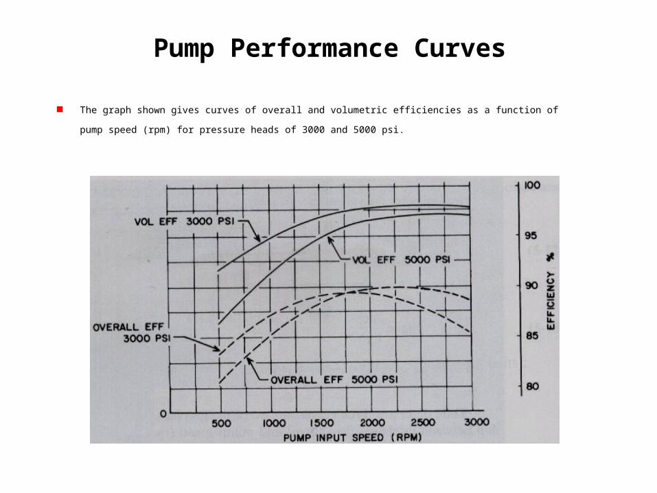
Pump Performance Curves
The graph shown gives curves of overall and volumetric efficiencies as a function of pump speed (rpm) for pressure heads of
3000 and 5000 psi.
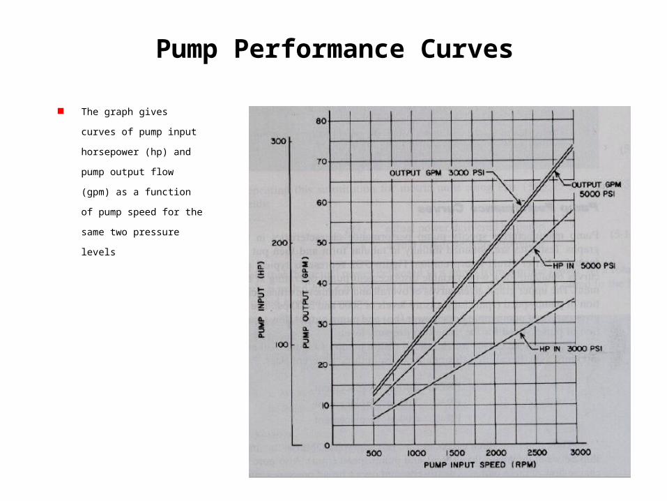
Pump Performance Curves
The graph gives curves of pump
input horsepower (hp) and
pump output flow (gpm) as a
function of pump speed for the
same two pressure levels
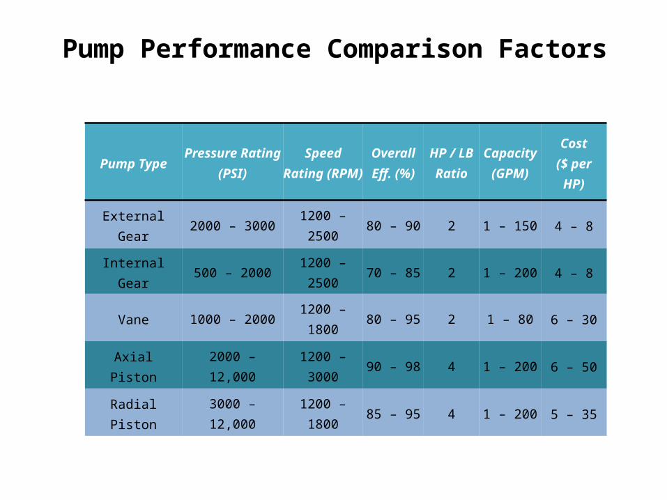
Pump Performance Comparison Factors
Pump Type Pressure Rating (PSI)
Speed Rating (RPM)
Overall Eff. (%)
HP / LB Ratio
Capacity (GPM)
Cost($ per HP)
External Gear 2000 – 3000 1200 – 2500 80 – 90 2 1 – 150 4 – 8
Internal Gear 500 – 2000 1200 – 2500 70 – 85 2 1 – 200 4 – 8
Vane 1000 – 2000 1200 – 1800 80 – 95 2 1 – 80 6 – 30
Axial Piston 2000 – 12,000 1200 – 3000 90 – 98 4 1 – 200 6 – 50
Radial Piston 3000 – 12,000 1200 – 1800 85 – 95 4 1 – 200 5 – 35
Pump Noise
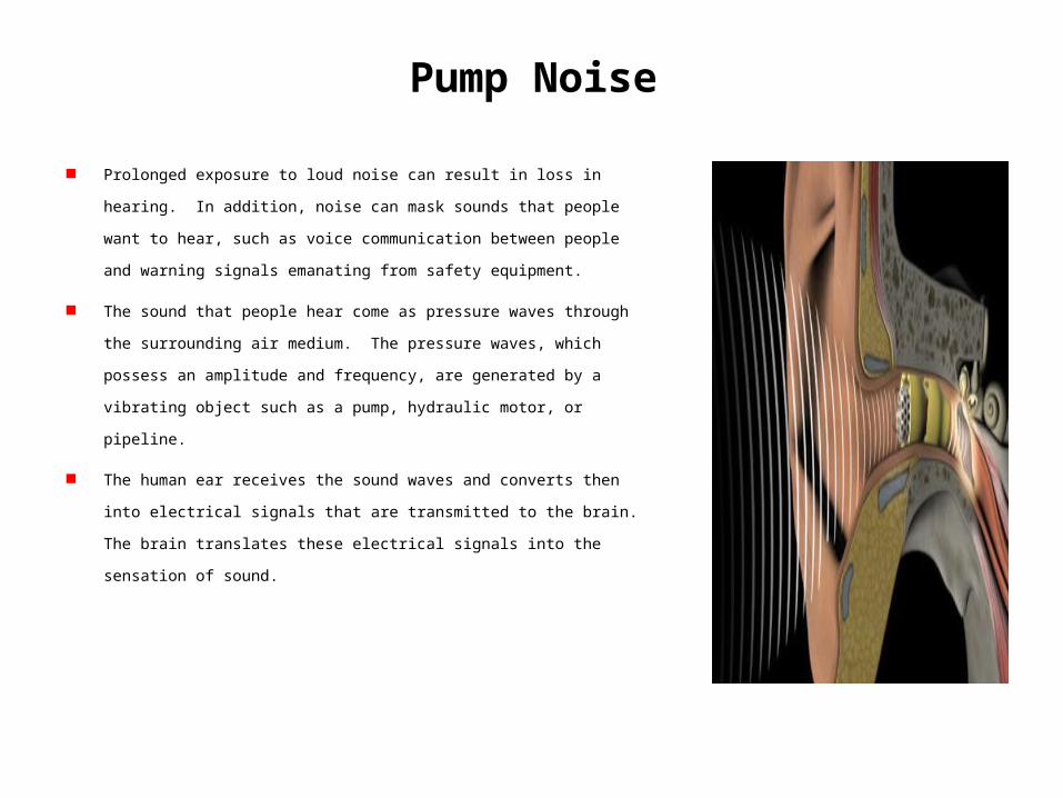
Prolonged exposure to loud noise can result in loss in hearing. In addition, noise can
mask sounds that people want to hear, such as voice communication between people
and warning signals emanating from safety equipment.
The sound that people hear come as pressure waves through the surrounding air
medium. The pressure waves, which possess an amplitude and frequency, are
generated by a vibrating object such as a pump, hydraulic motor, or pipeline.
The human ear receives the sound waves and converts then into electrical signals that
are transmitted to the brain. The brain translates these electrical signals into the
sensation of sound.
Sound Intensity Levels (dB)
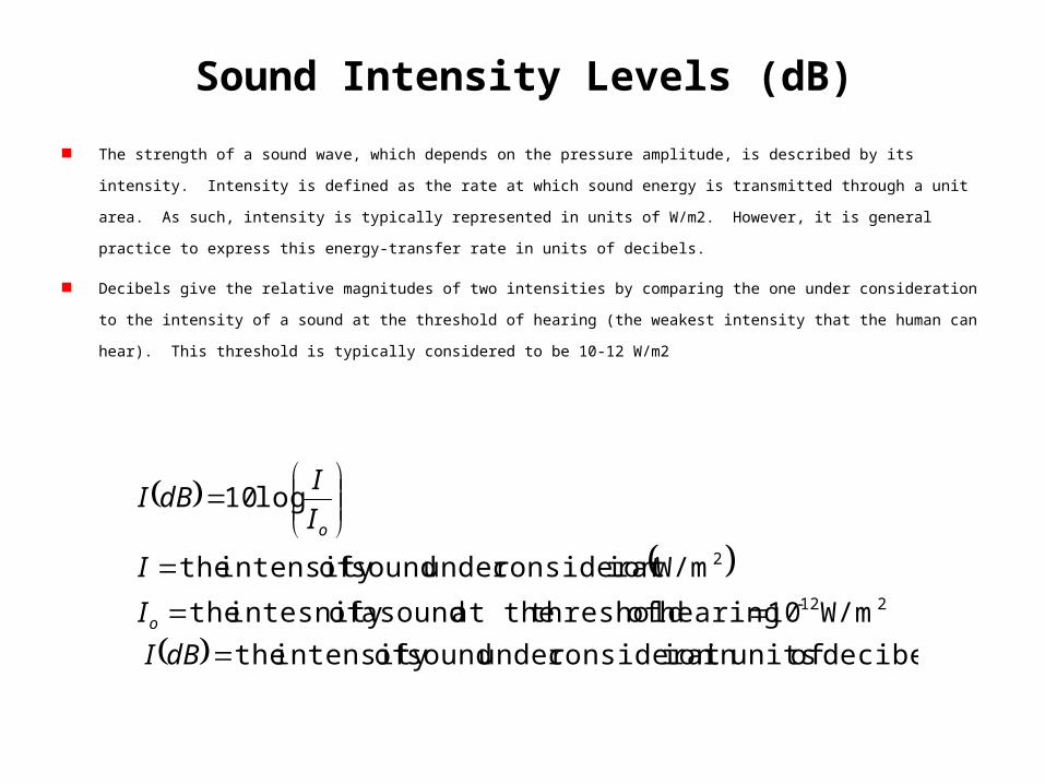
The strength of a sound wave, which depends on the pressure amplitude, is described by its intensity. Intensity is defined as the rate at which
sound energy is transmitted through a unit area. As such, intensity is typically represented in units of W/m2. However, it is general practice to
express this energy-transfer rate in units of decibels.
Decibels give the relative magnitudes of two intensities by comparing the one under consideration to the intensity of a sound at the threshold
of hearing (the weakest intensity that the human can hear). This threshold is typically considered to be 10-12 W/m2
decibels of unitsin ion consideratunder sound ofintensity the
W/m10 hearing of thresholdat the sound a ofintesnity the
W/mion consideratunder sound ofintensity the
log10
212-
2
dBI
I
I
I
IdBI
o
o
Sound Intensity Levels (dB)
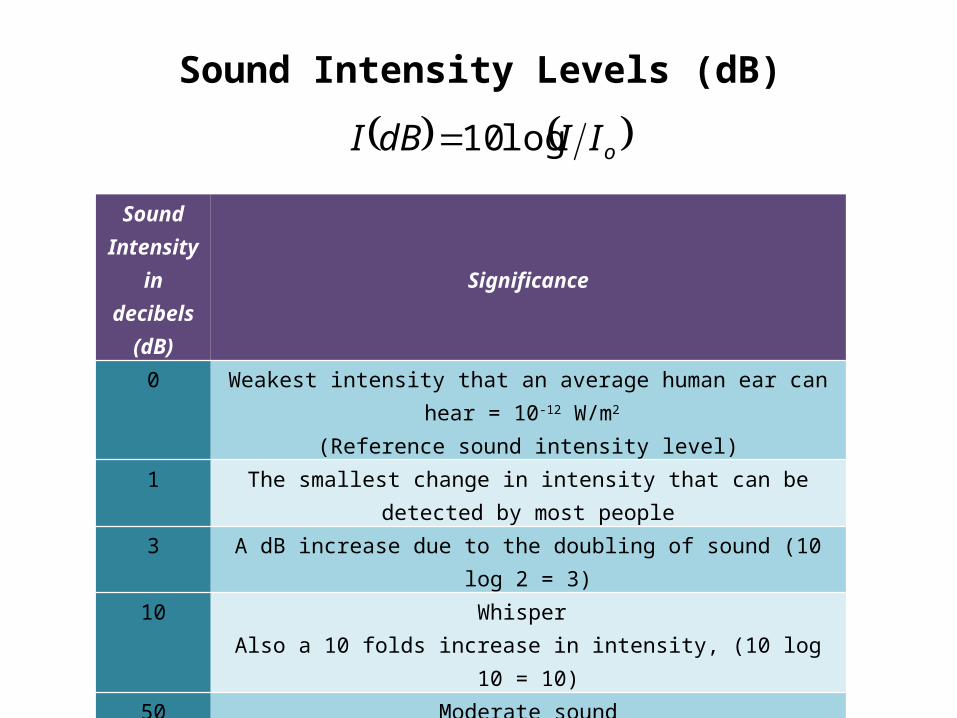
oIIdBI log10
Sound Intensity in
decibels (dB)
Significance
0 Weakest intensity that an average human ear can hear = 10-12 W/m2 (Reference sound intensity level)
1 The smallest change in intensity that can be detected by most people
3 A dB increase due to the doubling of sound (10 log 2 = 3)
10 Whisper Also a 10 folds increase in intensity, (10 log 10 = 10)
50 Moderate sound
90 OSHA maximum sound level that a person may be exposed to during an 8-hr period in the workplace
100 Noisy city traffic>120 Produces pain and may cause permanent loss of hearing
Control of Pump Noise
Noise reduction can be accomplished as follows:
Source treatment: treat misaligned pump motor/coupling,
improperly installed pump/mounting plate, cavitation,i excess
pump speed or pressure
Modify components connected to the primary source of noise,
e.g., clamping hydraulic piping at specifically located supports.
Use sound absorbing material in nearby screens or partitions.
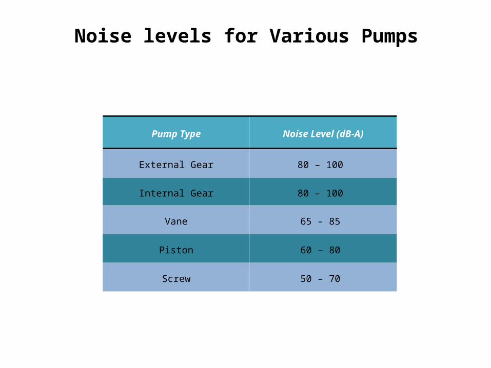
Noise levels for Various Pumps
Pump Type Noise Level (dB-A)
External Gear 80 – 100
Internal Gear 80 – 100
Vane 65 – 85
Piston 60 – 80
Screw 50 – 70
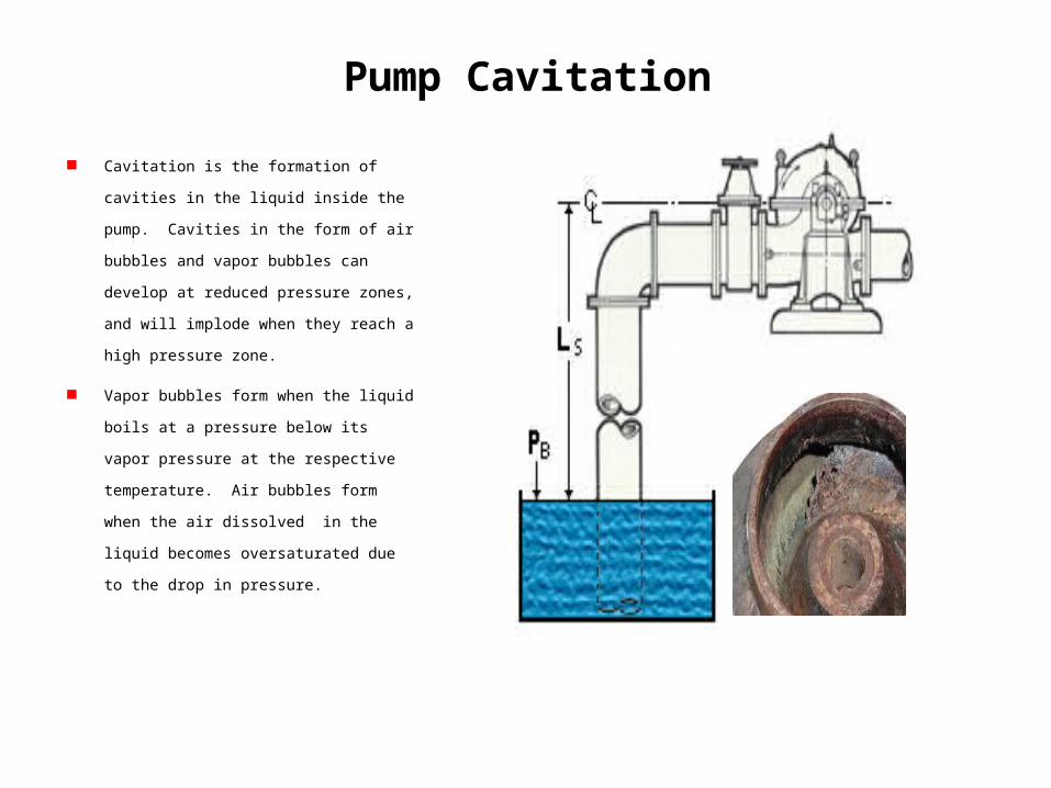
Pump Cavitation
Cavitation is the formation of cavities in the liquid
inside the pump. Cavities in the form of air
bubbles and vapor bubbles can develop at reduced
pressure zones, and will implode when they reach
a high pressure zone.
Vapor bubbles form when the liquid boils at a
pressure below its vapor pressure at the respective
temperature. Air bubbles form when the air
dissolved in the liquid becomes oversaturated due
to the drop in pressure.
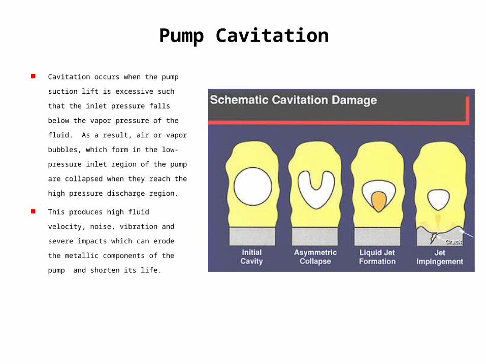
Pump Cavitation
Cavitation occurs when the pump suction lift is
excessive such that the inlet pressure falls below
the vapor pressure of the fluid. As a result, air or
vapor bubbles, which form in the low-pressure
inlet region of the pump are collapsed when they
reach the high pressure discharge region.
This produces high fluid velocity, noise, vibration
and severe impacts which can erode the metallic
components of the pump and shorten its life.
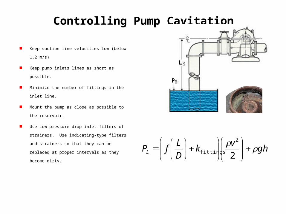
Controlling Pump Cavitation
Keep suction line velocities low (below 1.2 m/s)
Keep pump inlets lines as short as possible.
Minimize the number of fittings in the inlet line.
Mount the pump as close as possible to the reservoir.
Use low pressure drop inlet filters of strainers. Use
indicating-type filters and strainers so that they can be
replaced at proper intervals as they become dirty.
ghv
kD
LfPL
2
2
fittings
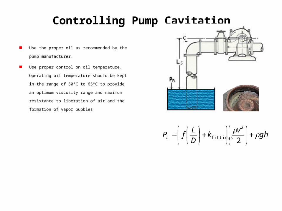
Controlling Pump Cavitation
Use the proper oil as recommended by the pump
manufacturer.
Use proper control on oil temperature. Operating oil
temperature should be kept in the range of 50°C to 65°C to
provide an optimum viscosity range and maximum
resistance to liberation of air and the formation of vapor
bubbles
ghv
kD
LfPL
2
2
fittings
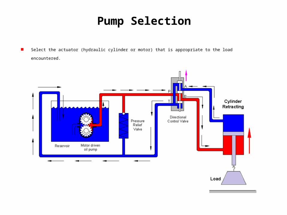
Pump Selection
Select the actuator (hydraulic cylinder or motor) that is appropriate to the load encountered.

Pump Selection
Determine the flow rate requirements. This involves calculating the flow rate necessary to drive the actuator to move the load through
a specified distance within a given time limit.

Pump Selection
Select the system pressure. This ties in with the actuator size and the magnitude of resistive forces produced by external loads on the
system. Also involved here the total amount of power to be delivered by the pump.

Pump Selection
Determine the pump speed and select the prime mover. This together with the flow rate calculation, determines the pump size
(volumetric displacement)

Pump Selection
Select the pump type based on the application (gear, vane or piston pump, and fixed or variable displacement)

Pump Selection
Select the reservoir and the associated plumbing, including piping, valving, filters and strainers, and other miscellaneous components.

Pump Selection
Consider factors such as pump noise levels, power loss, need for a heat exchanger due to generated heat, pump wear and scheduled
maintenance service to provide a desired life of the total system.
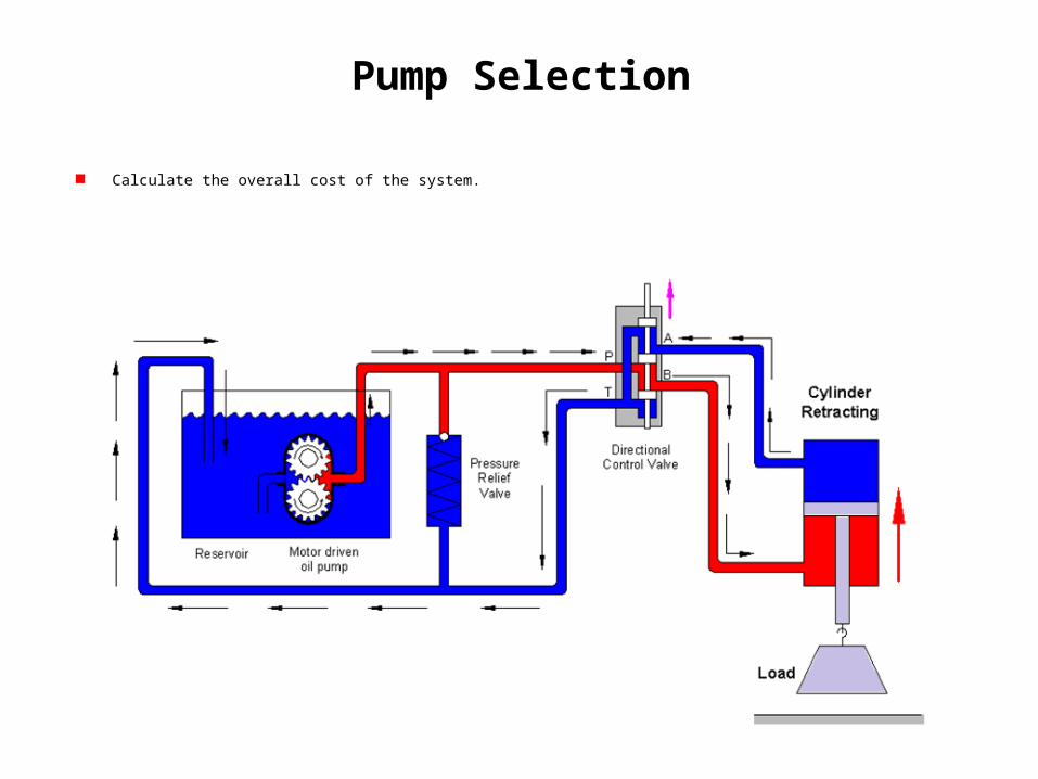
Pump Selection
Calculate the overall cost of the system.