Embed Size (px)
Citation preview
1
Hydraulic pump HP-1
FU
2163000912E
N
Technical data:
Permissible operating temperature: -15°C - + 80°C
Lubricant: Greases up to NLGI-Kl. 2
(excluding solid lubricants)
Mineral oils up to 40 mm /s (cSt)
Number of outlets: max. 3
Delivery rate per outlet: max. 0.12 cm³/Stroke
Stirrer direction: clockwise
Mounting position: Reservoir in vertical position
Drive type: Hydraulic motor with worm wheel
Displacement: min. 6 l/min.
max. 17.2 l/min.
(corresponds 1400 - 4000 min )
Ratio of the worm gear: 150:1
Oil inlet pressure P1: min. 30 bar
max. 200 bar
Oil outlet pressure P2: max. 1,5 bar
Reservoirs size:
Transparent reservoirs: 1,9; 2,5; 4; and 8 kg
Steel reservoirs: 2 and 4 kg
Order-No.: refer ordering key
2
-1
The BEKA-MAX central lubrication pump model HP-1 is
hydraulic actuated and has up to a maximum of 3
independently operating lubricant outlets.Aseparate pump
unit is required for each outlet.
Three pump elements with different flow rates are
available, as well as a flow-adjustable pump element (see
page 6).
These pumps enable the delivery of commercial lubricants
up to NLGI-class 2 at a working pressure of maximum 280
bar (pressure relief valve setting).
Filling the pump is made by a grease form nipple or as a
fast-filling-coupling.
The pump is protected by the pressure relief valve at the
pump element (up to max. 280 bar).
This enables the grease quantity to be adapted to
the requirement of the individual progressive distributor
circuits.
Pressure relief
valve
Pressure outlet
Filling nipple
Ventilation
Throttle unit R 3/8”
Inlet
Outlet
Leak connection G 1/4”
Attention: pressureless
Type 1
Type 2
Throttle valve
0438000054
Double fitting G1/4” to G1/4”Reduction G3/8” to G1/4”
G 1
/4”
approx. 84.3
Leak connection
G 1/4”
Attention: pressureless
Inlet
OutletG 3/8”
G 3/8”
P1
P1
P2
P2
XX
© B
EK
A2012 A
ll rights
rese
rved!
Subje
ct to a
ltera
tions!
BEKA Nederland B.V. [email protected]
tel. +31 168 371 538fax +31 168 338 329
Wagenmakerij 114762 AV Zevenbergen
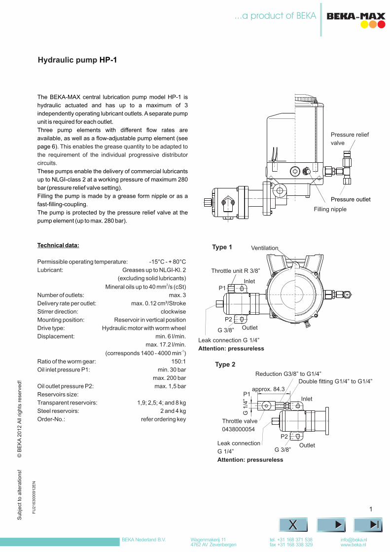
Method of Operation
This eccentricity
effects the suction and pressure strokes of the delivery piston (7), whereby the integrated non-return valve (8) prevents the
delivery media from being sucked back out of the main line.
The stirrer (2) pushes the lubricant out of the supply container (1) through a screen (4), which reduces any air bubbles, to the
suction area in the pump housing (3).
Filling of the storage tank (1) is effected via the conical grease nipple. The pressure relief value (9), is pre-set to 280 bar
operating pressure, to provide protection for the pump and piping system.
A hydraulic motor (10) continually operates over a worm gear the eccentric cam (5) and pressure ring (6).
Hydraulic pump HP-1
Method of Operation
8
9
3
7
10
6
5
4
2
1
2
Pump element is drawing in: Pump element is delivering:
Su
bje
ct to a
ltera
tions!
© B
EK
A2012 A
ll rights
rese
rved!
Subje
ct to a
ltera
tions!
BEKA Nederland B.V. [email protected]
tel. +31 168 371 538fax +31 168 338 329
Wagenmakerij 114762 AV Zevenbergen
Hydraulic pump HP-1
Installation dimensions
Dia. 151
207
175
107
299
Dia. 9.3
3
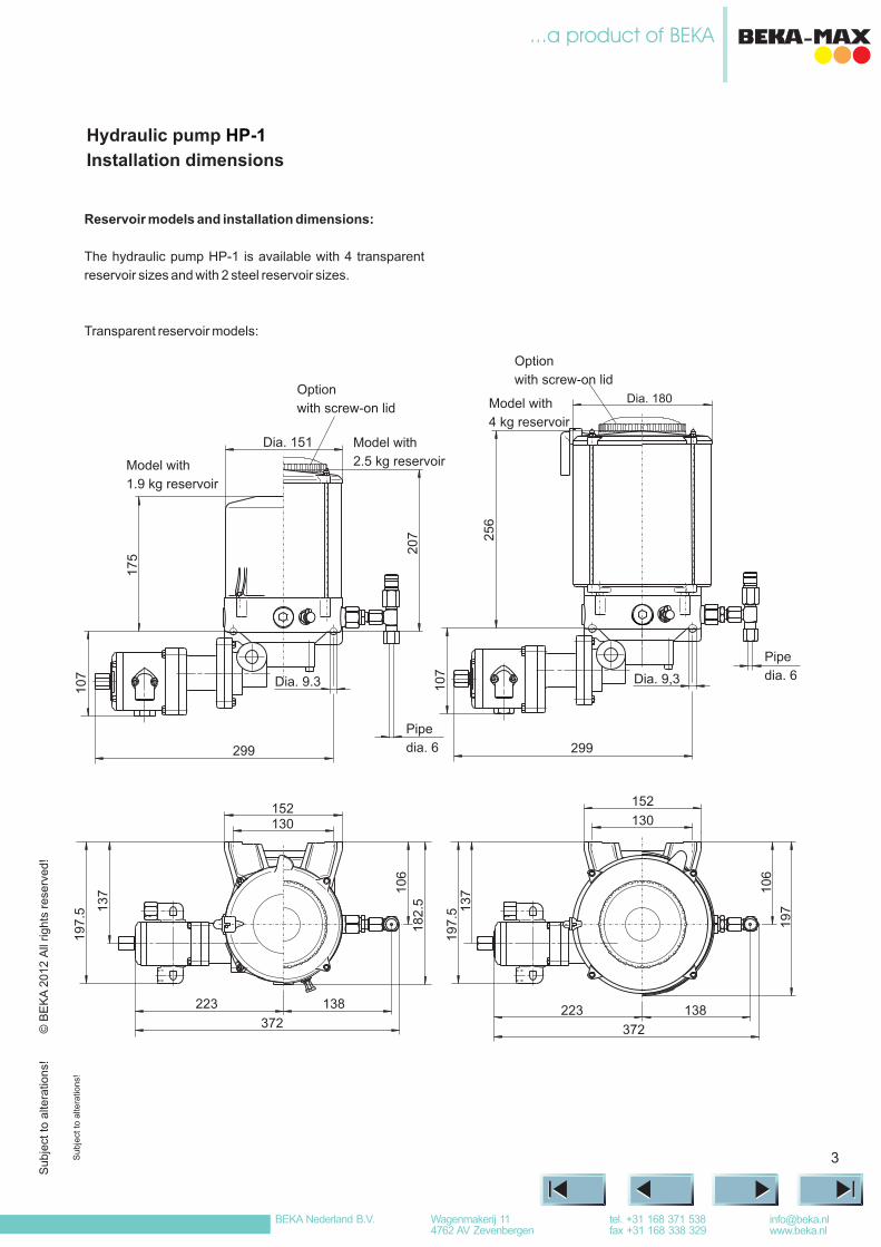
Reservoir models and installation dimensions:
The hydraulic pump HP-1 is available with 4 transparent
reservoir sizes and with 2 steel reservoir sizes.
Transparent reservoir models:
Model with
1.9 kg reservoir
Model with
2.5 kg reservoir
Option
with screw-on lid
Pipe
dia. 6
Su
bje
ct to a
ltera
tions!
Model with
4 kg reservoir
Option
with screw-on lid
Dia. 180
256
Pipe
dia. 6
107
299
Dia. 9,3
130152
106
182.5
138223
372
137
197.5
130
152
106
197
138
372
223
137
197.5
© B
EK
A2012 A
ll rights
rese
rved!
Subje
ct to a
ltera
tions!
BEKA Nederland B.V. [email protected]
tel. +31 168 371 538fax +31 168 338 329
Wagenmakerij 114762 AV Zevenbergen
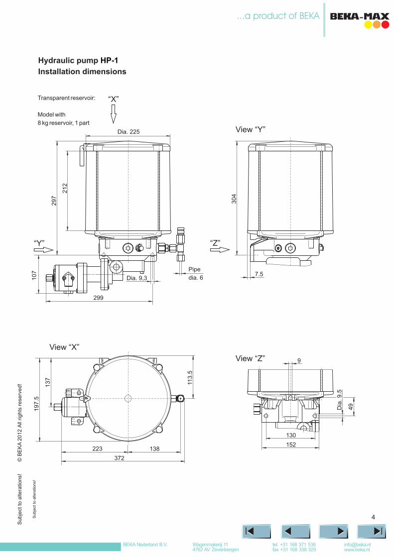
Model with
8 kg reservoir, 1 part
4
Hydraulic pump
Installation dimensions
HP-1
“X”
“Y”304
7.5
“Z”
9
Dia
. 9.5
49
130
152
Transparent reservoir:
View “Y”
View “Z”
Su
bje
ct to a
ltera
tions!
Dia. 225
212
Dia. 9,3
299
297
107 Pipe
dia. 6
View “X”
113.5
137
197.5
138
372
223
© B
EK
A2012 A
ll rights
rese
rved!
Subje
ct to a
ltera
tions!
BEKA Nederland B.V. [email protected]
tel. +31 168 371 538fax +31 168 338 329
Wagenmakerij 114762 AV Zevenbergen
5
“X”
Ø150
184
304
Ø9.3107
299
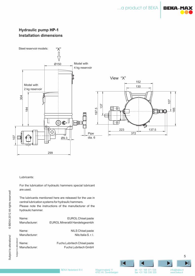
Steel reservoir models:
Hydraulic pump
Installation dimensions
HP-1
View “X”
Model with
4 kg reservoir
Model with
2 kg reservoir
Pipe
dia. 6
Su
bje
ct to a
ltera
tions!
Lubricants:
For the lubrication of hydraulic hammers special lubricant
are used.
The lubricants mentioned here are released for the use in
central lubrication systems for hydraulic hammers.
Please note the instructions of the manufacturer of the
hydraulic hammer.
Name: EUROL
Manufacturer: EUROLMineralöl Handelsgesmbh
Chisel paste
Name: NILS Chisel paste
Manufacturer: Nils Italia S. r. l.
Name: Fuchs Lubritech Chisel paste
Manufacturer: Fuchs Lubritech GmbH
130
152
137.5
107
185
223372
137
197.5
© B
EK
A2012 A
ll rights
rese
rved!
Subje
ct to a
ltera
tions!
BEKA Nederland B.V. [email protected]
tel. +31 168 371 538fax +31 168 338 329
Wagenmakerij 114762 AV Zevenbergen
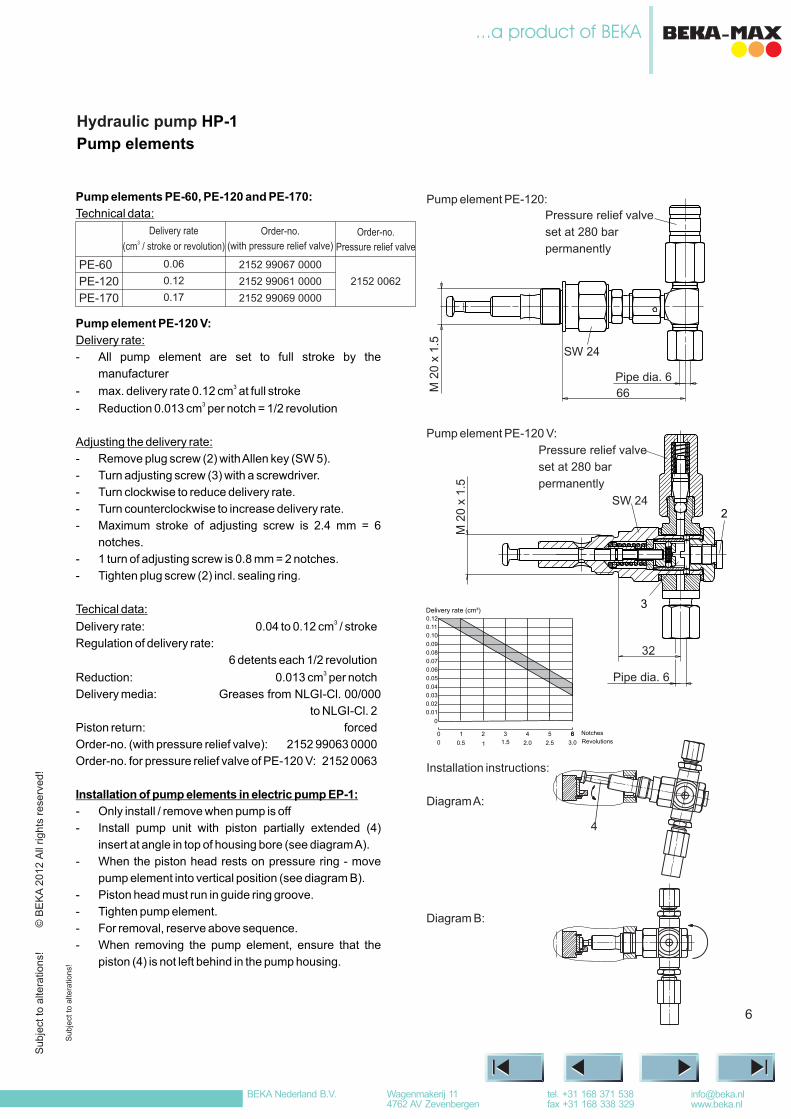
Pump element PE-120:
Pump element PE-120 V:
Installation instructions:
DiagramA:
Diagram B:
6
Hydraulic pump HP-1
Pump elements
1 3.0
0.12
0.11
0.10
0.09
0.08
0.07
0.06
0.05
0.04
0.03
0.02
0.01
0
2.0 2.5
Delivery rate (cm³)
0 0.5 1.5
1 3 52 40 Notches
Revolutions66
Pressure relief valve
set at 280 bar
permanently
SW 24
Pipe dia. 6
M 2
0 x
1.5
2
3
32
M 2
0 x
1.5
Pressure relief valve
set at 280 bar
permanently
SW 24
Pipe dia. 6
66
4
Pump elements PE-60, PE-120 and PE-170:
Technical data:
Pump element PE-120 V:
Delivery rate:
- All pump element are set to full stroke by the
manufacturer
- max. delivery rate 0.12 cm at full stroke
- Reduction 0.013 cm per notch = 1/2 revolution
3
3
Adjusting the delivery rate:
- Remove plug screw (2) withAllen key (SW 5).
- Turn adjusting screw (3) with a screwdriver.
- Turn clockwise to reduce delivery rate.
- Turn counterclockwise to increase delivery rate.
- Maximum stroke of adjusting screw is 2.4 mm = 6
notches.
- 1 turn of adjusting screw is 0.8 mm = 2 notches.
- Tighten plug screw (2) incl. sealing ring.
Techical data:
Delivery rate: 0.04 to 0.12 cm / stroke
Regulation of delivery rate:
6 detents each 1/2 revolution
Reduction: 0.013 cm per notch
Delivery media: Greases from NLGI-Cl. 00/000
to NLGI-Cl. 2
Piston return: forced
Order-no. (with pressure relief valve): 2152 99063 0000
Order-no. for pressure relief valve of PE-120 V: 2152 0063
3
3
Installation of pump elements in electric pump EP-1:
- Only install / remove when pump is off
- Install pump unit with piston partially extended (4)
insert at angle in top of housing bore (see diagramA).
- When the piston head rests on pressure ring - move
pump element into vertical position (see diagram B).
- Piston head must run in guide ring groove.
- Tighten pump element.
- For removal, reserve above sequence.
- When removing the pump element, ensure that the
piston (4) is not left behind in the pump housing.
PE-60
PE-120
PE-170
Delivery rate
(cm / stroke or revolution)3
Order-no.
(with pressure relief valve)Order-no.
Pressure relief valve
0.06
0.12
0.17
2152 99061 0000
2152 99067 0000
2152 99069 0000
2152 0062
Su
bje
ct to a
ltera
tions!
© B
EK
A2012 A
ll rights
rese
rved!
Subje
ct to a
ltera
tions!
BEKA Nederland B.V. [email protected]
tel. +31 168 371 538fax +31 168 338 329
Wagenmakerij 114762 AV Zevenbergen
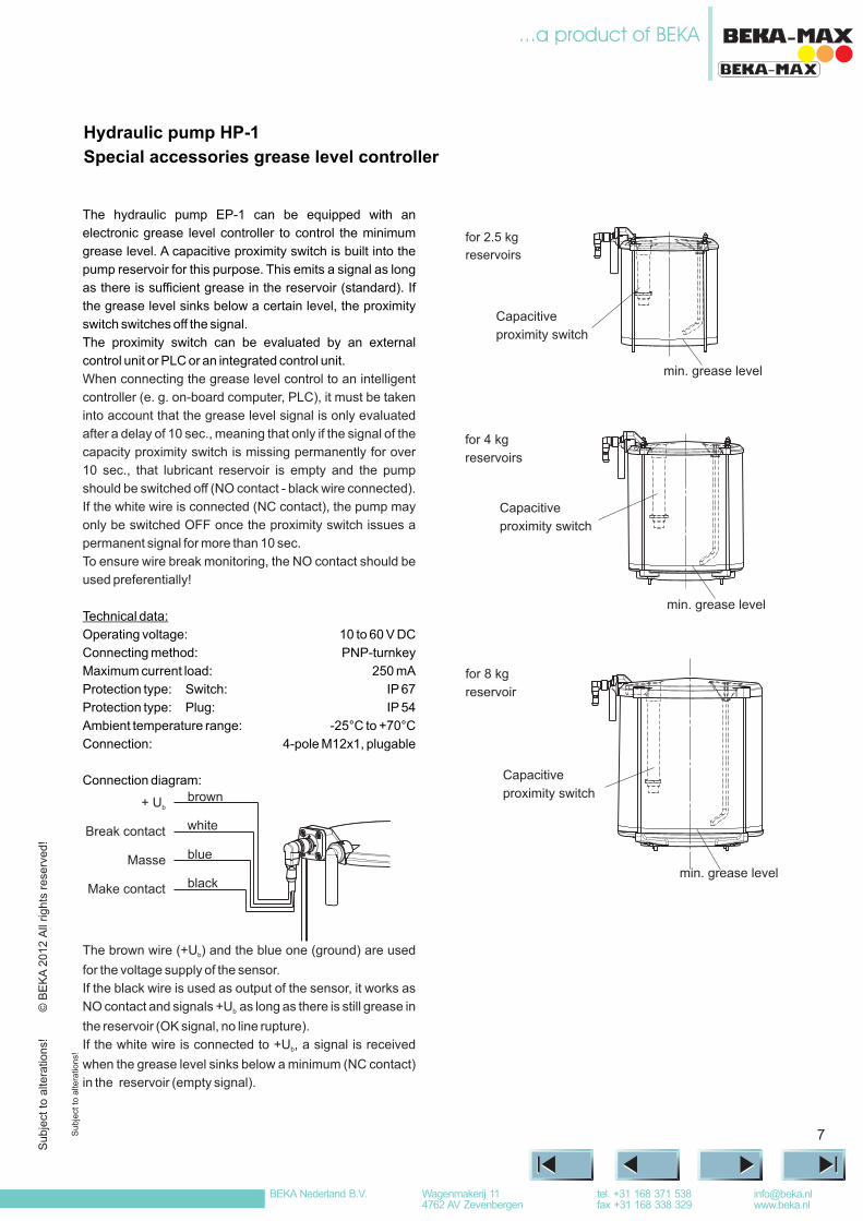
The hydraulic pump EP-1 can be equipped with an
electronic grease level controller to control the minimum
grease level. A capacitive proximity switch is built into the
pump reservoir for this purpose. This emits a signal as long
as there is sufficient grease in the reservoir (standard). If
the grease level sinks below a certain level, the proximity
switch switches off the signal.
The proximity switch can be evaluated by an external
control unit or PLC or an integrated control unit.
When connecting the grease level control to an intelligent
controller (e. g. on-board computer, PLC), it must be taken
into account that the grease level signal is only evaluated
after a delay of 10 sec., meaning that only if the signal of the
capacity proximity switch is missing permanently for over
10 sec., that lubricant reservoir is empty and the pump
should be switched off (NO contact - black wire connected).
If the white wire is connected (NC contact), the pump may
only be switched OFF once the proximity switch issues a
permanent signal for more than 10 sec.
To ensure wire break monitoring, the NO contact should be
used preferentially!
Technical data:
Operating voltage: 10 to 60 V DC
Connecting method: PNP-turnkey
Maximum current load: 250 mA
Protection type: Switch: IP 67
Ambient temperature range: -25°C to +70°C
Protection type: Plug: IP 54
Connection: 4-pole M12x1, plugable
The brown wire (+U ) and the blue one (ground) are used
for the voltage supply of the sensor.
If the black wire is used as output of the sensor, it works as
NO contact and signals +U as long as there is still grease in
the reservoir (OK signal, no line rupture).
If the white wire is connected to +U , a signal is received
when the grease level sinks below a minimum (NC contact)
in the reservoir (empty signal).
b
b
b
Hydraulic pump HP-1
Special accessories grease level controller
7Su
bje
ct to a
ltera
tions!
for 2.5 kg
reservoirs
Capacitive
proximity switch
min. grease level
for 4 kg
reservoirs
Capacitive
proximity switch
min. grease level
for 8 kg
reservoir
min. grease level
Capacitive
proximity switchConnection diagram:
brown
white
blue
blackMake contact
Masse
Break contact
+ Ub
© B
EK
A2012 A
ll rights
rese
rved!
Subje
ct to a
ltera
tions!
BEKA Nederland B.V. [email protected]
tel. +31 168 371 538fax +31 168 338 329
Wagenmakerij 114762 AV Zevenbergen
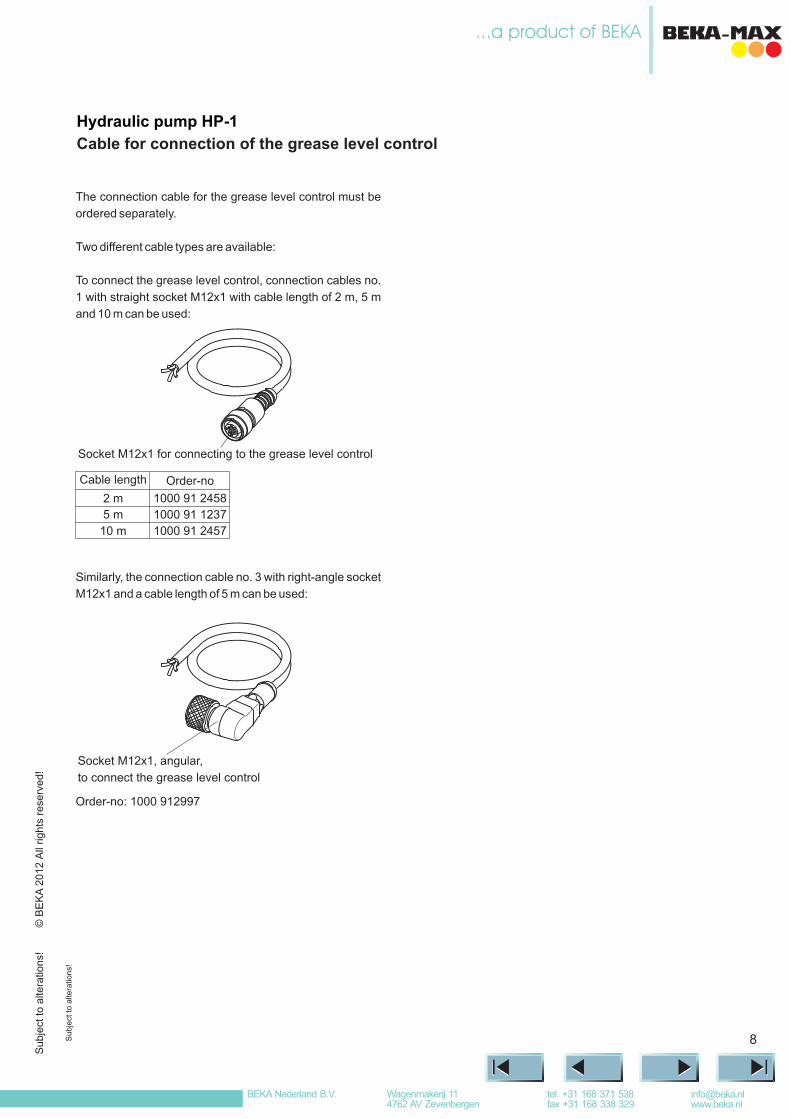
The connection cable for the grease level control must be
ordered separately.
Two different cable types are available:
To connect the grease level control, connection cables no.
1 with straight socket M12x1 with cable length of 2 m, 5 m
and 10 m can be used:
Similarly, the connection cable no. 3 with right-angle socket
M12x1 and a cable length of 5 m can be used:
Order-no: 1000 912997
Hydraulic pump HP-1
Cable for connection of the grease level control
8Su
bje
ct to a
ltera
tions!
Socket M12x1 for connecting to the grease level control
Cable length
2 m
5 m
10 m
Order-no
1000 91 2458
1000 91 1237
1000 91 2457
Socket M12x1, angular,
to connect the grease level control
© B
EK
A2012 A
ll rights
rese
rved!
Subje
ct to a
ltera
tions!
BEKA Nederland B.V. [email protected]
tel. +31 168 371 538fax +31 168 338 329
Wagenmakerij 114762 AV Zevenbergen
9
Hydraulic pump HP-1
Order key of the pump
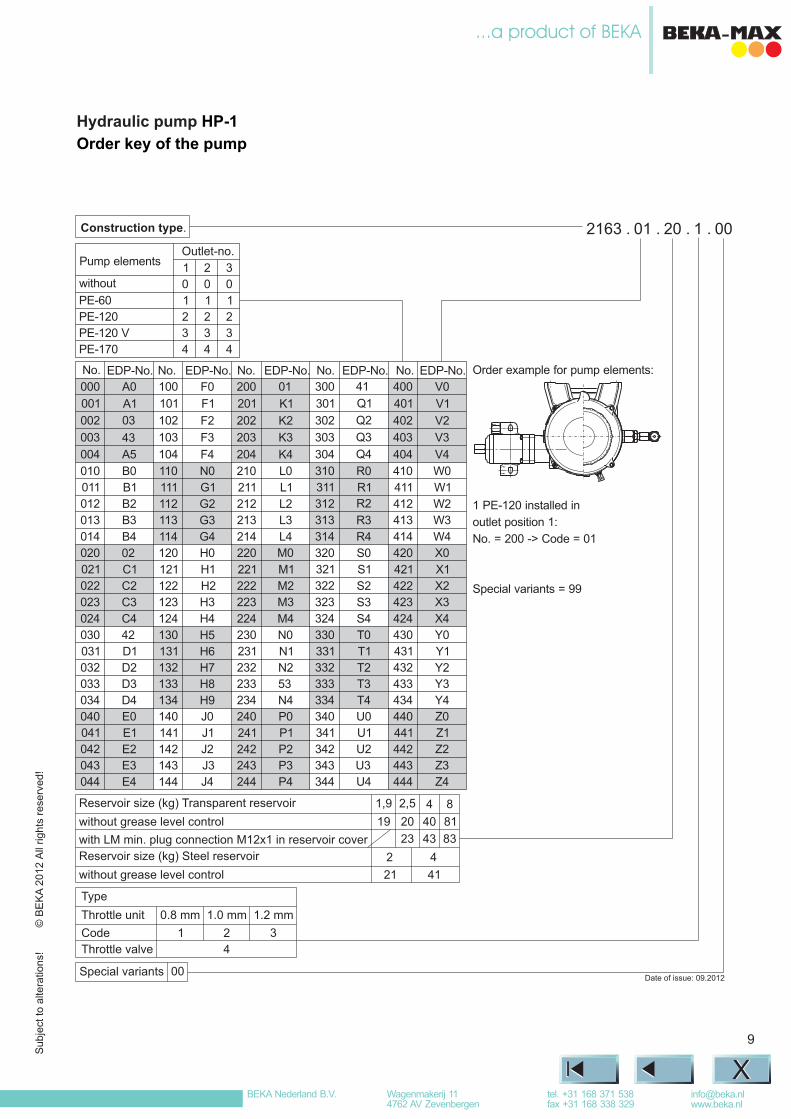
2163 . 01 . 20 . 1 . 00
1 2 3
0 0 0
PE-60 1 1 1
PE-120 2 2 2
PE-120 V 3 3 3
PE-170 4 4 4
000
001
002
003
004
010
011
012
013
014
020
021
022
023
024
030
031
032
033
034
040
041
042
043
044
A0
A1
03
43
A5
B0
B1
B2
B3
B4
02
C1
C2
C3
C4
42
D1
D2
D3
D4
E0
E1
E2
E3
E4
100
101
102
103
104
110
111
112
113
114
120
121
122
123
124
130
131
132
133
134
140
141
142
143
144
F0
F1
F2
F3
F4
N0
G1
G2
G3
G4
H0
H1
H2
H3
H4
H5
H6
H7
H8
H9
J0
J1
J2
J3
J4
200
201
202
203
204
210
211
212
213
214
220
221
222
223
224
230
231
232
233
234
240
241
242
243
244
01
K1
K2
K3
K4
L0
L1
L2
L3
L4
M0
M1
M2
M3
M4
N0
N1
N2
53
N4
P0
P1
P2
P3
P4
300
301
302
303
304
310
311
312
313
314
320
321
322
323
324
330
331
332
333
334
340
341
342
343
344
41
Q1
Q2
Q3
Q4
R0
R1
R2
R3
R4
S0
S1
S2
S3
S4
T0
T1
T2
T3
T4
U0
U1
U2
U3
U4
400
401
402
403
404
410
411
412
413
414
420
421
422
423
424
430
431
432
433
434
440
441
442
443
444
V0
V1
V2
V3
V4
W0
W1
W2
W3
W4
X0
X1
X2
X3
X4
Y0
Y1
Y2
Y3
Y4
Z0
Z1
Z2
Z3
Z4
Construction type.
Outlet-no.
EDP-No. EDP-No. EDP-No. EDP-No. EDP-No.No. No. No. No. No.
Pump elements
without
0.8 mm
1
1.2 mm
3
1.0 mm
2
4
Type
Throttle unit
Code
Throttle valve
Special variants 00
Order example for pump elements:
1 PE-120 installed in
outlet position 1:
No. = 200 -> Code = 01
Special variants = 99
2
21
4
41
1,9
19
Reservoir size (kg) Steel reservoir
without grease level control
Reservoir size (kg) Transparent reservoir
without grease level control
with LM min. plug connection M12x1 in reservoir cover
2,5
20
23
4
40
43
8
81
83
Date of issue: 09.2012
XX
© B
EK
A2012 A
ll rights
rese
rved!
Subje
ct to a
ltera
tions!
BEKA Nederland B.V. [email protected]
tel. +31 168 371 538fax +31 168 338 329
Wagenmakerij 114762 AV Zevenbergen