Embed Size (px)
Citation preview
HYDRAULIC MODEL STUDIES - AERATION OF THE SUBMERGED
JET-FLOW GATES AT SEMINOE DA
February 1990
U.S. DEPARTMENT OF THE INTERIOR Bureau of Reclamation
Denver Off ice Research and Laboratory Services Division
Hydraulics Branch

Bureau b i ~ i c l a m a t i o n TECHNICAL REPORT STANDARD TITLE PAGl
HYDRAULIC MODEL STUDIES - AERATION OF THE SUBMERGED JET-FLOW GATES AT SEMINOE DAM
I 7. AUTHOR^) 8. P E R F O R M I N G O R G A N I Z A T I O N
R E P O R T NO.
K. Warren Frizell
9. P E R F O R M I N G O R G A N I Z A T I O N N A M E A N D ADDRESS
14. SPONSORING A G E N C Y C O D E
R-90-01 10. WORK U N I T NO.
Bureau of Reclamation Denver Office Denver CO 80225
12. SPONSORING A G E N C Y N A M E A N D ADDRESS
1 DlBR 15. S U P P L E M E N T A R Y N O T E S
11. C O N T R A C T OR G R A N T NO.
13. T Y P E O F R E P O R T A N D P E R I O D C O V E R E D
I Microfiche and hard copy available at the Denver Office, Denver, Colorado.
16. A B S T R A C T
A study was performed to evaluate placement of an aeration vent on a submerged jet-flow gate at Seminoe Dam. Size restrictions on the discharge tube downstream from the gate suggested aeration as a means to protect the downstream areas from cavitation damage. Four air vent locations were tested. The vent on the top centerline of the discharge tube just downstream of the gate frame performed the best. Ratios of QJQ, greater than 10 percent were measured throughout the entire range of gate openings. A minimum vent size of 16 inches in diameter is needed to keep air velocities through the vent below 200 ft/s; however, the use of existing 18-inch-diameter piping
17. K E Y WORDS A N D D O C U M E N T A N A L Y S l S
D E S C R I P T O R S - - hydraulic model study/ jet-flow gate/ submergence/ aeration/ cavitation/
Seminoe Dam/ Wyoming/
I c . C O S A T I F i e l d / G r o u p COWRR: SRIM:
21. NO. O F PAGE
8 2 2 . P R I C E
18. D I S T R I B U T I O N S T A T E M E N T 19. S E C U R I T Y C L A S S (THIS REPORT)
U N C L A S S I F I E D 20. S E C U R I T Y C L A S S
(THIS PAGE)
U N C L A S S I F I E D

R-90-01
HYDRAULIC MODEL STUDIES -AERATION OF THE SUBMERGED
JET-FLOW GATES AT SEMINOE DAM
by
K. Warren Frizell
Hydraulics BranchResearch and Laboratory Services Division
Denver OfficeDenver, Colorado
February 1990
UNITED STATES DEPARTMENT OF THE INTERIOR * BUREAU OF RECLAMATION

ACKNOWLEDGMENTS
This study was the result of a request by the SDCW (Sangre deCristo Water Company), Santa Fe, New Mexico. The specialassistance throughout the project by Phillip Soice of the SDCWand Peter Kraai of Scanlon and Associates, Sante Fe, New Mexico,was appreciated.
Mission: As the Nation's principal conservation agency, theDepartment of the Interior has responsibility for most of ournationally owned public lands and natural and culturalresources. This includes fostering wise use of our land andwater resources, protecting our fish and wildlife, preservingthe environmental and cultural values of our national parksand historical places, and providing for the enjoyment of lifethrough outdoor recreation. The Department assesses ourenergy and mineral resources and works to assure that theirdevelopment is in the best interests of all our people. TheDepartment also promotes the goals of the Take Pride inAmerica campaign by encouraging stewardship and citizenresponsibility for the public lands and promoting citizenparticipation in their care. The Department also has a majorresponsibility for American Indian reservation communitiesand for people who live in Island Territories underU.S. Administration.
The information contained in this report regarding commercialproducts or firms may not be used for advertising or promotionalpurposes and is not to be construed as an endorsement of anyproduct or firm by the Bureau of Reclamation.
11

CONTENTS
Purpose. . . . . . . . . . . . . . . . . . . . . . . . . . . . . . . . . . . . . . . . . . . . . . . . . . . . . . . . . .
Introduction. . . . . . . . . . . . . . . . . . . . . . . . . . . . . . . . . . . . . . . . . . . . . . . . . . . . . . .
The model. . . . . . . . . . . . . . . . . . . . . . . . . . . . . . . . . . . . . . . . . . . . . . . . . . . . . . . .
The tests. . . . . . . . . . . . . . . . . . . . . . . . . . . . . . . . . . . . . . . . . . . . . . . . . . . . . . . . .
Test results. . . . . . . . . . . . . . . . . . . . . . . . . . . . . . . . . . . . . . . . . . . . . . . . . . . . . . .
Conclusions and recommendations. . . . . . . . . . . . . . . . . . . . . . . . . . . . . . . . . . . . . .
Bibliography. . . . . . . . . . . . . . . . . . . . . . . . . . . . . . . . . . . . . . . . . . . . . . . . . . . . . . .
Figure
FIGURES
123
1:21 scale hydraulic model of one Seminoe jet-flow gate. . . . . . . . . . . . . .Air vent locations tested. . . . . . . . . . . . . . . . . . . . . . . . . . . . . . . . . . . . .Coefficient of discharge for 60-inch jet-flow gate,
aerated versus nonaerated ..................................Piezometric pressure on discharge tube invert,
no aeration. . . . . . . . . . . . . . . . . . . . . . . . . . . . . . . . . . . . . . . . . . . . . .Piezometric pressures in discharge tube invert,
top vent open. . . . . . . . . . . . . . . . . . . . . . . . . . . . . . . . . . . . . . . . . . . .Air demand curves, four vent configurations. . . . . . . . . . . . . . . . . . . . . .Aeration from top vent. . . . . . . . . . . . . . . . . . . . . . . . . . . . . . . . . . . . . .
4
5
67
111
Page
1
1
1
2
2
3
3
55
6
6
778


PURPOSE
Two 60-inch jet-flow gates are being installed as replacements to the needle valves in the outletworks at Seminoe Dam, Wyoming. Submerged operation of these gates using the existing dischargetubes will result in cavitation damage downstream from the gate. Aeration downstream from thegate is the only viable option without replacement of the discharge tubes with expanded conduitsections. A hydraulic scale model (1:21) was used to evaluate aeration downstream from the jet-flow gate. Discharge characteristics, pressures in the discharge tubes, and air demand weremeasured for four different vent configurations.
INTRODUCTION
Submerged operation of a jet-flow gate requires protective measures in the area downstream of thegate. An expanded conduit section downstream from the gate is normally used to ensure that thecavitation cloud occurring in the shear layer does not collapse on the discharge tube walls. The sizeof the recommended expansion is 3D, where D is the diameter of the jet-flow gate (Isbester, 1975).This expansion allows good circulation around the jet, protecting the downstream surfaces fromcavitation damage (Isbester, 1974; and Burgi and Fujimoto, 1973). The diameter of the expansioncan be reduced somewhat if the length of the discharge tube is kept very short (Mefford, 1987).Protection of the discharge tube from cavitation by using aeration is necessary when conduitexpansions downstream from the gate are not possible.
Replacement of the needle valves at Seminoe Dam with two 60-inch jet-flow gates is underway.New tailwater studies project that these jet-flow gates may operate with up to 2.5 feet of waterabove the centerline of the gates. The existing discharge tubes provide only a lAD expansion.Without aeration of the jet, the discharge tubes will be subject to cavitation damage. Aeration ofthe discharge tubes by providing an air vent downstream from the gate was studied in a hydraulicmodel. Four different locations for the vent were tested. Recommendations for vent size andlocation are given.
THE MODEL
The studies were made using a 1:21 scale hydraulic model. The model included one jet-flow gatewith existing piping upstream and downstream of the gate (fig. 1). The model was placed in thelaboratory's low ambient pressure chamber for ease of operation and to observe the location ofcavitation clouds in the model. The ambient pressure in this 600-fe chamber can be reduced to 0.1atmosphere and can deliver up to 10 fe /s through an installed model. Model scaling was based onequal Froude numbers in the model and prototype:
(y2/ gL)m = (y2/ gL)p (1)
where:
vgLm,p
= velocity= gravitationalconstant= characteristiclength= model and prototype

Tests were conducted to compare four different air vent locations. Measurements taken includedupstream head, discharge, gate opening, air velocity into the vent piping, and piezometric pressuresat four locations on the invert of the discharge tube downstream from the gate. All tests were runwith the maximum tailwater condition (elevation 6147.5 feet). Documentation also included stillphotographs and video.
THE TESTS
Four different air vent locations were studied (fig. 2). The test procedure was as follows:
1. Set ga te opening.2. Set tailwater elevation.3. Adjust flow rate to achieve desired reservoir head upstream of the gate.4. Record discharge and piezometric pressures.5. Measure air velocity into air vent piping.
This procedure was repeated for the full range of gate openings from 5 to 100 percent.
TEST RESULTS
The test results are presented as follows: discharge characteristics (fig. 3), piezometric pressuresdownstream from the gate (figs. 4-5), and air demand curves (fig. 6).
Discharge characteristics of the jet-flow gate varied with aeration and the location of the air vent.The discharge coefficient Cd is defined as:
Cd =Q
Aup[2g(Hup - Hdn)f'(2)
where:
gHup
Hdn
= Discharge (fejs)= Area of upstream pipe (fe)= Gravitational constant (ftjs2)= Pressure head upstream from the gate (ft)= Pressure head downstream from the gate (ft)
QAup
Without aeration, the discharge coefficient reaches a value of 0.88 when the gate is fully open. Thisvalue drops to 0.62 when the discharge tube is aerated with the top or 45° vent configurations andto only 0.41 for the bottom vent configuration (fig. 3).
The piezometric pressures on the discharge tube invert also vary with aeration. Without aeration,impact of the jet remains close to the gate for openings up to 30 percent (fig. 4). Above 40 percentopen, negative pressures are produced just downstream of the gate. The jet impact point movesdown the conduit to the second and third piezometer locations. When aerated from the top vent,the jet impact is near the first piezometer tap for the 5-percent opening and begins moving
2
downstream as the gate is opened. At 100 percent open, the jet spnngs free over all fourpiezometer taps (fig. 5).
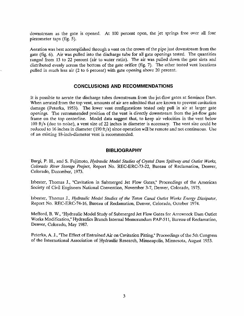
Aeration was best accomplished through a vent on the crown of the pipe just downstream from thegate (fig. 6). Air was pulled into the discharge tube for all gate openings tested. The quantitiesranged from 13 to 22 percent (air to water ratio). The air was pulled down the gate slots anddistributed evenly across the bottom of the gate orifice (fig. 7). The other tested vent locationspulled in much less air (2 to 6 percent) with gate opening above 20 percent.
CONCLUSIONS AND RECOMMENDATIONS
It is possible to aerate the discharge tubes downstream from the jet-flow gates at Seminoe Dam.When aerated from the top vent, amounts of air are admitted that are known to prevent cavitationdamage (Peterka, 1953). The lower vent configurations tested only pull in air at larger gateopenings. The recommended position of the vent is directly downstream from the jet-flow gateframe on the top centerline. Model data suggest that, to keep air velocities in the vent below100 ftls (due to noise), a vent size of 22 inches in diameter is necessary. The vent size could bereduced to 16 inches in diameter (190 ft/s) since operation will be remote and not continuous. Useof an existing 18-inch-diameter vent is recommended.
BIBLIOGRAPHY
Burgi, P. R., and S. Fujimoto, Hydraulic Model Studies of Crystal Dam Spillway and Outlet Works,Colorado River Storage Project, Report No. REC-ERC-73-22, Bureau of Reclamation, Denver,Colorado, December, 1973.
Isbester, Thomas J., "Cavitation in Submerged Jet Flow Gates," Proceedings of the AmericanSociety of Civil Engineers National Convention, November 3-7, Denver, Colorado, 1975.
Isbester, Thomas J., Hydraulic Model Studies of the Teton Canal Outlet Works Energy Dissipator,Report No. REC-ERC-74-16, Bureau of Reclamation, Denver, Colorado, October 1974.
Mefford, B. W., "Hydraulic Model Study of Submerged Jet Flow Gates for Arrowrock Dam OutletWorks Modification," Hydraulics Branch Internal Memorandum PAP-5U, Bureau of Reclamation,Denver, Colorado, May 1987.
Peterka, A. J., "The Effect of Entrained Air on Cavitation Pitting," Proceedings of the 5th Congressof the International Association of Hydraulic Research, Minneapolis, Minnesota, August 1953.
3

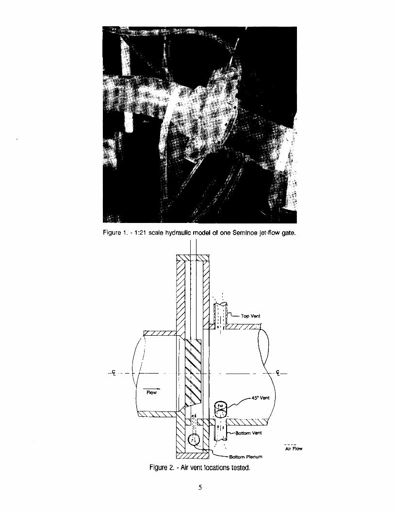
Figure 1. - 1:21 scale hydraulic model of one Seminoe jet-flow gate.
-t(-
Flow
Air Flow
Figure 2. - Air vent locations tested.
5

~15.00HQ)..j-JcD
~10.00'+-;0
..j-J'+-;'---" 5.00
i:L)
~~IJ10.00
IJ1i:L)
~P.,
-5.00
~ 0.9000:::<r: 0.80;:r:::
U(f) 0.70>-<~
~0.60
0
b0.50
Z:::J OAOU>-<
~ 0.30
~80.20
0.10
0.00
100I I I I I I I I I I
I I I I I I I I I I__L__L__L__L__L__L__L__L__L__'I I I I I I I I I
I I I I I I I I I I__L__L__L-_L__L__L__L__L_-L- I
I I I I I I I I I II I \ I I 1 I ! I I
__L__L__L__L-_L-_L__L__L__L__I
I I I I I I I I I II I I I I I I I__L-_L__L__L__L__L__L__L-
L-I I I I I I I I II I I I I I I I I
__L__L__L__L_-L-_L__L__L-I I I I I I I II I I I I I I
__L__L__L__L__L-_L__L-
I I I I I I I I LEGEND:I I I I I I I I
- -L
- -L
- -L
- -L - - L - - -
L- -
L- -
L- -
I 008EiE) NO AERATIONI I I I I I I I I G888EJ TOP VENTI I I I I I I I I ~ BOTTOM VENT
- -L
- -L
- -L
- -L
- - -L - - L
- -L
- -L - - I ~ 45-DEGREE OFFI I I I I I I I I
I I I I I I I I__L_- __L__L__L__L__L__L__II I I I I I I I I
I I I I I I I I
I I I I I I I I I I I I I I I I10 20 30 40 50 60 70 80 90 100
GATE OPENING (PERCENT)
-------------------------
0
BOTTOM
Figure 3. - Coefficient of discharge for 50-inch jet-flow gate, aerated versus nonaerated.
-10.00
20.00 -----------------------------I I II I II I II I IL L I
IIII
-L______-I II II I II I I
L L II I II I II I II I I
I2 3
PIEZOMETER NUMBER
LEGEND:
GeeeE) 5-PERCENTG8BBf] lO-PERCENT
I ~ l5-PERCENT~ 20-PERCENT~ 30- PERCENT-- 40-PERCENT~ 50- PERCENT
50-PERCENT~ 80- PERCENT
I4
Figure 4. - Piezometric pressure on discharge tube invert, no aeration.
6

~~10.00
~lf1lf1 5.00
~~(l.0.00
40.00
35.00
~
~ 30.00+-J(\j
~ 25.00
<H0 20.00
+-J<H'--" 15.00
-5.00
-10.00
"Q),oj
'"G'" 0.10
".~G'
-----------------------------I 1 I1 I IL L_____----I I I
11
II
- - 11
LEGEND:
GeeeE) 5- PERCENTGBBBEJ10-PERCENT~ 15-PERCENT<t%OO 20- PERCENT
I -- 30- PERCENT~ 40- PERCENT
- 50- PERCENTI ~ 60- PERCENTI ~ 80- PERCENT
- - - - - - - - I***** 100-PERCENTI
--------- L II II I
2 3PIEZOMETER NUMBER
4
Figure 5. - Piezometric pressures in discharge tube invert, top vent open.
0.25 -----------------------------
Ge89E) TOP VENTG88E3f] BOTTOM VENT~ 45-DEG. VENT
--- BOTTOMPLENUM
0.20
0.15
0.05
0.000 20 30 40 50 60 70 80 90
GATE OPENING (percent)10010
Figure 6. - Air demand curves, four vent configurations.
7

Figure 7. - Aeration from top vent; water mixture flowing along bottom of discharge tube.
8

Mission of the Bureau of Reclamation
The Bureau of Reclamation of the U.S. Department of the Interior is responsible for the development and conservation of the Nation's water resources in the Western United States.
The Bureau's original purpose "to provide for the reclamation of arid and semiarid lands in the West" today covers a wide range of interrelated functions. These include providing municipal and industrial watersupplies; hydroelectric power generation; irrigation water for agriculture; water quality improvement; flood control; river navigation; river regulation and control; fish and wildlife enhancement; outdoor recreation; and research on water-related design, construction, materials, atmospheric management, and wind and solar power.
Bureau programs most frequently are the result of close cooperation with the U.S. Congress, other Federal agencies, States, local governments, academic institutions, water-user organizations, and other concerned groups.
A free pamphlet is available from the Bureau entitled "Publications for Sale." It describes some of the technical publications currently available, their cost, and how to order them. The pamphlet can be obtained upon request from the Bureau of Reclamation, Attn D-7923A, PO Box 25007, Denver Federal Center, Denver CO 80225-0007.