Embed Size (px)
Citation preview

Interface Devices, Inc. Hydraulic Mini Mule
INSTALLATION, OPERATION & MAINTENANCE MANUAL
IMPORTANT! FILE THIS MANUAL IN A SAFE PLACE FOR FUTURE SERVICE & PARTS NEEDS
ALWAYS REFERENCE THE SERIAL NUMBER FOR SERVICE & PARTS REQUESTS
Safety instructions specifically pertaining to this unit appear throughout this manual highlighted by these signal words ** Warning** and **Caution ** to denote different levels of hazard. Warning: denotes practices, which if not carefully followed, could result in property damage, SERIOUS personal injury and /or DEATH Caution: denotes practices which if not carefully followed, could result in minor personal injury or damage to equipment.
Hydraulic Mini Mule Serial Number:___________________
STATEMENT OF WARRANTY Interface Devices, Inc. (IDI) warrants it’s products to be free from defects in material and workmanship under normal use and service for a period of one (1) year from date of shipment. Any defect discovered after the warranty period has expired will be deemed to be outside the above coverage. No goods claimed to be under warranty shall be accepted for return unless authorized by IDI. Upon discovery of a defect (other than freight damage) or a shortage of an item received in the original shipping container, the purchaser shall, within (10) calendar days, deliver notice of the defect or shortage. Damaged freight claims must be placed with the freight carrier and will not be honored by IDI. If after due investigation of a claim of defect or shortage is found valid, IDI, at it’s sole discretion, may discharge it’s entire obligations to the purchaser by either repair or replacement of the defective product or component and for shortages by furnishing a replacement of the missing quantity. This express warrantee supersedes and is in lieu of all other remedies and warranties,
including the implied warranties of merchantability and fitness for a particular purpose,
and liability for negligence. IN NO EVENT SHALL IDI BE LIABLE FOR INCIDENTAL OR
CONSEQUENTIAL LOSSES, EXPENSES OR DAMAGES INCLUDING DAMAGES FOR
PERSONAL INJURY OR COMMERCIAL LOSS.
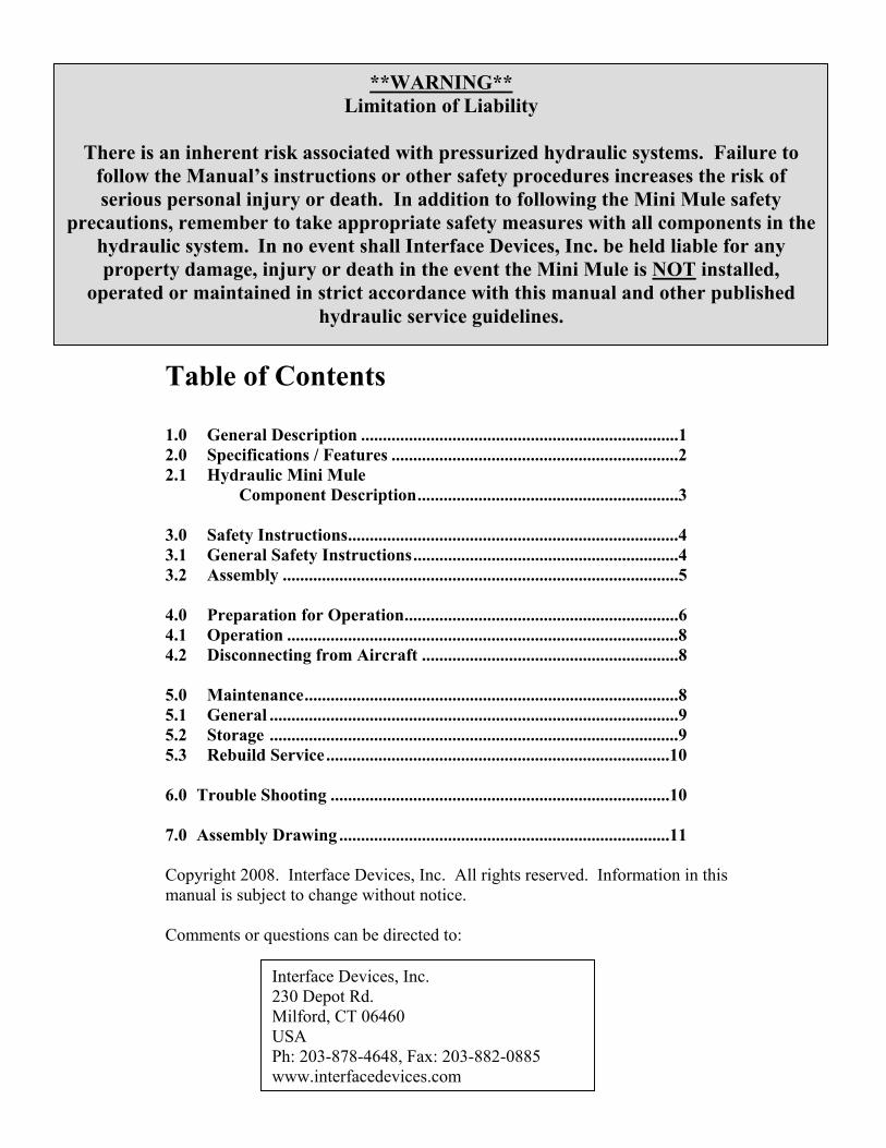
**WARNING** Limitation of Liability
There is an inherent risk associated with pressurized hydraulic systems. Failure to
follow the Manual’s instructions or other safety procedures increases the risk of serious personal injury or death. In addition to following the Mini Mule safety
precautions, remember to take appropriate safety measures with all components in the hydraulic system. In no event shall Interface Devices, Inc. be held liable for any property damage, injury or death in the event the Mini Mule is NOT installed,
operated or maintained in strict accordance with this manual and other published hydraulic service guidelines.
Table of Contents 1.0 General Description .........................................................................1 2.0 Specifications / Features ..................................................................2 2.1 Hydraulic Mini Mule Component Description............................................................3 3.0 Safety Instructions............................................................................4 3.1 General Safety Instructions.............................................................4 3.2 Assembly ...........................................................................................5 4.0 Preparation for Operation...............................................................6 4.1 Operation ..........................................................................................8 4.2 Disconnecting from Aircraft ...........................................................8 5.0 Maintenance......................................................................................8 5.1 General ..............................................................................................9 5.2 Storage ..............................................................................................9 5.3 Rebuild Service...............................................................................10 6.0 Trouble Shooting ..............................................................................10
7.0 Assembly Drawing ............................................................................11 Copyright 2008. Interface Devices, Inc. All rights reserved. Information in this manual is subject to change without notice. Comments or questions can be directed to:
Interface Devices, Inc. 230 Depot Rd. Milford, CT 06460 USA Ph: 203-878-4648, Fax: 203-882-0885www.interfacedevices.com

I N T E R F A C E D E V I C E S , I N C . - H Y D R A U L I C M I N I - M U L E -
1.0 General Description
Features:
• No inlet air valve, air regulator or air lubricator required. • Integrated circuit design. No external tubing or fittings. • Maintains a constant pressure output with minimal air consumption. • Polymeric seals and bearings for long life and high efficiency. • Totally sparkless operation. • Simple on/off air toggle pressurizes and depressurizes system. • Compressed air input for operation or can be nitrogen powered for remote operation. • 30: 1 Pump ratio delivers 2,400-3750 psi hydraulic pressure with 80-125 psi inlet air
pressure. • No internal heat build-up • Pre-tested with the specified hydraulic fluid. • Operates using aircraft hydraulic system reservoir. Can be adapted to utilize an
external reservoir. • Adaptable for multiple applications by varying output fitting configurations.
** Caution ** ALWAYS WEAR PROTECTIVE EQUIPMENT WHEN INSTALLING, OPERATING OR MAINTAINING THE MINI MULE INCLUDING BUT NOT LIMITED TO SAFETY GLASSES, PROTECTIVE GLOVES, SHOES AND CLOTHING. FOLLOW ALL GUIDELINES ESTABLISHED IN THIS MANUAL AND THE MANUALS OF ALL OTHER EQUIPMENT USED IN CONJUNCTION WITH THE MULE INCLUDING THE AIRCRAFT MAINTENANCE MANUAL
1

I N T E R F A C E D E V I C E S , I N C . - H Y D R A U L I C M I N I - M U L E -
2.0 Specifications & Features:
Figure 1:
2

I N T E R F A C E D E V I C E S , I N C . - H Y D R A U L I C M I N I - M U L E -
Item 1: Air Regulator
Item 2: Inlet Pressure Gauge
Item 3: Pump “ON/OFF” Switch (air operated)
Item 4: Dump Valve
Item 5: Output Pressure Gauge
Item 6: Pressure Reducing Valve
Item 7: Accumulator (Installations may vary)
Item 8: Mounting hole locations (4 each)
Item 9: Pump Pressure gauge
• “P” Pressure Port – ½ NPT
• Air Inlet – ½ NPT
• “T” Return Port – ½ NPT
2.1 Component Description (Refer to Fig. 1. for component location.)
2.1.1 Air Regulator. Regulates the inlet supply pressure, as read on the inlet pressure gauge.
Rotate the knob clockwise (IN) for higher output pressure. Rotate it counterclockwise (OUT) for lower pressures. Push the collar down to lock the Air Regulator.
** Caution ** *DO NOT EXCEED 125 PSI INLET PRESSURE*
2.1.2 Inlet Pressure Gauge. Reads the regulated shop supply pressure. 2.1.3 “ON/OFF” Toggle Switch. Provides the ability to turn the pump ON/OFF simultaneously actuating the Dump Valve CLOSED/OPEN 2.1.4 Dump Valve. Dumps system pressure when the pump is shut off. 2.1.5 Output Pressure Gauge. Indicates outlet pressure level as set by the Pressure Reducing
Valve. 2.1.6 Pressure Reducing Valve. Controls the output pressure. Operator adjustable from 1000 to
3000 psi. Rotate the valve clockwise (IN) for higher output pressure. Rotate it counter-clockwise (OUT) for lower pressures. Lock the position of the valve by tightening the collar.
2.1.7 Accumulator. The accumulator pressure is typically precharged to 80% of the minimum system pressure. Allows for damping of pressure pulsations.
2.1.8 Mounting holes. Used for mounting the pump with ¼-20 fasteners. 2.1.9 Pump Pressure Gauge. Indicates the internal pump pressure as dictated by the regulated air
pressure. Note this pressure is always higher than the Output pressure downstream of the Pressure Reducing Valve.
2.1.10 “P” Pressure Port. System outlet port for the pressurized fluid. Pressure outlet at this port is indicated on the Output Pressure Gauge. This ½ NPT port is to be connected to the hydraulic supply of the aircraft with customer supplied hoses and fittings.
3

I N T E R F A C E D E V I C E S , I N C . - H Y D R A U L I C M I N I - M U L E -
2.1.11 “T” Return Port. System fluid port. To be used to deliver fluid from the aircraft fluid reservoir to the Mini Mule. This ½ NPT port is to be connected to the hydraulic reservoir of the aircraft with customer supplied hoses and fittings.
2.1.12 Air Inlet. Inlet supply pressure port. This ½ NPT port is to be connected to the compressed air supply with customer supplied hoses and fittings.**DO NOT EXCEED 125 PSI**
Application: Designed for use by maintenance technicians for pressurizing and testing aircraft hydraulic systems and components. Pay special attention to fluid requirements as hydraulic fluids are not all compatible.
** Caution ** It is mandatory that this instruction manual be read, understoodand followed by all persons operating this high- pressurehydraulic Mule.
3.0 Safety Instructions
3.0.1 General: Information presented in this manual and on various labels, tags and plates on the unit pertain to equipment design, installation, operation, maintenance and trouble shooting which should be read, understood and followed for safe and effective use of this equipment.
3.0.2 Safety: The operation, maintenance, and trouble shooting of this high pressure hydraulic Mini Mule requires practices and procedures that ensure personal operator safety and the safety of others. Therefore, this equipment is to be operated and maintained only by qualified persons in accordance with this manual and all applicable local codes.
3.0.3 Training: Read through this entire manual prior to operation of this hydraulic Mule. All personnel using this Mule should understand and follow this manual and be properly trained. Contact Interface Devices for any specific questions about the installation, operation or maintenance of the Mini Mule.
3.1 General Safety Precautions
3.1.1 Pressures: Fluids under pressure are a potential hazard in the form of stored energy. Accidents can occur when this energy is improperly handled. Be sure that all equipment used is compatible and designed to control the pressures encountered.
4

I N T E R F A C E D E V I C E S , I N C . - H Y D R A U L I C M I N I - M U L E -
3.1.2 Hydraulic Fluid: Hydraulic Fluids can be hazardous to personal health and are potentially flammable. Take specific precautions for hydraulic fluid interaction, ie., gloves, safety glasses or face shield, etc. Do not use or store this Mule near open heat sources. Read and understand precautions in fluid Material Safety Data Sheet (MSDS) provided by the fluid supplier.
** Warning ** High pressure hydraulic fluid leaks can be hazardous. It is not recommended to check for leaks with your bare hands. Be especially cautious of misting fluid leaks as they can cause shortness of breath, difficulty breathing, or respiratory damage.
It is important to understand the dangers of operating around high pressure hydraulic systems.
3.2 Assembly:
3.2.1 Although the Hydraulic Mini Mule is inspected prior to shipping, it could potentially be damaged during shipping. Therefore, it should be carefully unpacked and placed on a clean level surface for inspection. Please notify the shipping company of any damages as soon as possible.
3.2.2 The Mini Mule is equipped with two (2) angle brackets with four (4) mounting holes for mounting
with ¼-20 fasteners. Alternatively, the bottom of the Mule is furnished with three ¼-20 by ½” deep tapped holes for mounting to a bracket or cart.
3.2.3 Customer installed parts (Keep hydraulic components clean and contaminant free):
a. High-pressure hose and fittings rated to a minimum of 4000 psi to connect to aircraft hydraulic supply. b. Low-pressure return hose and fittings to connect to aircraft hydraulic reservoir c. Air supply hose and fittings with shut-off valve rated for 125 psi minimum d. 40 Micron inlet air filter rated to 125 psi at 40 SCFM
Dissimilar quick disconnect fittings are recommended for the two hydraulic hose assembly to ensure the Return line cannot be connected accidentally to the High Pressure line. Clearly label each hose according with pressure rating. COMPRESSED AIR COMPONENTS 3.2.4 A minimum supply hose inside diameter of ½ inch (12.7 mm) rated for a minimum of 125 psi.
Hose assembly should have a ½ inch in-line shut-off valve.
3.2.5 Back the Air Regulator (CCW) all the way out.
5

I N T E R F A C E D E V I C E S , I N C . - H Y D R A U L I C M I N I - M U L E -
3.2.6 Install a ½ inch, 40 micron minimum air filter as close as possible to the pump inlet with a ½ NPT pipe nipple.
3.2.7 With the shut-off valve in the “off” position, install the hose to the filter. Note: Do not install a lubricator or external regulator. CONNECTION TO MULE 3.2.7 Remove protective caps from “T” and “P” fittings.
3.2.8 Connect the hoses to the “T” (return) and “P” (pressure) ports. Tighten securely.
3.2.9 Install protective plugs in the free end of the hoses
Check all components for integrity. Carefully inspect all gauges, fittings, and connections for damage or leaks.
Always inspect unit before usshould never be used.
4.0 Preparation for Operatio
ACCUMULATOR NITROGEN PRE
Do not exceed 2500 PSI accrequires a higher accumulatoinformation.
A dry nitrogen cylinder with a minimumhose, gauge and charge valve assembly a 4.1.0 Remove the cap from the accumu 4.1.1 Open the accumulator’s inlet val 4.0.4 SLOWLY open the valve on the
accumulator.
** Warning ** e. Damaged or contaminated or equipment
n
CHARGE PROCEDURE:
u
v
n
** Warning ** mulator precharge. If the hydraulic system r precharge, contact Interface Devices for more
of 3000 psi nitrogen available and an accumulator charge re required
lator’s gas valve and connect the charge valve’s adapter to it.
e.
itrogen cylinder to allow nitrogen to flow into the
6

I N T E R F A C E D E V I C E S , I N C . - H Y D R A U L I C M I N I - M U L E -
4.0.5 Charge the accumulator to 80% of minimum operating pressure. When the required pressure is indicated on the charge gauge, close the cylinder gas valve.
4.0.6 Close the accumulator inlet valve. 4.0.7 SLOWLY loosen the charge valve assembly from the accumulator gas valve to allow trapped
nitrogen to escape. Remove the assembly and install the gas valve cap to the accumulator inlet valve.
INITIAL START-UP, BLEEDING & PRESSURE SETTINGS: 4.0.8 Back-out the air regulator knob.
4.0.9 Turn-in the knurled knob of the pressure reducer valve (labeled "PR") 3 turns.
4.0.10 Remove both fittings from the aircraft end of the pressure and return hoses. 4.0.11 Connect the return hose from port “T” to the aircraft and tighten. 4.0.12 Connect the pressure hose from port “P” to the aircraft and leave it slightly loose for bleeding
purpose. 4.0.13 Make sure the pump on/off air toggle switch is in the "off" position (toggle toward the air
regulator). 4.0.14 Connect and turn on the air supply to the pump. 4.0.15 Switch the pump toggle switch to the "on" position (Toggle towards the hydraulic hose end of
the pump).
** Warning ** Be careful of the fluid escaping the pressure line during the bleeding procedure. This fluid may be under pressure and can be emitted as a mist. Take the necessary precautions when torquing the pressure fitting after the air has escaped.
4.0.16 Slowly turn in the air regulator (CW) until the pump cycles slowly. Allow fluid to bleed
through the loose pressure fitting until an air-free stream of oil is observed. Turn the toggle switch off and tighten the pressure fitting
4.0.17 Turn the toggle switch on and adjust the air regulator until 2500 PSI in noted on the Pump
Pressure Gauge (the pump will make several cycles to fill the Accumulator and then stop. The air pressure gauge will indicate approximately 85 PSI).
7
I N T E R F A C E D E V I C E S , I N C . - H Y D R A U L I C M I N I - M U L E -
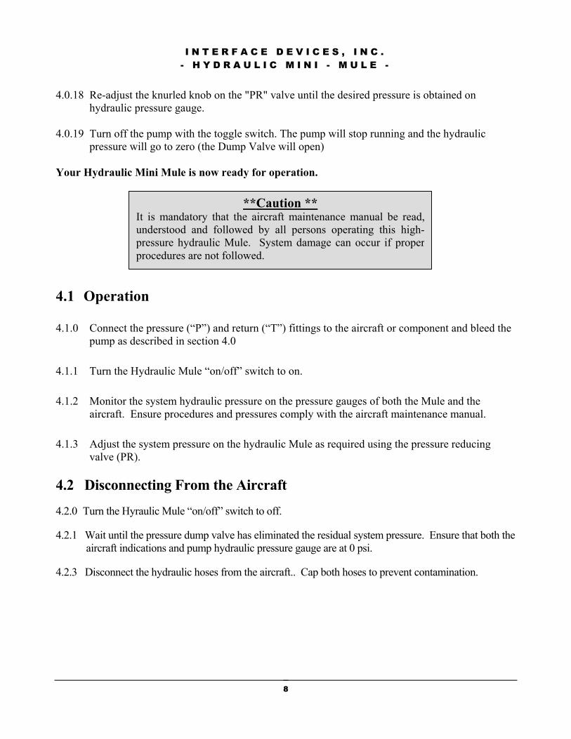
4.0.18 Re-adjust the knurled knob on the "PR" valve until the desired pressure is obtained on
hydraulic pressure gauge. 4.0.19 Turn off the pump with the toggle switch. The pump will stop running and the hydraulic
pressure will go to zero (the Dump Valve will open) Your Hydraulic Mini Mule is now ready for operation.
**Caution ** It is mandatory that the aircraft maintenance manual be read,understood and followed by all persons operating this high-pressure hydraulic Mule. System damage can occur if properprocedures are not followed.
4.1 Operation
4.1.0 Connect the pressure (“P”) and return (“T”) fittings to the aircraft or component and bleed the pump as described in section 4.0
4.1.1 Turn the Hydraulic Mule “on/off” switch to on.
4.1.2 Monitor the system hydraulic pressure on the pressure gauges of both the Mule and the aircraft. Ensure procedures and pressures comply with the aircraft maintenance manual.
4.1.3 Adjust the system pressure on the hydraulic Mule as required using the pressure reducing valve (PR).
4.2 Disconnecting From the Aircraft
4.2.0 Turn the Hyraulic Mule “on/off” switch to off. 4.2.1 Wait until the pressure dump valve has eliminated the residual system pressure. Ensure that both the
aircraft indications and pump hydraulic pressure gauge are at 0 psi. 4.2.3 Disconnect the hydraulic hoses from the aircraft.. Cap both hoses to prevent contamination.
8

I N T E R F A C E D E V I C E S , I N C . - H Y D R A U L I C M I N I - M U L E -
5.0 Maintenance
** Warning **
Maintenance should be undertaken by qualified personnel only.
The operation, maintenance and troubleshooting of this high pressurehydraulic Mini Mule requires practices and procedures that ensure personaloperator safety and the safety of others. Therefore, this equipment is to beoperated and maintained only by qualified persons in accordance with thismanual and all applicable codes.
5.1 General
5.1.1 All maintenance performed on this Mini Mule shall be conducted in accordance with all applicable codes governing the handling, operation, installation and trouble shooting for hydraulic operations. Maintenance is to only be done by qualified persons.
5.1.2 All maintenance personnel must be familiar with the cautions and warnings associated with high pressure hydraulic systems as outlined in sections 3.1 and 3.2 of this manual prior to performing any maintenance on this unit.
5.1.3 The pressure gauges on this unit should be inspected and calibrated annually to + 3 2/3 % of span (ASME B40.1 Grade B), to maintain and ensure accuracy. Consult your own companies quality control guidelines for more specific requirements.
5.1.4 Air Spool Lubrication. The only preventative maintenance task for the pump is to re-
grease the air spool assembly every 6 months regardless of usage rate. Lithium based waterproof grease should be used for this task. Refer to assembly drawing in Section 7.0 of this manual when performing this task.
5.2 Storage 5.2.1 Store the unit in a clean, dry, climate controlled and secure area when not in use.
5.2.2 Be sure all hoses are capped and the unit is covered with lint free material.
9

I N T E R F A C E D E V I C E S , I N C . - H Y D R A U L I C M I N I - M U L E -
5.3 Rebuild
5.3.1 The Mini Mule should be regularly inspected especially after periods of non-use. If the unit may have been compromised with suspect components or sub optimal operational or maintenance practices it can be returned to the manufacturer for a complete inspection, cleaning and rebuild service.
6.0 Trouble Shooting:
Troubleshooting should
Symptom Probable Cause
Pump will not cycle (No hydraulic pressure.)
No air supply to pump Pump regulator set too low Four way air reciprocating valve spool stuck at mid position
Pump makes one cycle then stops
Faulty “2 way air Valve” (Broken, leaks or contaminated)
Pump cycles constantly when Dead Headed
External leak at pump odown stream high pressure circuit Contaminated or stuck open check valve cartridge Internal leak in pump
For further assistance, call Inter
** Warning **
be undertaken by qualified personnel only.
Remedy Look for and fix Increase setting Disconnect/ reconnect air supply (resets air spool to end position) If spool still sticks, manually push spool to far end with probe through hole in “spool stop cap”. If stuck or requires excessive force, disassemble air valve assembly. Inspect for contamination or mechanical bind. Repair or replace, lubricate seals with lithium based grease Repair or replace
r Look for and correct Clean or replace Check all dynamic and static seals and gaskets
face Devices, at 203-878-4648.
10

I N T E R F A C E D E V I C E S , I N C . - H Y D R A U L I C M I N I - M U L E -
7.0 Assembly Drawing
11

I N T E R F A C E D E V I C E S , I N C . - H Y D R A U L I C M I N I - M U L E -
12