Embed Size (px)
Citation preview
Translation of the original manual, compiled: 05.08.16
213450010_BA_en_Version_00
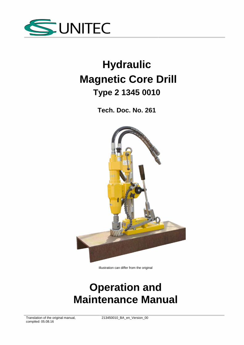
Hydraulic Magnetic Core Drill
Type 2 1345 0010
Tech. Doc. No. 261
Illustration can differ from the original
Operation and Maintenance Manual
H y d r a u l i c Magne t ic Core Dr i l l 2 1345 0010
Translation of the original manual, compiled: 05.08.16
213450010_BA_en_Version_00 Page 1 of 26
Directory
Page Signal Word and Symbol Definition 2 Technical Specification 3 Use 3 Product Specification 4 Identification 4 Installation 5 Startup 6-13Basic Safety Instructions 14Employer’s Obligations 14Operator‘s Obligations 14Symbol Definition for Safety Equipment and Accident Prevention 15Safety Instructions for avoiding safety hazards 16-19Maintenance and Upkeep 20-21Disassembly – Re-assembly 21Storage 22Disposal 22Environmental Regulations 22Troubleshooting 23Warranty and Liability 24Scope of delivery 24Declaration of Conformity 25
CS Unitec, Inc. • Toll-free: 800-700-5919 • Ph: 1-203-853-9522 • Email: [email protected] • www.csunitec.com
H y d r a u l i c Magne t ic Core Dr i l l 2 1345 0010
Translation of the original manual, compiled: 05.08.16
213450010_BA_en_Version_00 Page 2 of 26
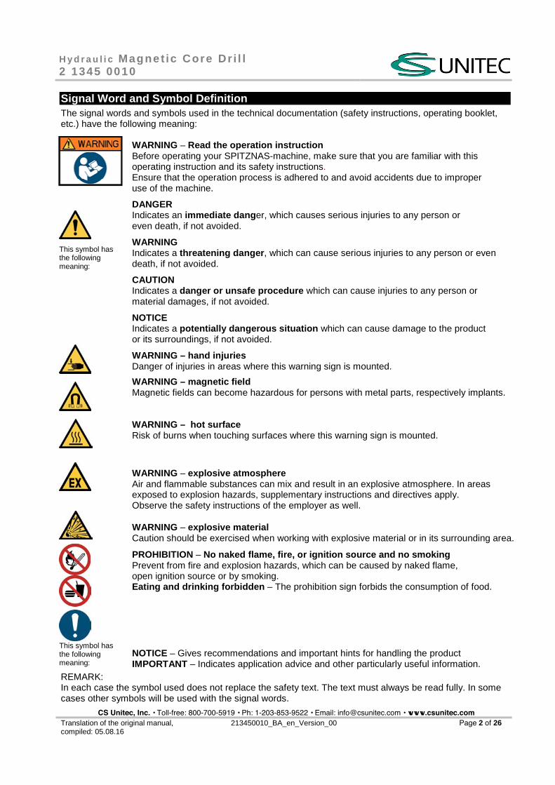
Signal Word and Symbol Definition The signal words and symbols used in the technical documentation (safety instructions, operating booklet, etc.) have the following meaning:
WARNING – Read the operation instruction Before operating your SPITZNAS-machine, make sure that you are familiar with this operating instruction and its safety instructions. Ensure that the operation process is adhered to and avoid accidents due to improper use of the machine.
This symbol has the following meaning:
DANGER Indicates an immediate dang er, which causes serious injuries to any person or even death, if not avoided.
WARNING Indicates a threatening danger , which can cause serious injuries to any person or even death, if not avoided.
CAUTION Indicates a danger or unsafe procedure which can cause injuries to any person or material damages, if not avoided.
NOTICE Indicates a potentially dangerous situation which can cause damage to the product or its surroundings, if not avoided.
WARNING – hand injuries Danger of injuries in areas where this warning sign is mounted.
WARNING – magnetic field Magnetic fields can become hazardous for persons with metal parts, respectively implants.
WARNING – hot surface Risk of burns when touching surfaces where this warning sign is mounted.
WARNING – explosive atmosphere Air and flammable substances can mix and result in an explosive atmosphere. In areas exposed to explosion hazards, supplementary instructions and directives apply. Observe the safety instructions of the employer as well.
WARNING – explosive material Caution should be exercised when working with explosive material or in its surrounding area.
PROHIBITION – No naked flame, fire, or ignition source and no smoking Prevent from fire and explosion hazards, which can be caused by naked flame, open ignition source or by smoking. Eating and drinking forbidden – The prohibition sign forbids the consumption of food.
This symbol has the following meaning:
NOTICE – Gives recommendations and important hints for handling the product IMPORTANT – Indicates application advice and other particularly useful information.
REMARK: In each case the symbol used does not replace the safety text. The text must always be read fully. In some cases other symbols will be used with the signal words.
CS Unitec, Inc. • Toll-free: 800-700-5919 • Ph: 1-203-853-9522 • Email: [email protected] • www.csunitec.com
H y d r a u l i c Magne t ic Core Dr i l l 2 1345 0010
Translation of the original manual, compiled: 05.08.16
213450010_BA_en_Version_00 Page 3 of 26
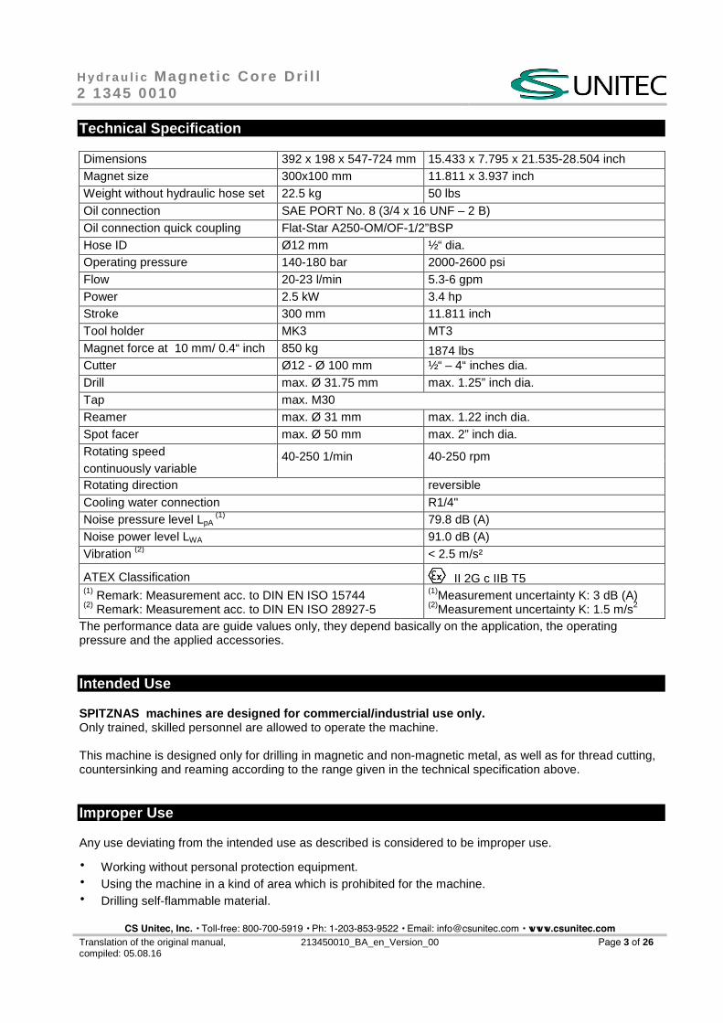
Technical Specification
Dimensions 392 x 198 x 547-724 mm 15.433 x 7.795 x 21.535-28.504 inch Magnet size 300x100 mm 11.811 x 3.937 inch Weight without hydraulic hose set 22.5 kg 50 lbs Oil connection SAE PORT No. 8 (3/4 x 16 UNF – 2 B) Oil connection quick coupling Flat-Star A250-OM/OF-1/2”BSP Hose ID Ø12 mm ½“ dia. Operating pressure 140-180 bar 2000-2600 psi Flow 20-23 l/min 5.3-6 gpm Power 2.5 kW 3.4 hp Stroke 300 mm 11.811 inch Tool holder MK3 MT3 Magnet force at 10 mm/ 0.4“ inch 850 kg 1874 lbs Cutter Ø12 - Ø 100 mm ½“ – 4“ inches dia. Drill max. Ø 31.75 mm max. 1.25” inch dia. Tap max. M30 Reamer max. Ø 31 mm max. 1.22 inch dia. Spot facer max. Ø 50 mm max. 2” inch dia. Rotating speed 40-250 1/min 40-250 rpmcontinuously variable Rotating direction reversible Cooling water connection R1/4" Noise pressure level LpA
(1) 79.8 dB (A) Noise power level LWA 91.0 dB (A) Vibration (2) < 2.5 m/s²
ATEX Classification II 2G c IIB T5 (1) Remark: Measurement acc. to DIN EN ISO 15744(2) Remark: Measurement acc. to DIN EN ISO 28927-5
(1)Measurement uncertainty K: 3 dB (A) (2)Measurement uncertainty K: 1.5 m/s2
The performance data are guide values only, they depend basically on the application, the operating pressure and the applied accessories.
Intended Use
SPITZNAS machines are designed for commercial/industrial use only. Only trained, skilled personnel are allowed to operate the machine.
This machine is designed only for drilling in magnetic and non-magnetic metal, as well as for thread cutting, countersinking and reaming according to the range given in the technical specification above.
Improper Use
Any use deviating from the intended use as described is considered to be improper use.
� Working without personal protection equipment. � Using the machine in a kind of area which is prohibited for the machine. � Drilling self-flammable material.
CS Unitec, Inc. • Toll-free: 800-700-5919 • Ph: 1-203-853-9522 • Email: [email protected] • www.csunitec.com
H y d r a u l i c Magne t ic Core Dr i l l 2 1345 0010
Translation of the original manual, compiled: 05.08.16
213450010_BA_en_Version_00 Page 4 of 26
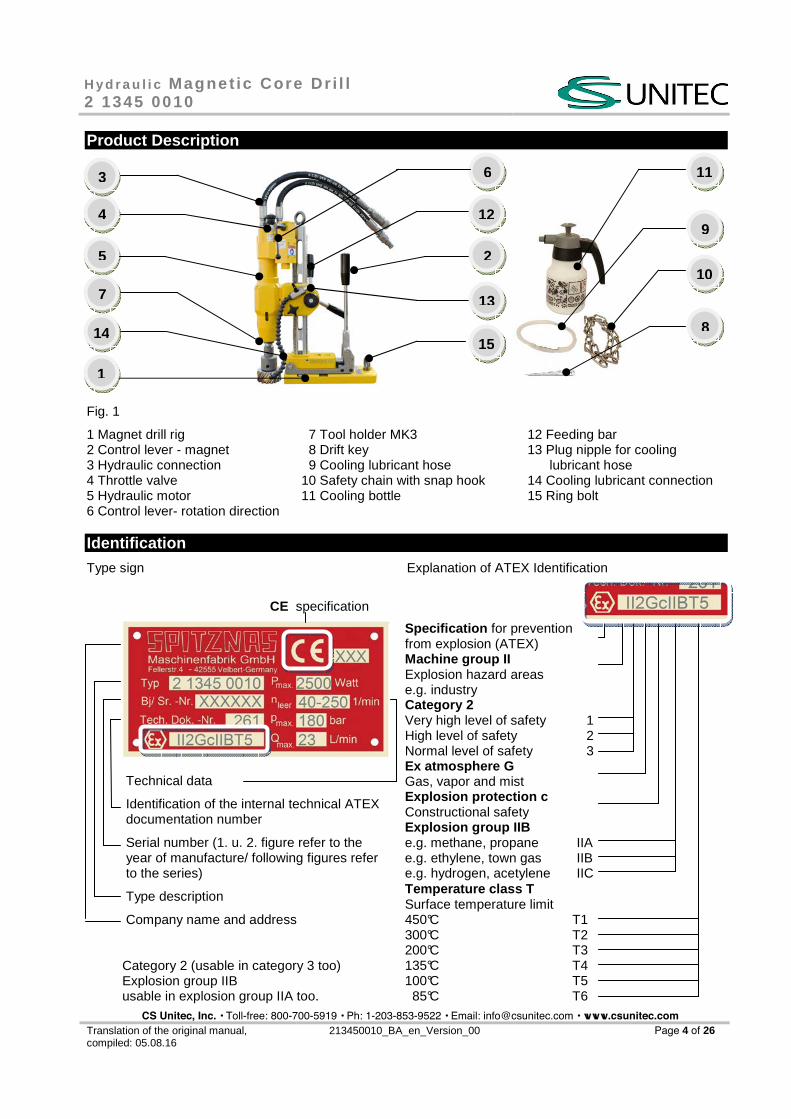
Product Description
Fig. 1
1 Magnet drill rig 2 Control lever - magnet 3 Hydraulic connection 4 Throttle valve 5 Hydraulic motor 6 Control lever- rotation direction
7 Tool holder MK3 8 Drift key 9 Cooling lubricant hose 10 Safety chain with snap hook 11 Cooling bottle
12 Feeding bar 13 Plug nipple for cooling lubricant hose 14 Cooling lubricant connection 15 Ring bolt
Identification
Type sign Explanation of ATEX Identification
CE specification
Technical data
Identification of the internal technical ATEX documentation number
Serial number (1. u. 2. figure refer to the year of manufacture/ following figures refer to the series)
Type description
Company name and address
Category 2 (usable in category 3 too) Explosion group IIB usable in explosion group IIA too.
Specification for prevention from explosion (ATEX) Machine group II Explosion hazard areas e.g. industryCategory 2Very high level of safetyHigh level of safetyNormal level of safety
1 2 3
Ex atmosphere GGas, vapor and mistExplosion protection cConstructional safetyExplosion group IIBe.g. methane, propanee.g. ethylene, town gase.g. hydrogen, acetylene
IIA IIB IIC
Temperatur e class TSurface temperature limit450°C T1 300°C T2 200°C T3 135°C T4 100°C T5 85°C T6
116
9
8
4
3
5
1
7
210
1415
12
13
CS Unitec, Inc. • Toll-free: 800-700-5919 • Ph: 1-203-853-9522 • Email: [email protected] • www.csunitec.com
H y d r a u l i c Magne t ic Core Dr i l l 2 1345 0010
Translation of the original manual, compiled: 05.08.16
213450010_BA_en_Version_00 Page 5 of 26
Installation
Requirements to the hydraulic system The following is required for an optimum performance of the hydraulic magnetic core drill:
� Provide a volume flow of max. 23 l/min at an operating pressure of 140 to180 bar, � the system should not have more than 17 bar back pressure, � the hydraulic system should have sufficient heat rejection capacity to limit the maximum oil temperature
to 60 °C at the maximum expected ambient temperatur e.
It is recommended:
� That the filter elements are sized for a volume flow of at least 114 lpm for cold temperature startup and for maximum dirt holding capacity,
� that the hydraulic system should have a minimum of 10 to 25 micron of full-flow filtration.
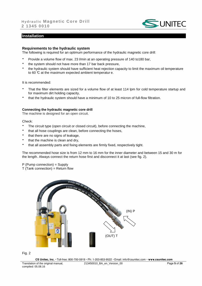
Conn ecting the hydraulic magnetic core drill The machine is designed for an open circuit.
Check: � The circuit type (open circuit or closed circuit), before connecting the machine, � that all hose couplings are clean, before connecting the hoses, � that there are no signs of leakage, � that the machine is clean and dry, � that all assembly parts and fixing elements are firmly fixed, respectively tight.
The recommended hose size is from 12 mm to 16 mm for the inner diameter and between 15 and 30 m for the length. Always connect the return hose first and disconnect it at last (see fig. 2).
P (Pump connection) = Supply T (Tank connection) = Return flow
Fig. 2
(IN) P
(OUT) T
CS Unitec, Inc. • Toll-free: 800-700-5919 • Ph: 1-203-853-9522 • Email: [email protected] • www.csunitec.com
H y d r a u l i c Magne t ic Core Dr i l l 2 1345 0010
Translation of the original manual, compiled: 05.08.16
213450010_BA_en_Version_00 Page 6 of 26
Startup
Before using the machine, please read these instructions.
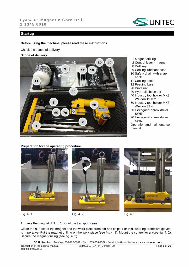
Check the scope of delivery.
Scope of delivery: 1 Magnet drill rig 2 Control lever - magnet 8 Drift key 9 Cooling lubricant hose 10 Safety chain with snap hook 11 Cooling bottle 12 Feeding bars 20 Drive unit 30 Hydraulic hose set 40 Industry tool holder MK3 Weldon 19 mm 50 Industry tool holder MK3 Weldon 32 mm 60 Hexagonal screw driver SW5 70 Hexagonal screw driver SW6 Operation and maintenance manual
Preparation for the operating procedure
Fig. 4. 1 Fig. 4. 2 Fig. 4. 3
1. Take the magnet drill rig 1 out of the transport case.
Clean the surface of the magnet and the work piece from dirt and chips. For this, wearing protective gloves is imperative. Put the magnet drill rig on the work piece (see fig. 4. 1). Mount the control lever (see fig. 4. 2). Secure the magnet drill rig (see fig. 4. 3).
1
10
8
11
20
30
12
2
4050
9
7060
CS Unitec, Inc. • Toll-free: 800-700-5919 • Ph: 1-203-853-9522 • Email: [email protected] • www.csunitec.com
H y d r a u l i c Magne t ic Core Dr i l l 2 1345 0010
Translation of the original manual, compiled: 05.08.16
213450010_BA_en_Version_00 Page 7 of 26
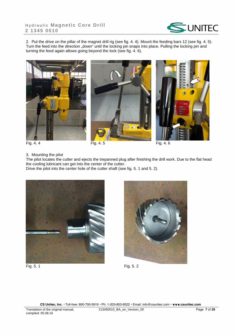
2. Put the drive on the pillar of the magnet drill rig (see fig. 4. 4). Mount the feeding bars 12 (see fig. 4. 5).Turn the feed into the direction „down“ until the locking pin snaps into place. Pulling the locking pin andturning the feed again allows going beyond the lock (see fig. 4. 6).
Fig. 4. 4 Fig. 4. 5 Fig. 4. 6
3. Mounting the pilotThe pilot locates the cutter and ejects the trepanned plug after finishing the drill work. Due to the flat headthe cooling lubricant can get into the center of the cutter.Drive the pilot into the center hole of the cutter shaft (see fig. 5. 1 and 5. 2).
Fig. 5. 1 Fig. 5. 2
CS Unitec, Inc. • Toll-free: 800-700-5919 • Ph: 1-203-853-9522 • Email: [email protected] • www.csunitec.com
H y d r a u l i c Magne t ic Core Dr i l l 2 1345 0010
Translation of the original manual, compiled: 05.08.16
213450010_BA_en_Version_00 Page 8 of 26
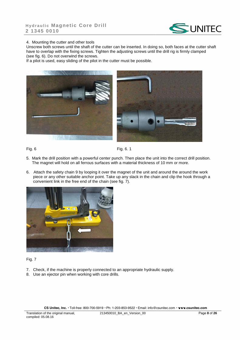
4. Mounting the cutter and other toolsUnscrew both screws until the shaft of the cutter can be inserted. In doing so, both faces at the cutter shafthave to overlap with the fixing screws. Tighten the adjusting screws until the drill rig is firmly clamped(see fig. 6). Do not overwind the screws.If a pilot is used, easy sliding of the pilot in the cutter must be possible.
5. Mark the drill position with a powerful center punch. Then place the unit into the correct drill position.The magnet will hold on all ferrous surfaces with a material thickness of 10 mm or more.
6. Attach the safety chain 9 by looping it over the magnet of the unit and around the around the workpiece or any other suitable anchor point. Take up any slack in the chain and clip the hook through aconvenient link in the free end of the chain (see fig. 7).
7. Check, if the machine is properly connected to an appropriate hydraulic supply.8. Use an ejector pin when working with core drills.
Fig. 6 Fig. 6. 1
Fig. 7
CS Unitec, Inc. • Toll-free: 800-700-5919 • Ph: 1-203-853-9522 • Email: [email protected] • www.csunitec.com
H y d r a u l i c Magne t ic Core Dr i l l 2 1345 0010
Translation of the original manual, compiled: 05.08.16
213450010_BA_en_Version_00 Page 9 of 26
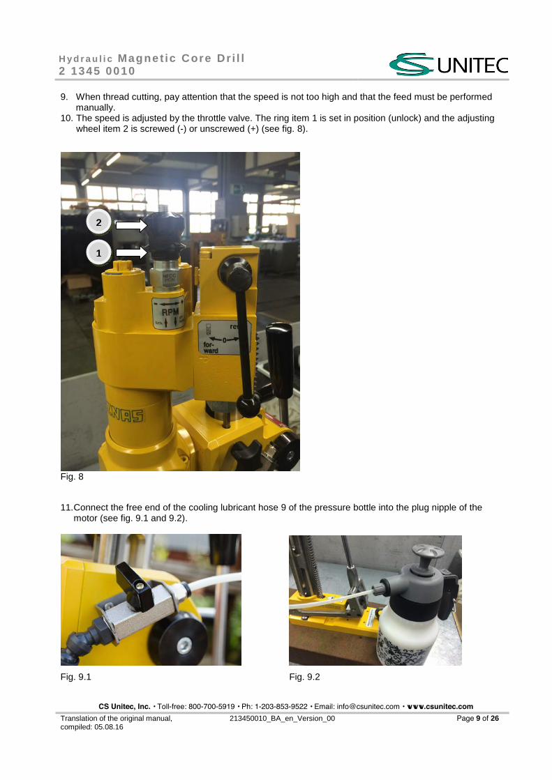
9. When thread cutting, pay attention that the speed is not too high and that the feed must be performedmanually.
10. The speed is adjusted by the throttle valve. The ring item 1 is set in position (unlock) and the adjustingwheel item 2 is screwed (-) or unscrewed (+) (see fig. 8).
11. Connect the free end of the cooling lubricant hose 9 of the pressure bottle into the plug nipple of themotor (see fig. 9.1 and 9.2).
Fig. 9.1 Fig. 9.2
Fig. 8
1
2
CS Unitec, Inc. • Toll-free: 800-700-5919 • Ph: 1-203-853-9522 • Email: [email protected] • www.csunitec.com
H y d r a u l i c Magne t ic Core Dr i l l 2 1345 0010
Translation of the original manual, compiled: 05.08.16
213450010_BA_en_Version_00 Page 10 of 26
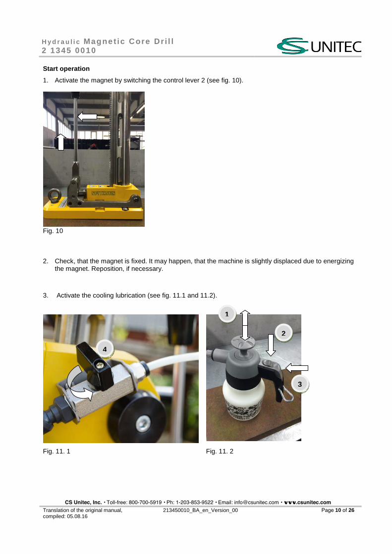
Start operation
1. Activate the magnet by switching the control lever 2 (see fig. 10).
Fig. 10
2. Check, that the magnet is fixed. It may happen, that the machine is slightly displaced due to energizingthe magnet. Reposition, if necessary.
3. Activate the cooling lubrication (see fig. 11.1 and 11.2).
Fig. 11. 1 Fig. 11. 2
1
2
3
4
CS Unitec, Inc. • Toll-free: 800-700-5919 • Ph: 1-203-853-9522 • Email: [email protected] • www.csunitec.com
H y d r a u l i c Magne t ic Core Dr i l l 2 1345 0010
Translation of the original manual, compiled: 05.08.16
213450010_BA_en_Version_00 Page 11 of 26
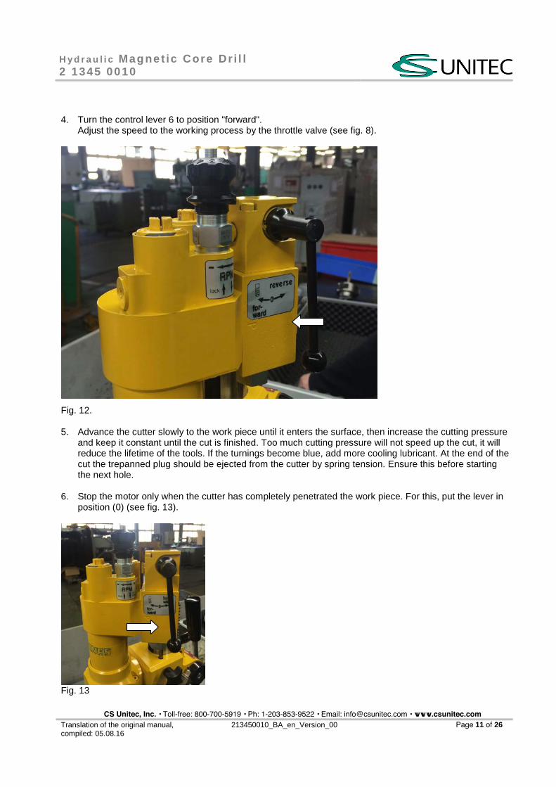
4. Turn the control lever 6 to position "forward".Adjust the speed to the working process by the throttle valve (see fig. 8).
Fig. 12.
5. Advance the cutter slowly to the work piece until it enters the surface, then increase the cutting pressureand keep it constant until the cut is finished. Too much cutting pressure will not speed up the cut, it willreduce the lifetime of the tools. If the turnings become blue, add more cooling lubricant. At the end of thecut the trepanned plug should be ejected from the cutter by spring tension. Ensure this before startingthe next hole.
6. Stop the motor only when the cutter has completely penetrated the work piece. For this, put the lever inposition (0) (see fig. 13).
Fig. 13
CS Unitec, Inc. • Toll-free: 800-700-5919 • Ph: 1-203-853-9522 • Email: [email protected] • www.csunitec.com
H y d r a u l i c Magne t ic Core Dr i l l 2 1345 0010
Translation of the original manual, compiled: 05.08.16
213450010_BA_en_Version_00 Page12 of 26
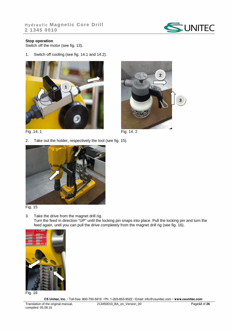
Stop operation Switch off the motor (see fig. 13).
1. Switch off cooling (see fig. 14.1 and 14.2).
Fig .14. 1 Fig. 14. 2
2. Take out the holder, respectively the tool (see fig. 15).
Fig. 15
3. Take the drive from the magnet drill rig.Turn the feed in direction “UP” until the locking pin snaps into place. Pull the locking pin and turn thefeed again, until you can pull the drive completely from the magnet drill rig (see fig. 16).
Fig. 16
1
3
2
CS Unitec, Inc. • Toll-free: 800-700-5919 • Ph: 1-203-853-9522 • Email: [email protected] • www.csunitec.com
H y d r a u l i c Magne t ic Core Dr i l l 2 1345 0010
Translation of the original manual, compiled: 05.08.16
213450010_BA_en_Version_00 Page13 of 26
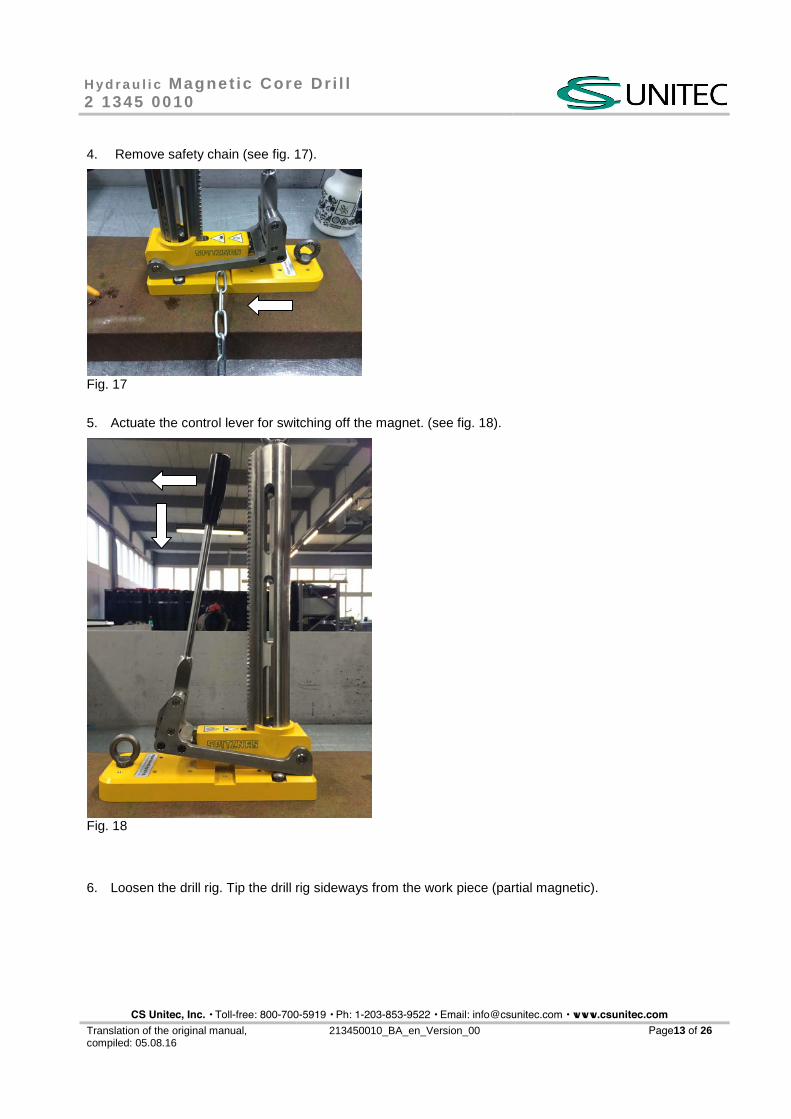
4. Remove safety chain (see fig. 17).
Fig. 17
5. Actuate the control lever for switching off the magnet. (see fig. 18).
Fig. 18
6. Loosen the drill rig. Tip the drill rig sideways from the work piece (partial magnetic).
CS Unitec, Inc. • Toll-free: 800-700-5919 • Ph: 1-203-853-9522 • Email: [email protected] • www.csunitec.com
H y d r a u l i c Magne t ic Core Dr i l l 2 1345 0010
Translation of the original manual, compiled: 05.08.16
213450010_BA_en_Version_00 Page 14 of 26
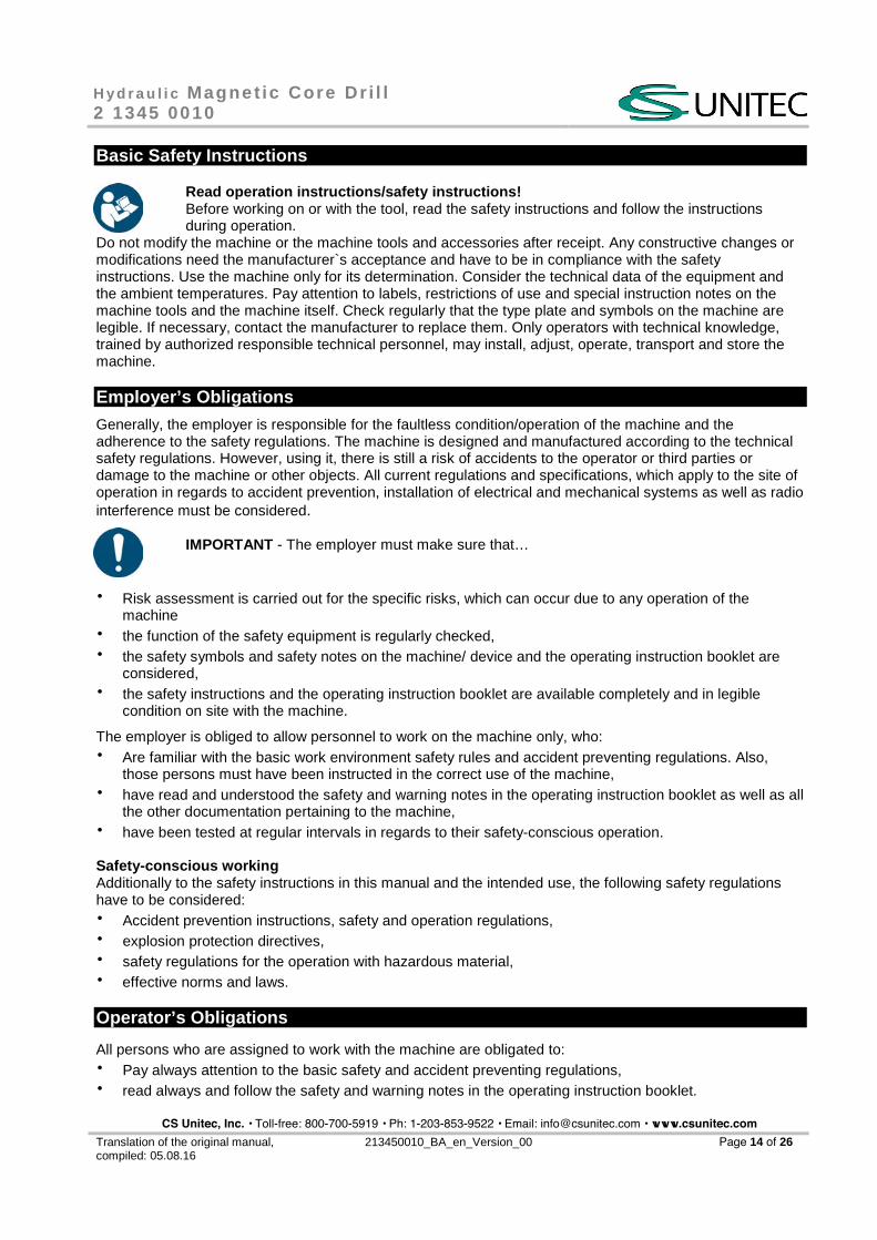
Basic Safety Instructions
Read operation instructions/safety instructions! Before working on or with the tool, read the safety instructions and follow the instructions during operation.
Do not modify the machine or the machine tools and accessories after receipt. Any constructive changes or modifications need the manufacturer`s acceptance and have to be in compliance with the safety instructions. Use the machine only for its determination. Consider the technical data of the equipment and the ambient temperatures. Pay attention to labels, restrictions of use and special instruction notes on the machine tools and the machine itself. Check regularly that the type plate and symbols on the machine are legible. If necessary, contact the manufacturer to replace them. Only operators with technical knowledge, trained by authorized responsible technical personnel, may install, adjust, operate, transport and store the machine.
Employer’s Obligations
Generally, the employer is responsible for the faultless condition/operation of the machine and the adherence to the safety regulations. The machine is designed and manufactured according to the technical safety regulations. However, using it, there is still a risk of accidents to the operator or third parties or damage to the machine or other objects. All current regulations and specifications, which apply to the site of operation in regards to accident prevention, installation of electrical and mechanical systems as well as radio interference must be considered.
IMPORTANT - The employer must make sure that…
� Risk assessment is carried out for the specific risks, which can occur due to any operation of the machine
� the function of the safety equipment is regularly checked, � the safety symbols and safety notes on the machine/ device and the operating instruction booklet are
considered, � the safety instructions and the operating instruction booklet are available completely and in legible
condition on site with the machine.
The employer is obliged to allow personnel to work on the machine only, who: � Are familiar with the basic work environment safety rules and accident preventing regulations. Also,
those persons must have been instructed in the correct use of the machine, � have read and understood the safety and warning notes in the operating instruction booklet as well as all
the other documentation pertaining to the machine, � have been tested at regular intervals in regards to their safety-conscious operation.
Safety-conscious working Additionally to the safety instructions in this manual and the intended use, the following safety regulations have to be considered: � Accident prevention instructions, safety and operation regulations, � explosion protection directives, � safety regulations for the operation with hazardous material, � effective norms and laws.
Operator’s Obligations
All persons who are assigned to work with the machine are obligated to: � Pay always attention to the basic safety and accident preventing regulations, � read always and follow the safety and warning notes in the operating instruction booklet.
CS Unitec, Inc. • Toll-free: 800-700-5919 • Ph: 1-203-853-9522 • Email: [email protected] • www.csunitec.com
H y d r a u l i c Magne t ic Core Dr i l l 2 1345 0010
Translation of the original manual, compiled: 05.08.16
213450010_BA_en_Version_00 Page 15 of 26
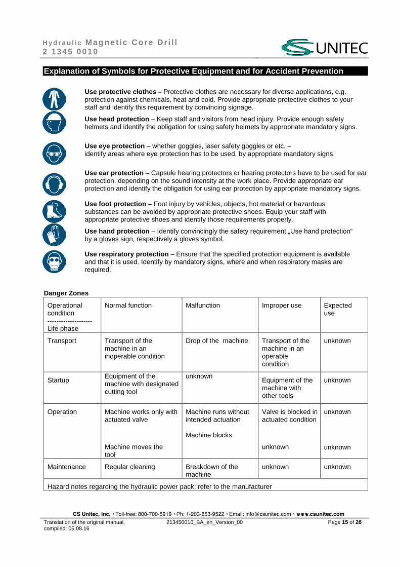
Explanation of Symbols for Protective Equipment and for Accident Prevention
Use protective clothes – Protective clothes are necessary for diverse applications, e.g. protection against chemicals, heat and cold. Provide appropriate protective clothes to your staff and identify this requirement by convincing signage.
Use head protection – Keep staff and visitors from head injury. Provide enough safety helmets and identify the obligation for using safety helmets by appropriate mandatory signs.
Use eye protection – whether goggles, laser safety goggles or etc. – identify areas where eye protection has to be used, by appropriate mandatory signs.
Use ear protection – Capsule hearing protectors or hearing protectors have to be used for ear protection, depending on the sound intensity at the work place. Provide appropriate ear protection and identify the obligation for using ear protection by appropriate mandatory signs.
Use foot protection – Foot injury by vehicles, objects, hot material or hazardous substances can be avoided by appropriate protective shoes. Equip your staff with appropriate protective shoes and identify those requirements properly.
Use hand protection – Identify convincingly the safety requirement „Use hand protection“ by a gloves sign, respectively a gloves symbol.
Use respiratory protection – Ensure that the specified protection equipment is available and that it is used. Identify by mandatory signs, where and when respiratory masks are required.
Danger Zones
Operational condition -------------------- Life phase
Normal function Malfunction Improper use Expected use
Transport Transport of the machine in an inoperable condition
Drop of the machine Transport of the machine in an operable condition
unknown
Startup Equipment of the machine with designated cutting tool
unknown Equipment of the machine with other tools
unknown
Operation Machine works only with actuated valve
Machine moves the tool
Machine runs without intended actuation
Machine blocks
Valve is blocked in actuated condition
unknown
unknown
unknown
Maintenance Regular cleaning Breakdown of the machine
unknown unknown
Hazard notes regarding the hydraulic power pack: refer to the manufacturer
CS Unitec, Inc. • Toll-free: 800-700-5919 • Ph: 1-203-853-9522 • Email: [email protected] • www.csunitec.com
H y d r a u l i c Magne t ic Core Dr i l l 2 1345 0010
Translation of the original manual, compiled: 05.08.16
213450010_BA_en_Version_00 Page 16 of 26
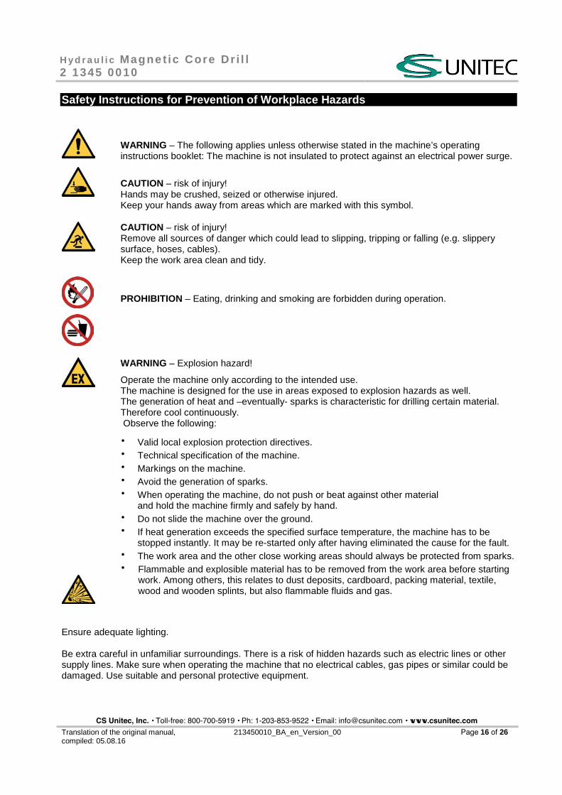
Safety Instructions for Prevention of Workplace Hazards
WARNING – The following applies unless otherwise stated in the machine’s operating instructions booklet: The machine is not insulated to protect against an electrical power surge.
CAUTION – risk of injury! Hands may be crushed, seized or otherwise injured. Keep your hands away from areas which are marked with this symbol.
CAUTION – risk of injury! Remove all sources of danger which could lead to slipping, tripping or falling (e.g. slippery surface, hoses, cables). Keep the work area clean and tidy.
PROHIBITION – Eating, drinking and smoking are forbidden during operation.
WARNING – Explosion hazard!
Operate the machine only according to the intended use. The machine is designed for the use in areas exposed to explosion hazards as well. The generation of heat and –eventually- sparks is characteristic for drilling certain material. Therefore cool continuously. Observe the following:
� Valid local explosion protection directives. � Technical specification of the machine. � Markings on the machine. � Avoid the generation of sparks. � When operating the machine, do not push or beat against other material
and hold the machine firmly and safely by hand. � Do not slide the machine over the ground. � If heat generation exceeds the specified surface temperature, the machine has to be
stopped instantly. It may be re-started only after having eliminated the cause for the fault. � The work area and the other close working areas should always be protected from sparks. � Flammable and explosible material has to be removed from the work area before starting
work. Among others, this relates to dust deposits, cardboard, packing material, textile, wood and wooden splints, but also flammable fluids and gas.
Ensure adequate lighting.
Be extra careful in unfamiliar surroundings. There is a risk of hidden hazards such as electric lines or other supply lines. Make sure when operating the machine that no electrical cables, gas pipes or similar could be damaged. Use suitable and personal protective equipment.
CS Unitec, Inc. • Toll-free: 800-700-5919 • Ph: 1-203-853-9522 • Email: [email protected] • www.csunitec.com
H y d r a u l i c Magne t ic Core Dr i l l 2 1345 0010
Translation of the original manual, compiled: 05.08.16
213450010_BA_en_Version_00 Page 17 of 26
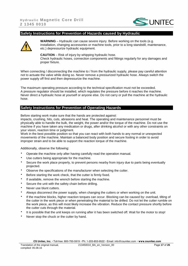
Safety Instructions for Prevention of Hazards caused by Hydraulic
WARNING – Hydraulic can cause severe injury. Before working on the tools (e.g. installation, changing accessories or machine tools, prior to a long standstill, maintenance, etc.) depressurize hydraulic equipment.
CAUTION – Risk of injury by whipping hydraulic hose. Check hydraulic hoses, connection components and fittings regularly for any damages and proper fixture.
When connecting / disconnecting the machine to / from the hydraulic supply, please pay careful attention not to actuate the valve while doing so. Never remove a pressurized hydraulic hose. Always switch the power supply off first and then depressurize the machine.
The maximum operating pressure according to the technical specification must not be exceeded. A pressure regulator should be installed, which regulates the pressure before it reaches the machine. Never direct a hydraulic hose at yourself or anyone else. Do not carry or pull the machine at the hydraulic hose.
Safety Instructions for Prevention of Operating Hazards
Before starting work make sure that the hands are protected against: impacts, crushing, hits, cuts, abrasions and heat. The operating and maintenance personnel must be physically able to handle the bulk, the weight, the power and/or the torque of the machine. Do not use the machine if you have taken any medication or drugs, after drinking alcohol or with any other constraints on your vision, reaction time or judgment. Work in the best possible position so that you can react with both hands to any normal or unexpected movements of the machine. Maintain a balanced body position and secure footing in order to avoid improper strain and to be able to support the reaction torque of the machine.
Additionally, observe the following:
� Operate the machine only after having carefully read the operation manual. � Use cutters being appropriate for the machine. � Secure the work place properly, to prevent persons nearby from injury due to parts being eventually
projected. � Observe the specifications of the manufacturer when selecting the cutter. � Before starting the work check, that the cutter is firmly fixed. � If available, remove the wrench before starting the machine. � Secure the unit with the safety chain before drilling. � Never use blunt cutters. � Always disconnect the power supply, when changing the cutters or when working on the unit. � If the machine blocks, higher reaction torques can occur. Blocking can be caused by: overload, tilting of
the cutter in the work piece or when penetrating the material to be drilled. Do not let the cutter rumble on the work piece, as this will most likely increase the vibration. Reduce the contact pressure shortly before the cutter cuts through the material.
� It is possible that the unit keeps on running after it has been switched off. Wait for the motor to stop! � Never stop the chuck or the cutter by hand.
CS Unitec, Inc. • Toll-free: 800-700-5919 • Ph: 1-203-853-9522 • Email: [email protected] • www.csunitec.com
H y d r a u l i c Magne t ic Core Dr i l l 2 1345 0010
Translation of the original manual, compiled: 05.08.16
213450010_BA_en_Version_00 Page 18 of 26
Safety Instructions for Prevention of Entanglement Hazards
CAUTION – Loose clothing, personal jewellery (e.g. necklace), scarves/ ties, long hair or gloves can get caught up in the machine tool or accessories and thus cause severe injuries (lack of breath by throttling, abrasions, skin injuries and/ or cuts and lacerations).
Wear suitable, close fitting work clothing! Wear a hair net, if you have long hair. When handling the machine, jewellery, necklaces, etc. have to be removed or are forbidden, respectively.
Safety Instructions for Prevention of Noise Hazards
Always wear hearing protection – This refers to the operator, as well as to any other person within the vicinity of the machine. Observe the instructions of the employer and of the professional association.
During operation high noise levels can cause permanent hearing problems such as tinnitus (ringing, buzzing, whistling or humming in the ears), hardness of hearing or even deafness. � If possible, use sound absorbing material, in order to avoid ringing noise at the work pieces.
Safety Instructions for Prevention of Vibration Hazards
Vibrations can cause damage of nerves and blood vasculares in hands and arms, therefore observe the following hints:
� Wear warm clothing and keep your hands warm and dry when working in cold conditions. Exercise hands and fingers regularly.
� Use stands and/or weight balancers, if possible. � When using a support (e.g. stand) make sure the machine is securely fixed. If no support is used, hold
the machine with light but safe grip in order to support the tool’s reaction torque. The tighter the grip the greater the risk of vibrations.
� Mount the machine as described in the operating instruction booklet in order to avoid unusually high vibrations.
� Stop work immediately, if you feel any numbness, tingling, pain or whitening of fingers or hands. Inform the employer and consult a doctor.
Safety Instructions for Prevention of Dust and Fume Hazards
Wear respiratory protection - Use respiratory protection as instructed by your employer and as required by occupational health and safety regulations. Dust and fumes being generated during work, respectively being eventually raised in the working environment can cause illness (e.g. cancer, birth defects, asthma and/ or dermatitis).
� Carry out risk assessment regarding dust and fume hazards and implement appropriate measures. � Keep the working place clean. � Keep in mind that working in certain materials may create dust and fumes causing a potentially
explosive atmosphere.
CS Unitec, Inc. • Toll-free: 800-700-5919 • Ph: 1-203-853-9522 • Email: [email protected] • www.csunitec.com
H y d r a u l i c Magne t ic Core Dr i l l 2 1345 0010
Translation of the original manual, compiled: 05.08.16
213450010_BA_en_Version_00 Page 19 of 26
Remark: Some types of metal may have toxic coatings. Please pay particular attention to avoid skin contact and breathing in, when working with those materials. Always use a protective mask. Ask your material supplier about special safety instructions and stick to them.
Safety Instructions for Prevention of Projectile Hazards
Wear impact -resistant safety goggles – This refers to the operator, as well as to the persons within the vicinity of the machine. Assess and determine the grade of protection required depending on the individual case. The risks to others should also be assessed at this time.
On overhead work, wear a safety helmet. If a work piece, accessories, inserted tools, or the tool itself breaks, there is danger from high velocity projectiles.
� Check all parts for damages before using the machine. � Replace damaged parts immediately. � When working on brittle material make sure that you are protected against harmful splinters.
Safety Instructions for Prevention of Accessory Hazards
Use only machine tools, accessories and consumables, which are recommended by the manufacturer. Make sure choosing the correct size and the correct type. Use only accessories, which are in proper condition.
CAUTION – Injury due to carelessness! If the machine is fixed to suspension equipment make sure that it is secure. Never hang the machine onto the supply line. � Separate the machine from any external energy source before changing the machine tool
or any accessory. � Avoid direct contact with the machine tool during and after use as it can be
hot or sharp. � Wear protective gloves when changing a tool or an accessory!
Notice: Defective/ inappropriate gloves can lead to injury. Wear only proper hand protection, adapted to the work place requirements. WARNING – Explosion hazard! When operating the machine in areas exposed to explosion hazards, use only accessories, respectively devices, which are ATEX approved and/or specified.
Safety Instructions for Prevention of Transport Hazards
ATTENTION – Improper Transport, injury due to parts falling down! Damage of the machine!
� Separate the machine form any external energy source before transportation. Check that the machine is undamaged and in proper condition.
� Never carry the machine at the supply line.
Wear worker’s protective shoes!
CS Unitec, Inc. • Toll-free: 800-700-5919 • Ph: 1-203-853-9522 • Email: [email protected] • www.csunitec.com
H y d r a u l i c Magne t ic Core Dr i l l 2 1345 0010
Translation of the original manual, compiled: 05.08.16
213450010_BA_en_Version_00 Page 20 of 26
Service and Maintenance
Basic Safety Instructions:
WARNING – Maintenance and repair work on hydraulic equipment. Hydraulic can cause severe injury. Observe legal regulations. Take precautions for persons and environment. Additionally, observe the following:
� Secure the machine against unintentional starting and let the machine cool down to the ambient temperature
� Protection against tipping, tumbling or falling down when assembling/ disassembling the machine/parts.
CAUTION – Skin exposure to hazardous dusts may cause severe dermatitis. Dust at the work place can be raised during the maintenance procedure and can be inhaled. Clean the machine and the work place before maintenance work.
WARNING – Danger of explosion! Generation of sparks during maintenance work!
Consider local safety regulations. Avoid use of force when disassembling and assembling the machine. Always do maintenance work outside hazardous medium.
PROHIBITION - Eating, drinking and smoking are forbidden during maintenance and repair work.
NOTICE – Use only original SPITZNAS spare parts , in order to avoid damages.
Otherwise you risk a decrease in machine performance and an increase in maintenance work. Check the adherence to the technical specifications according to the operation manual after each maintenance work.
IMPORTANT – There is no warranty for damages and liability is disclaimed, if non-original spare parts are used.
Maintenance Instruction Generally, hydraulic machines need little maintenance. If these rules are followed, the machine will have the expected durability and high reliability. Service life and performance of the machines are decisively determined by:
� The purity degree of the hydraulic oil, � the lubrication conditions and maintenance, � the regular control of the hydraulic filter/ the hydraulic fluid, as well as the regular checking of
the machine with regards to external damages.
Inspection and maintenance can be done by the operator.
Disassembly and re-assembly of the machine have to be executed by qualified staff only. Incorrect assembly can lead to danger of accident for the operator and to defects on the machine.
CS Unitec, Inc. • Toll-free: 800-700-5919 • Ph: 1-203-853-9522 • Email: [email protected] • www.csunitec.com
H y d r a u l i c Magne t ic Core Dr i l l 2 1345 0010
Translation of the original manual, compiled: 05.08.16
213450010_BA_en_Version_00 Page 21 of 26
After completing maintenance and repair work and before restarting production make sure that… � all materials, tools and other equipment which are required for maintenance or repairs have been
removed from the work area of the machine, � any fluid leaks have been removed, � all safety devices on the machine have proper function, � the oil level has been checked, if necessary, � fixtures of screw connections are tight, � removed covers, screens or filters were reinstalled.
The employer ensures that all maintenance, inspection and assembly work is done by authorized and qualified experts, who are appropriately informed by thorough study of the operating instruction.
Disassembly- Re-assembly
Maintenance and repair Disassembly and re-assembly should be done according to the exploded views, respectively the sectional drawings (see repair instruction). All work regarding disassembly and re-assembly, have to be executed by SPITZNAS or skilled staff only.
DANGER – Working with the machine without appropriate preparation and disregarding of instructions. Shut down the machine properly and let it cool down to the ambient temperature.
NOTICE – Special instructions apply for the repair of explosion-proof machines. Retrofits or modifications of the machine can affect the explosion protection. Therefore, they need the manufacturer’s acceptance. The explosion-proof machine is designed in the type of protection „c“ constructive safety. All work executed on the machine, influencing the explosion protection, e. g. repairs with mechanical machining, require an approval of an authorized expert or have to be done by the manufacturer. The internal structure must remain unmodified.
Our SPITZNAS-Service is available in case of damage and for all maintenance, repair and assembly work.
CS Unitec, Inc. • Toll-free: 800-700-5919 • Ph: 1-203-853-9522 • Email: [email protected] • www.csunitec.com
H y d r a u l i c Magne t ic Core Dr i l l 2 1345 0010
Translation of the original manual, compiled: 05.08.16
213450010_BA_en_Version_00 Page 22 of 26
Storage
Unused machines and machine tools should be kept in a dry, closed room. Keep them free from damaging influences such as damp, frost or large temperature fluctuations as well as mechanical damage.
Always store the machine in a way that important machine instructions, e. g. on stickers and signs, are legible.
NOTICE – Always connect the loose ends of the hoses with each other, if possible.
Disposal
Dispose of machine and worn out/defective machine tools according the local/national regulations. Fully disassemble the machine for the necessary disposal. Separate materials according to local environmental specifications.
Dispose environmentally hazardous greasing, cooling or cleaning agents in order to avoid environmental contamination.
Environmental Regulations
When working on or with the equipment, it is imperative to observe all legal requirements in regards to waste-disposal and proper recycling.
In particular during installation, repair and maintenance work, water damaging agents, such as
� lubricating grease and oil, � hydraulic fluid, � coolant,
solvent containing cleaning agents
must not leak into the ground or reach the sewage system. These materials must be stored, transported, contained and disposed of in suitable containers!
CS Unitec, Inc. • Toll-free: 800-700-5919 • Ph: 1-203-853-9522 • Email: [email protected] • www.csunitec.com
H y d r a u l i c Magne t ic Core Dr i l l 2 1345 0010
Translation of the original manual, compiled: 05.08.16
213450010_BA_en_Version_00 Page 23 of 26
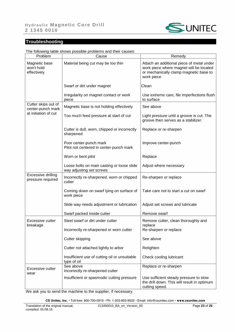
Troubleshooting
The following table shows possible problems and their causes: Problem Cause Remedy
Magnetic base won't hold effectively
Material being cut may be too thin
Swarf or dirt under magnet
Irregularity on magnet contact or work piece
Attach an additional piece of metal under work piece where magnet will be located or mechanically clamp magnetic base to work piece
Clean
Use extreme care, file imperfections flush to surface
Cutter skips out of center-punch mark at initiation of cut
Magnetic base is not holding effectively
Too much feed pressure at start of cut
Cutter is dull, worn, chipped or incorrectly sharpened
Poor center-punch mark Pilot not centered in center-punch mark
Worn or bent pilot
Loose bolts on main casting or loose slide way adjusting set screws
See above
Light pressure until a groove is cut. The groove then serves as a stabilizer.
Replace or re-sharpen
Improve center-punch
Replace
Adjust where necessary
Excessive drilling pressure required Incorrectly re-sharpened, worn or chipped
cutter
Coming down on swarf lying on surface of work piece
Slide way needs adjustment or lubrication
Swarf packed inside cutter
Re-sharpen or replace
Take care not to start a cut on swarf
Adjust set screws and lubricate
Remove swarf
Excessive cutter breakage
Steel swarf or dirt under cutter
Incorrectly re-sharpened or worn cutter
Cutter skipping
Cutter not attached tightly to arbor
Insufficient use of cutting oil or unsuitable type of oil
Remove cutter, clean thoroughly and replace Re-sharpen or replace
See above
Retighten
Check cooling lubricant
Excessive cutter wear
See above Incorrectly re-sharpened cutter
Insufficient or spasmodic cutting pressure
Replace or re-sharpen
Use sufficient steady pressure to slow the drill down. This will result in optimum cutting speed.
We ask you to send the machine to the supplier, if necessary.
CS Unitec, Inc. • Toll-free: 800-700-5919 • Ph: 1-203-853-9522 • Email: [email protected] • www.csunitec.com
H y d r a u l i c Magne t ic Core Dr i l l 2 1345 0010
Translation of the original manual, compiled: 05.08.16
213450010_BA_en_Version_00 Page 24 of 26
Warranty and Liability
Unless otherwise specified, our „General Sales Terms” apply. Warranty and liability claims in regards to persons or equipment damages are invalid, if one or more of the following causes apply:
� Improper use of the machine, � improper assembly, startup, operation or maintenance of the machine, � operation of the machine with defect safety devices or improperly fixed or non-functioning safety and
protection devices, � not considering of the instructions in the operating instruction booklet concerning transport, storage,
assembly, startup, operation, maintenance and setting up of the machine, � independent structural alterations or settings on the machine beyond the intended purpose, � inadequate supervision of wear parts, � improperly carried out repairs, inspections or maintenance, � catastrophic cases due to foreign objects, acts of god or other reasons which are beyond our control.
Scope of Delivery
Check, if the scope of delivery is complete: 1 Operation and maintenance manual 1 Hydraulic Magnetic Core Drill
CS Unitec, Inc. • Toll-free: 800-700-5919 • Ph: 1-203-853-9522 • Email: [email protected] • www.csunitec.com
H y d r a u l i c Magne t ic Core Dr i l l 2 1345 0010
Translation of the original manual, compiled: 05.08.16
213450010_BA_en_Version_00 Page 25 of 26
D e c l a r a t i o n o f c o n f o r m i t y
as defined in the European Union Machine Directive 2006/42/EC and in the EU-ATEX-Directive 2014/34/EU for usable machines
We, the company SPITZNAS Maschinenfabrik GmbH, Fellerstraße 4, 42555 Velbert–Langenberg, declare that the following product
Description: Hydraulic Magnetic Core Drill Model: 2 1345 0010
in the version supplied by us, complies with the European Union Machine Directive 2006/42/EC and the EU-Directive 2014/34/EU (ATEX – group II, category 2, G c IIB T 5).
Applied harmonized norms are: DIN EN ISO 12100 DIN EN ISO 11148-3 DIN EN 1127-1 DIN EN 13463-1 DIN EN 13463-5
According to section 13 (1) b) ii) of the directive 2014/34/EU the technical documentation is deposited under reference -Nr. 557/Ex-Ab 2238/14 at the following office;
TÜV Rheinland Industrie Service GmbH Moltkeplatz 1, 45138 Essen (Registration No. 0035 for the scope of the Directive 2014/34/EU)
Name of the authorized person for documentation: Mr. Simon Witt
Address of the authorized person for documentation: see manufacturer’s address
42555 Velbert, 05.08.16
CS Unitec, Inc. • Toll-free: 800-700-5919 • Ph: 1-203-853-9522 • Email: [email protected] • www.csunitec.com
H y d r a u l i c Magne t ic Core Dr i l l 2 1345 0010
Translation of the original manual, compiled: 05.08.16
213450010_BA_en_Version_00 Page 26 of 26
Note:
CS Unitec, Inc. • Toll-free: 800-700-5919 • Ph: 1-203-853-9522 • Email: [email protected] • www.csunitec.com

Translation of the original manual, compiled: 05.08.16
213450010_BA_en_Version_00
22 Harbor Ave, Norwalk, CT 06850 USA
Toll-free: 1-800-700-5919 (USA & Canada) Phone: 203-853-9522 (outside USA & Canada)
Fax: 203-853-9921 E-Mail: [email protected] Internet:
www.csunitec.com