Embed Size (px)
DESCRIPTION
Muhammad Safdar(2007-civil-48)
Citation preview
UET Hydraulic Engineering Lab
M.Safdar, 2007 – CIVIL - 48 Page 1
d1
d2
Experiment No. 4
To study the flow characteristic of a Hydraulic Jump
developed in lab flume.
Objective
1) To physically achieved the hydraulic jump in lab flume.
2) To measure the physically the dimension of hydraulic jump.
3) To calculate the energy losses through hydraulic jump.
4) To plot the water surface profile for hydraulic jump at various discharge.
Apparatus
I. S6 – Tilting / lab flume with manometer, slope adjusting scale and flow arrangement
II. Hook gauge
Related Theory:
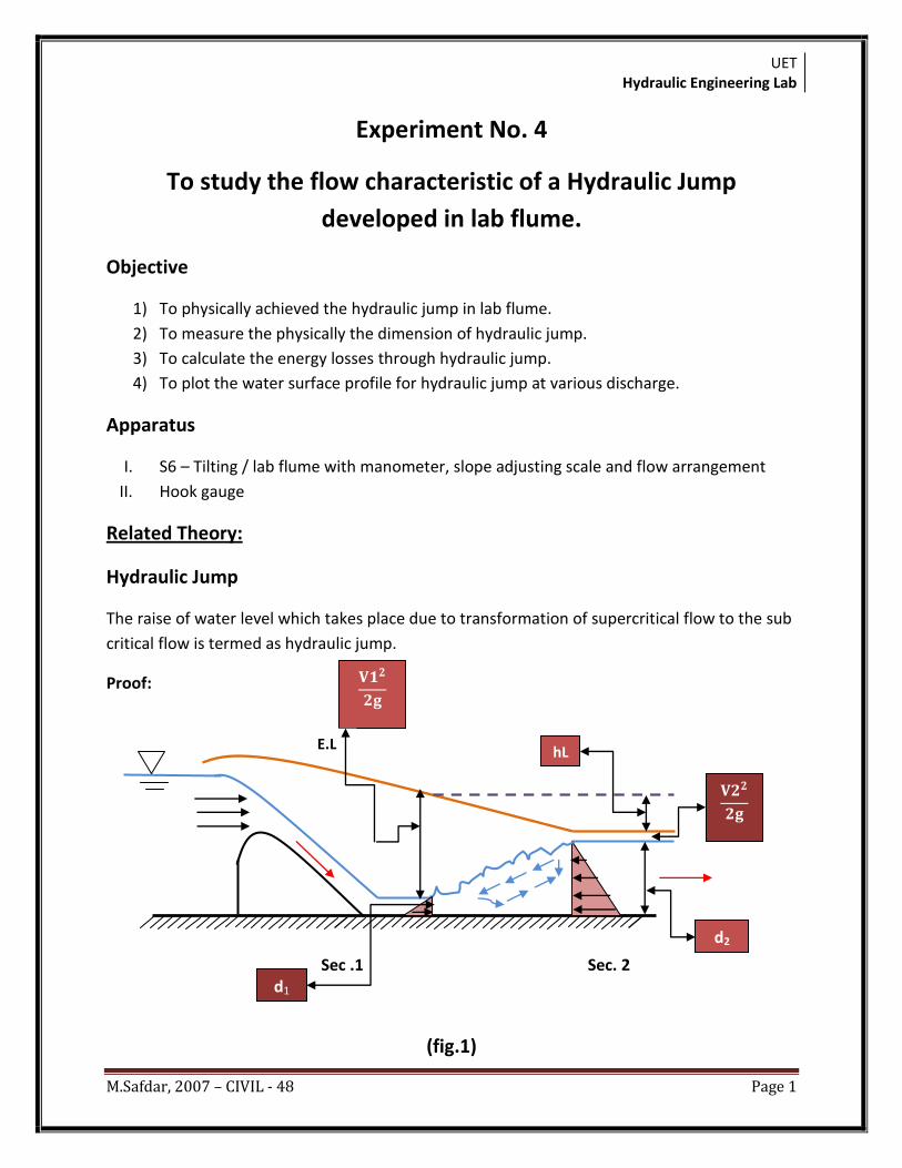
Hydraulic Jump
The raise of water level which takes place due to transformation of supercritical flow to the sub
critical flow is termed as hydraulic jump.
Proof:
Sec .1 Sec. 2
(fig.1)
E.L hL
UET Hydraulic Engineering Lab
M.Safdar, 2007 – CIVIL - 48 Page 2
d1
d2
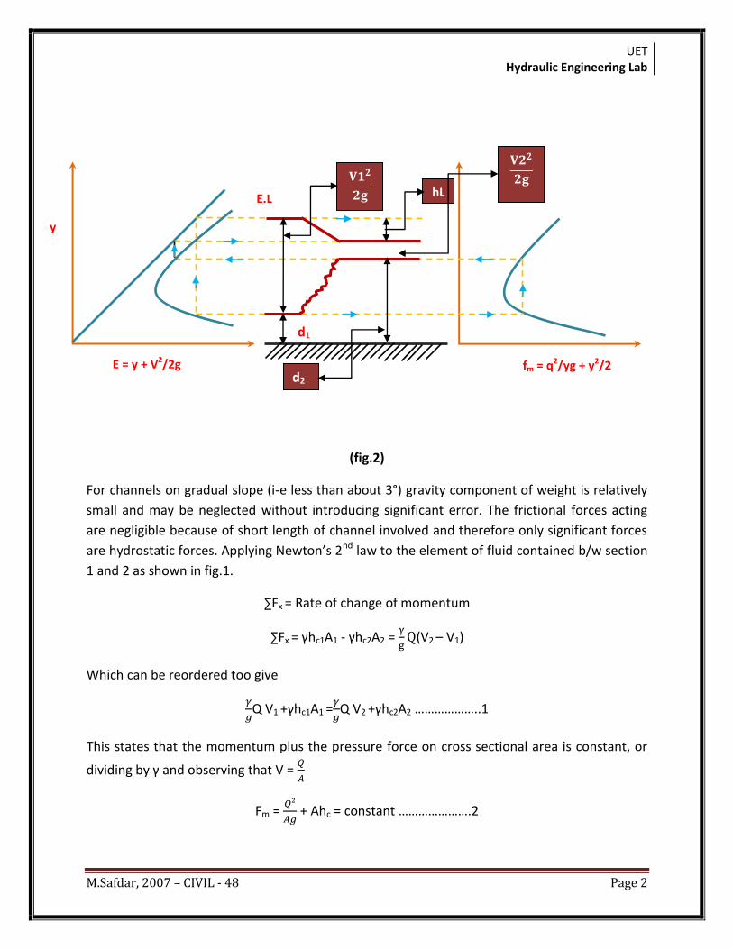
(fig.2)
For channels on gradual slope (i-e less than about 3°) gravity component of weight is relatively
small and may be neglected without introducing significant error. The frictional forces acting
are negligible because of short length of channel involved and therefore only significant forces
are hydrostatic forces. Applying Newton’s 2nd law to the element of fluid contained b/w section
1 and 2 as shown in fig.1.
∑Fx = Rate of change of momentum
∑Fx = γhc1A1 - γhc2A2 = (V2 – V1)
Which can be reordered too give
Q V1 +γhc1A1 = Q V2 +γhc2A2 ………………..1
This states that the momentum plus the pressure force on cross sectional area is constant, or
dividing by γ and observing that V =
Fm = + Ahc = constant ………………….2
y
E = y + V2/2g fm = q2/yg + y2/2
hL E.L
UET Hydraulic Engineering Lab
M.Safdar, 2007 – CIVIL - 48 Page 3
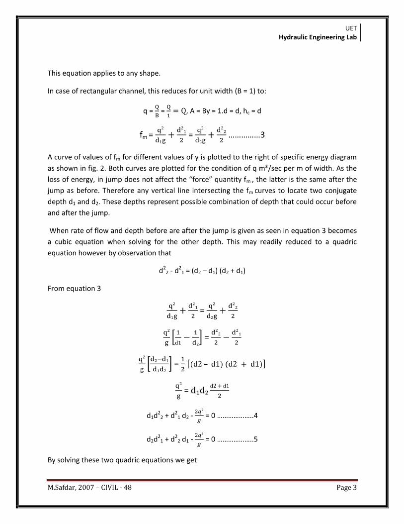
This equation applies to any shape.
In case of rectangular channel, this reduces for unit width (B = 1) to:
q = = , A = By = 1.d = d, hc = d
fm = = ……………3
A curve of values of fm for different values of y is plotted to the right of specific energy diagram
as shown in fig. 2. Both curves are plotted for the condition of q m³/sec per m of width. As the
loss of energy, in jump does not affect the “force” quantity fm , the latter is the same after the
jump as before. Therefore any vertical line intersecting the fm curves to locate two conjugate
depth d1 and d2. These depths represent possible combination of depth that could occur before
and after the jump.
When rate of flow and depth before are after the jump is given as seen in equation 3 becomes
a cubic equation when solving for the other depth. This may readily reduced to a quadric
equation however by observation that
d22 - d2
1 = (d2 – d1) (d2 + d1)
From equation 3
=
=
= –
=
d1d22 + d2
1 d2 - = 0 ………………..4
d2d21 + d2
2 d1 - = 0 ………………..5
By solving these two quadric equations we get
UET Hydraulic Engineering Lab
M.Safdar, 2007 – CIVIL - 48 Page 4
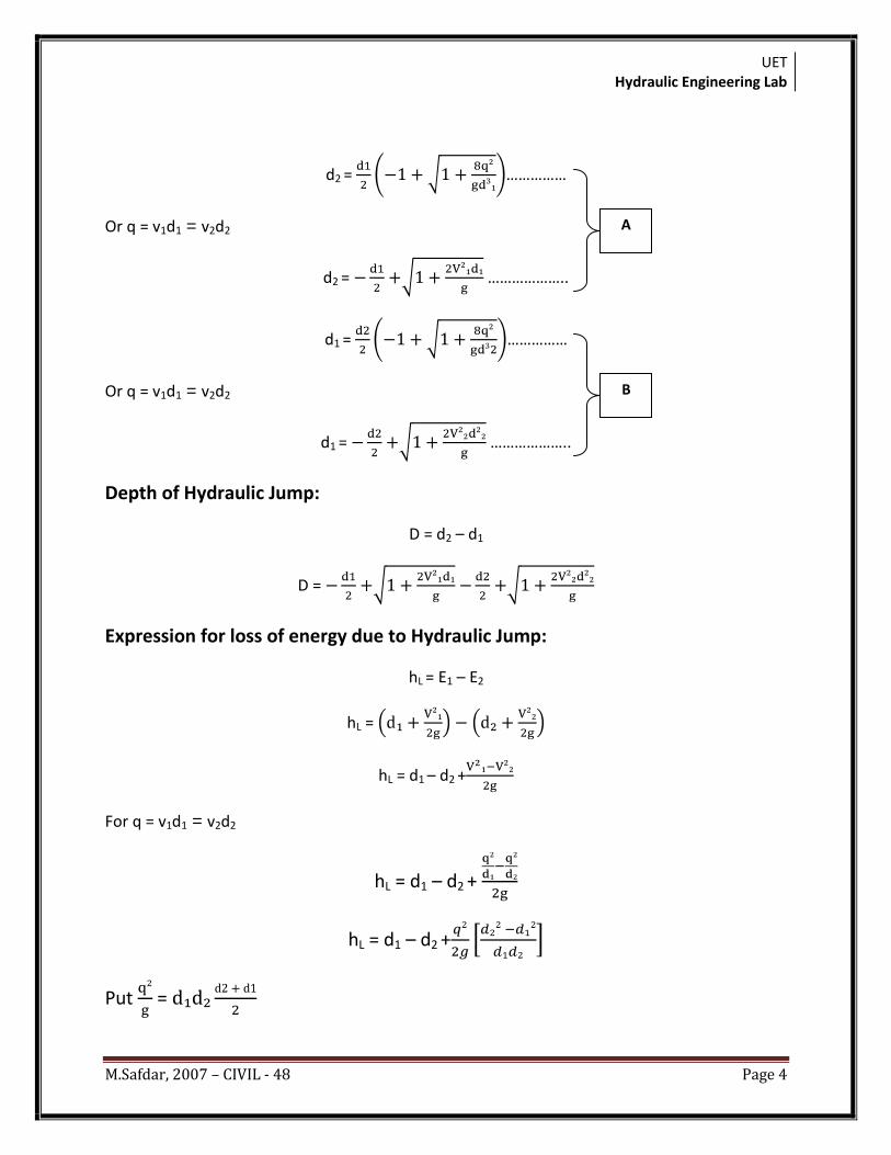
d2 = ……………
Or q = v1d1 = v2d2
d2 = ………………..
d1 = ……………
Or q = v1d1 = v2d2
d1 = ………………..
Depth of Hydraulic Jump:
D = d2 – d1
D =
Expression for loss of energy due to Hydraulic Jump:
hL = E1 – E2
hL =
hL = d1 – d2 +
For q = v1d1 = v2d2
hL = d1 – d2 +
hL = d1 – d2 +
Put =
A
B
UET Hydraulic Engineering Lab
M.Safdar, 2007 – CIVIL - 48 Page 5
Y2
d2
hL = d1 – d2 +
By simplifying we get
hL =
hL = …………………(C)
Length of Hydraulic Jump:
It is the length between two section where one section is taken before the hydraulic jump and
2nd section taken after the hydraulic jump is termed as the length of hydraulic jump.
For rectangular channel = length of hydraulic jump = 5-----7 times the depth of hydraulic jump.
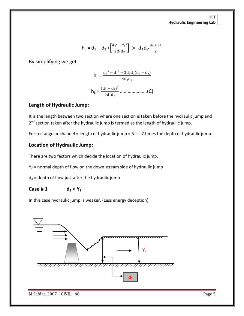
Location of Hydraulic Jump:
There are two factors which decide the location of hydraulic jump.
Y2 = normal depth of flow on the down stream side of hydraulic jump
d2 = depth of flow just after the hydraulic jump
Case # 1 d2 < Y2
In this case hydraulic jump is weaker. (Less energy deception)
UET Hydraulic Engineering Lab
M.Safdar, 2007 – CIVIL - 48 Page 6
Y2
d2
Y2
d2
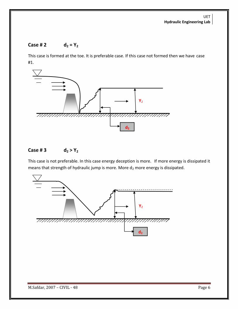
Case # 2 d2 = Y2
This case is formed at the toe. It is preferable case. If this case not formed then we have case
#1.
Case # 3 d2 > Y2
This case is not preferable. In this case energy deception is more. If more energy is dissipated it
means that strength of hydraulic jump is more. More d2 more energy is dissipated.
UET Hydraulic Engineering Lab
M.Safdar, 2007 – CIVIL - 48 Page 7
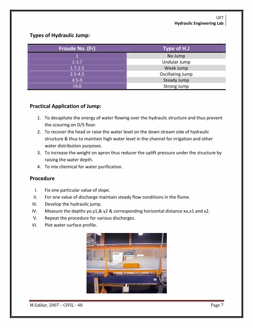
Types of Hydraulic Jump:
Froude No. (Fr) Type of H.J 1 No Jump
1-1.7 Undular Jump 1.7-2.5 Weak Jump 2.5-4.5 Oscillating Jump 4.5-9 Steady Jump >9.0 Strong Jump
Practical Application of Jump:
1. To decapitate the energy of water flowing over the hydraulic structure and thus prevent
the scouring on D/S floor.
2. To recover the head or raise the water level on the down stream side of hydraulic
structure & thus to maintain high water level in the channel for irrigation and other
water distribution purposes.
3. To increase the weight on apron thus reducer the uplift pressure under the structure by
raising the water depth.
4. To mix chemical for water purification.
Procedure
I. Fix one particular value of slope.
II. For one value of discharge maintain steady flow conditions in the flume.
III. Develop the hydraulic jump.
IV. Measure the depths yo,y1,& y2 & corresponding horizontal distance xo,x1 and x2.
V. Repeat the procedure for various discharges.
VI. Plot water surface profile.
UET Hydraulic Engineering Lab
M.Safdar, 2007 – CIVIL - 48 Page 8
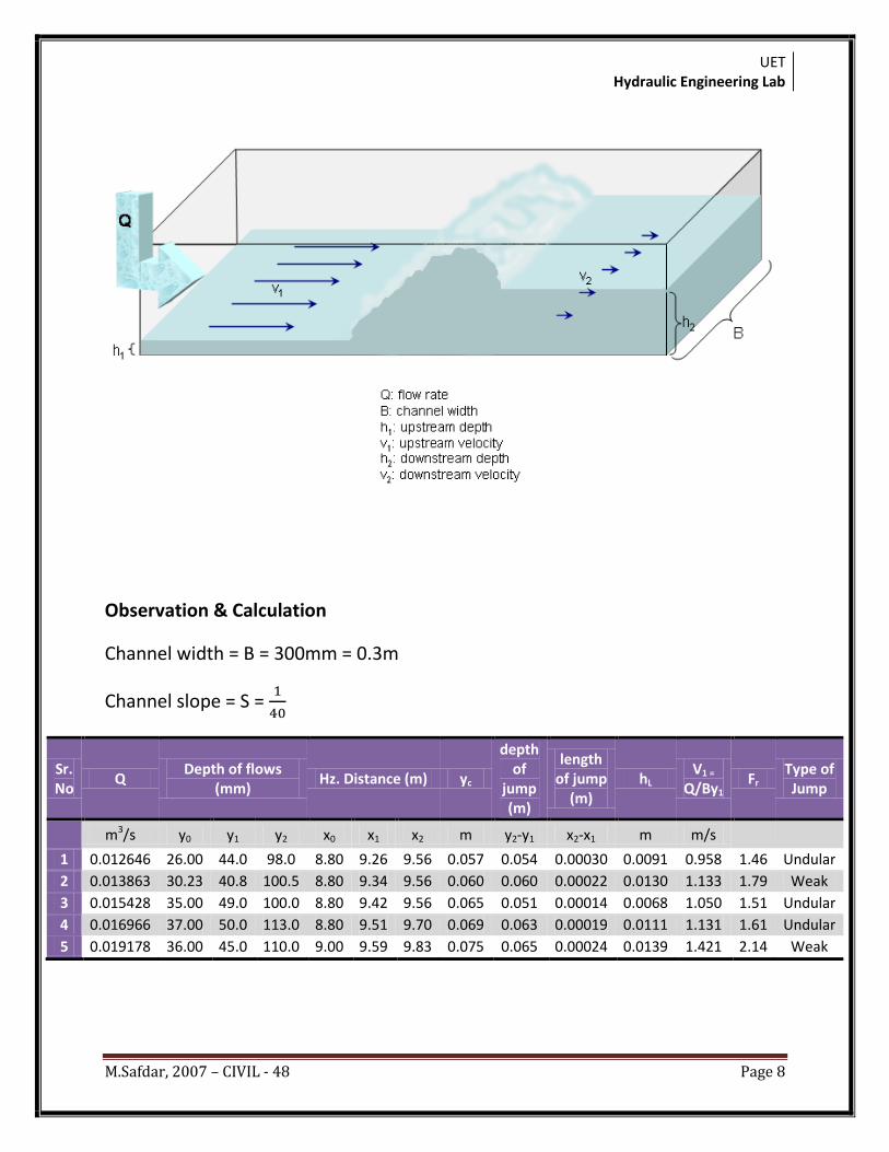
Observation & Calculation
Channel width = B = 300mm = 0.3m
Channel slope = S =
Sr. No
Q Depth of flows
(mm) Hz. Distance (m) yc
depth of
jump (m)
length of jump
(m) hL
V1 =
Q/By1 Fr
Type of Jump
m3/s y0 y1 y2 x0 x1 x2 m y2-y1 x2-x1 m m/s
1 0.012646 26.00 44.0 98.0 8.80 9.26 9.56 0.057 0.054 0.00030 0.0091 0.958 1.46 Undular
2 0.013863 30.23 40.8 100.5 8.80 9.34 9.56 0.060 0.060 0.00022 0.0130 1.133 1.79 Weak
3 0.015428 35.00 49.0 100.0 8.80 9.42 9.56 0.065 0.051 0.00014 0.0068 1.050 1.51 Undular
4 0.016966 37.00 50.0 113.0 8.80 9.51 9.70 0.069 0.063 0.00019 0.0111 1.131 1.61 Undular
5 0.019178 36.00 45.0 110.0 9.00 9.59 9.83 0.075 0.065 0.00024 0.0139 1.421 2.14 Weak
UET Hydraulic Engineering Lab
M.Safdar, 2007 – CIVIL - 48 Page 9
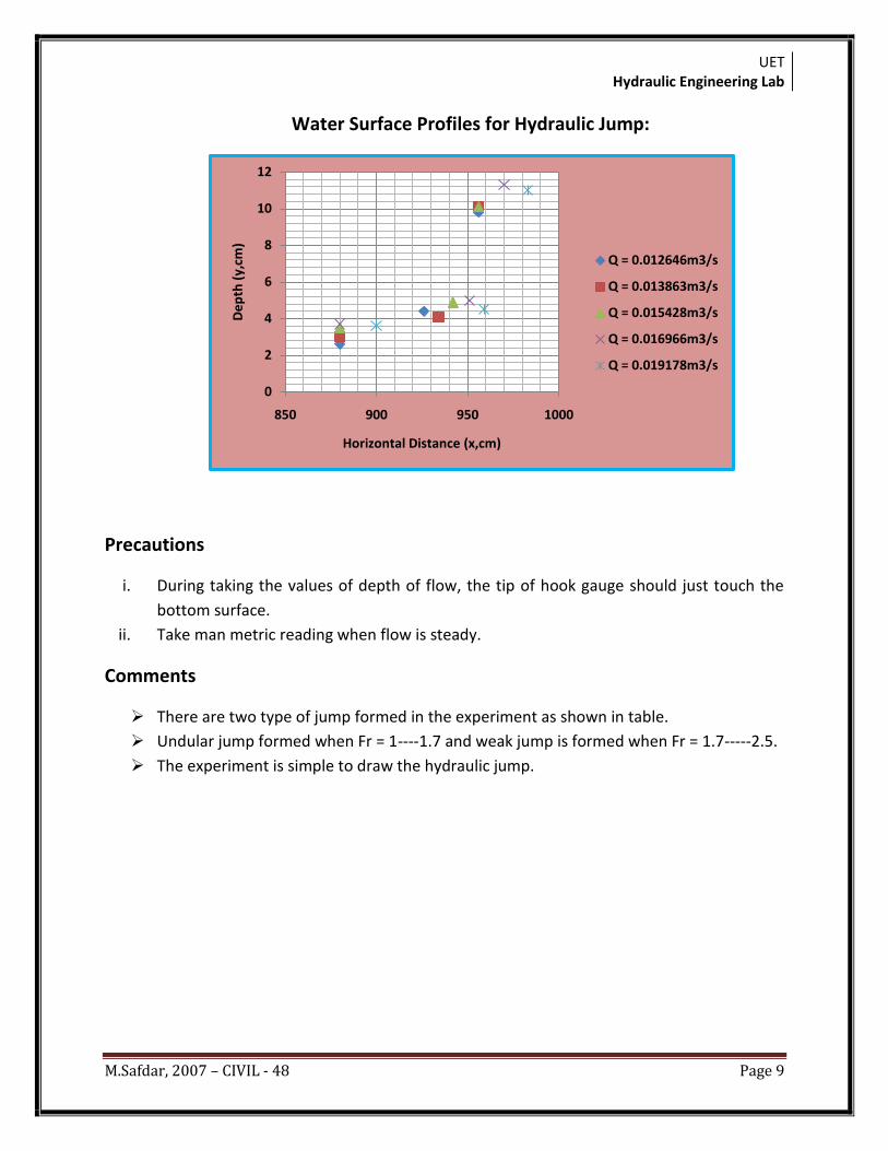
Water Surface Profiles for Hydraulic Jump:
Precautions
i. During taking the values of depth of flow, the tip of hook gauge should just touch the
bottom surface.
ii. Take man metric reading when flow is steady.
Comments
There are two type of jump formed in the experiment as shown in table.
Undular jump formed when Fr = 1----1.7 and weak jump is formed when Fr = 1.7-----2.5.
The experiment is simple to draw the hydraulic jump.
0
2
4
6
8
10
12
850 900 950 1000
De
pth
(y,
cm)
Horizontal Distance (x,cm)
Q = 0.012646m3/s
Q = 0.013863m3/s
Q = 0.015428m3/s
Q = 0.016966m3/s
Q = 0.019178m3/s


![Hydraulic Jump and Resultant Flow Choking in a Circular Sewer … · the hydraulic jump in a circular pipe [12,17]. Let alone the hydraulic jump in a circular pipe of steep slope](https://img.pdfslide.us/doc/110x75/5e6bfa6b4a9ff14e3c46306d/hydraulic-jump-and-resultant-flow-choking-in-a-circular-sewer-the-hydraulic-jump.jpg)