Embed Size (px)
Citation preview
cascade
corporationCascade is a Registered Trademark of Cascade Corporation
SER MANUALU
Manual Number 6891817-R2
Hydraulic Force Control
Carton Clamps
i 6891817-R2
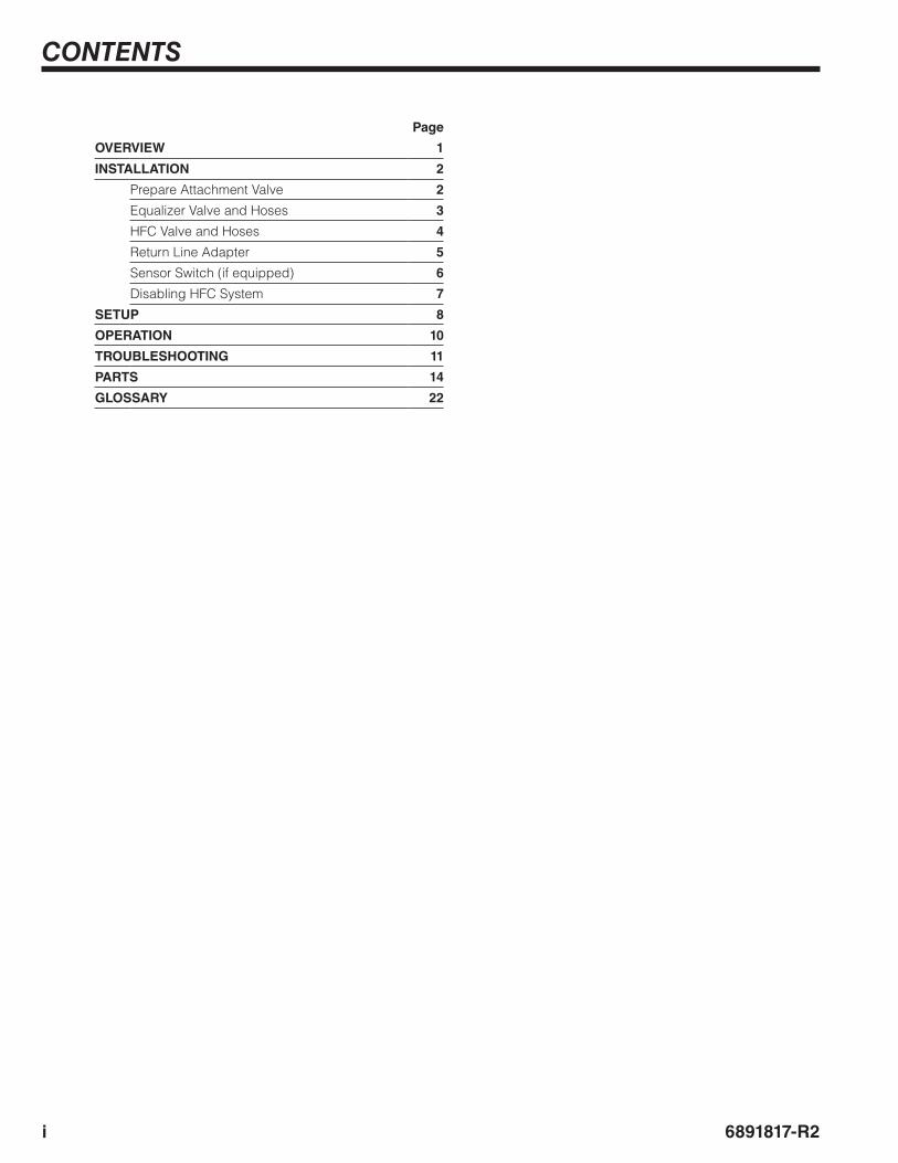
CONTENTS
Page
OVERVIEW 1
INSTALLATION 2
Prepare Attachment Valve 2
Equalizer Valve and Hoses 3
HFC Valve and Hoses 4
Return Line Adapter 5
Sensor Switch (if equipped) 6
Disabling HFC System 7
SETUP 8
OPERATION 10
TROUBLESHOOTING 11
PARTS 14
GLOSSARY 22
16891817-R2
OVERVIEW
HFC
MAST
TRU
CK
V6
V7
SS OUT 2
TP4
SS OUT 1
OR
OR /CKCL2
OP2
V3
TP1
TP2
V8
V2
T IN
AC3238.eps
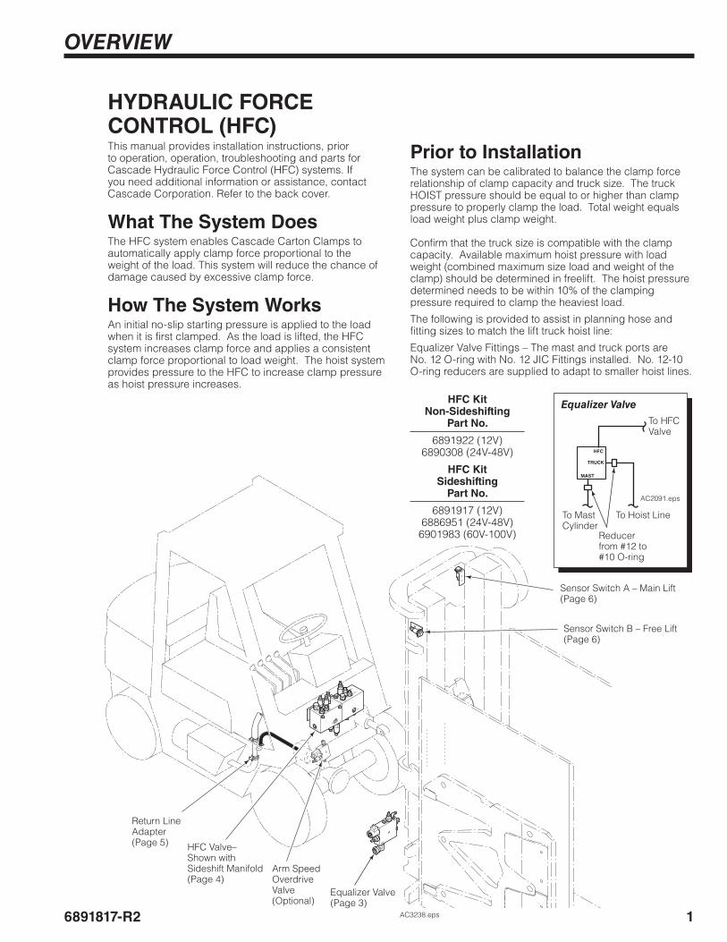
HYDRAULIC FORCE CONTROL (HFC)This manual provides installation instructions, prior to operation, operation, troubleshooting and parts for Cascade Hydraulic Force Control (HFC) systems. If you need additional information or assistance, contact Cascade Corporation. Refer to the back cover.
What The System DoesThe HFC system enables Cascade Carton Clamps to automatically apply clamp force proportional to the weight of the load. This system will reduce the chance of damage caused by excessive clamp force.
How The System WorksAn initial no-slip starting pressure is applied to the load when it is first clamped. As the load is lifted, the HFC system increases clamp force and applies a consistent clamp force proportional to load weight. The hoist system provides pressure to the HFC to increase clamp pressure as hoist pressure increases.
Return Line Adapter(Page 5) HFC Valve–
Shown with Sideshift Manifold(Page 4)
Equalizer Valve(Page 3)
Sensor Switch A – Main Lift(Page 6)
Prior to InstallationThe system can be calibrated to balance the clamp force relationship of clamp capacity and truck size. The truck HOIST pressure should be equal to or higher than clamp pressure to properly clamp the load. Total weight equals load weight plus clamp weight.
Confirm that the truck size is compatible with the clamp capacity. Available maximum hoist pressure with load weight (combined maximum size load and weight of the clamp) should be determined in freelift. The hoist pressure determined needs to be within 10% of the clamping pressure required to clamp the heaviest load.
The following is provided to assist in planning hose and fitting sizes to match the lift truck hoist line:
Equalizer Valve Fittings – The mast and truck ports are No. 12 O-ring with No. 12 JIC Fittings installed. No. 12-10 O-ring reducers are supplied to adapt to smaller hoist lines.
HFC KitNon-Sideshifting
Part No.
6891922 (12V)6890308 (24V-48V)
HFC Kit Sideshifting
Part No.
6891917 (12V)6886951 (24V-48V)
6901983 (60V-100V)
HFC
MAST
TRUCK
AC2091.eps
To HFC Valve
To Hoist Line
Reducerfrom #12 to #10 O-ring
To Mast Cylinder
Equalizer Valve
Sensor Switch B – Free Lift(Page 6)
Arm Speed Overdrive Valve (Optional)
INSTALLATION
2 6891817-R2
CL6387.eps
CL6386.eps
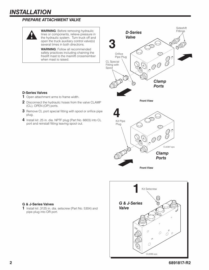
PREPARE ATTACHMENT VALVE
WARNING: Before removing hydraulic lines or components, relieve pressure in the hydraulic system. Turn truck off and open the truck auxiliary control valve(s) several times in both directions.
WARNING: Follow all recommended safety practices including chaining the freelift mast to the mainlift crossmember when mast is raised.
D-Series Valves 1 Open attachment arms to frame width.
2 Disconnect the hydraulic hoses from the valve CLAMP (CL), OPEN (OP) ports.
3 Remove CL port special fitting with spool or orifice pipe plug.
4 Install kit .25 in. dia. NPTF plug (Part No. 6603) into CL port and reinstall fitting leaving spool out.
4
1
3CL Special Fitting with Spool
Orifice Pipe Plug
Sideshift Fittings
Kit Setscrew
Kit Pipe Plug
Front View
Front View
Clamp Ports
Clamp Ports
G & J-Series Valve
D-Series Valve
G & J-Series Valves 1 Install kit .3125 in. dia. setscrew (Part No. 5304) and
pipe plug into OR port.
INSTALLATION
36891817-R2
AC3103.eps
HFC
MAST
TRUCK
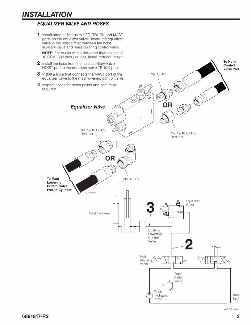
1 Install adapter fittings to HFC, TRUCK and MAST ports on the equalizer valve. Install the equalizer valve in the hoist circuit between the hoist auxiliary valve and mast lowering control valve.
NOTE: For trucks with a delivered flow volume of 18 GPM (68 L/min.) or less, install reducer fittings.
2 Install the hose from the hoist auxiliary valve HOIST port to the equalizer valve TRUCK port.
3 Install a hose that connects the MAST port of the equalizer valve to the mast lowering control valve.
4 Inspect hoses for pinch points and secure as required.
2
3Equalizer Valve
TruckHydraulicPump
TruckReliefValve
TruckTank
Mast Cylinders
HoistAuxiliaryValve
EQUALIZER VALVE AND HOSES
Existing Lowering Control Valve
HFC
MAST
TRU
CK
V6
V5
AC3102.eps
Equalizer Valve
To Mast Lowering Control Valve Freelift Cylinder
To Hoist Control Valve Port
OR
OR
No. 12-10 O-Ring Reducer
No. 12-10 O-Ring Reducer
No. 12 JIC
No. 12 JIC
INSTALLATION
4 6891817-R2
AC3106.eps
OP1 CL1 H T
OP2 CL2
HFC
MAST
TRUCK
CL
OPSS
SS OUT
SS INH
HFC VALVE AND HOSES
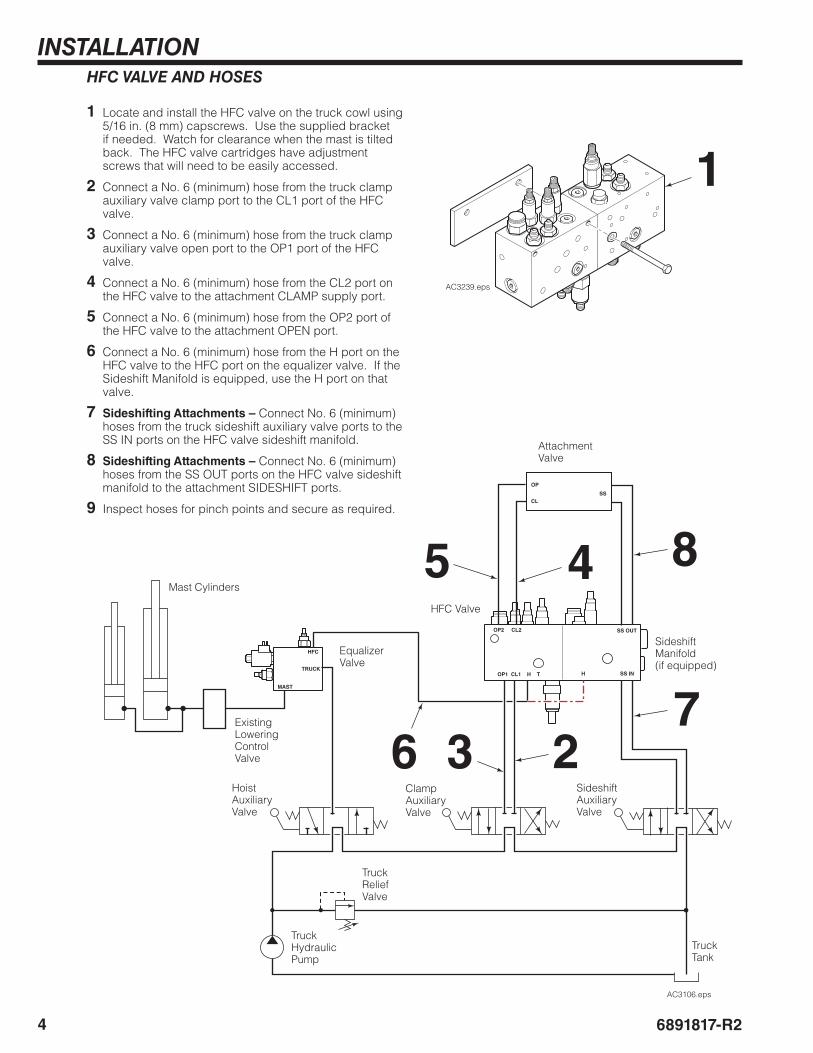
1 Locate and install the HFC valve on the truck cowl using 5/16 in. (8 mm) capscrews. Use the supplied bracket if needed. Watch for clearance when the mast is tilted back. The HFC valve cartridges have adjustment screws that will need to be easily accessed.
2 Connect a No. 6 (minimum) hose from the truck clamp auxiliary valve clamp port to the CL1 port of the HFC valve.
3 Connect a No. 6 (minimum) hose from the truck clamp auxiliary valve open port to the OP1 port of the HFC valve.
4 Connect a No. 6 (minimum) hose from the CL2 port on the HFC valve to the attachment CLAMP supply port.
5 Connect a No. 6 (minimum) hose from the OP2 port of the HFC valve to the attachment OPEN port.
6 Connect a No. 6 (minimum) hose from the H port on the HFC valve to the HFC port on the equalizer valve. If the Sideshift Manifold is equipped, use the H port on that valve.
7 Sideshifting Attachments – Connect No. 6 (minimum) hoses from the truck sideshift auxiliary valve ports to the SS IN ports on the HFC valve sideshift manifold.
8 Sideshifting Attachments – Connect No. 6 (minimum) hoses from the SS OUT ports on the HFC valve sideshift manifold to the attachment SIDESHIFT ports.
9 Inspect hoses for pinch points and secure as required.
Equalizer Valve
TruckHydraulicPump
TruckReliefValve
TruckTank
Mast Cylinders
HFC Valve
Attachment Valve
HoistAuxiliaryValve
SideshiftAuxiliaryValve
Existing Lowering Control Valve
4
36
5
2
1
ClampAuxiliaryValve
7
8
Sideshift Manifold(if equipped)
AC3239.eps
INSTALLATION
56891817-R2
AC3107.eps
OP1 CL1 H T TH
OP2 CL2
CL
OP
SS OUT
SS IN
SS
RETURN LINE ADAPTER
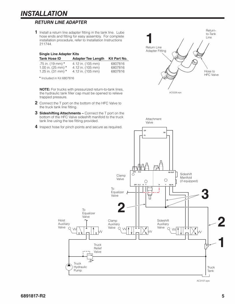
1 Install a return line adapter fitting in the tank line. Lube hose ends and fitting for easy assembly. For complete installation procedure, refer to Installation Instructions 211744.
To Equalizer Valve
To Equalizer Valve
TruckHydraulicPump
TruckReliefValve
TruckTank
Clamp Valve
Attachment Valve
HoistAuxiliaryValve
ClampAuxiliaryValve
AC0226.eps
Return Line Adapter Fitting
Return-to-Tank Line
Hose to HFC Valve
1
1
2
NOTE: For trucks with pressurized return-to-tank lines, the hydraulic tank filler cap must be opened to relieve trapped pressure.
2 Connect the T port on the bottom of the HFC Valve to the truck tank line fitting.
3 Sideshifting Attachments – Connect the T port on the bottom of the HFC Valve sideshift manifold to the truck tank line using the tee fitting provided.
4 Inspect hose for pinch points and secure as required.
3
Sideshift Manifold(if equipped)
Sideshift AuxiliaryValve
Single Line Adapter KitsTank Hose ID Adapter Tee Length Kit Part No..75 in. (19 mm) *1.00 in. (25 mm) *1.25 in. (31 mm) *
4.12 in. (105 mm)4.12 in. (105 mm)4.12 in. (105 mm)
6807816 6807816 6807816
* Included in Kit 6807816
2
INSTALLATION
6 6891817-R2
AC3155.eps
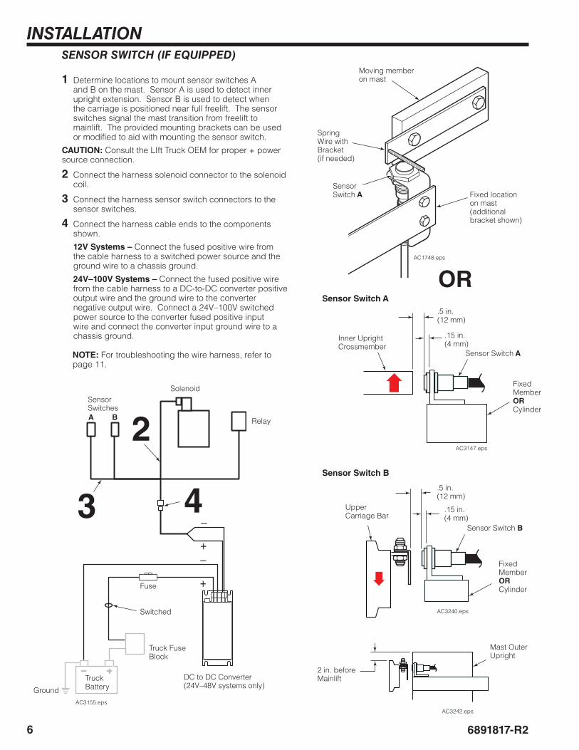
SENSOR SWITCH (IF EQUIPPED)
1 Determine locations to mount sensor switches A and B on the mast. Sensor A is used to detect inner upright extension. Sensor B is used to detect when the carriage is positioned near full freelift. The sensor switches signal the mast transition from freelift to mainlift. The provided mounting brackets can be used or modified to aid with mounting the sensor switch.
CAUTION: Consult the LIft Truck OEM for proper + power source connection.
2 Connect the harness solenoid connector to the solenoid coil.
3 Connect the harness sensor switch connectors to the sensor switches.
4 Connect the harness cable ends to the components shown.
12V Systems – Connect the fused positive wire from the cable harness to a switched power source and the ground wire to a chassis ground.
24V–100V Systems – Connect the fused positive wire from the cable harness to a DC-to-DC converter positive output wire and the ground wire to the converter negative output wire. Connect a 24V–100V switched power source to the converter fused positive input wire and connect the converter input ground wire to a chassis ground.
NOTE: For troubleshooting the wire harness, refer to page 11.
AC1748.eps
Moving member on mast
Fixed location on mast(additional bracket shown)
Spring Wire with Bracket(if needed)
Sensor Switch A
OR
SolenoidSensor Switches
Relay
Truck Fuse Block
Truck Battery
Fuse
4
2
3
DC to DC Converter(24V–48V systems only)
Ground
Switched
A B
AC3147.eps
Inner Upright Crossmember
Fixed Member ORCylinder
Sensor Switch A
.5 in.(12 mm)
.15 in.(4 mm)
Sensor Switch A
Upper Carriage Bar
Fixed Member ORCylinder
Sensor Switch B
.5 in.(12 mm)
.15 in.(4 mm)
Sensor Switch B
2 in. before Mainlift
Mast Outer Upright
AC3240.eps
AC3242.eps
INSTALLATION
76891817-R2
HFC
MAST
TRU
CK
V6
V5
AC3112.eps
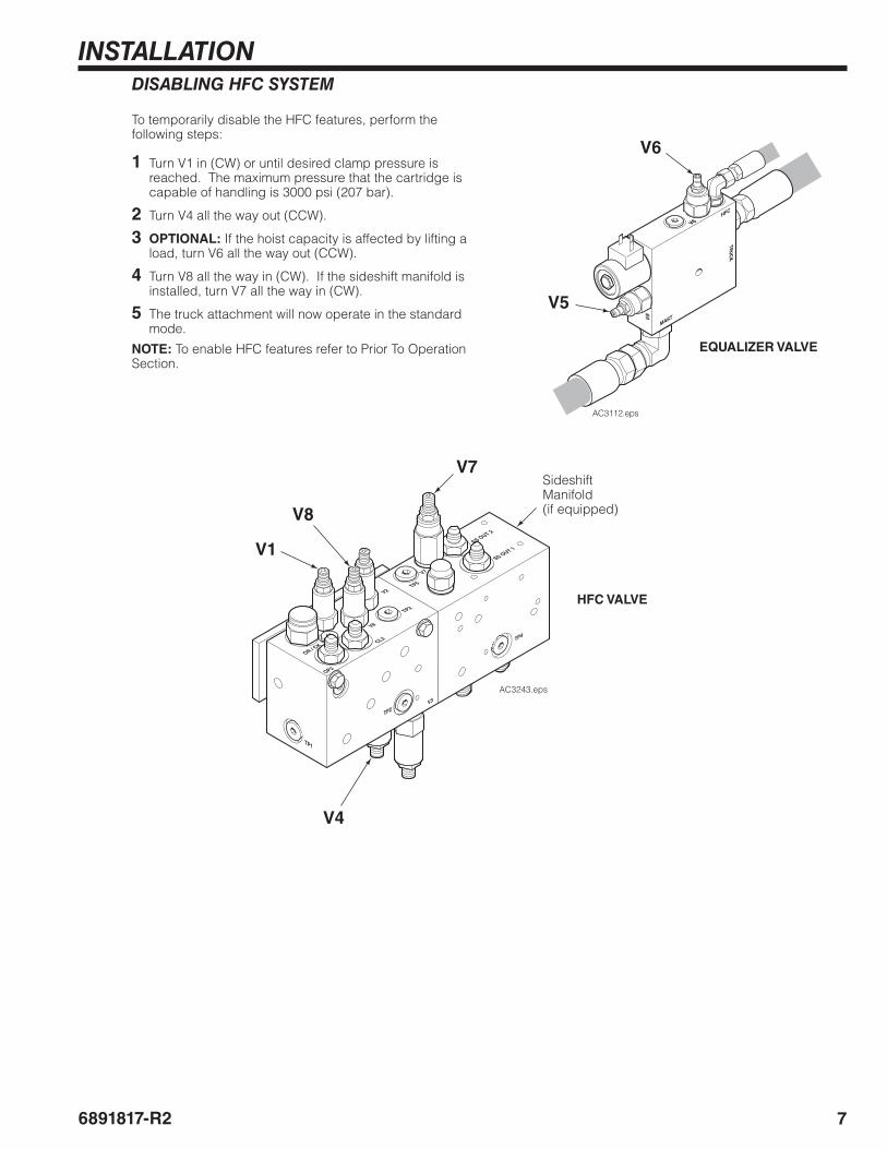
DISABLING HFC SYSTEM
To temporarily disable the HFC features, perform the following steps:
1 Turn V1 in (CW) or until desired clamp pressure is reached. The maximum pressure that the cartridge is capable of handling is 3000 psi (207 bar).
2 Turn V4 all the way out (CCW).
3 OPTIONAL: If the hoist capacity is affected by lifting a load, turn V6 all the way out (CCW).
4 Turn V8 all the way in (CW). If the sideshift manifold is installed, turn V7 all the way in (CW).
5 The truck attachment will now operate in the standard mode.
NOTE: To enable HFC features refer to Prior To Operation Section.
V1
V4
HFC VALVE
EQUALIZER VALVE
V5
V8
V7Sideshift Manifold(if equipped)
V6
V8
AC3243.eps
TP1
TP2
V2
TP4
V7
OR / CK
TP5
TP3
SS OUT 2
SS OUT 1
CL2
OP2
V3
8 6891817-R2
SETUP
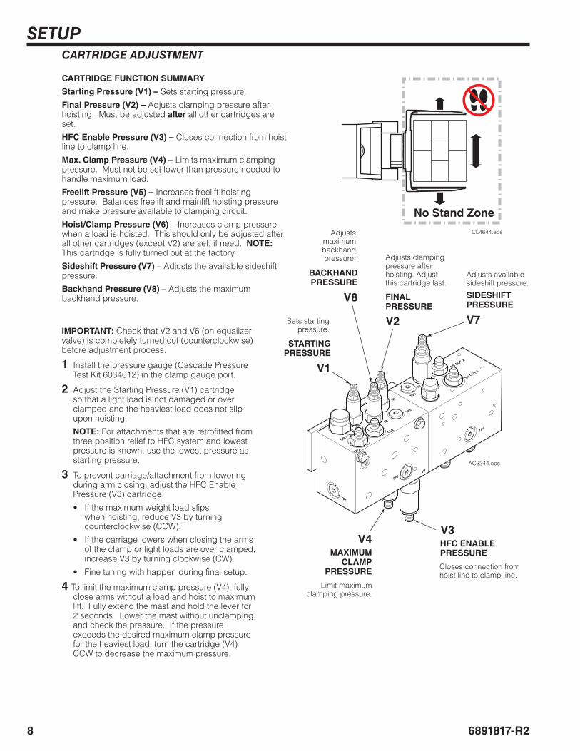
CARTRIDGE FUNCTION SUMMARY
Starting Pressure (V1) – Sets starting pressure.
Final Pressure (V2) – Adjusts clamping pressure after hoisting. Must be adjusted after all other cartridges are set.
HFC Enable Pressure (V3) – Closes connection from hoist line to clamp line.
Max. Clamp Pressure (V4) – Limits maximum clamping pressure. Must not be set lower than pressure needed to handle maximum load.
Freelift Pressure (V5) – Increases freelift hoisting pressure. Balances freelift and mainlift hoisting pressure and make pressure available to clamping circuit.
Hoist/Clamp Pressure (V6) – Increases clamp pressure when a load is hoisted. This should only be adjusted after all other cartridges (except V2) are set, if need. NOTE: This cartridge is fully turned out at the factory.
Sideshift Pressure (V7) – Adjusts the available sideshift pressure.
Backhand Pressure (V8) – Adjusts the maximum backhand pressure.
V1
V3
V2
V4
STARTING PRESSURE
FINAL PRESSURE
HFC ENABLE PRESSUREMAXIMUM
CLAMP PRESSURE
CARTRIDGE ADJUSTMENT
Adjusts clamping pressure after hoisting. Adjust this cartridge last.
Sets starting pressure.
Closes connection from hoist line to clamp line.
Limit maximum clamping pressure.
IMPORTANT: Check that V2 and V6 (on equalizer valve) is completely turned out (counterclockwise) before adjustment process.
1 Install the pressure gauge (Cascade Pressure Test Kit 6034612) in the clamp gauge port.
2 Adjust the Starting Pressure (V1) cartridge so that a light load is not damaged or over clamped and the heaviest load does not slip upon hoisting.
NOTE: For attachments that are retrofitted from three position relief to HFC system and lowest pressure is known, use the lowest pressure as starting pressure.
3 To prevent carriage/attachment from lowering during arm closing, adjust the HFC Enable Pressure (V3) cartridge.
• If the maximum weight load slips when hoisting, reduce V3 by turning counterclockwise (CCW).
• If the carriage lowers when closing the arms of the clamp or light loads are over clamped, increase V3 by turning clockwise (CW).
• Fine tuning with happen during final setup.
4 To limit the maximum clamp pressure (V4), fully close arms without a load and hoist to maximum lift. Fully extend the mast and hold the lever for 2 seconds. Lower the mast without unclamping and check the pressure. If the pressure exceeds the desired maximum clamp pressure for the heaviest load, turn the cartridge (V4) CCW to decrease the maximum pressure.
No Stand Zone
CL4644.eps
V8
BACKHAND PRESSURE
Adjusts maximum backhand pressure.
V7
Adjusts available sideshift pressure.
SIDESHIFT PRESSURE
V8
TP1
TP2
V2
TP4
V7
OR / CK
TP5
TP3
SS OUT 2
SS OUT 1
CL2
OP2
V3
AC3244.eps
96891817-R2
SETUP
HFC
MAST
TRU
CK
V6
V5
AC3112.eps
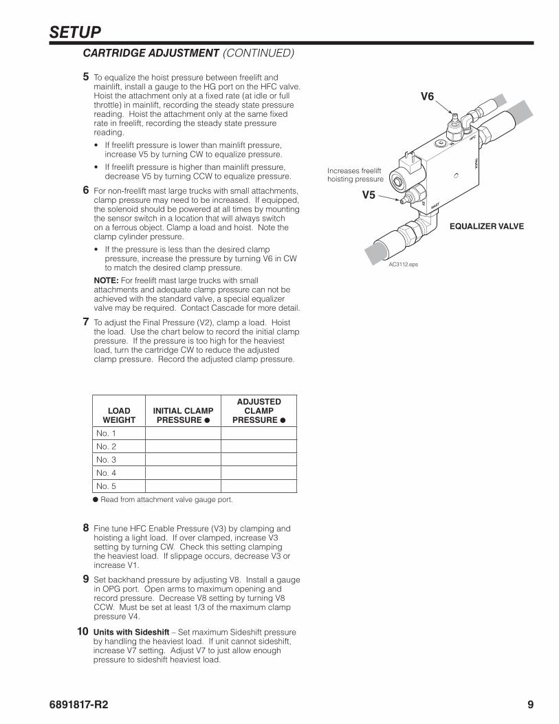
CARTRIDGE ADJUSTMENT (CONTINUED)
5 To equalize the hoist pressure between freelift and mainlift, install a gauge to the HG port on the HFC valve. Hoist the attachment only at a fixed rate (at idle or full throttle) in mainlift, recording the steady state pressure reading. Hoist the attachment only at the same fixed rate in freelift, recording the steady state pressure reading.
• If freelift pressure is lower than mainlift pressure, increase V5 by turning CW to equalize pressure.
• If freelift pressure is higher than mainlift pressure, decrease V5 by turning CCW to equalize pressure.
6 For non-freelift mast large trucks with small attachments, clamp pressure may need to be increased. If equipped, the solenoid should be powered at all times by mounting the sensor switch in a location that will always switch on a ferrous object. Clamp a load and hoist. Note the clamp cylinder pressure.
• If the pressure is less than the desired clamp pressure, increase the pressure by turning V6 in CW to match the desired clamp pressure.
NOTE: For freelift mast large trucks with small attachments and adequate clamp pressure can not be achieved with the standard valve, a special equalizer valve may be required. Contact Cascade for more detail.
7 To adjust the Final Pressure (V2), clamp a load. Hoist the load. Use the chart below to record the initial clamp pressure. If the pressure is too high for the heaviest load, turn the cartridge CW to reduce the adjusted clamp pressure. Record the adjusted clamp pressure.
LOADWEIGHT
INITIAL CLAMP PRESSURE ●
ADJUSTED CLAMP
PRESSURE ●
No. 1
No. 2
No. 3
No. 4
No. 5
●Read from attachment valve gauge port.
Increases freelift hoisting pressure
EQUALIZER VALVE
V5
V6
8 Fine tune HFC Enable Pressure (V3) by clamping and hoisting a light load. If over clamped, increase V3 setting by turning CW. Check this setting clamping the heaviest load. If slippage occurs, decrease V3 or increase V1.
9 Set backhand pressure by adjusting V8. Install a gauge in OPG port. Open arms to maximum opening and record pressure. Decrease V8 setting by turning V8 CCW. Must be set at least 1/3 of the maximum clamp pressure V4.
10 Units with Sideshift – Set maximum Sideshift pressure by handling the heaviest load. If unit cannot sideshift, increase V7 setting. Adjust V7 to just allow enough pressure to sideshift heaviest load.
10 6891817-R2
OPERATION
CL0085.eps
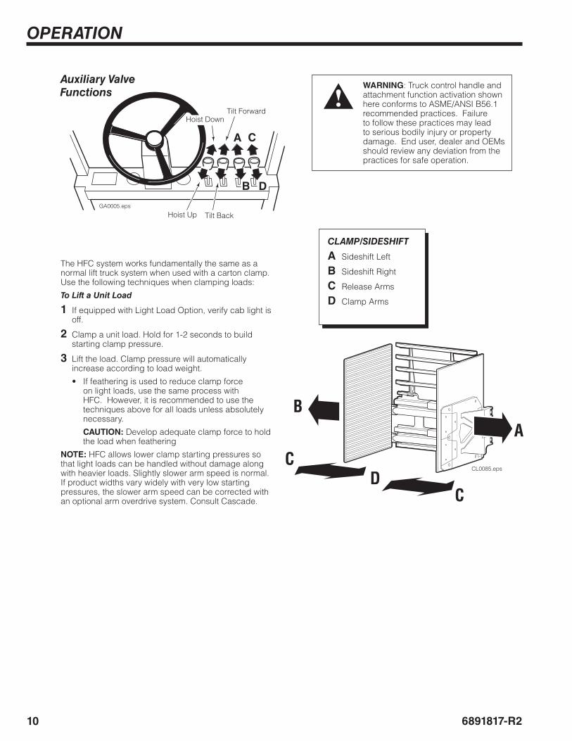
WARNING: Truck control handle and attachment function activation shown here conforms to ASME/ANSI B56.1 recommended practices. Failure to follow these practices may lead to serious bodily injury or property damage. End user, dealer and OEMs should review any deviation from the practices for safe operation.
B D
CA
GA0005.eps
Hoist Down
Hoist Up
Tilt Forward
Tilt Back
Auxiliary Valve Functions
CLAMP/SIDESHIFT
A Sideshift Left
B Sideshift Right
C Release Arms
D Clamp Arms
AB
C
CD
The HFC system works fundamentally the same as a normal lift truck system when used with a carton clamp. Use the following techniques when clamping loads:
To Lift a Unit Load
1 If equipped with Light Load Option, verify cab light is off.
2 Clamp a unit load. Hold for 1-2 seconds to build starting clamp pressure.
3 Lift the load. Clamp pressure will automatically increase according to load weight.
• If feathering is used to reduce clamp force on light loads, use the same process with HFC. However, it is recommended to use the techniques above for all loads unless absolutely necessary.
CAUTION: Develop adequate clamp force to hold the load when feathering
NOTE: HFC allows lower clamp starting pressures so that light loads can be handled without damage along with heavier loads. Slightly slower arm speed is normal. If product widths vary widely with very low starting pressures, the slower arm speed can be corrected with an optional arm overdrive system. Consult Cascade.
116891817-R2
TROUBLESHOOTING
AC3154.eps
3 1
4
3 1
4
B
A
2
2
1
2
308685
87
87A
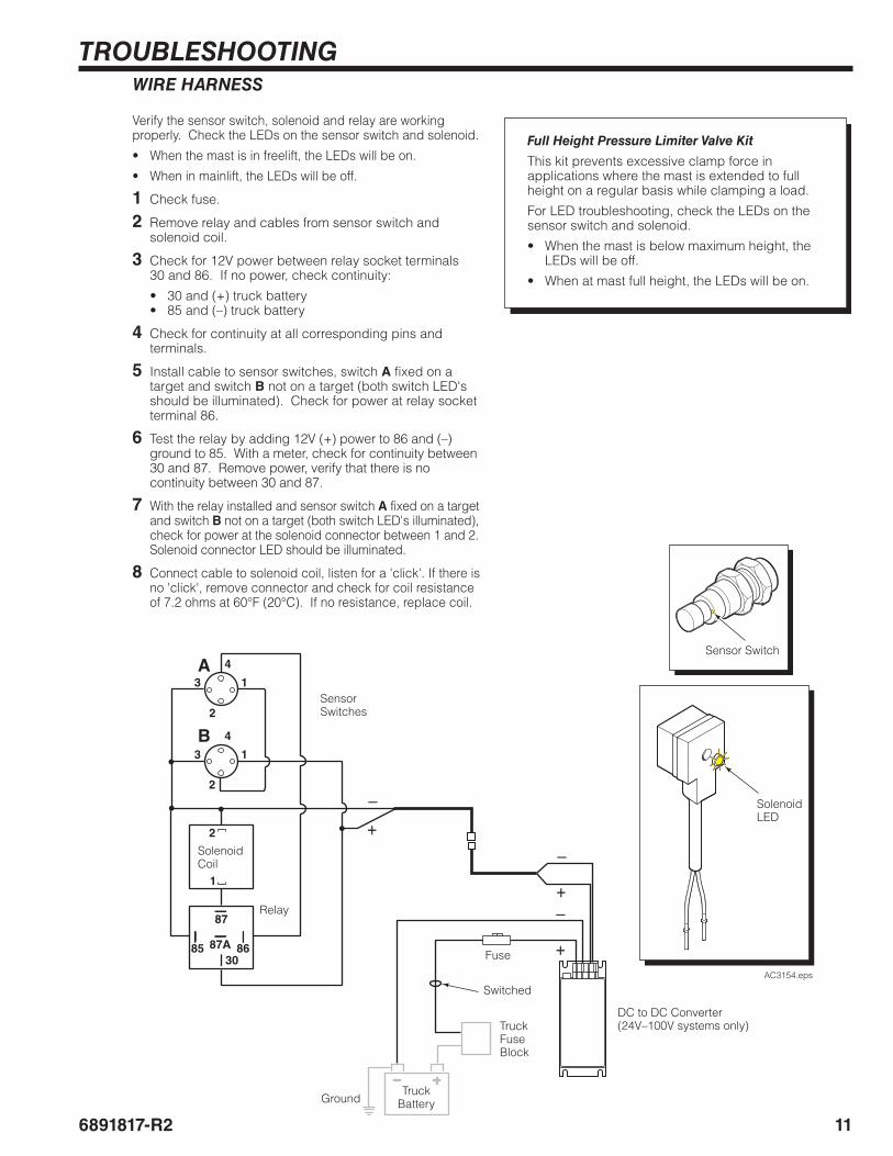
WIRE HARNESS
Verify the sensor switch, solenoid and relay are working properly. Check the LEDs on the sensor switch and solenoid.
• When the mast is in freelift, the LEDs will be on.
• When in mainlift, the LEDs will be off.
1 Check fuse.
2 Remove relay and cables from sensor switch and solenoid coil.
3 Check for 12V power between relay socket terminals 30 and 86. If no power, check continuity:
• 30 and (+) truck battery• 85 and (–) truck battery
4 Check for continuity at all corresponding pins and terminals.
5 Install cable to sensor switches, switch A fixed on a target and switch B not on a target (both switch LED's should be illuminated). Check for power at relay socket terminal 86.
6 Test the relay by adding 12V (+) power to 86 and (–) ground to 85. With a meter, check for continuity between 30 and 87. Remove power, verify that there is no continuity between 30 and 87.
7 With the relay installed and sensor switch A fixed on a target and switch B not on a target (both switch LED's illuminated), check for power at the solenoid connector between 1 and 2. Solenoid connector LED should be illuminated.
8 Connect cable to solenoid coil, listen for a 'click'. If there is no 'click', remove connector and check for coil resistance of 7.2 ohms at 60°F (20°C). If no resistance, replace coil.
Sensor Switches
Sensor Switch
Solenoid LED
Solenoid Coil
Relay
Truck Fuse Block
Switched
Ground
Fuse
Truck Battery
DC to DC Converter(24V–100V systems only)
Full Height Pressure Limiter Valve Kit
This kit prevents excessive clamp force in applications where the mast is extended to full height on a regular basis while clamping a load.
For LED troubleshooting, check the LEDs on the sensor switch and solenoid.
• When the mast is below maximum height, the LEDs will be off.
• When at mast full height, the LEDs will be on.
12 6891817-R2
TROUBLESHOOTING
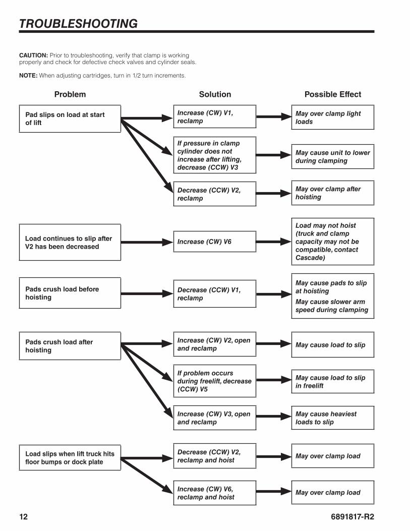
CAUTION: Prior to troubleshooting, verify that clamp is working properly and check for defective check valves and cylinder seals.
NOTE: When adjusting cartridges, turn in 1/2 turn increments.
Increase (CW) V1, reclamp
If pressure in clamp cylinder does not increase after lifting, decrease (CCW) V3
Decrease (CCW) V2, reclamp
Decrease (CCW) V1, reclamp
Increase (CW) V2, open and reclamp
If problem occurs during freelift, decrease (CCW) V5
Increase (CW) V3, open and reclamp
Decrease (CCW) V2, reclamp and hoist
Increase (CW) V6, reclamp and hoist
Pad slips on load at start of lift
Pads crush load before hoisting
Pads crush load after hoisting
Load slips when lift truck hits floor bumps or dock plate
May over clamp light loads
May cause unit to lower during clamping
May over clamp after hoisting
May cause pads to slip at hoisting
May cause slower arm speed during clamping
May cause load to slip
May cause load to slip in freelift
May cause heaviest loads to slip
May over clamp load
May over clamp load
Problem Solution Possible Effect
Increase (CW) V6Load continues to slip after V2 has been decreased
Load may not hoist (truck and clamp capacity may not be compatible, contact Cascade)
136891817-R2
TROUBLESHOOTING
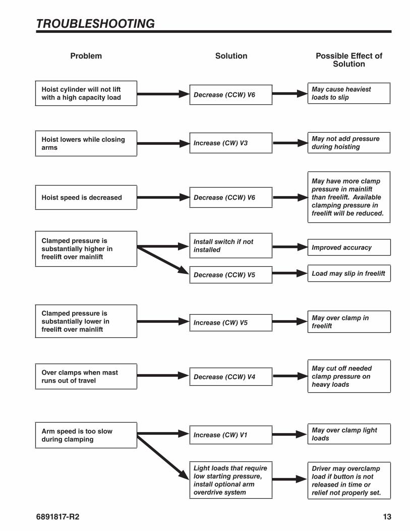
Install switch if not installed
Decrease (CCW) V5
Increase (CW) V5
Decrease (CCW) V4
Increase (CW) V1
Light loads that require low starting pressure, install optional arm overdrive system
Clamped pressure is substantially higher in freelift over mainlift
Clamped pressure is substantially lower in freelift over mainlift
Over clamps when mast runs out of travel
Arm speed is too slow during clamping
Improved accuracy
Load may slip in freelift
May over clamp in freelift
May cut off needed clamp pressure on heavy loads
May over clamp light loads
Driver may overclamp load if button is not released in time or relief not properly set.
Problem Solution Possible Effect of Solution
Increase (CW) V3
Decrease (CCW) V6
Hoist lowers while closing arms
Hoist speed is decreased
May not add pressure during hoisting
May have more clamp pressure in mainlift than freelift. Available clamping pressure in freelift will be reduced.
Decrease (CCW) V6Hoist cylinder will not lift with a high capacity load
May cause heaviest loads to slip
PARTS
14 6891817-R2
7
6
5
1
3
!0
¤
⁄
AC3236.eps
9
4
8
8
#
$
@
%
*
&
^
2
›
‹
fi
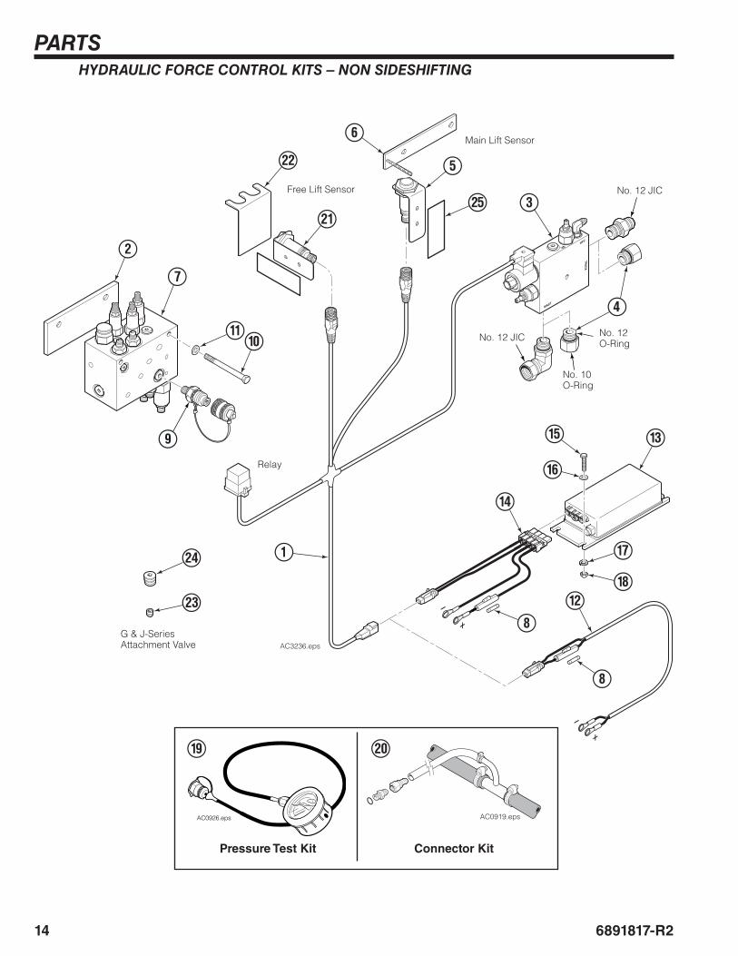
HYDRAULIC FORCE CONTROL KITS – NON SIDESHIFTING
Relay
AC0926.eps
Pressure Test Kit Connector Kit
AC0919.epsAC0919.eps
No. 12 JIC
No. 12 JIC
No. 10 O-Ring
No. 12 O-Ring
( )
G & J-Series Attachment Valve
Main Lift Sensor
Free Lift Sensor
PARTS
156891817-R2
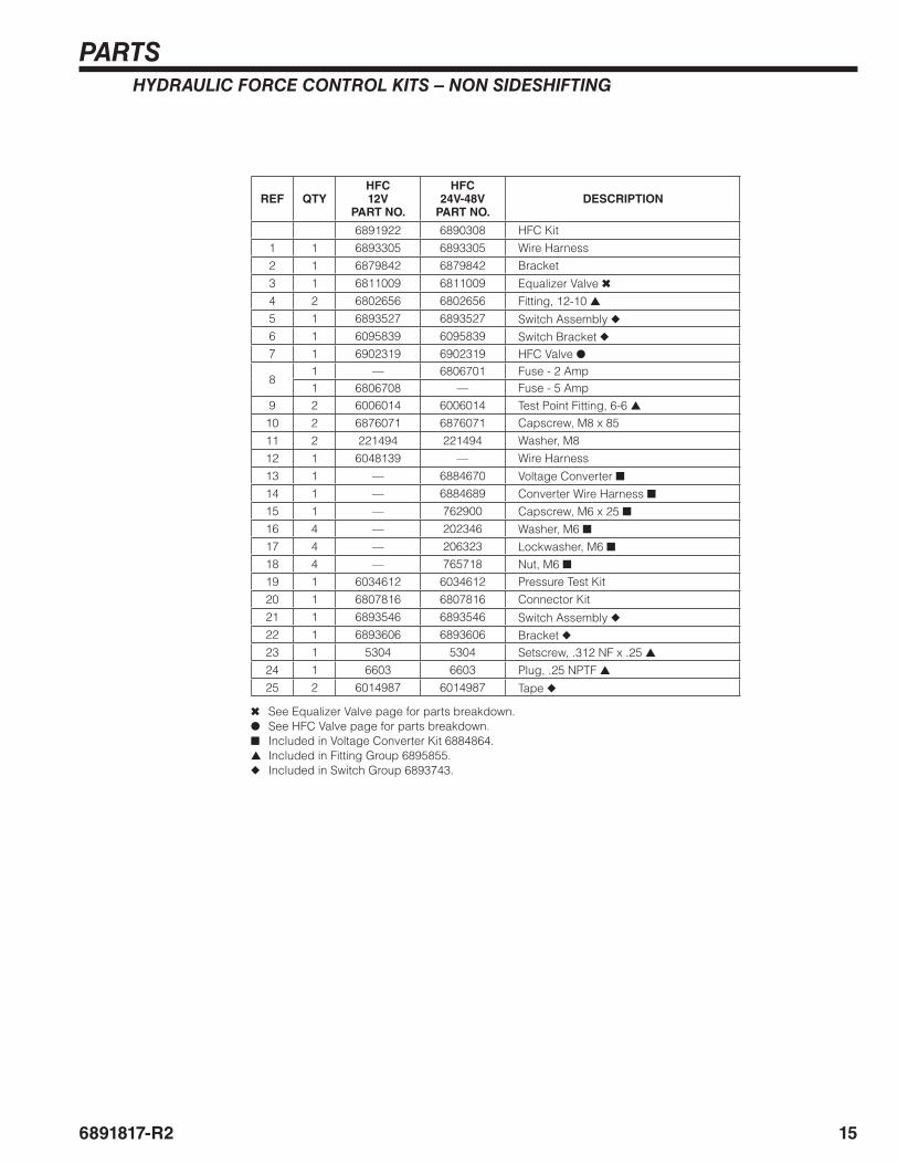
HYDRAULIC FORCE CONTROL KITS – NON SIDESHIFTING
REF QTYHFC12V
PART NO.
HFC24V-48V
PART NO.DESCRIPTION
6891922 6890308 HFC Kit1 1 6893305 6893305 Wire Harness2 1 6879842 6879842 Bracket3 1 6811009 6811009 Equalizer Valve ✖4 2 6802656 6802656 Fitting, 12-10 ▲5 1 6893527 6893527 Switch Assembly ◆6 1 6095839 6095839 Switch Bracket ◆7 1 6902319 6902319 HFC Valve ●
81 — 6806701 Fuse - 2 Amp1 6806708 — Fuse - 5 Amp
9 2 6006014 6006014 Test Point Fitting, 6-6 ▲10 2 6876071 6876071 Capscrew, M8 x 8511 2 221494 221494 Washer, M812 1 6048139 — Wire Harness13 1 — 6884670 Voltage Converter ■14 1 — 6884689 Converter Wire Harness ■15 1 — 762900 Capscrew, M6 x 25 ■16 4 — 202346 Washer, M6 ■17 4 — 206323 Lockwasher, M6 ■18 4 — 765718 Nut, M6 ■19 1 6034612 6034612 Pressure Test Kit20 1 6807816 6807816 Connector Kit21 1 6893546 6893546 Switch Assembly ◆22 1 6893606 6893606 Bracket ◆23 1 5304 5304 Setscrew, .312 NF x .25 ▲24 1 6603 6603 Plug, .25 NPTF ▲25 2 6014987 6014987 Tape ◆
✖ See Equalizer Valve page for parts breakdown.● See HFC Valve page for parts breakdown.■ Included in Voltage Converter Kit 6884864.▲ Included in Fitting Group 6895855.◆ Included in Switch Group 6893743.
PARTS
16 6891817-R2
7
6
5
1
3
!0
‡
fl
AC3237.eps
9
4
8
8
#
$
@
%
*
&
^
2
¤
⁄
›
‹
fi
°
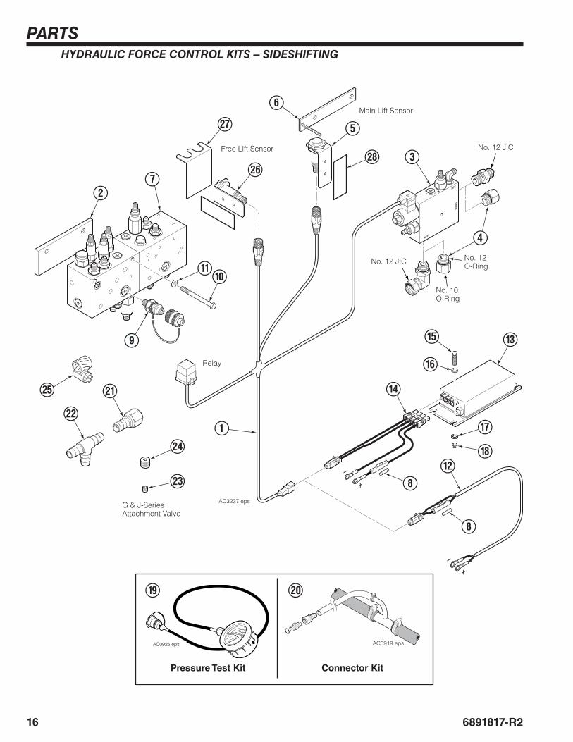
HYDRAULIC FORCE CONTROL KITS – SIDESHIFTING
Relay
AC0926.eps
Pressure Test Kit Connector Kit
AC0919.epsAC0919.eps
No. 12 JIC
No. 12 JIC
No. 10 O-Ring
No. 12 O-Ring
( )
G & J-Series Attachment Valve
Main Lift Sensor
Free Lift Sensor
PARTS
176891817-R2
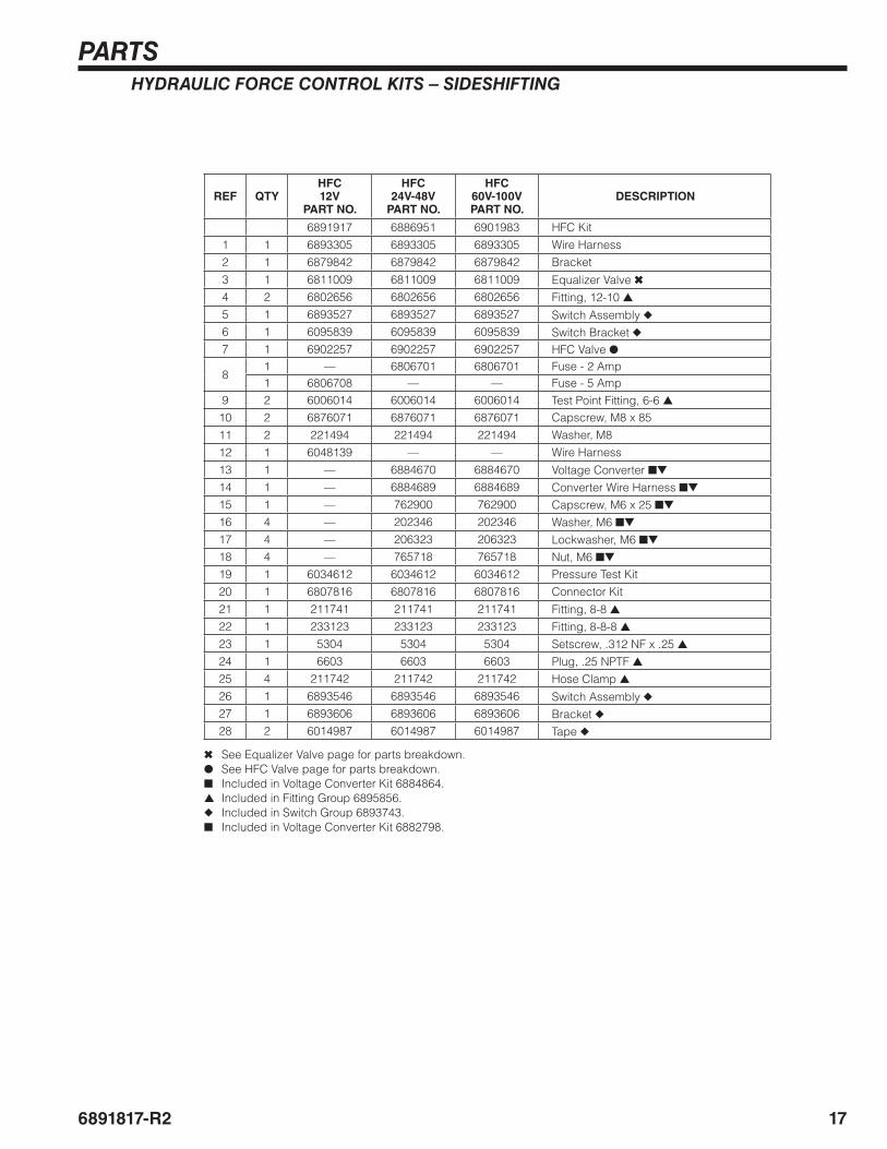
HYDRAULIC FORCE CONTROL KITS – SIDESHIFTING
REF QTYHFC12V
PART NO.
HFC24V-48V
PART NO.
HFC60V-100VPART NO.
DESCRIPTION
6891917 6886951 6901983 HFC Kit1 1 6893305 6893305 6893305 Wire Harness2 1 6879842 6879842 6879842 Bracket3 1 6811009 6811009 6811009 Equalizer Valve ✖4 2 6802656 6802656 6802656 Fitting, 12-10 ▲5 1 6893527 6893527 6893527 Switch Assembly ◆6 1 6095839 6095839 6095839 Switch Bracket ◆7 1 6902257 6902257 6902257 HFC Valve ●
81 — 6806701 6806701 Fuse - 2 Amp1 6806708 — — Fuse - 5 Amp
9 2 6006014 6006014 6006014 Test Point Fitting, 6-6 ▲10 2 6876071 6876071 6876071 Capscrew, M8 x 8511 2 221494 221494 221494 Washer, M812 1 6048139 — — Wire Harness13 1 — 6884670 6884670 Voltage Converter ■▼
14 1 — 6884689 6884689 Converter Wire Harness ■▼
15 1 — 762900 762900 Capscrew, M6 x 25 ■▼
16 4 — 202346 202346 Washer, M6 ■▼
17 4 — 206323 206323 Lockwasher, M6 ■▼
18 4 — 765718 765718 Nut, M6 ■▼
19 1 6034612 6034612 6034612 Pressure Test Kit20 1 6807816 6807816 6807816 Connector Kit21 1 211741 211741 211741 Fitting, 8-8 ▲22 1 233123 233123 233123 Fitting, 8-8-8 ▲23 1 5304 5304 5304 Setscrew, .312 NF x .25 ▲24 1 6603 6603 6603 Plug, .25 NPTF ▲25 4 211742 211742 211742 Hose Clamp ▲26 1 6893546 6893546 6893546 Switch Assembly ◆27 1 6893606 6893606 6893606 Bracket ◆28 2 6014987 6014987 6014987 Tape ◆
✖ See Equalizer Valve page for parts breakdown.● See HFC Valve page for parts breakdown.■ Included in Voltage Converter Kit 6884864.▲ Included in Fitting Group 6895856.◆ Included in Switch Group 6893743.■ Included in Voltage Converter Kit 6882798.
PARTS
18 6891817-R2
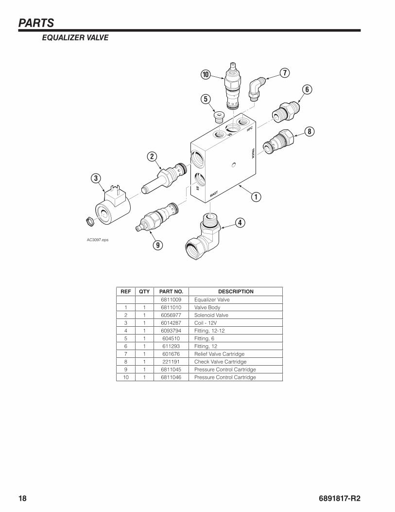
EQUALIZER VALVE
REF QTY PART NO. DESCRIPTION
6811009 Equalizer Valve1 1 6811010 Valve Body2 1 6056977 Solenoid Valve3 1 6014287 Coil - 12V4 1 6093794 Fitting, 12-125 1 604510 Fitting, 66 1 611293 Fitting, 127 1 601676 Relief Valve Cartridge8 1 221191 Check Valve Cartridge9 1 6811045 Pressure Control Cartridge10 1 6811046 Pressure Control Cartridge
HFC
MAST
TRU
CK
V6
V5
7
9
4
1
6
8
3
2
5
0
AC3097.eps
PARTS
196891817-R2
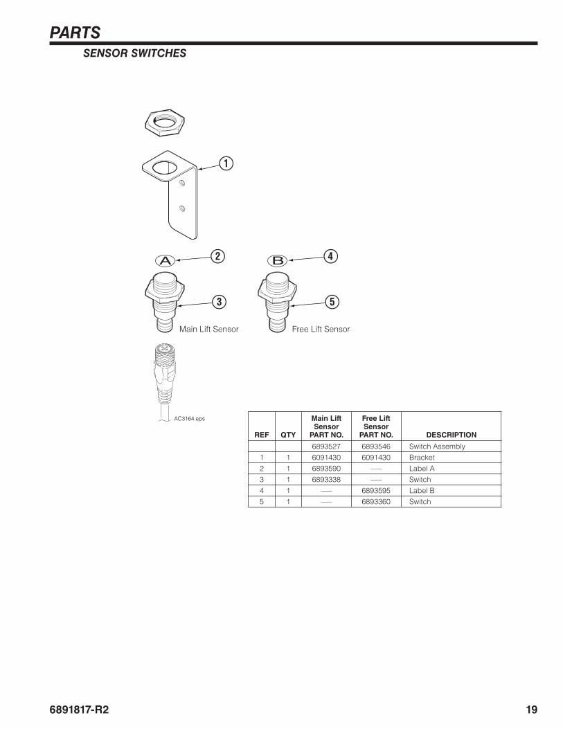
REF QTY
Main Lift Sensor
PART NO.
Free Lift Sensor
PART NO. DESCRIPTION
6893527 6893546 Switch Assembly1 1 6091430 6091430 Bracket2 1 6893590 ––– Label A3 1 6893338 ––– Switch4 1 ––– 6893595 Label B5 1 ––– 6893360 Switch
SENSOR SWITCHES
1
3
2
5
4
AC3164.eps
Main Lift Sensor Free Lift Sensor
PARTS
20 6891817-R2
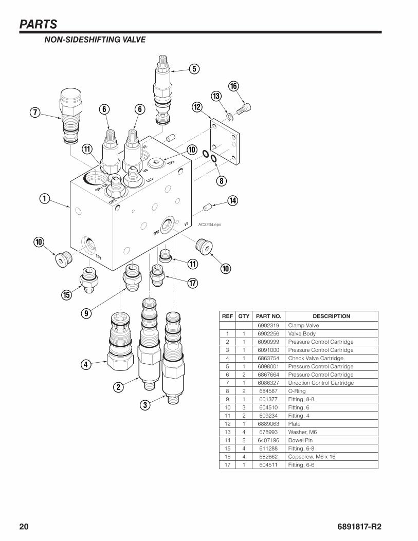
NON-SIDESHIFTING VALVE
V8
CL2
OP2
V3
TP1
V2
TP3
OR / CK
TP2
AC3234.eps
5
7 6 6
1
!
0
0
!
9
%
4
0
$
2
3
#@
^
8
&
REF QTY PART NO. DESCRIPTION
6902319 Clamp Valve1 1 6902256 Valve Body2 1 6090999 Pressure Control Cartridge3 1 6091000 Pressure Control Cartridge4 1 6863754 Check Valve Cartridge5 1 6098001 Pressure Control Cartridge6 2 6867664 Pressure Control Cartridge7 1 6086327 Direction Control Cartridge8 2 684587 O-Ring9 1 601377 Fitting, 8-8
10 3 604510 Fitting, 611 2 609234 Fitting, 412 1 6889063 Plate13 4 678993 Washer, M614 2 6407196 Dowel Pin15 4 611288 Fitting, 6-816 4 682662 Capscrew, M6 x 1617 1 604511 Fitting, 6-6
PARTS
216891817-R2
V8
CL2
OP2
V3
TP1
TP2
V2
TP4
V7
SS OUT 2
SS OUT 1
OR / CK
TP3
TP5
AC3235.eps
5
7 6 6
1
0
9
9
0
8
@
4
9
!
2
3
%
9
$
^
9
‹
¤
@
&(
)
8
*
9
#
0
⁄
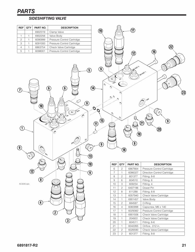
REF QTY PART NO. DESCRIPTION
6 2 6867664 Pressure Control Cartridge7 1 6086327 Direction Control Cartridge8 2 601377 Fitting, 8-89 6 604510 Fitting, 610 3 609234 Fitting, 411 2 6407196 Dowel Pin12 8 611288 Fitting, 6-813 1 6057940 Check Valve Cartridge14 1 6901457 Valve Body15 2 684587 O-Ring16 4 6060998 Capscrew, M6 x 14017 1 6029382 Pressure Control Cartridge18 1 6901506 Check Valve Cartridge19 1 204922 Check Valve Cartridge20 1 604511 Fitting, 6-621 1 6042265 Orifice, .012 in.22 2 6026590 Check Valve Cartridge23 2 601377 Fitting, 8-8
SIDESHIFTING VALVE
REF QTY PART NO. DESCRIPTION
6902319 Clamp Valve1 1 6902256 Valve Body2 1 6090999 Pressure Control Cartridge3 1 6091000 Pressure Control Cartridge4 1 6863754 Check Valve Cartridge5 1 6098001 Pressure Control Cartridge
22 6891817-R2
GLOSSARY
Clamp Pressure – Pressure set to clamp a load.
Starting Pressure (V1) – The minimum clamp pressure that will be applied, even on light loads.
Final Pressure (V2) – The final HFC adjusted clamp pressure applied when the load is hoisted.
HFC Enable Pressure (V3) – The hoist pressure to achieve prior to hoisting.
Maximum Clamp Pressure (V4) – The maximum pressure set to clamp a load.
Freelift Pressure (V5) – Pressure in the hoist line when the mast is in freelift state.
Hoist/Clamp Pressure (V6) – Increases clamp pressure when a load is hoisted.
Sideshift Pressure (V7) – Adjusts the available sideshift pressure.
Backhand Pressure (V8) – Adjusts the maximum backhand pressure.
Overdrive System – A system to aid with increasing arm speed and allows an attachment to have higher clamping pressure when breaking out rolls.
Total Load Weight – The sum of the load weight and clamp weight.

BLANK
c
Do you have questions you need answered right now? Call your nearest Cascade Service Department.Visit us online at www.cascorp.com
AMERICASCascade CorporationU.S. Headquarters2201 NE 201stFairview, OR 97024-9718Tel: 800-CASCADE (227-2233)Fax: 888-329-8207
Cascade Canada Inc.5570 Timberlea Blvd.Mississauga, OntarioCanada L4W-4M6Tel: 905-629-7777Fax: 905-629-7785
Cascade do BrasilPraça Salvador Rosa,131/141-Jordanópolis, São Bernardo do Campo - SPCEP 09891-430Tel: 55-13-2105-8800Fax: 55-13-2105-8899
EUROPE-AFRICACascade Italia S.R.L.European HeadquartersVia Dell’Artigianato 137030 Vago di Lavagno (VR) ItalyTel: 39-045-8989111Fax: 39-045-8989160
Cascade (Africa) Pty. Ltd.PO Box 625, Isando 160060A Steel RoadSparton, Kempton ParkSouth AfricaTel: 27-11-975-9240Fax: 27-11-394-1147
ASIA-PACIFICCascade Japan Ltd.2-23, 2-Chome,Kukuchi NishimachiAmagasaki, Hyogo Japan, 661-0978Tel: 81-6-6420-9771Fax: 81-6-6420-9777
Cascade Korea121B 9L Namdong Ind. Complex, 691-8 Gojan-DongNamdong-KuInchon, KoreaTel: +82-32-821-2051Fax: +82-32-821-2055
Cascade-XiamenNo. 668 Yangguang Rd. Xinyang Industrial ZoneHaicang, Xiamen CityFujian ProvinceP.R. China 361026Tel: 86-592-651-2500Fax: 86-592-651-2571
Cascade India Material Handling Private LimitedOffice No.21, 3rd Floor, Lokmanya House, Plot No.44, Sr. No. 89/90, CTS No.950, Lokmanya Colony, Paud Rd., Kothrud, Pune-411038 Phone : +91 955 250 3060
Cascade Australia Pty. Ltd.1445 Ipswich RoadRocklea, QLD 4107AustraliaTel: 1-800-227-223Fax: +61 7 3373-7333
Cascade New Zealand15 Ra Ora DriveEast Tamaki, AucklandNew ZealandTel: +64-9-273-9136Fax: +64-9-273-9137
Sunstream IndustriesPte. Ltd.18 Tuas South Street 5Singapore 637796Tel: +65-6795-7555Fax: +65-6863-1368
© Cascade Corporation 2018 02-2018 Part Number 6891817-R2