Embed Size (px)
Citation preview

HYDRAULIC FILTRATIONPRODUCTS
TO PERFORMPASSION
SPIN-ON FILTERS

1
A WORLDWIDE LEADER IN THE FIELD OF HYDRAULIC FILTRATION EQUIPMENT.
Our company started life in 1964, when Bruno Pasotto decided to attempt to cater for the requests of a market still to be fully explored, with the study, design, development, production and marketing of a vast range of fi lters for hydraulic equipment, capable of satisfying the needs of manufacturers in all sectors.The quality of our products, our extreme competitiveness compared with major international producers and our constant activities of research, design and development has made us a worldwide leader in the fi eld of hydraulic circuit fi ltering.Present for over 50 years in the market, we have played a truly decisive role in defi ning our sector, and by now we are a group capable of controlling our entire chain of production, monitoring all manufacturing processes to guarantee superior quality standards and to provide concrete solutions for the rapidly evolving needs of customers and the market.

Our customer-oriented philosophy, which enables us to satisfy all customer requests rapidly and with personalized products, makes us a dynamic and fl exible enterprise.The possibility of constantly controlling and monitoring the entire production process is essential to allow us to guarantee the quality of our products.
Our work is based on a skillful interaction between advanced technology and fi ne workmanship, customizing products according to specifi c market requests, focusing strongly on innovation and quality, and following every step in the manufacturing of both standard and special products, fully respecting customer expectations.
Introduction 2
LEADERMARKET

USA
CANADAUNITED KINGDOM
FRANCE
ITALY
GERMANY
INDIA
RUSSIA
P.R. CHINA
WORLDWIDE PRESENCE
8The Group boasts business branches
Our foreign Branches enable us to offer a diversified range of products that allow us to successfully face the aggressive challenge of international competition, and also to maintain a stable presence at a local level.
Introduction3

Introduction 4
TECHNOLOGY
Our constant quest for excellence in quality and technological innovation allows us to offer only the best solutions and services for applications in many fields, including general industry, test rigs, l u b r i c a t i o n , h e a v y e ng i n e e r i n g, r e n ewab l e energ ies, nava l engineering, offshore engineering, aviation systems, emerging technologies and mobile plant (i.e. tractors, excavators, concrete pumps, platforms).

Introduction5
AND PRODUCTION
Our high level of technological expertise means we can rely entirely on our own resources, without resorting to external providers. This in turn enables us to satisfy a growing number of customer requests, also exploiting our constantly updated range of machines and equ ipmen t , f ea tu r i ng fu l ly-automated workstations capable of 24-hour production.

Flow rates up to 3000 l/min
Pressure up to 20 bar
Mounting:- In-Line- Tank top- In single and duplex designs
Flow rates up to 300 l/min
Pressure up to 80 bar
Mounting:- In-Line- Tank top
Flow rates up to 875 l/min
Mounting:- Tank immersed- In-Line- In tank with shut off valve- In tank with fl ooded suction
Flow rates up to 750 l/min
Pressure from 110 bar up to 560 bar
Mounting:- In-Line- Manifold- In single and duplex designs
Flow rates up to 3000 l/min
Pressure up to 80 bar
Mounting:- In-Line- Parallel manifold version- In single and duplex designs
LOW & MEDIUM PRESSURE FILTERS
HIGH PRESSURE FILTERS
SPIN-ON FILTERS
Flow rates up to 365 l/min
Pressure up to 35 bar
Mounting:- In-Line- Tank top
SUCTION FILTERS
RETURN FILTERS
RETURN /SUCTIONFILTERS
Introduction 6

Flow rates up to 125 l/minPressure from 320 bar up to 1000 bar
Mounting:- In-Line- Manifold- In single and duplex designs
Flow rates from 15 l/min up to 200 l/min
MOBILE FILTRATION UNITS
- Oil fi ller and air breather plugs- Optical and electrical level gauges- Pressure gauge valve selectors- Pipe fi xing brackets- Pressure gauges
POWER TRANSMISSIONPRODUCTS
TANKACCESSORIES
CONTAMINATION MONITORING PRODUCTS
STAINLESS STEEL HIGH PRESSURE FILTERS
- Aluminium bell-housings for motors from 0.12 kW to 400 kW- Couplings in Aluminium Cast Iron - Steel- Damping rings- Foot bracket- Aluminium tanks- Cleaning covers
- Online, in-line particle counters- Off-line bottle sampling products- Fully calibrated using relevant ISO standards- A wide range of variants to support fl uid types and communication protocols
PRODUCT RANGEMP Filtri can offer a vast and articulated range of products for the global market, suitable for all industrial sectors using hydraulic equipment.
This includes filters (suction, return, return/suction, spin-on, pressure, stainless steel pressure) and structural components (motor/pump bell-housings, transmission couplings, damping rings, foot brackets, aluminium tanks, cleaning covers).
We can provide all the skills and solutions required by the modern hydraulics industry to monitor contamination levels and other fl uid conditions.
Mobile fi ltration units and a full range of accessories allow us to supply everything necessary for a complete service in the hydraulic circuits.
Introduction7

COMPANY
PRODUCT RANGE
CONTAMINATION MANAGEMENT
FILTER SIZING
CORRECTIVE FACTOR
INTRODUCTION
1
6
11
22
24
page1
STR & MPA - MPM
SF2 250 - 350
SF2 500
CLOGGING INDICATORS
Submerged suction filter, with bypass or magnetic column
Semi-submerged positive head suction filter, low flow rate
Semi-submerged positive head suction filter, high flow rate
875 231
160 42
800 211
l/min gpmSUCTION FILTERS
31
39
47
57
page
up to Qmax
28
psi
MPFX
MPLX
MPTX
MFBX
MPF
MPT
MFB
MPH
MPI
FRI
RF2
CLOGGING INDICATORS
ACCESSORIES
Tank top semi-immersed filter, standard filter element disassembly
Tank top semi-immersed filter, standard filter element disassembly
Tank top semi-immersed filter, easy filter element disassembly
Bowl assembly
Tank top semi-immersed filter, standard filter element disassembly
Tank top semi-immersed filter, easy filter element disassembly
Bowl assembly
Tank top semi-immersed filter, standard filter element disassembly
Tank top semi-immersed filter, standard filter element disassembly
Tank top semi-immersed filter, easy filter element disassembly, it can be used also as in-line filter
Semi-immersed under-head filter, easy filter element disassembly
750 198
1800 476
300 79
500 132
750 198
300 79
500 132
3000 793
3000 793
1500 396
350 92
8 116
10 145
8 116
8 116
8 116
8 116
8 116
10 145
10 145
20 290
20 290
l/min gpmRETURN FILTERS
63
91
99
117
125
153
171
179
203
215
231
238
248
page
up to Pmax up to Qmax
60 bar
psi
MRSX
LMP 124 MULTIPORT
CLOGGING INDICATORS
Unique TANK TOP filter for mobile machinery, with combined filtration on
return and suction to the inlet at the hydrostatic transmissions in closed circuit
Unique IN-LINE filter for mobile machinery, with combined filtration on return
and suction to the inlet at the hydrostatic transmissions in closed circuit
300 79
200 53
10 145
80 1160
l/min gpmRETURN / SUCTION FILTERS
253
265
273
page
up to Pmax up to Qmax
250 bar
psi
MPS
MSH
CLOGGING INDICATORS
Low pressure filter, available with single cartridge (CS) for in-line or flange
mounting or with two cartridge on the same axis on the opposite sides
In-line low and medium pressure filter available with single cartridge (CH)
365 96
195 52
12 174
35 508
l/min gpmSPIN-ON FILTERS
289
305
311
page
up to Pmax up to Qmax
286 bar
HYDRAULIC FILTRATION PRODUCTS
Introduction 8
INDEX
QUICK REFERENCE GUIDE
CLOGGING INDICATORS
639
page636
psi
FMP 039
FMP
FHP
FMM
FHA 051
FHM
FHB
FHF 325
FHD
CLOGGING INDICATORS
Filter high pressure, low flow rate applications
Filter high pressure, high flow rate applications
Typical high pressure filter for mobile applications, high flow rate
Typical high pressure filter for mobile applications, low flow rate
Filter optimized for use in high pressure operating systems, low flow rate
High pressure filter with intermediate manifold construction
High pressure for block mounting
In-line manifold top mounting
In-line duplex high pressure filter
80 21
475 125
750 198
250 66
140 37
450 119
485 128
500 132
345 91
110 1595
320 4641
420 6092
420 6092
560 8122
320 4641
320 4641
350 5076
350 5076
l/min gpmHIGH PRESSURE FILTERS
455
463
475
493
503
511
529
543
553
566
page
up to Pmax up to Qmax
452 bar
psi l/min gpm
up to Qmax
FZP
FZH
FZX
FZM
FZB
FZD
CLOGGING INDICATORS
In-line pressure filter with threaded mount
In-line pressure filter with threaded mount for higher pressure
In-line pressure filter with threaded mount up to 1000 bar
Manifold top mounting
Manifold side mounting
Duplex pressure filter for continuous operation requirements
420 6092
700 10153
1000 14504
320 4641
320 4641
350 5076
STAINLESS STEEL HIGH PRESSURE FILTERS
577
587
597
605
613
621
631
page
up to Pmax
574 bar
150 40
50 13
10 3
70 18
75 20
90 24
up to Pmax up to Qmax
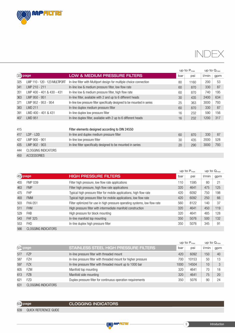
LMP 110 - 120 - 123 MULTIPORT
LMP 210 - 211
LMP 400 - 401 & 430 - 431
LMP 950 - 951
LMP 952 - 953 - 954
LMD 211
LMD 400 - 401 & 431
LMD 951
In-line filter with Multiport design for multiple choice connection
In-line low & medium pressure filter, low flow rate
In-line low & medium pressure filter, high flow rate
In-line filter, available with 2 and up to 6 different heads
In-line low pressure filter specifically designed to be mounted in series
In-line duplex medium pressure filter
In-line duplex low pressure filter
In-line duplex filter, available with 2 up to 6 different heads
200 53
330 87
740 195
2400 634
3000 793
330 87
590 156
1200 317
80 1160
60 870
60 870
30 435
25 363
60 870
16 232
16 232
LDP - LDD
LMP 900 - 901
LMP 902 - 903
Filter elements designed according to DIN 24550
In-line and duplex medium pressure filter
In-line low pressure filter
In-line filter specifically designed to be mounted in series
330 87
2000 528
3000 793
60 870
30 435
20 290
psi l/min gpmLOW & MEDIUM PRESSURE FILTERS
325
341
351
363
371
383
391
407
415
417
427
435
CLOGGING INDICATORS
ACCESSORIES
444
450
page322 bar
Introduction9

Introduction 10
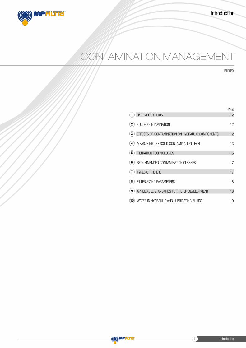
HYDRAULIC FLUIDS
FLUIDS CONTAMINATION
EFFECTS OF CONTAMINATION ON HYDRAULIC COMPONENTS
MEASURING THE SOLID CONTAMINATION LEVEL
FILTRATION TECHNOLOGIES
RECOMMENDED CONTAMINATION CLASSES
TYPES OF FILTERS
FILTER SIZING PARAMETERS
APPLICABLE STANDARDS FOR FILTER DEVELOPMENT
WATER IN HYDRAULIC AND LUBRICATING FLUIDS
12
12
12
13
16
17
17
18
18
19
Page
CONTAMINATION MANAGEMENTINDEX
Introduction
1
2
3
4
5
6
7
8
9
10
Introduction11

CONTAMINATION MANAGEMENT
HYDRAULIC FLUIDS
The fl uid is the vector that transmits power, energy within an oleodynamic circuit.In addition to transmitting energy through the circuit, it also performs additional functions such as lubrication, protection and cooling of the surfaces.The classifi cation of fl uids used in hydraulic systems is coded in many regulatory references, different Standards.
The most popular classifi cation criterion divides them into the following families:- MINERAL OILS Commonly used oil deriving fl uids.
- FIRE RESISTANT FLUIDS Fluids with intrinsic characteristics of incombustibility or high fl ash point.
- SYNTHETIC FLUIDS Modifi ed chemical products to obtain specifi c optimized features.
- ECOLOGICAL FLUIDS Synthetic or vegetable origin fl uids with high biodegradability characteristics.
The choice of fl uid for an hydraulic system must take into account several parameters.These parameters can adversely affect the performance of an hydraulic system, causing delay in the controls, pump cavitation, excessive absorption, excessive temperature rise, effi ciency reduction, increased drainage, wear, jam/block or air intake in the plant.
The main properties that characterize hydraulic fl uids and affect their choice are:- DYNAMIC VISCOSITY It identifi es the fl uid’s resistance to sliding due to the impact of the particles forming it.
- CINEMATIC VISCOSITY It is a widespread formal dimension in the hydraulic fi eld. It is calculated with the ratio between the dynamic viscosity and the fluid density. Cinematic viscosity varies with temperature and pressure variations.
- VISCOSITY INDEX This value expresses the ability of a fluid to maintain viscosity when the temperature changes. A high viscosity index indicates the fluid’s ability to limit viscosity variations by varying the temperature.
- FILTERABILITY INDEX It is the value that indicates the ability of a fluid to cross the filter materials. A low fi lterability index could cause premature clogging of the fi lter material.
- WORKING TEMPERATURE Working temperature affects the fundamental characteristics of the fluid. As already seen, some fl uid characteristics, such as cinematic viscosity, vary with the temperature variation. When choosing a hydraulic oil, must therefore be taken into account of the environmental conditions in which the machine will operate.
- COMPRESSIBILITY MODULE Every fl uid subjected to a pressure contracts, increasing its density. The compressibility module identifies the increase in pressure required to cause a corresponding increase in density.
- HYDROLYTIC STABILITY It is the characteristic that prevents galvanic pairs that can cause wear in the plant/system.
- ANTIOXIDANT STABILITY AND WEAR PROTECTION These features translate into the capacity of a hydraulic oil to avoid corrosion of metal elements inside the system.
- HEAT TRANSFER CAPACITY It is the characteristic that indicates the capacity of hydraulic oil to exchange heat with the surfaces and then cool them.
FLUID CONTAMINATION
Whatever the nature and properties of fluids, they are inevitably subject to contamination. Fluid contamination can have two origins:
- INITIAL CONTAMINATION Caused by the introduction of contaminated fl uid into the circuit, or by incorrect storage, transport or transfer operations.
- PROGRESSIVE CONTAMINATION Caused by factors related to the operation of the system, such as metal surface wear, sealing wear, oxidation or degradation of the fluid, the introduction of contaminants during maintenance, corrosion due to chemical or electrochemical action between fluid and components, cavitation. The contamination of hydraulic systems can be of different nature:
- SOLID CONTAMINATION For example rust, slag, metal particles, fi bers, rubber particles, paint particles - or additives
- LIQUID CONTAMINATION For example, the presence of water due to condensation or external infi ltration or acids
- GASEOUS CONTAMINATION For example, the presence of air due to inadequate oil level in the tank, drainage in suction ducts, incorrect sizing of tubes or tanks.
EFFECTS OF CONTAMINATION ON HYDRAULIC COMPONENTS
Solid contamination is recognized as the main cause of malfunction, failure and early degradation in hydraulic systems. It is impossible to delete it completely, but it can be effectively controlled by appropriate devices.
Solid contamination mainly causes surface damage and component wear.
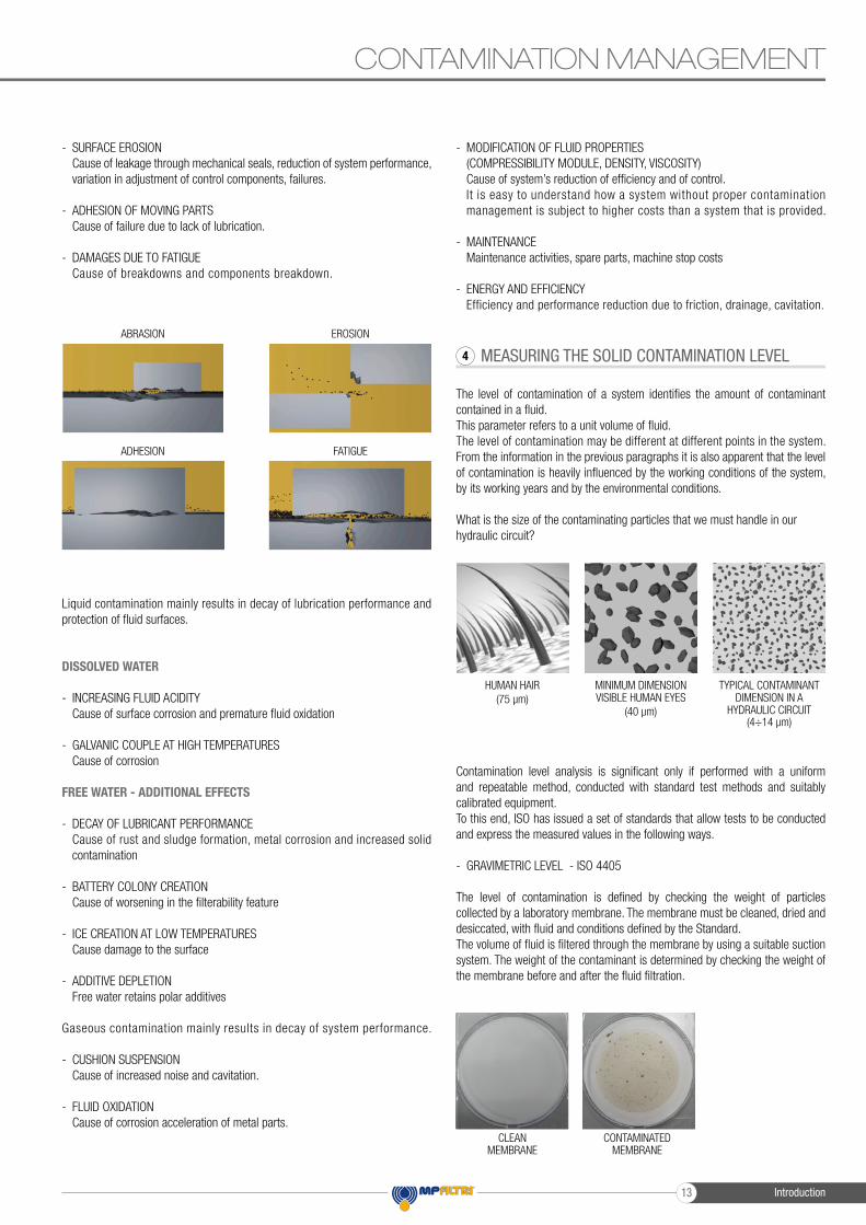
- ABRASION OF SURFACES Cause of leakage through mechanical seals, reduction of system performance, failures.
EFFECTS OF CONTAMINATION ON HYDRAULIC 3
CONTAMINATION IN PRESENCE OF LARGE TOLERANCES
CONTAMINATION IN PRESENCE OF NARROW TOLERANCES
FLUID CONTAMINATION2
HYDRAULIC FLUIDS1
Introduction 12
CONTAMINATION MANAGEMENT
- SURFACE EROSION Cause of leakage through mechanical seals, reduction of system performance, variation in adjustment of control components, failures.
- ADHESION OF MOVING PARTS Cause of failure due to lack of lubrication.
- DAMAGES DUE TO FATIGUE Cause of breakdowns and components breakdown.
Liquid contamination mainly results in decay of lubrication performance and protection of fl uid surfaces.
DISSOLVED WATER
- INCREASING FLUID ACIDITY Cause of surface corrosion and premature fl uid oxidation
- GALVANIC COUPLE AT HIGH TEMPERATURES Cause of corrosion
FREE WATER - ADDITIONAL EFFECTS
- DECAY OF LUBRICANT PERFORMANCE Cause of rust and sludge formation, metal corrosion and increased solid contamination
- BATTERY COLONY CREATION Cause of worsening in the fi lterability feature
- ICE CREATION AT LOW TEMPERATURES Cause damage to the surface
- ADDITIVE DEPLETION Free water retains polar additives
Gaseous contamination mainly results in decay of system performance.
- CUSHION SUSPENSION Cause of increased noise and cavitation.
- FLUID OXIDATION Cause of corrosion acceleration of metal parts.
- MODIFICATION OF FLUID PROPERTIES (COMPRESSIBILITY MODULE, DENSITY, VISCOSITY) Cause of system’s reduction of effi ciency and of control. It is easy to understand how a system without proper contamination management is subject to higher costs than a system that is provided.
- MAINTENANCE Maintenance activities, spare parts, machine stop costs
- ENERGY AND EFFICIENCY Efficiency and performance reduction due to friction, drainage, cavitation.
MEASURING THE SOLID CONTAMINATION LEVEL
The level of contamination of a system identifi es the amount of contaminant contained in a fl uid.This parameter refers to a unit volume of fl uid.The level of contamination may be different at different points in the system.From the information in the previous paragraphs it is also apparent that the level of contamination is heavily infl uenced by the working conditions of the system, by its working years and by the environmental conditions.
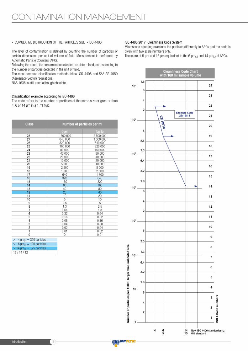
What is the size of the contaminating particles that we must handle in our hydraulic circuit?
Contamination level analysis is signifi cant only if performed with a uniform and repeatable method, conducted with standard test methods and suitably calibrated equipment.To this end, ISO has issued a set of standards that allow tests to be conducted and express the measured values in the following ways.
- GRAVIMETRIC LEVEL - ISO 4405
The level of contamination is defi ned by checking the weight of particles collected by a laboratory membrane. The membrane must be cleaned, dried and desiccated, with fl uid and conditions defi ned by the Standard.The volume of fl uid is fi ltered through the membrane by using a suitable suction system. The weight of the contaminant is determined by checking the weight of the membrane before and after the fl uid fi ltration.
ABRASION
ADHESION
EROSION
FATIGUE
MEASURING THE SOLID CONTAMINATION LEVEL4
HUMAN HAIR(75 µm)
MINIMUM DIMENSION VISIBLE HUMAN EYES
(40 µm)
TYPICAL CONTAMINANT DIMENSION IN A
HYDRAULIC CIRCUIT(4÷14 µm)
CLEAN MEMBRANE
CONTAMINATED MEMBRANE
Introduction13
CONTAMINATION MANAGEMENT
- CUMULATIVE DISTRIBUTION OF THE PARTICLES SIZE - ISO 4406
The level of contamination is defined by counting the number of particles of certain dimensions per unit of volume of fluid. Measurement is performed by Automatic Particle Counters (APC).Following the count, the contamination classes are determined, corresponding to the number of particles detected in the unit of fluid.The most common classification methods follow ISO 4406 and SAE AS 4059 (Aerospace Sector) regulations.NAS 1638 is still used although obsolete.
Classification example according to ISO 4406The code refers to the number of particles of the same size or greater than 4, 6 or 14 μm in a 1 ml fluid.
ISO 4406:2017 Cleanliness Code SystemMicroscope counting examines the particles differently to APCs and the code is given with two scale numbers only.These are at 5 µm and 15 µm equivalent to the 6 µm(c) and 14 µm(c) of APCs.
Num
ber
of p
arti
cles
per
100
ml l
arge
r th
an in
dica
ted
size
Cleanliness Code Chart with 100 ml sample volume
24
23
22
21
20
19
18
17
16
15
14
13
12
11
10
9
8
7
6
5
4
3
2
1
1.6
8
8
8
4
4
4
4 65
1415
New ISO 4406 standard µm(c) Old standard
ISO
4 C
ode
num
bers
2
2
2
1
10
102
103
104
105
106
107
5
5
6.4
6.4
2.5
2.5
3.2
3.2
1.3
1.3
1.6
1.6
Example Code22/19/1422/19/14
> 4 µm(c) = 350 particles> 6 µm(c) = 100 particles> 14 µm(c) = 25 particles16 / 14 / 12
1 300 000640 000320 000160 00080 00040 00020 00010 0005 0002 5001 300640320160804020105
2.51.30.640.320.160.080.040.020.01
0
2 500 0001 300 000640 000320 000160 00080 00040 00020 00010 0005 0002 5001 300640320160804020105
2.51.30.640.320.160.080.040.020.01
282726252423222120191817161514131211109876543210
Class Number of particles per ml
Over Up to
Introduction 14

- CUMULATIVE DISTRIBUTION OF THE PARTICLES SIZE - SAE AS 4059-1 and SAE AS 4059-2
Classification example according to SAE AS 4059-1 and SAE AS 4059-2The code, prepared for the aerospace industry, is based on the size, quantity, and particle spacing in a 100 ml fluid sample. The contamination classes are defined by numeric codes, the size of the contaminant is identified by letters (A-F).
It can be made a differential measurement (Table 1) or a cumulative measurement (Table 2)
- CLASSES OF CONTAMINATION ACCORDING TO NAS 1638 (January 1964)
The NAS system was originally developed in 1964 to define contamination classes for the contamination contained within aircraft components. The application of this standard was extended to industrial hydraulic systems simply because nothing else existed at the time.The coding system defines the maximum numbers permitted of 100ml volume at various size intervals (differential counts) rather than using cumulative counts as in ISO 4406:1999. Although there is no guidance given in the standard on how to quote the levels, most industrial users quote a single code which is thehighest recorded in all sizes and this convention is used on MP Filtri APC’s.
The contamination classes are defined by a number (from 00 to 12) which indicates the maximum number of particles per 100 ml, counted on a differential basis, in a given size bracket.
- CUMULATIVE DISTRIBUTION OF THE PARTICLES SIZE - ISO 4407
The level of contamination is defined by counting the number of particles collected by a laboratory membrane per unit of fluid volume. The measurement is done by a microscope.The membrane must be cleaned, dried and desiccated, with fluid and conditions defined by the Standard. The fluid volume is filtered through the membrane, using a suitable suction system.The level of contamination is identified by dividing the membrane into a predefined number of areas and by counting the contaminant particles using a suitable laboratory microscope.
CONTAMINATION MANAGEMENT
195390780
1 5603 1206 250
12 50025 00050 000
100 000200 000400 000800 000
1 600 0003 200 000
76152304609
1 2172 4324 8649 731
19 46238 92477 849
155 698311 396622 792
1 245 584
142754
109217432864
1 7313 4626 924
13 84927 69855 396
110 792221 584
35
10203976
152306612
1 2242 4494 8989 796
19 59239 184
11247
132653
106212424848
1 6963 3926 784
00011248
163264
128256512
1 024
000000123456789101112
Class Dimension of contaminant
>4 µm(c)A
>6 µm(c)B
>14 µm(c)C
>21 µm(c)D
>38 µm(c)E
>70 µm(c)F
Table 2 - Class for cumulative measurement
125250500
1 0002 0004 0008 000
16 00032 00064 000
128 000256 000512 000
1 024 000
224489
178356712
1 4252 8505 700
11 40022 80045 60091 200
182 400
48
163263
126253506
1 0122 0254 0508 100
16 20032 400
1236
11224590
180360720
1 4402 8805 760
0011248
163264
128256512
1 024
000123456789101112
Class Dimension of contaminant
6÷14 µm(c) 14÷21 µm(c) 21÷38 µm(c) 38÷70 µm(c) >70 µm(c)
Table 1 - Class for differential measurement
6÷14 µm(c) = 15 000 particles14÷21 µm(c) = 2 200 particles21÷38 µm(c) = 200 particles38÷70 µm(c) = 35 particles> 70 µm(c) = 3 particlesClass 6
> 4 µm(c) = 45 000 particles> 6 µm(c) = 15 000 particles> 14 µm(c) = 1 500 particles> 21 µm(c) = 250 particles> 38 µm(c) = 15 particles> 70 µm(c) = 3 particleClass from 2F to 4E
Size Range Classes (in microns)
Maximum Contamination Limits per 100 ml
000123456789
101112
125250500
1 0002 0004 0008 000
16 00032 00064 000
128 000256 000512 000
1 024 000
224489
178356712
1 4252 8505 700
11 40022 80045 60091 200
182 400
48
163263
126253506
1 0122 0254 0508 100
16 20032 400
1236
11224590
180360720
1 4402 8805 760
0011248
163264
128256512
1 024
5÷15 15÷25 25÷50 50÷100 >100Class
5÷15 µm(c) = 42 000 particles15÷25 µm(c) = 2 200 particles25÷50 µm(c) = 150 particles50÷100 µm(c) = 18 particles> 100 µm(c) = 3 particlesClass NAS 8
MICROSCOPE CONTROL AND MEASUREMENT
COMPARISON PHOTOGRAPH’S
ISO 4406:1999SAE AS4059E Table 1NAS 1638SAE AS4059E Table 2
Class 16/14/11Class 5Class 5Class 6A/5B/5C
Class 22/20/17Class 11Class 11Class 12A/11B/11C
1 graduation = 10µm
Introduction15

- CLEANLINESS CODE COMPARISON
Although ISO 4406:2017 standard is being used extensively within the hydraulics industry other standards are occasionally required and a comparison may be requested. The table below gives a very general comparison but often no direct comparison is possible due to the different classes and sizes involved.
FILTRATION TECHNOLOGIES
Various mechanisms such as mechanical stoppage, magnetism, gravimetric deposit , or centr i fugal separat ion can be used to reduce the level of contamination.The mechanical stoppage method is most effective and can take place in two ways:
- SURFACE FILTRATION It is by direct interception. The fi lter prevents particles larger than the pores from continuing in the plant / system. Surface f i l ters are generally manufactured with metal canvases or meshes.
- DEPTH FILTERING Filters are constructed by fiber interlacing. Such wraps form pathways of different shapes and sizes in which the particles remain trapped when they fi nd smaller apertures than their diameter. Depth fi lters are generally produced with papers impregnated with phenolic resins, metal fi bers or inorganic fi bers. In inorganic fi ber fi ltration, commonly called microfi bre, the fi ltering layers are often overlapped in order to increase the abil i ty to retain the contaminant.
The fi ltration effi ciency of metallic mesh fi ltrations is defi ned as the maximum particle size that can pass through the meshes of the fi ltering grid.The effi ciency of microfi bre and paper fi ltration (ßx(c)) is defi ned through a lab test called Multipass Test. The effi ciency value (ßx(c)) is defi ned as the ratio between the number of particles of certain dimensions detected upstream and downstream of the fi lter.
Test conditions, such as type of fl uid to be used (MIL-H-5606), type of contaminant to be used (ISO MTD), fl uid viscosity, test temperature, are determined by ISO 16889.In addition to the fi ltration effi ciency value during the Multipass test, other important features, such as fi ltration stability (ß stability) and dirt holding capacity (DHC), are also tested.Poor fi ltration stability is the cause of the fi ltering quality worsening as the fi lter life rises. Low dirt holding capacity causes a reduction in the life of the fi lter.
FILTRATION TECHNOLOGIES5
WIRE MESH FILTRATION PAPER FILTRATION MICROFIBER FILTRATION
MICROFIBER FILTRATION
External protective wire mesh
Pre-fi ltration layerFiltration layerInner support layerInner protective wire mesh
Support pipe
5 µm(c)7 µm(c)
10 µm(c)16 µm(c)21 µm(c)
3 µm6 µm
10 µm18 µm25 µm
Filtration ISO Standard Comparisonßx(c) > 1000
ISO 16889ßx > 200 ISO 4572
MP Filtri Filter media code
A03A06A10A16A25
Upstream particles number > X µm(c)= ßx(c)
Downstream particles number > X µm(c)
2
50%
10
90%
75
98.7%
100
99%
200
99.5%
1000
99.9%
Value (ßx(c))
Effi ciency
CONTAMINATION MANAGEMENT
23 / 21 / 18
22 / 20 / 17
21 / 19 / 16
20 / 18 / 15
19 / 17 / 14
18 / 16 / 13
17 / 15 / 12
16 / 14 / 11
15 / 13 / 10
14 / 12 / 09
13A / 12B / 12C
12A / 11B / 11C
11A / 10B / 10C
10A / 9B / 9B
9A / 8B / 8C
8A / 7B / 7C
7A / 6B / 6C
6A / 5B / 5C
5A / 4B / 4C
4A / 3B / 3C
12
11
10
9
8
7
6
5
4
3
12
11
10
9
8
7
6
5
4
3
ISO 4406:2017 SAE AS4059Table 2
SAE AS4059Table 1
NAS 1638
> 4 µm(c)6 µm(c)
14 µm(c)
> 4 µm(c)6 µm(c)
14 µm(c)
4-6 6-14
14-21 21-38 38-70 >70
5-1515-2525-50
50-100>100
Introduction 16

RECOMMENDED CONTAMINATION CLASSES
Any are the nature and the properties of fl uids, they are inevitably subject to contamination. The level of contamination can be managed by using special components called fi lters.Hydraulic components builders, knowing the problem of contamination, recommend the fi ltration level appropriate to the use of their products.
Example of recommended contamination levels for pressures below 140 bar.
The common classifi cation of fi lters is determined by their position in the plant.
TYPES OF FILTERS
Suction fi ltersThey are positioned before the pump and are responsible for protecting the pump from dirty contaminants. It also provides additional fl ow guidance to the pump suction line.Being subject to negligible working pressures are manufactured with simple and lightweight construction.They are mainly produced with gross grade surface fi ltrations, mainly 60 ÷ 125 μm.They can be equipped with a magnetic column for retaining ferrous particles.They are generally placed under the fl uid head to take advantage of the piezometric thrust of the fl uid and reduce the risk of cavitation.
There are two types of suction fi lters:- IMMERSION FILTERS Simple fi lter element screwed on the suction pipe
- FILTERS WITH CONTAINER Container fi lters that are more bulky, but provide easier maintenance of the tank
Delivery (or Pressure) fi ltersThey are positioned between the pump and most sensitive regulating and controlling components, such as servo valves or proportional valves, and are designed to ensure the class of contamination required by the components used in the circuit.
Being subjected to high working pressures are manufactured with more robust and articulated construction. In particular situations of corrosive environments or aggressive fl uids can be made of stainless steel.They are mainly produced with fi ltering depths of 3 ÷ 25 μm.They can be manufactured with in-line connections, with plate or fl ange connections or directly integrated into the circuit control blocks / manifolds.They can also be manufactured in duplex confi guration to allow the contaminated section to be maintained even when the plant / system is in operation without interruption of the working cycle.
Return fi ltersThey are positioned on the return line to the tank and perform the task of fi ltering the fl uid from particles entering the system from the outside or generated by the wear of the components.They are generally fi xed to the reservoir (for this reason also called top tank mounted), positioned semi-immersed or completely immersed.The positioning of the return fi lters must guarantee in all operating conditions that the fl uid drainage takes place in immersed condition; this is to avoid creating foams in the tank that can cause malfunctions or cavitation in the pumps.For the sizing of the return fi lters, account must be taken of the presence of accumulators or cylinders that can make the return fl ow considerably greater than the pump suction fl ow rate.Being subject to contained working pressures are manufactured with simple and lightweight construction.Normally it is possible to extract the fi lter element without disconnecting the fi lter from the rest of the system.
Combined fi ltersThey are designed to be applied to systems with two or more circuits. They are commonly used in hydrostatic transmission machines where they have a dual fi ltration function of the return line and suction line of the hydrostatic transmission pump.The fi lter is equipped with a valve that keeps the 0.5 bar pressure inside the fi lter. A portion of the fl uid that returns to the tank is fi ltered by the return fi lter element, generally produced with absolute fi ltration, and returns to the transmis-sion booster pump.Only excess fl uid returns to the tank through the valve.The internal pressure of the fi lter and the absolute fi ltration help to avoid the cavitation phenomenon inside the pump.
Off-line fi ltersThey are generally used in very large systems / plants, placed in a closed circuit independent from the main circuit. They remain in operation regardless of the operation of the main circuit and are crossed by a constant fl ow rate.They can also be manufactured in duplex confi guration to allow the contaminated section to be maintained even when the unit is in operation without interruption of the work cycle.
Venting fi ltersDuring the operation of the plants, the fl uid level present in the reservoir changes continuously. The result of this continuous fl uctuation is an exchange of air with the outside environment. The venting fi lter function, positioned on the tank, is to fi lter the air that enters the tank to compensate for fl uid level variations.
RECOMMENDED CONTAMINATION CLASSES6
TYPES OF FILTERS7
CONTAMINATION MANAGEMENT
Piston pumps with fi xed fl ow ratePiston pumps with variable fl ow rateVane pumps with fi xed fl ow rateVane pumps with variable fl owEnginesHydraulic cylindersActuatorsTest benchesCheck valveDirectional valvesFlow regulating valvesProportional valvesServo-valvesFlat bearingsBall bearingsISO 4406 CODERecommended fi ltration ßx(c)≥1.000
•
•
•
•
••
••
•
•
•
•
•••
20/18/15ß20(c)
>1000
17/15/12ß7(c)
>1000
19/17/14ß15(c)
>1000
16/14/11ß7(c)
>1000
18/16/13ß10(c)
>1000
15/13/10ß5(c)
>1000
Introduction17

FILTER SIZING PARAMETERS
The choice of the fi lter system for an hydraulic system is infl uenced by several factors.It is necessary to consider the characteristics of the various components present in the plant and their sensitivity to contamination.
It is also necessary to consider all the tasks that the fi lter will have to do within the plant:- FLUID PROTECTION FROM CONTAMINATION- PROTECTION OF OLEODYNAMIC COMPONENTS SENSITIVE TO CONTAMINATION- PROTECTION OF OLEODYNAMIC PLANTS FROM ENVIRONMENTAL WASTE- PROTECTION OF OLEODYNAMIC PLANTS FROM CONTAMINATION CAUSED BY COMPONENTS’ FAILURES
The advantages of proper positioning and sizing of the fi lters are- MORE RELIABILITY OF THE SYSTEM- LONGER LIFE OF THE FLUID COMPONENTS- REDUCTION OF STOP TIME- REDUCTION OF FAILURE CASUALITIES
Each hydraulic fi lter is described by general features that identify the possibility of use in different applications.
• MAXIMUM WORKING PRESSURE (Pmax) The maximum working pressure of the filter must be greater than or equal to the pressure of the circuit section in which it will be installed.
• PRESSURE DROP (∆P) The pressure drop depends on a number of factors, such as the working circuit temperature, the fl uid viscosity, the fi lter element cleaning condition.
• WORKING TEMPERATURE (T) The working temperature deeply affect the choice of materials. Excessively high or low temperatures may adversely affect the strength of the materials or the characteristics of the seals.
• FILTRATION EFFICIENCY (%) / FILTRATION RATIO (ßx(c)) Filtration efficiency is the most important parameter to consider when selecting a fi lter. When choosing the filtration performances, the needs of the most sensitive components in the system must be considered.
• FLUID TYPE The type of fl uid infl uences the choice of fi lters in terms of compatibility and viscosity. It is always mandatory to check the fi lterability.
• PLACEMENT IN THE PLANT The position of the filter in the system conditions the efficiency of all filter performances.
APPLICABLE STANDARDS FOR FILTER DEVELOPMENT
In order to obtain unique criteria for development and verification of the fi lters performance, specifi c regulations for the fi lters and fi lter elements testing have been issued by ISO. These norms describe the target, the methodology, the conditions and the presentation methods for the test results.
ISO 2941Hydraulic fl uid power -- Filter elements -- Verifi cation of collapse/burst pressure ratingThis Standard describes the method for testing the collapse / burst resistance of the fi lter elements.The test is performed by crossing the contaminated fl uid fi lter element at a predefi ned fl ow rate. The progressive clogging of the fi lter element, determined by contamination, causes an increase in differential pressure.
ISO 2942Hydraulic fl uid power -- Filter elements -- Verifi cation of fabrication integrity and determination of the fi rst bubble pointThis Standard describes the method to verify the integrity of the assembled fi lter elements.It can be used to verify the quality of the production process or the quality of the materials by verifying the pressure value of the fi rst bubble point.
ISO 2943Hydraulic fl uid power -- Filter elements -- Verifi cation of material compatibility with fl uidsThis Standard describes the method to verify the compatibility of materials with certain hydraulic fl uids.The test is carried out by keeping the element (the material sample) immersed in the fl uid under high or low temperature conditions for a given period of time and verifying the retention of the characteristics.
ISO 3723Hydraulic fl uid power -- Filter elements -- Method for end load testThis Standard describes the method for verifying the axial load resistance of the fi lter elements.After performing the procedure described in ISO 2943, the designed axial load is applied to the fi lter element. To verify the test results, then the test described in ISO 2941 is performed.
ISO 3968Hydraulic fl uid power -- Filters -- Evaluation of differential pressure versus fl ow characteristicsThis Standard describes the method for checking the pressure drop across the fi lter.The test is carried out by crossing the fi lter from a given fl uid and by detecting upstream and downstream pressures.Some of the parameters defi ned by the Standard are the fl uid, the test temperature, the size of the tubes, the position of the pressure detection points.
ISO 16889Hydraulic fl uid power -- Filters -- Multi-pass method for evaluating fi ltrationperformance of a fi lter elementThis Standard describes the method to check the fi ltration characteristics of the fi lter elements.The test is performed by constant introduction of contaminant (ISO MTD).The characteristics observed during the test are the fi ltration effi ciency and the dirty holding capacity related to the differential pressure.
FILTER SIZING PARAMETERS8 APPLICABLE STANDARDS FOR FILTER DEVELOPMENT9
CONTAMINATION MANAGEMENT
Introduction 18

ISO 23181Hydraulic fl uid power -- Filter elements -- Determination of resistance to fl ow fatigue using high viscosity fl uidThis Standard describes the method for testing the fatigue resistance of the fi lter elements.The test is carried out by subjecting the fi lter to continuous fl ow variations, thus differential pressure, using a high viscosity fl uid.
ISO 11170Hydraulic fl uid power -- Sequence of tests for verifying performance characteristics of fi lter elementsThe Standard describes the method for testing the performance of fi lter elements. The protocol described by the regulations provides the sequence of all the tests described above in order to verify all the working characteristics (mechanical, hydraulic and fi ltration).
ISO 10771-1Hydraulic fl uid power -- Fatigue pressure testing of metal pressure-containing envelopes -- Test methodThis Standard describes the method to check the resistance of the hydraulic components with pulsing pressure.It can be applied to all metal components (excluding tubes) subject to cyclic pressure used in the hydraulic fi eld.
WATER IN HYDRAULIC AND LUBRICATING FLUIDS
Water Content
In mineral oils and non aqueous resistant fl uids water is undesirable. Mineral oil usually has a water content of 50-300 ppm (@40°C) which it can support without adverse consequences.Once the water content exceeds about 300ppm the oil starts to appear hazy. Above this level there is a danger of free water accumulating in the system in areas of low fl ow. This can lead to corrosion and accelerated wear.Similarly, fire resistant fluids have a natural water which may be different to mineral oil.
Saturation Levels
Since the effects of free (also emulsifi ed) water is more harmful than those of dissolved water, water levels should remain well below the saturation point.
However, even water in solution can cause damage and therefore every reasonable effort should be made to keep saturation levels as low as possible.There is no such thing as too little water. As a guideline, we recommend maintaining saturation levels below 50% in all equipment.
TYPICAL WATER SATURATION LEVEL FOR NEW OILSExamples:Hydraulic oil @ 30°C = 200ppm = 100% saturationHydraulic oil @ 65°C = 500ppm = 100% saturation
10
CONTAMINATION MANAGEMENT
Saturation point
Emulsified
Dis
solv
ed w
ater
Free
wat
er
- 0%
- 25%
- 50%
- 75%
- 100%
Part
s pe
r m
illio
n
Temperature °C
20
200
400
600
030 40 50 60 70
Hydraulic oilGear oilTurbine oil
Introduction19
Water absorber
Water is present everywhere, during storage, handling and servicing.
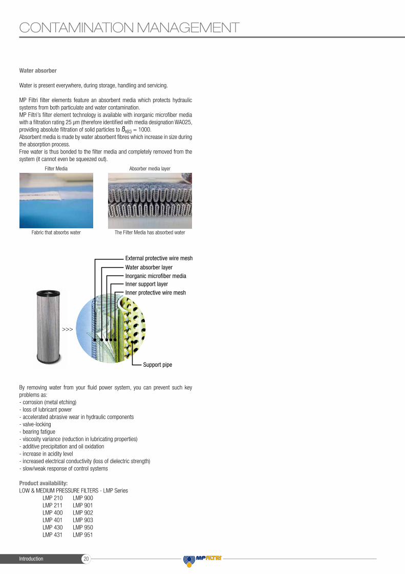
MP Filtri filter elements feature an absorbent media which protects hydraulic systems from both particulate and water contamination.MP Filtri’s filter element technology is available with inorganic microfiber media with a filtration rating 25 μm (therefore identified with media designation WA025, providing absolute filtration of solid particles to ßx(c) = 1000.Absorbent media is made by water absorbent fibres which increase in size during the absorption process.Free water is thus bonded to the filter media and completely removed from the system (it cannot even be squeezed out).
By removing water from your fluid power system, you can prevent such key problems as:- corrosion (metal etching)- loss of lubricant power- accelerated abrasive wear in hydraulic components- valve-locking- bearing fatigue- viscosity variance (reduction in lubricating properties)- additive precipitation and oil oxidation- increase in acidity level- increased electrical conductivity (loss of dielectric strength)- slow/weak response of control systems
Product availability:LOW & MEDIUM PRESSURE FILTERS - LMP Series LMP 210 LMP 900 LMP 211 LMP 901 LMP 400 LMP 902 LMP 401 LMP 903 LMP 430 LMP 950 LMP 431 LMP 951
CONTAMINATION MANAGEMENT
Filter Media Absorber media layer
Fabric that absorbs water The Filter Media has absorbed water
>>>
External protective wire mesh
Water absorber layerInorganic microfiber mediaInner support layerInner protective wire mesh
Support pipe
Introduction 20

CONTAMINATION MANAGEMENT
Introduction21

FILTER SIZING
CALCULATION
CORRECTIVE FACTOR
23
24
Page
INDEX
Introduction
Introduction 22
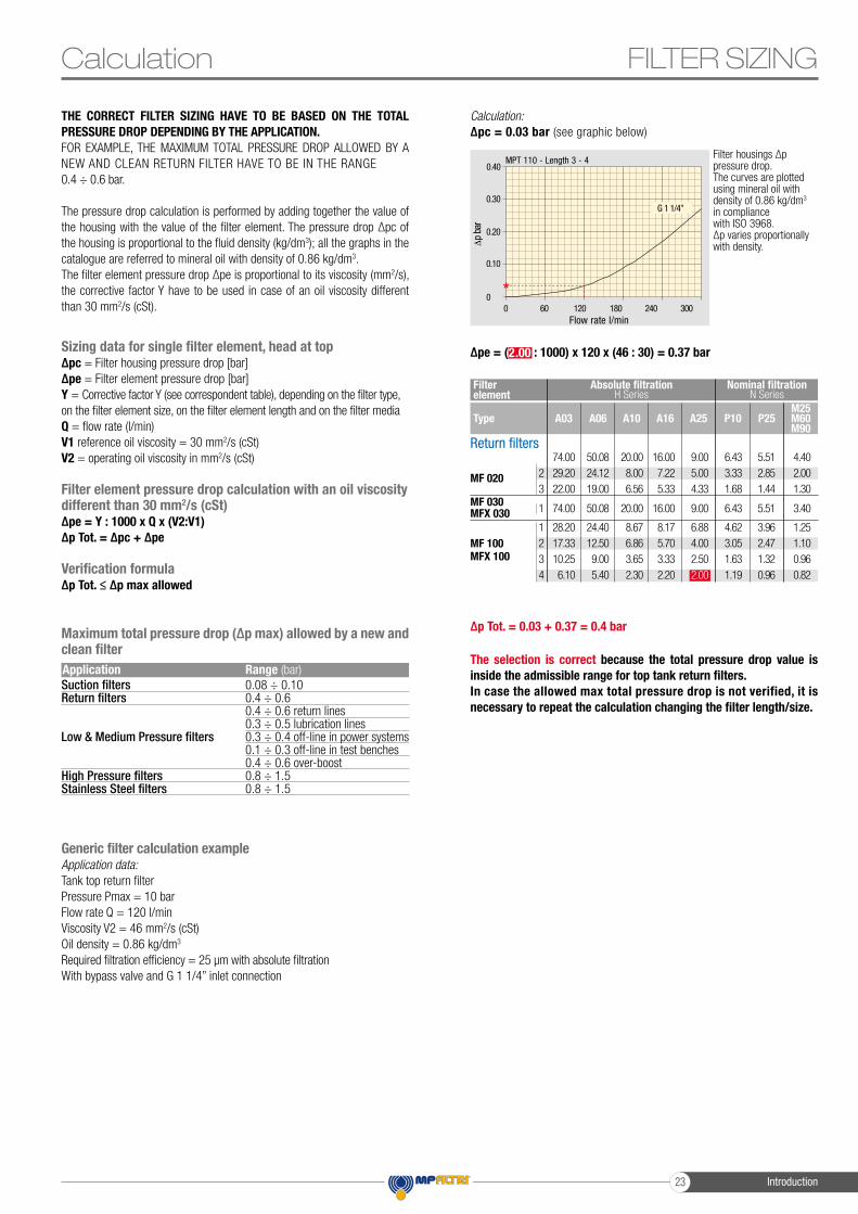
∆p Tot. = 0.03 + 0.37 = 0.4 bar
The selection is correct because the total pressure drop value is inside the admissible range for top tank return filters.In case the allowed max total pressure drop is not verified, it is necessary to repeat the calculation changing the filter length/size.
THE CORRECT FILTER SIZING HAVE TO BE BASED ON THE TOTAL PRESSURE DROP DEPENDING BY THE APPLICATION. FOR EXAMPLE, THE MAXIMUM TOTAL PRESSURE DROP ALLOWED BY A NEW AND CLEAN RETURN FILTER HAVE TO BE IN THE RANGE 0.4 ÷ 0.6 bar.
The pressure drop calculation is performed by adding together the value of the housing with the value of the filter element. The pressure drop ∆pc of the housing is proportional to the fluid density (kg/dm3); all the graphs in the catalogue are referred to mineral oil with density of 0.86 kg/dm3.The filter element pressure drop ∆pe is proportional to its viscosity (mm2/s), the corrective factor Y have to be used in case of an oil viscosity different than 30 mm2/s (cSt).
Generic filter calculation exampleApplication data:Tank top return filterPressure Pmax = 10 barFlow rate Q = 120 l/minViscosity V2 = 46 mm2/s (cSt)Oil density = 0.86 kg/dm3
Required filtration efficiency = 25 μm with absolute filtrationWith bypass valve and G 1 1/4” inlet connection
Calculation:∆pc = 0.03 bar (see graphic below)
*
0.40
0.30
0.20
0.10
0
MPT 110 - Length 3 - 4
Δp
bar
0 60 120 180 240 300Flow rate l/min
G 1 1/4”
Filter housings ∆p pressure drop.The curves are plotted using mineral oil with density of 0.86 kg/dm3 in compliance with ISO 3968. ∆p varies proportionally with density.
Maximum total pressure drop (∆p max) allowed by a new and clean filter
Filter element
Absolute filtration Nominal filtration
Type A03 A16A06 A25A10 P10 P25M25M60M90
H Series N Series
123
MF 020
74.0029.2022.00
50.0824.1219.00
20.008.006.56
16.007.225.33
6.433.331.68
5.512.851.44
4.402.001.30
9.005.004.33
1MF 030MFX 030 74.00 50.08 20.00 16.00 6.43 5.51 3.409.00
1234
MF 100MFX 100
28.2017.3310.256.10
24.4012.509.005.40
8.676.863.652.30
8.175.703.332.20
4.623.051.631.19
3.962.471.320.96
1.251.100.960.82
6.884.002.502.00
Return filters
Suction filtersReturn filters
Low & Medium Pressure filters
High Pressure filtersStainless Steel filters
0.08 ÷ 0.100.4 ÷ 0.60.4 ÷ 0.6 return lines0.3 ÷ 0.5 lubrication lines0.3 ÷ 0.4 off-line in power systems0.1 ÷ 0.3 off-line in test benches0.4 ÷ 0.6 over-boost0.8 ÷ 1.50.8 ÷ 1.5
Application Range (bar)
∆pe = (2.00 : 1000) x 120 x (46 : 30) = 0.37 barSizing data for single filter element, head at top∆pc = Filter housing pressure drop [bar]∆pe = Filter element pressure drop [bar]Y = Corrective factor Y (see correspondent table), depending on the filter type, on the filter element size, on the filter element length and on the filter mediaQ = flow rate (l/min)V1 reference oil viscosity = 30 mm2/s (cSt)V2 = operating oil viscosity in mm2/s (cSt)
Filter element pressure drop calculation with an oil viscosity different than 30 mm2/s (cSt)∆pe = Y : 1000 x Q x (V2:V1)∆p Tot. = ∆pc + ∆pe
Verification formula∆p Tot. ≤ ∆p max allowed
FILTER SIZINGCalculation
Introduction23

Type A03 A16A06 A25A10 P10 P25M25M60M90
1234
CU 110
16.2512.628.575.76
15.1610.44
7.954.05
8.756.115.072.80
8.146.024.072.36
5.874.162.401.14
2.861.601.240.91
2.651.491.150.85
0.140.120.110.05
FILTER SIZING Corrective factorCorrective factor Y to be used for the filter element pressure drop calculation. The values depend to the filter size and length and to the filter media.Reference oil viscosity 30 mm2/s
Filter element
Absolute filtration Nominal filtration
Type A03 A16A06 A25A10 P10 P25M25M60M90
M25
H Series N Series
123
MF 02074.0029.2022.00
50.0824.1219.00
20.008.006.56
16.007.225.33
9.005.004.33
6.433.331.68
5.512.851.44
4.402.001.30
123
MF 400MFX 400
3.202.001.90
2.751.871.60
1.390.880.63
1.330.850.51
1.060.550.49
0.960.490.39
0.870.450.35
0.220.130.11
1234
MR 250
5.354.002.601.84
4.853.282.201.56
2.321.441.080.68
1.921.101.000.56
1.501.070.860.44
1.380.960.770.37
1.200.830.640.23
0.150.130.120.11
1234
MR 850
0.600.370.270.23
0.430.260.180.16
0.340.230.170.13
0.250.210.170.12
0.130.110.050.04
0.120.080.040.03
0.090.070.040.03
0.030.030.020.02
12345
MR 100
19.0011.707.805.504.20
17.0010.806.874.973.84
6.904.403.702.602.36
6.304.303.102.402.15
4.603.002.702.181.90
2.942.942.141.721.60
2.522.521.841.471.37
1.601.371.341.341.34
12345
MR 630
3.102.061.481.300.74
2.481.921.301.200.65
1.320.820.600.480.30
1.140.760.560.400.28
0.920.380.260.250.13
0.830.330.220.210.10
0.730.270.170.160.08
0.090.080.080.080.04
12
MF 180MFX 180
3.671.69
3.051.37
1.640.68
1.560.54
1.240.51
1.180.43
1.060.39
0.260.12
1MF 030MFX 030 74.00 50.08 20.00 16.00 9.00 6.43 5.51 3.40
2MF 190MFX 190 1.69 1.37 0.60 0.49 0.44 0.35 0.31 0.11
2MLX 250 3.00 3.04 1.46 1.25 1.17 - - 0.20
M25
2MLX 660 1.29 1.26 0.52 0.44 0.38 - - 0.10
1MF 750MFX 750 1.08 0.84 0.49 0.36 0.26 0.21 0.19 0.06
CU 025
CU 040
CU 100
CU 250
CU 630
78.00
25.88
15.20
3.25
1.96
1.06
48.00
20.88
14.53
2.55
1.68
0.84
28.00
10.44
5.14
1.55
0.85
0.42
24.00
10.00
4.95
1.35
0.72
0.33
9.33
3.78
2.00
0.71
0.42
0.17
9.33
3.78
2.00
0.71
0.42
0.17
8.51
3.30
0.17
0.59
0.36
0.13
1.25
1.25
1.10
0.25
0.09
0.04CU 850
1234
MF 100MFX 100
28.2017.3310.256.10
24.4012.509.005.40
8.676.863.652.30
8.175.703.332.20
4.623.051.631.19
3.962.471.320.96
1.251.100.960.82
6.884.002.502.00
Return filters
Low & Medium pressure filters
123
CU 2105.303.442.40
4.802.951.70
2.001.240.94
1.661.090.84
1.320.700.54
0.560.420.33
0.430.350.23
0.120.090.05
016025040
DN7.955.003.13
7.204.532.66
3.001.891.12
2.491.570.98
1.981.250.63
0.840.530.38
0.650.410.32
0.180.110.08
1234
CU 110
16.2512.628.575.76
15.1610.44
7.954.05
8.756.115.072.80
8.146.024.072.36
5.874.152.401.14
2.861.601.240.91
2.651.491.150.85
0.140.120.110.05
CU 400
23456
3.132.151.601.000.82
2.551.701.280.830.58
1.460.940.710.470.30
1.220.780.610.340.27
0.780.500.400.200.17
0.750.400.340.240.22
0.640.340.270.190.18
0.190.100.080.060.05
Filter element
Absolute filtration Nominal filtration
Type A03 A16A06 A25A10 P10 P25 M25
N-W Series N Series
CU 95023
1.030.44
0.800.40
0.590.27
0.400.18
0.260.15
--
--
0.050.02
1CU 900 0.86 0.63 0.32 0.30 0.21 - - 0.05
MR 630 7 0.88 0.78 0.36 0.34 0.120.16 0.96 0.47
Return / Suction filters
123
RSX 1652.061.240.94
1.751.050.86
1.460.960.61
12RSX 116
Filter element
Filter element
Type
Absolute filtration
Absolute filtration
A16 A25A10
5.122.22
4.331.87
3.851.22
N Series
Introduction 24

123
HF 3203.652.031.84
2.951.731.42
2.801.611.32
1.801.351.22
0.900.850.80
0.380.360.35
Type A03 A16A06 A25A10
FILTER SIZING
Stainless steel high pressure filtersFilter element
Filter element
Absolute filtration
Absolute filtration
Type A03 A16A06 A25A10
N Series
H - U Series
1234
HP 011
128.3637.0520.7216.17
152.3659.1333.0822.67
184.3274.0841.4828.37
250.07165.56
92.6858.52
332.71220.28123.24
77.76
1234
HP 011
163.7847.2621.8118.40
194.4475.4534.8229.37
235.1794.5343.6336.79
319.74211.25
97.5082.25
424.58281.06130.14109.39
12345
HP 050
7.294.903.633.082.25
12.39.097.185.753.10
13.1611.70
8.906.103.60
30.3021.2616.2510.75
6.56
31.7524.2517.3712.12
7.00
12345
HP 050
14.715.884.363.692.50
20.5010.90
8.616.904.80
21.5014.0410.68
7.326.40
34.2525.9519.5012.90
9.34
47.3329.1020.8514.55
9.86
234
HP 03914.67
8.005.58
20.5713.38
8.80
25.7718.0012.46
53.2032.2823.27
70.6636.5726.57
234
HP 03917.2011.20
6.70
24.0018.80
9.30
28.0021.8817.22
57.0036.3328.22
73.0040.9031.50
123
HP 1354.782.222.14
8.666.383.16
9.716.603.38
18.8010.16
6.33
20.3311.14
6.48
123
HP 1355.924.443.07
12.477.604.16
13.007.864.89
25.3311.04
7.46
29.1614.28
8.96
High pressure filtersFilter element
Filter element
Type
Type
Absolute filtration
Absolute filtration
Nominal filtration
Nominal filtration
A03
A03
A16
A16
A06
A06
A25
A25
A10
A10
M25
M25
N - R Series
N Series
N Series
N Series
1234
HP 011
----
332.71220.28123.2477.76
250.07165.5692.6858.52
184.3274.0841.4828.37
152.3659.1333.0822.67
128.3637.0520.7216.17
1234
HP 320
10.884.402.752.12
9.733.832.111.77
5.021.751.050.98
3.731.480.870.78
2.540.880.770.55
1.040.710.610.47
234
HP 03970.6636.5726.57
53.2032.2823.27
25.7718.0012.46
20.5713.38
8.80
14.678.005.58
4.902.902.20
123
HP 06558.5042.6020.50
43.4625.6415.88
23.1616.22
8.18
19.6613.88
6.81
10.717.323.91
1.281.110.58
123
HP 13520.3311.146.48
18.8010.16
6.33
9.716.603.38
8.666.383.16
4.782.222.14
2.781.111.01
123
HP 15017.538.606.53
15.918.375.90
7.483.542.93
6.963.382.79
5.943.152.12
1.070.580.49
12345
HP 050
31.7524.2517.3712.127.00
30.3021.2616.2510.75
6.56
13.1611.70
8.906.103.60
12.39.097.185.753.10
7.294.903.633.082.25
1.601.401.251.070.80
12345
HP 500
4.443.372.221.811.33
3.672.771.981.331.15
2.301.781.110.930.77
2.101.681.090.860.68
1.651.240.750.680.48
0.150.100.080.050.04
Corrective factorCorrective factor Y to be used for the filter element pressure drop calculation. The values depend to the filter size and length and to the filter media.Reference oil viscosity 30 mm2/s
Suction filters
SF 250
Filter element
Type
Nominal filtration
P25P10
65 21
N Series
Introduction25

Choose fi lter type (MPF, MPT, etc.) in function of the max working pressure and the max fl ow rate
Step 3
FILTER SIZINGSelect “FILTERS”Step 1
Choose fi lter group (Return Filter, Pressure Filter, etc.)Step 2
Push “PROCEED”Step 4
Download PDF Datasheet “Report.aspx” pushing the button “Drawing”
Step 7
Insert all application data to calculate the fi lter size following the sequence: - working pressure- working fl ow rate- working pressure drop- working temperature- fl uid material and fl uid type- fi ltration media- connection type
Step 5
Push “CALCULATE” to have result; in case of any mistake, the system will advice which parameter is out of range to allow to modify/adjust the selection
Step 6
Selection Software
Introduction 26

FILTER SIZING
Introduction27
Spin-On filters are used as process and safety filters to protect individual pumps, valves or the entire hydraulic circuit from contamination as per ISO 4406.
In-line Spin-On filters can be used for the following purposes:- Suction filters- On the return circuit, for mounting on the line or on the tank cover- In-line for low and medium pressure applications
Spin-On filters are available in 4 configurations:- Single cartridge in-line- In-line with two parallel cartridges on the same axis- In-line with two parallel cartridges mounted side by side
All versions may be equipped with visual and/or electrical blockage indicators.
Spin-on filters 286

Spin-on filters
MPS
MSH
INDICATORS
289
305
311
page
Spin-on filters287

Spin-on filters 288
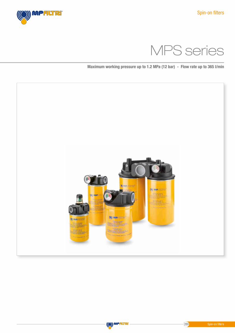
MPS seriesMaximum working pressure up to 1.2 MPa (12 bar) - Flow rate up to 365 l/min
Spin-on fi lters
Spin-on fi lters289

- Head: Aluminium- Bypass valve: Nylon - Steel- Element: Zinc-Plated Steel - Painted Steel
Filter housing materials
MPS
Spin-on fi lters
From -20 °C to +110 °CTemperature
- Return fi lter opening pressure: 175 kPa (1.75 bar) ±10%- Suction fi lter opening pressure: 30 kPa (0.3 bar) ±10%
Bypass valve
- ∆p: 5 bar- Fluid fl ow through the fi lter element from OUT to IN
∆p element type
Standard NBR - series ASeals
MPS fi lters are provided for vertical mounting
Note
GENERAL INFORMATION
Maximum working pressure up to 1.2 MPa (12 bar)Flow rate up to 365 l/min
MPS is a range of spin-on fi lters suitable to be used in suction, return and low pressure lines.They offer a good balance between performances, dimensions and prices.They are directly connected to the lines of the system through the hydraulic fi ttings.
Available features:- Female threaded connections up to 1 1/2” and fl anged connections up to 1 1/2”, for a maximum fl ow rate of 365 l/min.- Fine fi ltration rating, to get a good cleanliness level into the reservoir- Water removal elements, to remove the free water from the hydraulic fl uid- Double connection for the cans, to fit both European and American standard elements- Double cans fi tting, to increase the life time of the fi lter- Bypass valve, to relieve excessive pressure drop across the fi lter media- Visual, electrical and electronic clogging indicators for suction and return applications- Visual, electrical and electronic differential clogging indicators for low pressure applications
Common applications:- Suction lines, Return lines, Delivery lines, in economic industrial equipment or mobile machines.- Off-line fi ltration tank in economic industrial equipment or mobile machines
Weights [kg] and volumes [dm3]
1.001.051.201.252.102.202.402.503.904.605.306.00
Weights [kg]
MPS 050MPS 051MPS 070MPS 071MPS 100MPS 101MPS 150MPS 151MPS 200MPS 250MPS 300-301MPS 350-351
0.700.700.950.951.651.652.002.003.003.703.404.10
Volumes [dm3] Filter series
Description Technical data
Spin-on fi lters 290

MPS
MPSMaximum pressure 12 bar
Flow rate to 365 l/min
3
2
1
00 24 48 72 96 120
MPS 050/070
3
2
1
00 30 60 90 120 150
MPS 100 - 150 - 200 - 250 - 300 - 350
120
80
40
00 22 44 66 88 110
MPS 050/070
120
80
40
00 30 60 90 120 150
MPS 100 - 150 - 200 - 250 - 300 - 350
MPSMaximum pressure 12 bar
Flow rate to 365 l/min
3
2
1
00 24 48 72 96 120
MPS 050/070
3
2
1
00 30 60 90 120 150
MPS 100 - 150 - 200 - 250 - 300 - 350
120
80
40
00 22 44 66 88 110
MPS 050/070
120
80
40
00 30 60 90 120 150
MPS 100 - 150 - 200 - 250 - 300 - 350
MPSMaximum pressure 12 bar
Flow rate to 365 l/min
3
2
1
00 24 48 72 96 120
MPS 050/070
3
2
1
00 30 60 90 120 150
MPS 100 - 150 - 200 - 250 - 300 - 350
120
80
40
00 22 44 66 88 110
MPS 050/070
120
80
40
00 30 60 90 120 150
MPS 100 - 150 - 200 - 250 - 300 - 350
MPSMaximum pressure 12 bar
Flow rate to 365 l/min
3
2
1
00 24 48 72 96 120
MPS 050/070
3
2
1
00 30 60 90 120 150
MPS 100 - 150 - 200 - 250 - 300 - 350
120
80
40
00 22 44 66 88 110
MPS 050/070
120
80
40
00 30 60 90 120 150
MPS 100 - 150 - 200 - 250 - 300 - 350
The curves are plotted using mineral oil with density of 0.86 kg/dm3 in compliance with ISO 3968. ∆p varies proportionally with density.
Pressure drop
Bypass valve pressure drop
GENERAL INFORMATION
Flow rate l/min
Flow rate l/min
Flow rate l/min
Flow rate l/min
In-Line/Suction - Setting 0.3 bar
In-Line/Return - Setting 1.75 bar
In-Line/Suction - Setting 0.3 bar
In-Line/Return - Setting 1.75 bar
∆p b
ar∆p
bar
∆p b
ar∆p
bar
1.2
0.8
0.4
0
1.2
0.8
0.4
0
Spin-on filters291

GENERAL INFORMATIONMPSHydraulic symbols
MPS 050MPS 051MPS 070MPS 071MPS 100MPS 101MPS 150MPS 151MPS 200MPS 250MPS 300MPS 301MPS 350MPS 351
Filter series
•
•
•
•
•
•
•
•
•
•
•
••
•Style U/P Style U Style U/P Style U/PStyle U/P
Style R/S Style R/S Style R/S Style R/SStyle R/S
OUT
IN
D.I.
OUT
IN
OUT
IN
OUT
IN
D.I.
OUT
IN
OUT
IN
D.I.
OUT
IN
D.I.
OUT
IN
OUT
IN
OUT
IN
Spin-on filters 292

GENERAL INFORMATION MPSCartridge
CSCG - CW
050 - 070 - 100 - 150050 - 070 CG - CW 100 - 150 CW
This series of cartridge removes water from oil while filtering the oil at the same time.Water absorbent polymers up to 800 times their own weight provide this major feature.
Water holding capacities:CW 050= 240 mlOrdering code: CW050P10AP01
CW 150= 788 mlOrdering code: CW150P10AP01
Viscosity
Flow rate
H2O p.p.m.
Temperature
30/46 mm2/s (cSt)
CW050 7/15 l/min
600/800 p.p.m.
CW150 20/40 l/min40/60 °C
good> 46 mm2/s (cSt)
CW050 > 20 l/min
> 800 p.p.m.
CW150 > 50 l/min< 30 °C
poorWater holding capacities CW
CS 050 - 070
CG / CW 050 - 070
CS 100 - 150
CG / CW 100 - 150
ElementG 3/4”
1” - 12 UNF
G 1 1/4”
1 1/2” - 16 UN
ConnectionThread connections
Heads
CG / CW1” - 12 UNF CG / CW
1 1/2” - 16 UN
CSG 3/4”
CSG 1 1/4”
Spin-on filters293

Designation & Ordering code
MPS050 - MPS070 MPS051 - MPS071MPS
CARTRIDGE
COMPLETE FILTER
Series and size
Cartridge series and size
Connections
Bypass valveR
G1
G4G3
G6
SUP
G2
G5
MPS 051 - 071MPS 050 - 070•••
•
•
G 3/4”
SAE 8 - 3/4” - 16 UNFSAE 12 - 1 1/16” - 12 UN
1” NPT
With connections for clogging indicatorsWith connections for differential indicators
Configuration example:
MPS070MPS071
MPS050MPS051
CS050 CS070
Seal
Seals
A
A
NBR
NBR
Execution
Execution
P01
P01Pxx
MP Filtri standard
MP Filtri standardCustomized
3/4” NPT
G 1”
ACCESSORIES Clogging indicators on RETURN line page page
BVA
BVPBVR
BVQ
BEMBEA
BLA
Axial pressure gauge 315 314
Visual pressure indicator with automatic reset 316 314-315Radial pressure gauge 315 314
Visual pressure indicator with manual reset
Electrical pressure indicator
316
Electrical pressure indicator
Electrical / visual pressure indicator
Clogging indicators on SUCTION line page page
VVBVVS VLB
VEBAxial pressure gauge 313Radial pressure gauge 313 Electrical/visual vacuum indicator 312
Electrical vacuum indicator 312
Configuration example : MPS050 R AA10G1 P01
CS050 A10 A P01
Filtration rating (filter media)A03 M25
A10 M90A06 M60
A25 P10P25
Inorganic microfiber
Return: 1.75 barSuction: 30 kPaWithout bypassWithout bypass
Wire mesh3 µm 25 µm
Inorganic microfiber Wire mesh10 µm 90 µmInorganic microfiber Wire mesh6 µm 60 µm
Inorganic microfiber Resin impregnated paper25 µm 10 µmResin impregnated paper 25 µm
Filtration rating (filter media)A03 M25
A10 M90A06 M60
A25 P10P25
Inorganic microfiber Wire mesh3 µm 25 µm
Inorganic microfiber Wire mesh10 µm 90 µmInorganic microfiber Wire mesh6 µm 60 µm
Inorganic microfiber Resin impregnated paper25 µm 10 µmResin impregnated paper 25 µm
Differential indicators page page
DEA
DLADEM
DLE
DVADTA
DVM
Electrical differential indicator 317
Electrical / visual differential indicator 318-319Electrical differential indicator 317-318
Electrical / visual differential indicator
Visual differential indicator
319
320Electronic differential indicator
Visual differential indicator
320
320
Spin-on filters 294
Dimensions
SF2500
SF2500
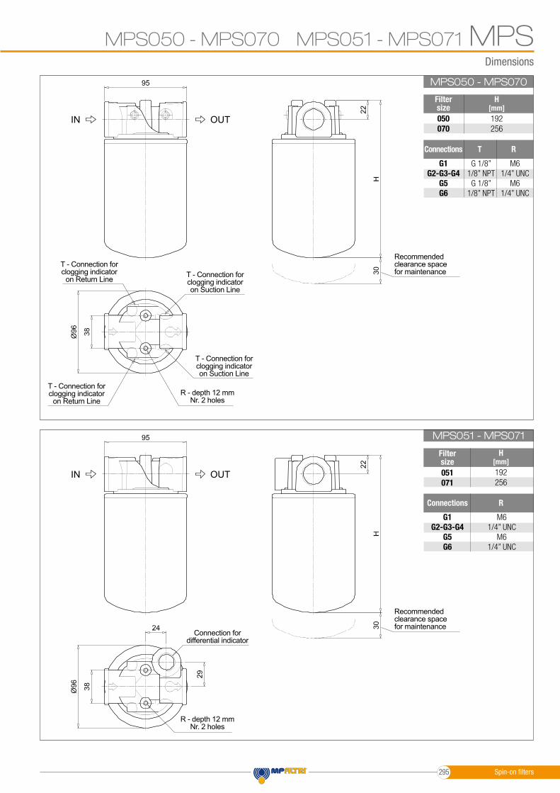
MPS050 - MPS070 MPS051 - MPS071 MPSMPS050 - MPS070
MPS051 - MPS071
Filter size
Filter size
Connections
Connections
H[mm]
H[mm]
R
R
T
050070
051071
G1 G2-G3-G4
G5G6
G1 G2-G3-G4
G5G6
192256
192256
M61/4” UNC
M61/4” UNC
M61/4” UNC
M61/4” UNC
G 1/8”1/8” NPTG 1/8”
1/8” NPT
R - depth 12 mmNr. 2 holes
R - depth 12 mmNr. 2 holes
T - Connection for clogging indicatoron Suction Line
T - Connection for clogging indicatoron Suction Line
Connection fordifferential indicator
T - Connection for clogging indicator
on Return Line
T - Connection for clogging indicator
on Return Line
Recommendedclearance spacefor maintenance
Recommendedclearance spacefor maintenance
OUT
OUT
IN
IN
Spin-on filters295
Designation & Ordering code
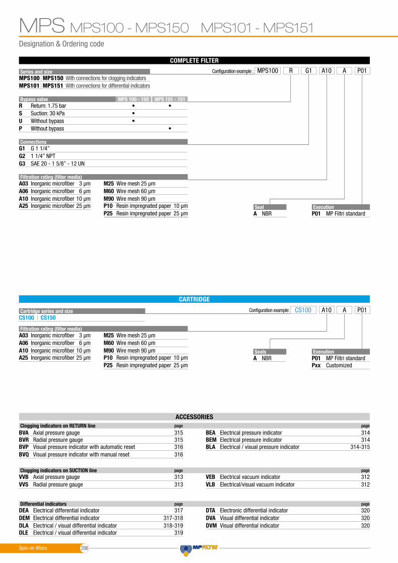
MPS100 - MPS150 MPS101 - MPS151MPS
CARTRIDGE
COMPLETE FILTER
Series and size
Cartridge series and size
Connections
Bypass valveR
G1
G3
SUP
G2
MPS 101 - 151MPS 100 - 150•••
•
•
G 1 1/4”
SAE 20 - 1 5/8” - 12 UN
With connections for clogging indicatorsWith connections for differential indicators
Configuration example:
MPS150MPS151
MPS100MPS101
CS100 CS150
Seal
Seals
A
A
NBR
NBR
Execution
Execution
P01
P01Pxx
MP Filtri standard
MP Filtri standardCustomized
1 1/4” NPT
Configuration example : MPS100 R AA10G1 P01
CS100 A10 A P01
Filtration rating (filter media)A03 M25
A10 M90A06 M60
A25 P10P25
Inorganic microfiber
Return: 1.75 barSuction: 30 kPaWithout bypassWithout bypass
Wire mesh3 µm 25 µm
Inorganic microfiber Wire mesh10 µm 90 µmInorganic microfiber Wire mesh6 µm 60 µm
Inorganic microfiber Resin impregnated paper25 µm 10 µmResin impregnated paper 25 µm
Filtration rating (filter media)A03 M25
A10 M90A06 M60
A25 P10P25
Inorganic microfiber Wire mesh3 µm 25 µm
Inorganic microfiber Wire mesh10 µm 90 µmInorganic microfiber Wire mesh6 µm 60 µm
Inorganic microfiber Resin impregnated paper25 µm 10 µmResin impregnated paper 25 µm
ACCESSORIES Clogging indicators on RETURN line page page
BVA
BVPBVR
BVQ
BEMBEA
BLA
Axial pressure gauge 315 314
Visual pressure indicator with automatic reset 316 314-315Radial pressure gauge 315 314
Visual pressure indicator with manual reset
Electrical pressure indicator
316
Electrical pressure indicator
Electrical / visual pressure indicator
Clogging indicators on SUCTION line page page
VVBVVS VLB
VEBAxial pressure gauge 313Radial pressure gauge 313 Electrical/visual vacuum indicator 312
Electrical vacuum indicator 312
Differential indicators page page
DEA
DLADEM
DLE
DVADTA
DVM
Electrical differential indicator 317
Electrical / visual differential indicator 318-319Electrical differential indicator 317-318
Electrical / visual differential indicator
Visual differential indicator
319
320Electronic differential indicator
Visual differential indicator
320
320
Spin-on filters 296

Dimensions
SF2500
SF2500
MPS100 - MPS150 MPS101 - MPS151 MPSMPS100 - MPS150
MPS101 - MPS151
Filter size
Filter size
Connections
Connections
H[mm]
H[mm]
R
R
T
100150
101151
G1 G2-G3
G1 G2-G3
246295
246295
M85/16” UNC
M85/16” UNC
G 1/8”1/8” NPT
R - depth 12 mmNr. 2 holes
R - depth 15 mmNr. 2 holes
T - Connection for clogging indicatoron Suction Line
T - Connection for clogging indicatoron Suction Line
Connection fordifferential indicator
T - Connection for clogging indicator
on Return Line
T - Connection for clogging indicatoron Return Line
Recommendedclearance spacefor maintenance
Recommendedclearance spacefor maintenance
OUT
OUT
IN
IN
Spin-on filters297

Designation & Ordering code
MPS200 - MPS250MPS
CARTRIDGE
COMPLETE FILTER
Series and size
Cartridge series and size
Connections
Bypass valveR
G1
G3
SU
G2G 1 1/2”
SAE 24 - 1 7/8” - 12 UN
Configuration example:
MPS250MPS200
CS100 CS150
Seal
Seals
A
A
NBR
NBR
Execution
Execution
P01
P01Pxx
MP Filtri standard
MP Filtri standardCustomized
1 1/2” NPT
Configuration example : MPS200 R AA10G1 P01
CS100 A10 A P01
Filtration rating (filter media)A03 M25
A10 M90A06 M60
A25 P10P25
Inorganic microfiber
Return: 1.75 barSuction: 30 kPaWithout bypass
Wire mesh3 µm 25 µm
Inorganic microfiber Wire mesh10 µm 90 µmInorganic microfiber Wire mesh6 µm 60 µm
Inorganic microfiber Resin impregnated paper25 µm 10 µmResin impregnated paper 25 µm
Filtration rating (filter media)A03 M25
A10 M90A06 M60
A25 P10P25
Inorganic microfiber Wire mesh3 µm 25 µm
Inorganic microfiber Wire mesh10 µm 90 µmInorganic microfiber Wire mesh6 µm 60 µm
Inorganic microfiber Resin impregnated paper25 µm 10 µmResin impregnated paper 25 µm
ACCESSORIES Clogging indicators on RETURN line page page
BVA
BVPBVR
BVQ
BEMBEA
BLA
Axial pressure gauge 315 314
Visual pressure indicator with automatic reset 316 314-315Radial pressure gauge 315 314
Visual pressure indicator with manual reset
Electrical pressure indicator
316
Electrical pressure indicator
Electrical / visual pressure indicator
Clogging indicators on SUCTION line page page
VVBVVS VLB
VEBAxial pressure gauge 313Radial pressure gauge 313 Electrical/visual vacuum indicator 312
Electrical vacuum indicator 312
Spin-on filters 298

Dimensions
SF2500
MPS200 - MPS250 MPSMPS200 - MPS250
Filter size
Connections
H[mm]
RT
200250
G1 G2-G3
213262
M107/16” UNC
G 1/8”1/8” NPT
R - depth 20 mmNr. 2 holes
T - Connection for clogging indicatoron Suction Line
T - Connection for clogging indicator
on Return Line
Recommendedclearance spacefor maintenance
Recommendedclearance spacefor maintenance
OUTIN
Spin-on filters299

Designation & Ordering code
MPS300 - MPS350 MPS301 - MPS351MPS
CARTRIDGE
COMPLETE FILTER
Series and size
Cartridge series and size
Connections
Bypass valveR
G1
F1G3
SUP
G2
F2
MPS 301 - 351MPS 300 - 350•••
•
•
G 1 1/2”
1 1/2” SAE 3000 psi/MSAE 24 - 1 7/8” - 12 UN
With connections for clogging indicatorsWith connections for differential indicators
Configuration example:
MPS350MPS351
MPS300MPS301
CS100 CS150
Seal
Seals
A
A
NBR
NBR
Execution
Execution
P01
P01Pxx
MP Filtri standard
MP Filtri standardCustomized
1 1/2” NPT
1 1/2” SAE 3000 psi/UNC
Configuration example : MPS300 R AA10F1 P01
CS100 A10 A P01
Filtration rating (filter media)A03 M25
A10 M90A06 M60
A25 P10P25
Inorganic microfiber
Return: 1.75 barSuction: 30 kPaWithout bypassWithout bypass
Wire mesh3 µm 25 µm
Inorganic microfiber Wire mesh10 µm 90 µmInorganic microfiber Wire mesh6 µm 60 µm
Inorganic microfiber Resin impregnated paper25 µm 10 µmResin impregnated paper 25 µm
Filtration rating (filter media)A03 M25
A10 M90A06 M60
A25 P10P25
Inorganic microfiber Wire mesh3 µm 25 µm
Inorganic microfiber Wire mesh10 µm 90 µmInorganic microfiber Wire mesh6 µm 60 µm
Inorganic microfiber Resin impregnated paper25 µm 10 µmResin impregnated paper 25 µm
ACCESSORIES Clogging indicators on RETURN line page page
BVA
BVPBVR
BVQ
BEMBEA
BLA
Axial pressure gauge 315 314
Visual pressure indicator with automatic reset 316 314-315Radial pressure gauge 315 314
Visual pressure indicator with manual reset
Electrical pressure indicator
316
Electrical pressure indicator
Electrical / visual pressure indicator
Clogging indicators on SUCTION line page page
VVBVVS VLB
VEBAxial pressure gauge 313Radial pressure gauge 313 Electrical/visual vacuum indicator 312
Electrical vacuum indicator 312
Differential indicators page page
DEA
DLADEM
DLE
DVADTA
DVM
Electrical differential indicator 317
Electrical / visual differential indicator 318-319Electrical differential indicator 317-318
Electrical / visual differential indicator
Visual differential indicator
319
320Electronic differential indicator
Visual differential indicator
320
320
Spin-on filters 300
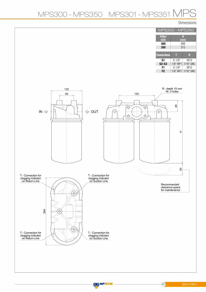
Dimensions
MPS300 - MPS350 MPS301 - MPS351 MPSSF2500MPS300 - MPS350
Filter size300350
266315
G1 G2-G3
F1F2
M107/16” UNC
M107/16” UNC
G 1/8”1/8” NPTG 1/8”
1/8” NPT
Connections
H[mm]
RT
R - depth 15 mmNr. 3 holes
T - Connection for clogging indicatoron Suction Line
T - Connection for clogging indicatoron Suction Line
T - Connection for clogging indicator
on Return Line
T - Connection for clogging indicator
on Return LineRecommendedclearance spacefor maintenance
OUTIN
Spin-on filters301

Dimensions
MPSSF2500MPS301 - MPS351
Filter size301351
266315
G1 G2-G3
F1F2
Connections
H[mm]
M107/16” UNC
M107/16” UNC
R
MPS300 - MPS350 MPS301 - MPS351
R - depth 15 mmNr. 3 holes
Recommendedclearance spacefor maintenance
OUTIN
Connection for differential indicatorT2 plug not included
Spin-on filters 302

MPS
Spin-on filters303

Spin-on filters 304
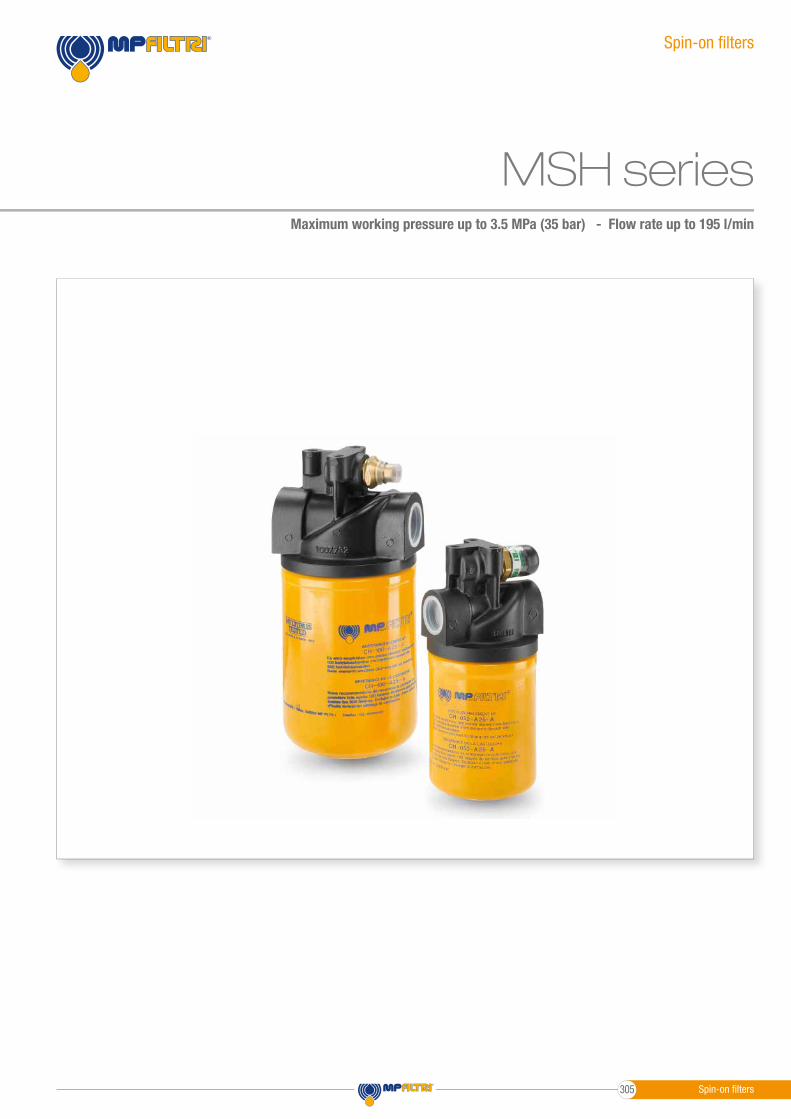
MSH seriesMaximum working pressure up to 3.5 MPa (35 bar) - Flow rate up to 195 l/min
Spin-on fi lters
Spin-on fi lters305

GENERAL INFORMATIONMSH
- Head: Anodized Aluminium- Bypass valve: Nylon - Steel- Element: Aluminium - Painted Steel
Filter housing materials
From -20 °C to +110 °CTemperature
Opening pressure: 250 kPa (2.5 bar) ±10%Bypass valve
- ∆p: 5 bar- Oil fl ow from OUT to IN
∆p element type
- Standard NBR - series A- Optional FPM - series V
Seals
MSH fi lters are provided for vertical mounting
Note
Cartridge
CH 050 - 070
CH 100 - 150
TypeM32 x 2
M45 x 2
ConnectionThread connections
CH
Weights [kg] and volumes [dm3]
1.501.903.303.80
Weights [kg]
MSH 050MSH 070MSH 100MSH 150
0.650.951.802.20
Volumes [dm3] Filter series
Spin-on fi lters
Maximum working pressure up to 3.5 MPa (35 bar)Flow rate up to 195 l/min
MSH is a range of spin-on fi lters suitable to be used in low pressure lines.They offer a good balance between performances, dimensions and prices.They are directly connected to the lines of the system through the hydraulic fi ttings.
Available features:- Female threaded connections up to 1 1/4”, for a maximum fl ow rate of 195 l/min- Fine fi ltration rating, to get a good cleanliness level into the reservoir- Strong sealing between the housing and cans, to be used in heavy applications- Bypass valve, to relieve excessive pressure drop across the fi lter media- Visual, electrical and electronic differential clogging indicators for low pressure applications
Common applications:- Delivery lines, in economic industrial equipment or mobile machines
Description Technical data
Spin-on fi lters 306
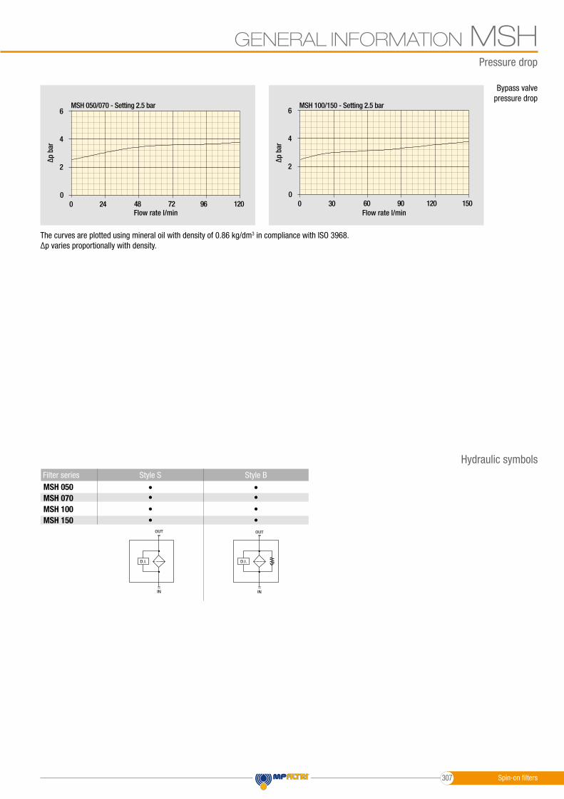
GENERAL INFORMATION MSH
6
4
2
00 24 48 72 96 120
6
4
2
00 30 60 90 120 150
6
4
2
00 24 48 72 96 120
6
4
2
00 30 60 90 120 150
The curves are plotted using mineral oil with density of 0.86 kg/dm3 in compliance with ISO 3968. ∆p varies proportionally with density.
Pressure drop
Bypass valve pressure drop
MSH 050MSH 070MSH 100MSH 150
Flow rate l/min Flow rate l/min
MSH 050/070 - Setting 2.5 bar MSH 100/150 - Setting 2.5 bar
∆p b
ar
∆p b
ar
Style BStyle S Filter series
• •• •••
••
D.I.
OUT
IN
D.I.
OUT
IN
Hydraulic symbols
Spin-on filters307
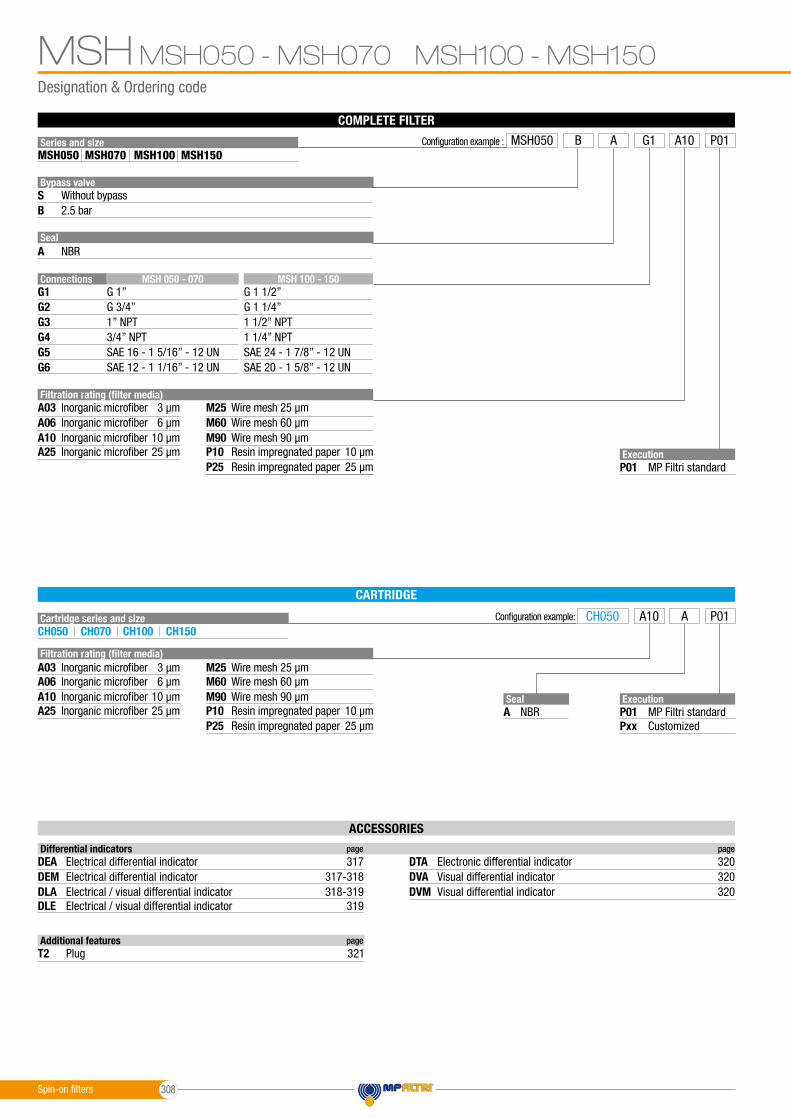
Designation & Ordering code
MSH050 - MSH070 MSH100 - MSH150MSH
CARTRIDGE
COMPLETE FILTER
Series and size
Cartridge series and size
Connections
Bypass valve
Seal
S
A
G1
G4G3
G6
B
G2
G5
G 1” G 1 1/2”
3/4” NPT 1 1/4” NPT1” NPT 1 1/2” NPT
SAE 12 - 1 1/16” - 12 UN SAE 20 - 1 5/8” - 12 UN
Configuration example:
MSH070 MSH150MSH050 MSH100
CH050 CH100CH070 CH150
SealA NBR
Execution
Execution
P01
P01Pxx
MP Filtri standard
MP Filtri standardCustomized
G 3/4” G 1 1/4”
SAE 16 - 1 5/16” - 12 UN SAE 24 - 1 7/8” - 12 UN
ACCESSORIES
Configuration example : MSH050 B A10G1A P01
CH050 A10 A P01
Filtration rating (filter media)A03 M25
A10 M90A06 M60
A25 P10P25
Inorganic microfiber
Without bypass
NBR
2.5 bar
Wire mesh3 µm 25 µm
Inorganic microfiber Wire mesh10 µm 90 µmInorganic microfiber Wire mesh6 µm 60 µm
Inorganic microfiber Resin impregnated paper25 µm 10 µmResin impregnated paper 25 µm
Filtration rating (filter media)A03 M25
A10 M90A06 M60
A25 P10P25
Inorganic microfiber Wire mesh3 µm 25 µm
Inorganic microfiber Wire mesh10 µm 90 µmInorganic microfiber Wire mesh6 µm 60 µm
Inorganic microfiber Resin impregnated paper25 µm 10 µmResin impregnated paper 25 µm
MSH 100 - 150MSH 050 - 070
Additional features page
T2 Plug 321
Differential indicators page page
DEA
DLADEM
DLE
DVADTA
DVM
Electrical differential indicator 317
Electrical / visual differential indicator 318-319Electrical differential indicator 317-318
Electrical / visual differential indicator
Visual differential indicator
319
320Electronic differential indicator
Visual differential indicator
320
320
Spin-on filters 308
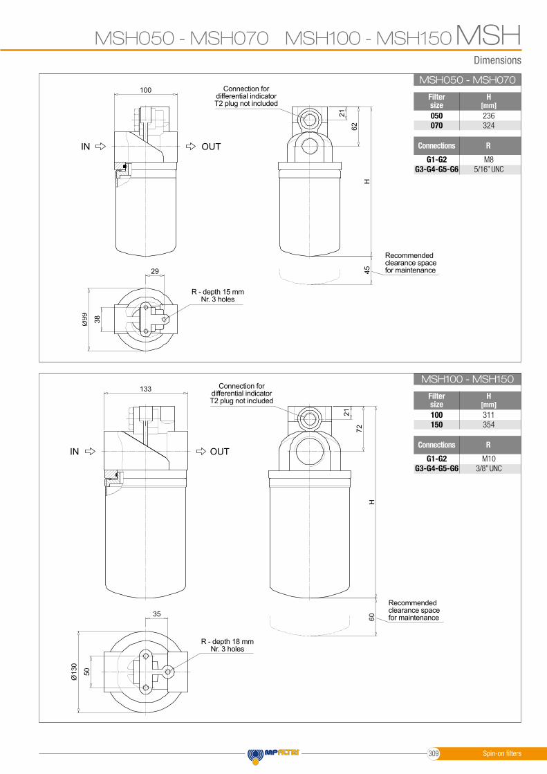
Dimensions
SF2500
SF2500
MSH050 - MSH070 MSH100 - MSH150 MSHMSH050 - MSH070
MSH100 - MSH150
Filter size
Filter size
Connections
Connections
H[mm]
H[mm]
R
R
050070
100150
G1-G2 G3-G4-G5-G6
G1-G2 G3-G4-G5-G6
236324
311354
M85/16” UNC
M103/8” UNC
R - depth 15 mmNr. 3 holes
R - depth 18 mmNr. 3 holes
Recommendedclearance spacefor maintenance
Recommendedclearance spacefor maintenance
OUT
OUT
IN
IN
Connection for differential indicatorT2 plug not included
Connection for differential indicatorT2 plug not included
Spin-on filters309
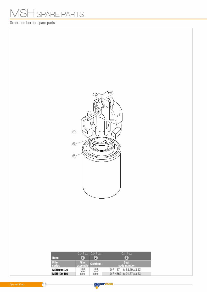
Order number for spare parts
SPARE PARTSMSH
1
2
3
Item:
Filter series
Seal code numberCartridgeFilter
assemblyO-R 167 (ø 63.50 x 3.53)O-R 4362 (ø 91.67 x 3.53)
Seeorder table
Seeorder table
21
MSH 050-070MSH 100-150
Q.ty: 1 pc.Q.ty: 1 pc.Q.ty: 1 pc.3
Spin-on fi lters 310
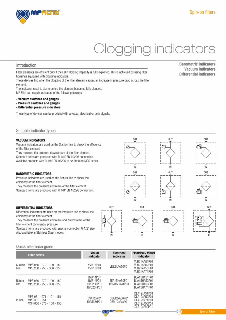
Spin-on filters
Clogging indicatorsBarometric indicators
Vacuum indicatorsDifferential indicators
Introduction
- Vacuum switches and gauges- Pressure switches and gauges- Differential pressure indicators
Filter elements are efficient only if their Dirt Holding Capacity is fully exploited. This is achieved by using filter housings equipped with clogging indicators.These devices trip when the clogging of the filter element causes an increase in pressure drop across the filter element.The indicator is set to alarm before the element becomes fully clogged.MP Filtri can supply indicators of the following designs:
These type of devices can be provided with a visual, electrical or both signals.
BAROMETRIC INDICATORSPressure indicators are used on the Return line to check the efficiency of the filter element.They measure the pressure upstream of the filter element.Standard items are produced with R 1/8” EN 10226 connection.
23
1
IN
OUT
IN
OUT
IN
OUT
IN
OUT
IN
OUT
IN
OUT
IN
OUT
IN
OUT
IN
OUT
IN
OUT
23
1
23
123
1
2
31
2
31
2
31
DIFFERENTIAL INDICATORSDifferential indicators are used on the Pressure line to check the efficiency of the filter element.They measure the pressure upstream and downstream of the filter element (differential pressure).Standard items are produced with special connection G 1/2” size.Also available in Stainless Steel models.
23
1
IN
OUT
IN
OUT
IN
OUT
IN
OUT
IN
OUT
IN
OUT
IN
OUT
IN
OUT
IN
OUT
IN
OUT
23
1
23
123
1
2
31
2
31
2
31
Suitable indicator types
VACUUM INDICATORSVacuum indicators are used on the Suction line to check the efficiency of the filter element.They measure the pressure downstream of the filter element.Standard items are produced with R 1/4” EN 10226 connection.Available products with R 1/8” EN 10226 to be fitted on MPS series.
23
1
IN
OUT
IN
OUT
IN
OUT
IN
OUT
IN
OUT
IN
OUT
IN
OUT
IN
OUT
IN
OUT
IN
OUT
23
1
23
123
1
2
31
2
31
2
31
Quick reference guide
MPS 050 - 070 - 100 - 150MPS 200 - 250 - 300 - 350
Suctionline
MPS 050 - 070 - 100 - 150MPS 200 - 250 - 300 - 350
Returnline
MPS 051 - 071 - 101 - 151MPS 301 - 351MSH 050 - 070 - 100 - 150
In-line
VLB21AA51P01VLB21AA52P01VLB21AA53P01VLB21AA71P01
BLA15HA51P01BLA15HA52P01BLA15HA53P01BLA15HA71P01
DLA12xA51P01DLA12xA52P01DLA12xA71P01DLE12xA50P01DLE12xF50P01
VVB16P01VVS16P01
BVA14P01BVR14P01
BVP20HP01BVQ20HP01
DVA12xP01DVM12xP01
VEB21AA50P01
BEA15HA50P01BEM15HA41P01
DEA12xA50P01DEM12xAxxP01
Filter seriesVisual
indicatorElectricalindicator
Electrical / Visualindicator
Spin-on filters311

VACUUM INDICATORSDimensions
1
2
3
4
GREENLAMP
REDLAMP
GREENLAMP
REDLAMP
1
2
3
1
2
3
4
5
R R R
1277
1277
1273
1
2
3
4
GREENLAMP
REDLAMP
GREENLAMP
REDLAMP
1
2
3
1
2
3
4
5
R R R
1277
1277
1273
1
2
3
4
GREENLAMP
REDLAMP
GREENLAMP
REDLAMP
1
2
3
1
2
3
4
5
R R R
1277
1277
1273
1
2
3
4
GREENLAMP
REDLAMP
GREENLAMP
REDLAMP
1
2
3
1
2
3
4
5
R R R
1277
1277
1273
1
2
3
4
GREENLAMP
REDLAMP
GREENLAMP
REDLAMP
1
2
3
1
2
3
4
5
R R R
1277
1277
1273
1
2
3
4
GREENLAMP
REDLAMP
GREENLAMP
REDLAMP
1
2
3
1
2
3
4
5
R R R
1277
1277
1273
Electrical Vacuum Indicator
Electrical/Visual Vacuum Indicator
Electrical/Visual Vacuum Indicator
VE B 21 A A 50 P01
VL B 21 A A xx P01
VL B 21 A A 71 P01
EN 10226 - R1/8”
EN 10226 - R1/8”
EN 10226 - R1/8”
R
R
Connections
Ordering code
Ordering code
Ordering code
Hydraulic symbol
Hydraulic symbol
Hydraulic symbol
Electrical symbol
Electrical symbol
Electrical symbol
Materials- Body: Brass- Base: Black Nylon- Contacts: Silver- Seal: NBR
Technical data- Vacuum setting: -0.21 bar ±10%- Max working pressure: 10 bar- Proof pressure: 15 bar- Working temperature: From -25 °C to +80 °C- Compatibility with fluids: Mineral oils, Synthetic fluids HFA, HFB, HFC according to ISO 2943- Degree of protection: IP65 according to EN 60529
Electrical data- Electrical connection: EN 175301-803- Resistive load: 5 A / 14 Vdc 4 A / 30 Vdc 5 A / 125 Vac 4 A / 250 Vac- Available Atex product: II 1GD Ex ia IIC Tx Ex ia IIIC Tx°C X- CE certification
Materials- Body: Brass- Base: Transparent Nylon- Contacts: Brass - Nylon- Seal: NBR
Technical data- Vacuum setting: -0.21 bar ±10%- Max working pressure: 10 bar- Proof pressure: 15 bar- Working temperature: From -25 °C to +80 °C- Compatibility with fluids: Mineral oils, Synthetic fluids HFA, HFB, HFC according to ISO 2943- Degree of protection: IP65 according to EN 60529
Electrical data- Electrical connection: EN 175301-803- Type 51 52 53- Lamps 24 Vdc 110 Vdc 230 Vac- Resistive load: 1 A / 24 Vdc 1 A / 110 Vdc 1 A / 230 Vac
Materials- Body: Brass- Base: Black Nylon- Contacts: Silver- Seal: NBR
Technical data- Vacuum setting: -0.21 bar ±10%- Max working pressure: 10 bar- Proof pressure: 15 bar- Working temperature: From -25 °C to +80 °C- Compatibility with fluids: Mineral oils, Synthetic fluids HFA, HFB, HFC according to ISO 2943- Degree of protection: IP65 according to EN 60529
Electrical data- Electrical connection: IEC 61076-2-101 D (M12)- Lamps 24 Vdc- Resistive load: 0.4 A / 24 Vdc
VE*50
VL*51 - VL*52 - VL*53
VL*71
1
2
3
1
2
3
1
2
3
1
2
3
4
5
1 2
1
2
3
1
2
3
1
2
3
1
2
3
4
5
1 2
1
2
3
1
2
3
1
2
3
1
2
3
4
5
1 2
A/F 27Max tighteningtorque: 25 N∙m
A/F 27Max tighteningtorque: 25 N∙m
A/F 27Max tighteningtorque: 25 N∙m
GREENLAMP
GREENLAMP
REDLAMP
REDLAMP
Spin-on filters 312
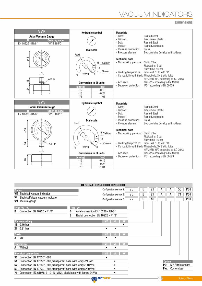
-0.16-0.24-1.01
-0.16-0.24-1.01
-12-18-76
-12-18-76
[cmHg]
[cmHg]
[bar]
[bar]
VACUUM INDICATORSDimensions
SeriesVEVLVV
OptionP01Pxx
MP Filtri standardCustomized
Configuration example 1: V E AB 50A21 P01
Configuration example 2: V L AB 71A21 P01Configuration example 3: V V S 16 P01
Type VE - VL Type VV
Electrical connections50
52
B B
51
S
5371
Vacuum setting
2116
VL
VL
VL
VL
VV
VV
VV
VV
VE
VE
VE
VE
0.21 bar
Electrical vacuum indicator
Connection EN 175301-803
Vacuum gaugeElectrical/Visual vacuum indicator
Connection EN 10226 - R1/8” Axial connection EN 10226 - R1/8”
Connection EN 175301-803, transparent base with lamps 110 VdcConnection EN 175301-803, transparent base with lamps 24 Vdc
Connection EN 175301-803, transparent base with lamps 230 VdcConnection IEC 61076-2-101 D (M12), black base with lamps 24 Vdc
Radial connection EN 10226 - R1/8”
0.16 bar
DESIGNATION & ORDERING CODE
Seals
Thermostat
Axial Vacuum Gauge
A
Radial Vacuum Gauge
A
NBR
Without
V V B
V V S
R
A/F 14
R
ø43
1824
2818
ø53
R
A/F 14
R
ø43
1824
2818
ø53
R
A/F 14
R
ø43
1824
2818
ø53
R
A/F 14
R
ø43
1824
2818
ø53
••
•
•
•
•
•
••••
•
VV B 16 P01
VV S 16 P01
A/F 11
EN 10226 - R1/8”
EN 10226 - R1/8”
R
R
Ordering code
Ordering code
Hydraulic symbol
Hydraulic symbol
Dial scale
Dial scale
Conversion to SI units
Conversion to SI units
Materials- Case: Painted Steel- Window: Transparent plastic- Dial: Painted Steel- Pointer: Painted Aluminium- Pressure connection: Brass- Pressure element: Bourdon tube Cu-alloy soft soldered
Technical data- Max working pressure: Static: 7 bar Fluctuating: 6 bar Short time: 10 bar- Working temperature: From -40 °C to +60 °C- Compatibility with fluids: Mineral oils, Synthetic fluids HFA, HFB, HFC according to ISO 2943- Accuracy: Class 2.5 according to EN 13190- Degree of protection: IP31 according to EN 60529
1
2
3
1
2
3
1
2
3
1
2
3
4
5
1 2
1
2
3
1
2
3
1
2
3
1
2
3
4
5
1 2
Red
Red
Yellow
Yellow
Green
Green
cmHg
cmHg
Spin-on filters313

Electrical Pressure Indicator
Electrical Pressure Indicator
Electrical/Visual Pressure Indicator
BEA*50
BEM*41
BL*51 - BL*52 - BL*53
Materials- Body: Brass- Base: Black Nylon- Contacts: Silver- Seal: HNBR
Technical data- Max working pressure: 40 bar- Proof pressure: 60 bar- Working temperature: From -25 °C to +80 °C- Compatibility with fluids: Mineral oils, Synthetic fluids HFA, HFB, HFC according to ISO 2943- Degree of protection: IP65 according to EN 60529
Electrical data- Electrical connection: EN 175301-803- Resistive load: 5 A / 14 Vdc 4 A / 30 Vdc 5 A / 125 Vac 4 A / 250 Vac- Available Atex product: II 1GD Ex ia IIC Tx Ex ia IIIC Tx°C X- CE certification
Materials- Body: Brass- Base: Black Nylon- Contacts: Silver- Seal: HNBR
Technical data- Max working pressure: 40 bar- Proof pressure: 60 bar- Working temperature: From -25 °C to +80 °C- Compatibility with fluids: Mineral oils, Synthetic fluids HFA, HFB, HFC according to ISO 2943- Degree of protection: IP67 according to EN 60529
Electrical data- Electrical connection: Four-core cable- Resistive load: 5 A / 14 Vdc 4 A / 30 Vdc 5 A / 125 Vac 4 A / 250 Vac- CE certificationOn request this indicator can be provided with main connectors in use for wirings.
Materials- Body: Brass- Base: Transparent Nylon- Contacts: Silver- Seal: HNBR
Technical data- Max working pressure: 40 bar- Proof pressure: 60 bar- Working temperature: From -25 °C to +80 °C- Compatibility with fluids: Mineral oils, Synthetic fluids HFA, HFB, HFC according to ISO 2943- Degree of protection: IP65 according to EN 60529
Electrical data- Electrical connection: EN 175301-803- Type 51 52 53- Lamps 24 Vdc 110 Vdc 230 Vac- Resistive load: 1 A / 24 Vdc 1 A / 110 Vdc 1 A / 230 Vac
1
2
3
4
1
2
3
1
2
3
4
EN 10226 - R1/8”
7710
EN 10226 - R1/8”
7710
EN 10226 - R1/8”
7310
1
2
3
4
1
2
3
1
2
3
4
EN 10226 - R1/8”
7710
EN 10226 - R1/8”
7710
EN 10226 - R1/8”
7310
1
2
3
4
1
2
3
1
2
3
4
EN 10226 - R1/8”
7710
EN 10226 - R1/8”
7710
EN 10226 - R1/8”
7310
EN 10226 - R1/8”
GREY
BLACK
BROWN
YELLOW / GREEN
EN 10226 - R1/8”10
1455
7710
00
EN 10226 - R1/8”
GREY
BLACK
BROWN
YELLOW / GREEN
EN 10226 - R1/8”10
1455
7710
00
1
2
3
4
1
2
3
1
2
3
4
EN 10226 - R1/8”
7710
EN 10226 - R1/8”
7710
EN 10226 - R1/8”
7310
1
2
3
1
2
3
1
2
3
1
2
3
4
5
1 2
1
2
3
1
2
3
1
2
3
1
2
3
4
5
1 2
1
2
3
1
2
3
1
2
3
1
2
3
4
5
1 2
Hydraulic symbol
Hydraulic symbol
Hydraulic symbol
Electrical symbol
Electrical symbol
Electrical symbol
BE A 15 H A 50 P01BE A 20 H A 50 P01
BE M 15 H A 41 P01BE M 20 H A 41 P01
BL A 15 H A xx P01BL A 20 H A xx P01
1.5 bar ±10%2.0 bar ±10%
1.5 bar ±10%2.0 bar ±10%
1.5 bar ±10%2.0 bar ±10%
Settings
Settings
Settings
Ordering code
Ordering code
Ordering code
BAROMETRIC INDICATORSDimensions
A/F 27Max tighteningtorque: 25 N∙m
A/F 27Max tighteningtorque: 25 N∙m
A/F 27Max tighteningtorque: 25 N∙m
GREENLAMP
REDLAMP
Spin-on filters 314

BAROMETRIC INDICATORSDimensions
Electrical/Visual Pressure Indicator
Radial Pressure Gauge
BL*71
BVR
Materials- Body: Brass- Base: Black Nylon- Contacts: Silver- Seal: HNBR
Technical data- Max working pressure: 40 bar- Proof pressure: 60 bar- Working temperature: From -25 °C to +80 °C- Compatibility with fluids: Mineral oils, Synthetic fluids HFA, HFB, HFC according to ISO 2943- Degree of protection: IP65 according to EN 60529
Electrical data- Electrical connection: IEC 61076-2-101 D (M12)- Lamps: 24 Vdc- Resistive load: 0.4 A / 24 Vdc
Materials- Case: Painted Steel- Window: Transparent plastic- Dial: Painted Steel- Pointer: Painted Aluminium- Pressure connection: Brass- Pressure element: Bourdon tube Cu-alloy soft soldered
Technical data- Max working pressure: Static: 7 bar Fluctuating: 6 bar Short time: 10 bar- Working temperature: From -40 °C to +60 °C- Compatibility with fluids: Mineral oils, Synthetic fluids HFA, HFB, HFC according to ISO 2943- Accuracy: Class 2.5 according to EN 13190- Degree of protection: IP31 according to EN 60529
1
2
3
4
1
2
3
1
2
3
4
EN 10226 - R1/8”
7710
EN 10226 - R1/8”
7710
EN 10226 - R1/8”
7310
1
2
3
4
1
2
3
1
2
3
4
EN 10226 - R1/8”
7710
EN 10226 - R1/8”
7710
EN 10226 - R1/8”
7310
1
2
3
1
2
3
1
2
3
1
2
3
4
5
1 2
1
2
3
1
2
3
1
2
3
1
2
3
4
5
1 2
Hydraulic symbol
Electrical symbol
Hydraulic symbol
EN 10226 - R1/8”
A/F 11
EN 10226 - R1/8”
A/F 11
ø 43
ø 43
1525
2316
EN 10226 - R1/8”
A/F 11
EN 10226 - R1/8”
A/F 11
ø 43
ø 43
1525
2316
BL A 15 H A 71 P01BL A 20 H A 71 P01
BV R 14 P01BV R 25 P01
1.5 bar ±10%2.0 bar ±10%
1.4 bar ±10%2.5 bar ±10%
Settings
Settings
Ordering code
Ordering code
Axial Pressure Gauge
BVA Materials- Case: Painted Steel- Window: Transparent plastic- Dial: Painted Steel- Pointer: Painted Aluminium- Pressure connection: Brass- Pressure element: Bourdon tube Cu-alloy soft soldered
Technical data- Max working pressure: Static: 7 bar Fluctuating: 6 bar Short time: 10 bar- Working temperature: From -40 °C to +60 °C- Compatibility with fluids: Mineral oils, Synthetic fluids HFA, HFB, HFC according to ISO 2943- Accuracy: Class 2.5 according to EN 13190- Degree of protection: IP31 according to EN 60529
1
2
3
1
2
3
1
2
3
1
2
3
4
5
1 2
Hydraulic symbol
EN 10226 - R1/8”
A/F 11
EN 10226 - R1/8”
A/F 11
ø 43
ø 43
1525
2316
EN 10226 - R1/8”
A/F 11
EN 10226 - R1/8”
A/F 11
ø 43
ø 43
1525
2316
BV A 14 P01BV A 25 P01
BV A 14 P01
BV A 25 P01
1.4 bar ±10%2.5 bar ±10%
Settings Ordering code
A/F 27Max tighteningtorque: 25 N∙m
Dial scale
BV R 14 P01
BV R 25 P01
Dial scale
Red
Red
Red
Red
Yellow
Yellow
Yellow
Yellow
Green
Green
Green
Green
bar
bar
bar
bar
GREENLAMP
REDLAMP
Spin-on filters315
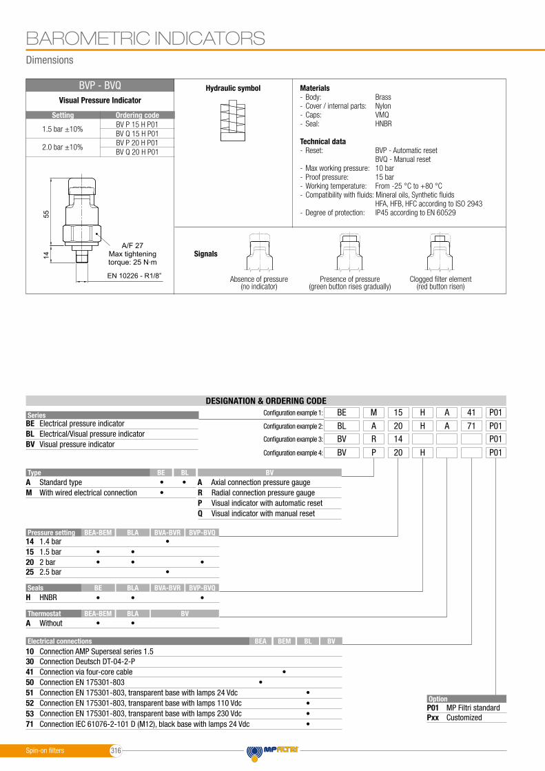
BAROMETRIC INDICATORSDimensions
SeriesBEBLBV
OptionP01Pxx
MP Filtri standardCustomized
Configuration example 1: BE HM 41A15 P01
Configuration example 2: BL HA 71A20 P01Configuration example 3: BV R 14 P01
Configuration example 4: BV H P 20 P01
TypeA A
RMPQ
Standard type Axial connection pressure gauge
Electrical pressure indicator
Radial connection pressure gauge
Visual pressure indicator
With wired electrical connection
Electrical/Visual pressure indicator
Visual indicator with automatic resetVisual indicator with manual reset
DESIGNATION & ORDERING CODE
••
•
Electrical connections
3010
5041
51
5352
71
BEA BEM BL BV
BE BL BV
Connection Deutsch DT-04-2-PConnection AMP Superseal series 1.5
Connection via four-core cable ••
••
••
Visual Pressure Indicator
BVP - BVQ
EN 10226 - R1/8”
GREY
BLACK
BROWN
YELLOW / GREEN
EN 10226 - R1/8”10
1455
7710
00
EN 10226 - R1/8”
GREY
BLACK
BROWN
YELLOW / GREEN
EN 10226 - R1/8”10
1455
7710
00 1
2
3
1
2
3
1
2
3
1
2
3
4
5
1 2
Materials- Body: Brass- Cover / internal parts: Nylon- Caps: VMQ- Seal: HNBR
Technical data- Reset: BVP - Automatic reset BVQ - Manual reset- Max working pressure: 10 bar- Proof pressure: 15 bar- Working temperature: From -25 °C to +80 °C- Compatibility with fluids: Mineral oils, Synthetic fluids HFA, HFB, HFC according to ISO 2943- Degree of protection: IP45 according to EN 60529
Absence of pressure(no indicator)
Presence of pressure(green button rises gradually)
Clogged filter element(red button risen)
Signals
Hydraulic symbol
Connection EN 175301-803
Connection EN 175301-803, transparent base with lamps 110 VdcConnection EN 175301-803, transparent base with lamps 24 Vdc
Connection EN 175301-803, transparent base with lamps 230 VdcConnection IEC 61076-2-101 D (M12), black base with lamps 24 Vdc
BV P 15 H P01BV Q 15 H P01BV P 20 H P01BV Q 20 H P01
1.5 bar ±10%
2.0 bar ±10%
Setting Ordering code
A/F 27Max tighteningtorque: 25 N∙m
Pressure setting14
2015
25
1.4 bar
2 bar1.5 bar
2.5 bar
Seals
Thermostat
H
A
HNBR
Without
•• •• • •
•
BEA-BEM
BEA-BEM
BE
BLA
BLA
BLA
BVA-BVR
BVA-BVR
BVP-BVQ
BV
BVP-BVQ
•
•
•
• •
Spin-on filters 316

DE A 12 x A 50 P01DE A 20 x A 50 P01
DE M 12 x x 10 P01DE M 20 x x 10 P01
DE M 12 x x 20 P01DE M 20 x x 20 P01
1.2 bar ±10%2.0 bar ±10%
1.2 bar ±10%2.0 bar ±10%
1.2 bar ±10%2.0 bar ±10%
Settings
Settings
Settings
Ordering code
Ordering code
Ordering code
Dimensions
DIFFERENTIAL INDICATORS
1
2
1
2
1
2A
C
B
60
75
Electrical Differential Indicator
Electrical Differential Indicator
Electrical Differential Indicator
DEA*50
DEM*10
DEM*20
Materials- Body: Brass- Base: Black Nylon- Contacts: Silver- Seal: HNBR - FPM
Technical data- Max working pressure: 420 bar- Proof pressure: 630 bar- Burst pressure: 1260 bar- Working temperature: From -25 °C to +110 °C- Compatibility with fluids: Mineral oils, Synthetic fluids HFA, HFB, HFC according to ISO 2943- Degree protection: IP66 according to EN 60529 IP69K according to ISO 20653
Electrical data- Electrical connection: EN 175301-803- Resistive load: 0.2 A / 115 Vdc
Materials- Body: Brass- Base: Black Nylon- Contacts: Silver- Seal: HNBR - FPM
Technical data- Max working pressure: 420 bar- Proof pressure: 630 bar- Burst pressure: 1260 bar- Working temperature: From -25 °C to +110 °C- Compatibility with fluids: Mineral oils, Synthetic fluids HFA, HFB, HFC according to ISO 2943- Degree protection: IP66 according to EN 60529
Electrical data- Electrical connection: AMP Superseal series 1.5- Resistive load: 0.2 A / 115 Vdc- Switching type: Normally open contacts (NC on request)- Thermal lockout: Normally open up to 30 °C (option “F”)
Materials- Body: Brass- Base: Black Nylon- Contacts: Silver- Seal: HNBR - FPM
Technical data- Max working pressure: 420 bar- Proof pressure: 630 bar- Burst pressure: 1260 bar- Working temperature: From -25 °C to +110 °C- Compatibility with fluids: Mineral oils, Synthetic fluids HFA, HFB, HFC according to ISO 2943- Degree protection: IP66 according to EN 60529
Electrical data- Electrical connection: AMP Time junior- Resistive load: 0.2 A / 115 Vdc- Switching type: Normally open contacts (NC on request)- Thermal lockout: Normally open up to 30 °C (option “F”)
1
2
3
1
2
3
1
2
3
1
2
3
4
5
1 2
1
2
3
1
2
3
1
2
3
1
2
3
4
5
1 2
1
2
3
1
2
3
1
2
3
1
2
3
4
5
1 2
Hydraulic symbol
Hydraulic symbol
Hydraulic symbol
Electrical symbol
Electrical symbol
Electrical symbol
3
2
1
3
2
1
3
1
2
5
44
505353
3
2
1
3
2
1
3
1
2
5
44
505353
1
2
1
2
1
2A
C
B
60
75
1
2
1
2
1
2A
C
B
60
75
1
2
1
2
1
2A
C
B
60
75
A/F 30Max tighteningtorque: 65 N∙m
A/F 28Max tighteningtorque: 65 N∙m
A/F 28Max tighteningtorque: 65 N∙m
flexi
ble
cabl
e: 2
90 to
“A” Thermal lockout
Thermal lockout
Spin-on filters317

DE M 12 x x 30 P01DE M 20 x x 30 P01
DE M 12 x x 35 P01DE M 20 x x 35 P01
DL A 12 x A xx P01DL A 20 x A xx P01
1.2 bar ±10%2.0 bar ±10%
1.2 bar ±10%2.0 bar ±10%
1.2 bar ±10%2.0 bar ±10%
Settings
Settings
Settings
Ordering code
Ordering code
Ordering code
1
2
1
2
1
2A
C
B
60
75
1
2
1
2
1
2A
C
B
60
75
3
2
1
3
2
1
3
1
2
5
44
505353
DIFFERENTIAL INDICATORSDimensions
Electrical Differential Indicator
Electrical Differential Indicator
Electrical/Visual Differential Indicator
DEM*30
DEM*35
DLA*51 - DLA*52
Materials- Body: Brass- Base: Black Nylon- Contacts: Silver- Seal: HNBR - FPM
Technical data- Max working pressure: 420 bar- Proof pressure: 630 bar- Burst pressure: 1260 bar- Working temperature: From -25 °C to +110 °C- Compatibility with fluids: Mineral oils, Synthetic fluids HFA, HFB, HFC according to ISO 2943- Degree protection: IP66 according to EN 60529
Electrical data- Electrical connection: Deutsch DT-04-2-P- Resistive load: 0.2 A / 115 Vdc- Switching type: Normally open contacts (NC on request)- Thermal lockout: Normally open up to 30 °C (option “F”)
Materials- Body: Brass- Base: Black Nylon- Contacts: Silver- Seal: HNBR - FPM
Technical data- Max working pressure: 420 bar- Proof pressure: 630 bar- Burst pressure: 1260 bar- Working temperature: From -25 °C to +110 °C- Compatibility with fluids: Mineral oils, Synthetic fluids HFA, HFB, HFC according to ISO 2943- Degree protection: IP66 according to EN 60529
Electrical data- Electrical connection: Deutsch DT-04-3-P- Resistive load: 0.2 A / 115 Vdc- Switching type: SPDT contact- Thermal lockout: Normally open up to 30 °C (option “F”)
Materials- Body: Brass- Base: Transparent Nylon- Contacts: Silver- Seal: HNBR - FPM
Technical data- Max working pressure: 420 bar- Proof pressure: 630 bar- Burst pressure: 1260 bar- Working temperature: From -25 °C to +110 °C- Compatibility with fluids: Mineral oils, Synthetic fluids HFA, HFB, HFC according to ISO 2943- Degree protection: IP66 according to EN 60529 IP69K according to ISO 20653
Electrical data- Electrical connection: EN 175301-803- Type 51 52 - Lamps 24 Vdc 110 Vdc - Resistive load: 1 A / 24 Vdc 1 A / 110 Vdc
1
2
3
1
2
3
1
2
3
1
2
3
4
5
1 2
1
2
3
1
2
3
1
2
3
1
2
3
4
5
1 2
1
2
3
1
2
3
1
2
3
1
2
3
4
5
1 2
Hydraulic symbol
Hydraulic symbol
Hydraulic symbol
Electrical symbol
Electrical symbol
Electrical symbol
3
2
1
3
2
1
3
1
2
5
44
505353
1
2
1
2
1
2A
C
B
60
75
1
2
1
2
1
2A
C
B
60
75
A/F 28Max tighteningtorque: 65 N∙m
A/F 28Max tighteningtorque: 65 N∙m
flexi
ble
cabl
e: 2
40 to
“A”
A/F 30Max tighteningtorque: 65 N∙m
Thermal lockout
Thermal lockout
GREENLAMP
REDLAMP
Spin-on filters 318

DIFFERENTIAL INDICATORSDimensions
DL A 12 x A 71 P01DL A 20 x A 71 P01
1.2 bar ±10%2.0 bar ±10%
Settings Ordering code
DL E 12 x A 50 P01DL E 20 x A 50 P01
1.2 bar ±10%2.0 bar ±10%
Settings Ordering code
DL E 12 x F 50 P01DL E 20 x F 50 P01
1.2 bar ±10%2.0 bar ±10%
Settings Ordering code
Electrical/Visual Differential Indicator
Electrical/Visual Differential Indicator
Electrical/Visual Differential Indicator
DLA*71
DLE*A50
DLE*F50
Materials- Body: Brass- Base: Black Nylon- Contacts: Silver- Seal: HNBR - FPM
Technical data- Max working pressure: 420 bar- Proof pressure: 630 bar- Burst pressure: 1260 bar- Working temperature: From -25 °C to +110 °C- Compatibility with fluids: Mineral oils, Synthetic fluids HFA, HFB, HFC according to ISO 2943- Degree protection: IP65 according to EN 60529 IP69K according to ISO 20653
Electrical data- Electrical connection: IEC 61076-2-101 D (M12)- Lamps 24 Vdc- Resistive load: 0.4 A / 24 Vdc
Materials- Body: Brass- Base: Black Nylon- Contacts: Silver- Seal: HNBR - FPM
Technical data- Max working pressure: 420 bar- Proof pressure: 630 bar- Burst pressure: 1260 bar- Working temperature: From -25 °C to +110 °C- Compatibility with fluids: Mineral oils, Synthetic fluids HFA, HFB, HFC according to ISO 2943- Degree protection: IP65 according to EN 60529
Electrical data- Electrical connections: EN 175301-803- Resistive load: 5 A / 250 Vac- Available the connector with lamps
Materials- Body: Brass- Base: Black Nylon- Contacts: Silver- Seal: HNBR - FPM
Technical data- Max working pressure: 420 bar- Proof pressure: 630 bar- Burst pressure: 1260 bar- Working temperature: From -25 °C to +110 °C- Compatibility with fluids: Mineral oils, Synthetic fluids HFA, HFB, HFC according to ISO 2943- Degree protection: IP65 according to EN 60529
Electrical data- Electrical connections: EN 175301-803- Resistive load: 5 A / 250 Vac- Thermal lockout setting: +30 °C
Hydraulic symbol
Hydraulic symbol
Hydraulic symbol
Electrical symbol
Electrical symbol
Electrical symbol
3
2
1
3
2
1
3
1
2
5
44
505353
1
2
3
1
2
3
58
58
58
59
1
2
3
1
2
3
58
58
58
59
1
2
3
1
2
3
1
2
3
1
2
3
4
5
1 2
1
2
3
1
2
3
1
2
3
1
2
3
4
5
1 2
1
2
3
1
2
3
1
2
3
1
2
3
4
5
1 2
3
2
1
3
2
1
3
1
2
5
44
505353
1
2
3
1
2
3
58
58
58
59
1
2
3
1
2
3
58
58
58
59
A/F 30Max tighteningtorque: 65 N∙m
A/F 32Max tighteningtorque: 95 N∙m
A/F 32Max tighteningtorque: 95 N∙m
Thermal lockout
GREENLAMP
REDLAMP
Spin-on filters319

DT A 12 x x 70 P01DT A 20 x x 70 P01
1.2 bar ±10%2.0 bar ±10%
Settings Ordering code
DV A 12 x P01DV A 20 x P01
1.2 bar ±10%2.0 bar ±10%
Settings Ordering code
DV M 12 x P01DV M 20 x P01
1.2 bar ±10%2.0 bar ±10%
Settings Ordering code
Dimensions
Electronic Differential Indicator
Visual Differential Indicator
Visual Differential Indicator
DTA*70
DVA
DVM
Materials- Body: Brass- Internal parts: Brass - Nylon- Contacts: Silver- Seal: HNBR - FPM
Technical data- Max working pressure: 420 bar- Proof pressure: 630 bar- Burst pressure: 1260 bar- Compatibility with fluids: Mineral oils, Synthetic fluids HFA, HFB, HFC according to ISO 2943- Degree protection: IP67 according to EN 60529
Electrical data- Electrical connection: IEC 61076-2-101 D (M12)- Power supply: 24 Vdc- Analogue output: From 4 to 20 mA- Thermal lockout: 30 °C (all output signals stalled up to 30 °C)
Materials- Body: Brass- Internal parts: Brass - Nylon- Contacts: Silver- Seal: HNBR - FPM
Technical data- Reset: Automatic reset- Max working pressure: 420 bar- Proof pressure: 630 bar- Burst pressure: 1260 bar- Working temperature: From -25 °C to +110 °C- Compatibility with fluids: Mineral oils, Synthetic fluids HFA, HFB, HFC according to ISO 2943- Degree protection: IP65 according to EN 60529
Materials- Body: Brass- Internal parts: Brass - Nylon- Contacts: Silver- Seal: HNBR - FPM
Technical data- Reset: Manual reset- Max working pressure: 420 bar- Proof pressure: 630 bar- Burst pressure: 1260 bar- Working temperature: From -25 °C to +110 °C- Compatibility with fluids: Mineral oils, Synthetic fluids HFA, HFB, HFC according to ISO 2943- Degree protection: IP65 according to EN 60529
Hydraulic symbol
Hydraulic symbol
Hydraulic symbol
Electrical symbol
3
4
2
5
1 +24 Vdc
4 20 mA
75% - N.O.
100% - N.O.
0 Vdc
÷
47
39 34
1
2
3
1
2
3
1
2
3
1
2
3
4
5
1 2
1
2
3
1
2
3
1
2
3
1
2
3
4
5
1 2
1
2
3
1
2
3
1
2
3
1
2
3
4
5
1 2
DIFFERENTIAL INDICATORS
3
4
2
5
1 +24 Vdc
4 20 mA
75% - N.O.
100% - N.O.
0 Vdc
÷
47
39 34
3
4
2
5
1 +24 Vdc
4 20 mA
75% - N.O.
100% - N.O.
0 Vdc
÷
47
39 34
3
4
2
5
1 +24 Vdc
4 20 mA
75% - N.O.
100% - N.O.
0 Vdc
÷
47
39 34
A/F 30Max tighteningtorque: 50 N∙m
A/F 28Max tighteningtorque: 65 N∙m
A/F 30Max tighteningtorque: 65 N∙m
Green / Redclogging indicator
Redclogging indicator
Digital output
Digital output
Industry 4.0 READY
Spin-on filters 320
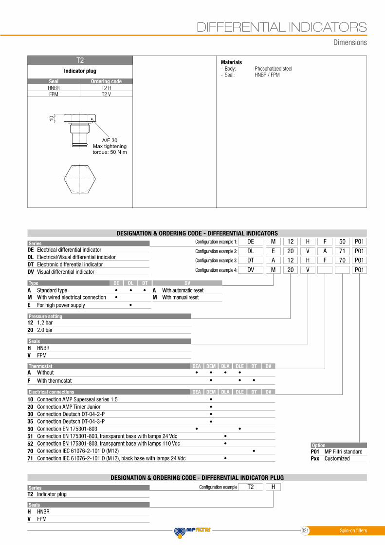
T2 HT2 V
HNBRFPM
Seal Ordering code
Dimensions
DIFFERENTIAL INDICATORS
Series
Series
DE
T2
DL
DVDT
OptionP01Pxx
MP Filtri standardCustomized
Configuration example 1: DE HM 50F12 P01
Configuration example T2 H
Configuration example 2: DL VE 71A20 P01Configuration example 3: DT HA 70F12 P01
Configuration example 4: DV VM 20 P01
TypeA A
EM M
Pressure setting1220
1.2 bar2.0 bar
Standard type With automatic reset
Electrical differential indicator
Indicator plug
For high power supply
Electronic differential indicator
With wired electrical connection With manual reset
Electrical/Visual differential indicator
Visual differential indicator
DESIGNATION & ORDERING CODE - DIFFERENTIAL INDICATORS
DESIGNATION & ORDERING CODE - DIFFERENTIAL INDICATOR PLUG
Seals
Seals
H
H
V
V
HNBR
HNBR
FPM
FPM
••
•
• •
Electrical connections
2010
30
50
52
35
51
7071
DL
DLE
DLE
DEA
DEA
DE DT
DT
DT
DEM
DEM
DV
DV
DV
DLA
DLA
•
• •
•
••••
•
•
•
••
•
• • •
ThermostatAF
WithoutWith thermostat
Indicator plug
T2 Materials- Body: Phosphatized steel- Seal: HNBR / FPM
10A
/F30
Connection Deutsch DT-04-2-PConnection AMP Timer JuniorConnection AMP Superseal series 1.5
Connection Deutsch DT-04-3-PConnection EN 175301-803
Connection EN 175301-803, transparent base with lamps 110 VdcConnection EN 175301-803, transparent base with lamps 24 Vdc
Connection IEC 61076-2-101 D (M12)Connection IEC 61076-2-101 D (M12), black base with lamps 24 Vdc
A/F 30Max tighteningtorque: 50 N∙m
Spin-on filters321

Clogging indicators are devices that check the life time of the filter elements.They measure the pressure drop through the filter element directly connected to the filter housing.These devices trip when the clogging of the filter element causes a pressure drop increasing across the filter element.Filter elements are efficient only if their Dirt Holding Capacity is fully exploited.This is achieved by using filter housings equipped with clogging indicators.The indicator is set to alarm before the element becomes fully clogged.
MP Filtri can supply indicators of the following designs: - Vacuum switches and gauges - Pressure switches and gauges - Differential pressure indicators
These type of devices can be provided with a visual, electrical or both signals.The electronic differential pressure clogging indicator is also available. It provides both analogical 4-20 mA output and digital warning (75% of clogging) and alarm (clogging) outputs.
Clogging Indicators 636
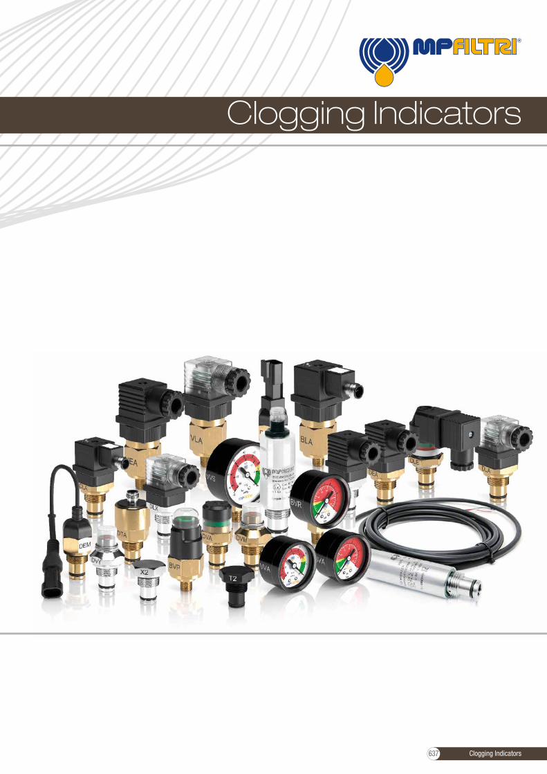
Clogging Indicators
Clogging Indicators637

Clogging indicators
Clogging indicators
Suitable indicator types
BAROMETRIC INDICATORSPressure indicators are used on the Return line to check the effi ciency of the fi lter element.They measure the pressure upstream of the fi lter element.Standard items are produced with R 1/8” EN 10226 connection.
DIFFERENTIAL INDICATORSDifferential indicators are used on the Pressure line to check the effi ciency of the fi lter element.They measure the pressure upstream and downstream of the fi lter element (differential pressure).Standard items are produced with special connection G 1/2” size.Also available in Stainless Steel models.
VACUUM INDICATORSVacuum indicators are used on the Suction line to check the effi ciency of the fi lter element.They measure the pressure downstream of the fi lter element.Standard items are produced with R 1/4” EN 10226 connection.Available products with R 1/8” EN 10226 to be fi tted on MPS series.
Clogging Indicators 638
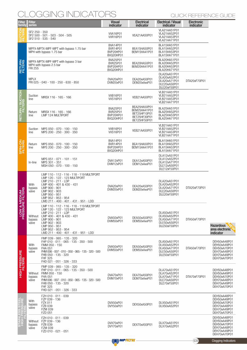
NEWHazardous
area electronicindicator
QUICK REFERENCE GUIDEFilter series
Filter family
Visualindicator
Electricalindicator
Electrical / Visualindicator
Electronicindicator
RE
TU
RN
FIL
TE
RS
RE
TU
RN
/ S
UC
TIO
N
FIL
TE
RS
SP
IN-O
N
FIL
TE
RS
LO
W &
ME
DIU
MP
RE
SS
UR
E F
ILTE
RS
HIG
H P
RE
SS
UR
EFIL
TE
RS
STA
INLE
SS
STE
EL
HIG
H P
RE
SS
UR
EFIL
TE
RS
SU
CTIO
N
FIL
TE
RS
DTA20xF70P01
DTA20xF70P01
DTA50xF70P01
DTA50xF70P01
DTA70xF70P01
VLA21AA51P01VLA21AA52P01VLA21AA53P01VLA21AA71P01
DLA20xA51P01DLA20xA52P01DLA20xA71P01DLE20xA50P01DLE20xF50P01
BLA15HA51P01BLA15HA52P01BLA15HA53P01BLA15HA71P01
BLA20HA51P01BLA20HA52P01BLA20HA53P01BLA20HA71P01
VLB21AA51P01VLB21AA52P01VLB21AA53P01VLB21AA71P01
BLA25HA51P01BLA25HA52P01BLA25HA53P01BLA25HA71P01
VLB21AA51P01VLB21AA52P01VLB21AA53P01VLB21AA71P01
BLA15HA51P01BLA15HA52P01BLA15HA53P01BLA15HA71P01
DLA12xA51P01DLA12xA52P01DLA12xA71P01DLE12xA50P01DLE12xF50P01
DLA20xA51P01DLA20xA52P01DLA20xA71P01DLE20xA50P01DLE20xF50P01
DLA50xA51P01DLA50xA52P01DLA50xA71P01DLE50xA50P01DLE50xF50P01
DLA50xA51P01DLA50xA52P01DLA50xA71P01DLE50xA50P01DLE50xF50P01
DLA70xA51P01DLA70xA52P01DLA70xA71P01DLE70xA50P01DLE70xF50P01
DLX50xA51P01DLX50xA52P01
DLX70xA51P01DLX70xA52P01
VVA16P01VVR16P01
DVA20xP01DVM20xP01
BVA14P01BVR14P01
BVP20HP01BVQ20HP01
BVA25P01BVR25P01
BVP20HP01BVQ20HP01
VVB16P01VVS16P01
BVA25P01BVR25P01
BVP20HP01BVQ20HP01
VVB16P01VVS16P01
BVA14P01BVR14P01
BVP20HP01BVQ20HP01
DVA12xP01DVM12xP01
DVA20xP01DVM20xP01
DVA50xP01DVM50xP01
DVA50xP01DVM50xP01
DVA70xP01DVM70xP01
DVX50xP01DVY50xP01
DVX70xP01DVY70xP01
VEA21AA50P01
DEA20xA50P01DEM20xAxxP01
BEA15HA50P01BEM15HA41P01
BEA20HA50P01BEM20HA41P01
VEB21AA50P01
BEA25HA50P01BEM25HA41P01BET25HF10P01BET25HF30P01BET25HF50P01
VEB21AA50P01
BEA15HA50P01BEM15HA41P01
DEA12xA50P01DEM12xAxxP01
DEA20xA50P01DEM20xAxxP01
DEA50xA50P01DEM50xAxxP01
DEA50xA50P01DEM50xAxxP01
DEA70xA50P01DEM70xAxxP01
DEX50xA50P01
DEX70xA50P01
SF2 250 - 350SF2 500 - 501 - 503 - 504 - 505SF2 510 - 535 - 540
MPLXFRI 025 - 040 - 100 - 250 - 630 - 850
MPFX-MPTX-MPF-MPT with bypass 1.75 barMPH with bypass 1.75 bar
MPFX-MPTX-MPF-MPT with bypass 3 barMPH with bypass 2.5 barFRI 255
MRSX 116 - 165 - 166Suctionline
MRSX 116 - 165 - 166LMP 124 MULTIPORT
Returnline
MPS 050 - 070 - 100 - 150MPS 200 - 250 - 300 - 350
Suctionline
MPS 050 - 070 - 100 - 150MPS 200 - 250 - 300 - 350
Returnline
MPS 051 - 071 - 101 - 151MPS 301 - 351MSH 050 - 070 - 100 - 150
In-line
LMP 110 - 112 - 116 - 118 - 119 MULTIPORTLMP 120 - 122 - 123 MULTIPORTLMP 210 - 211 - LDPLMP 400 - 401 & 430 - 431LMP 900 - 901LMP 902 - 903LMP 950 - 951LMP 952 - 953 - 954LMD 211 - 400 - 401 - 431 - 951 - LDD
With bypass valve
LMP 110 - 112 - 116 - 118 - 119 MULTIPORTLMP 120 - 122 - 123 MULTIPORTLMP 210 - 211 - LDPLMP 400 - 401 & 430 - 431LMP 900 - 901LMP 902 - 903LMP 950 - 951LMP 952 - 953 - 954LMD 211 - 400 - 401 - 431 - 951 - LDD
Without bypass valve
FMP 039 - 065 - 135 - 320FHP 010 - 011 - 065 - 135 - 350 - 500FMM 050 - 150FHA 051FHM 006 - 007 - 010 - 050 - 065 - 135 - 320 - 500FHB 050 - 135 - 320FHF 325FHD 021 - 051 - 326 - 333
With bypass valve
FMP 039 - 065 - 135 - 320FHP 010 - 011 - 065 - 135 - 350 - 500FMM 050 - 150FHA 051FHM 006 - 007 - 010 - 050 - 065 - 135 - 320 - 500FHB 050 - 135 - 320FHF 325FHD 021 - 051 - 326 - 333
Without bypass valve
FZH 010 - 011 - 039FZP 039 - 136FZX 011FZB 039FZM 039FZD 051
With bypass valve
FZH 010 - 011 - 039FZP 039 - 136FZB 039FZM 039FZD 010 - 021 - 051
Without bypass valve
DEH50xA48P01DEH50xA49P01DEH50xA70P01DEH70xA48P01DEH70xA49P01DEH70xA70P01
DEH50xA48P01DEH50xA49P01DEH50xA70P01DEH70xA48P01DEH70xA49P01DEH70xA70P01
DEH50xA48P01DEH50xA49P01DEH50xA70P01DEH70xA48P01DEH70xA49P01DEH70xA70P01
DEH50xA48P01DEH50xA49P01DEH50xA70P01DEH70xA48P01DEH70xA49P01DEH70xA70P01
CLOGGING INDICATORS
Clogging Indicators639

All data, details and words contained in this publication are provided for information purposes only.MP Filtri reserves the right to make modifications to the models and versions of the described products at any time
for both technical and / or commercial reasons.The colors and the pictures of the products are purely indicative.
Any reproduction, partial or total, of this document is strictly forbidden.All rights are strictly reserved.
640


mpfiltri.com
WORLDWIDE
TO PERFORM
NETWORK
PASSION
EN
- R
ev. 1
2-20
19C
MP
EN
001G
HEADQUARTERS
ITALFILTRI LLCMoscow - Russia+7 (495) 220 94 60 [email protected]
MP Filtri Canada Inc.Concord, Ontario - Canada+1 905 303 [email protected]
MP Filtri France SASVilleneuve la GarenneParis - France+33 (0)1 40 86 47 [email protected]
MP Filtri Germany GmbHSt. Ingbert - Germany +49 (0) 6894 95652 [email protected]
MP Filtri India Pvt. Ltd.Bangalore - India+91 80 4147 7444 / +91 80 4146 [email protected]
MP Filtri (Shanghai) Co., Ltd.Shanghai - Minhang District- China+86 21 58919916 [email protected]
MP Filtri U.K. Ltd.Bourton on the WaterGloucestershire - United Kingdom+44 (0) 1451 822 522 [email protected]
MP Filtri U.S.A. Inc.Quakertown, PA - U.S.A.+1 215 529 [email protected]
BRANCH OFFICES
MP Filtri S.p.A.Pessano con BornagoMilano - Italy+39 02 [email protected]