Embed Size (px)
Citation preview

High Country Tek, Inc.
Electro-Hydraulic Solutions for Mobile, Industrial & Marine Applications.
Hydraulic Fan System Controller - HFS-3-12v
Part No. HFS-3-12v RevC November 2009
Hydraulic Fan System
Controller – 12V – 1200mA
Application, Set-up
&
Information Manual.
Hydraulic Fan System Controller – HFS-3-12v
This product has been designed by High Country Tek, Inc ( HCT ) to interface directly with any manufacturers
range of proportional pressure and/or flow control valves, variable pumps, motors and manifold blocks currently
available for this type of system.
Please contact the factory by the e-mail address given below or nearest High Country Tek, Inc. distributor for
further technical information and availability.
• Controller Module with DIN 43650 connector :-………………………………………….….P/No: HFS-3-12v
• Controller info manual:-……………………………………………………..……….……..…………P/No: HFS-3-12v RevC
IMPORTANT NOTE:-
High Country Tek, Inc. reserves the right to upgrade, revise or better any controller as technology improves without
notice being given.
Wherever possible, full downwards compatibility for both hardware and software on replaced controllers will be
maintained but it is the users responsibility to ensure that the latest technical details or literature is being used for
application reference.
If you are unsure of the literature, hardware or software revisions you have, or suspect that it is an older revision,
please send an e-mail request for the latest releases to [email protected]
ALL information contained herein is copyrighted to High Country Tek, Inc - © 2009.
• ON and OFF road application suitability
• OEM, re-power and retro-fit markets
• Mining equipment – above and below ground
• Drill, exploration and blast hole rigs
• Chassis, bus and RV builders
• Static applications – standby generators
• Industrial cooling operations
• Liquid nitrogen/oxygen temperature conditioning
• Hydraulic system oil
• Automatic Transmission fluid
• Engine sump oil
• Air conditioner refrigerant
• Engine water jacket
• Engine charge air
• ‘External Attachment’ system fluids
• Diesel fuel conditioning
Important Notes:
Application Areas:
System Part Numbers:
2
Hydraulic Fan System Controller – HFS-3-12v
ALL information contained herein is copyrighted to High Country Tek, Inc - © 2009.
Product Overview:
3
Self contained controller plug for Mobile, Industrial or Marine Hydraulic fan cooling systems.
Interfaces directly with engine PWM fan speed signal.
Space saving - ‘ON-Valve’ mounting using standard DIN 43650 connector.
EMC compliant product to EN50081-1 and EN50082-2 ( heavy industrial )
1 x proportional MosFet driver output ( PWM ) at upto 1200mA ( @12VDC ).
Sealed and environmentally protected to IP68 or NEMA 6P
Flame proof resin ‘Encapsulated’ version to suit application environment.
No extra DIN housing or ‘Card Holder’ to buy.
Pre-wired with 3 meters ( ≈10 ft ) of colour coded cable for fast reliable connection.
Fully ‘isolated’ design for improved safety and ease of application difficult areas.
Unit status ‘Diagnostic’ LED visible through opaque plug cover.
Low cost compared to other available modules with comparative functions.
Easy to use ‘top entry’ adjustments for all major parameters..
Single turn potentiometer ( 1 turns ) ‘I Min’ adjustment for driven solenoid
Multiturn potentiometer ( 20 turns ) ‘I Max’ adjustment for driven solenoid.
‘Dither’ frequency Variable ( single turn ) from 100Hz to 250Hz ( +/-20%).
Heavy duty approved cable for all application environments.
Protected inputs and user outputs for maximum reliability and product life.
This driver unit has been designed to interface and operate with:-
• Wide supply range 10VDC to 14VDC ( 12V nominal )
• Engine Control Unit ( ECU ) 5% to 95% PWM output with 0.5 to 4.5V ( based on 5V maximum ) and
• PWM frequency input from 20 – 125Hz.
• Fan system control manifold blocks.
• Vane and Gear motors with internal or external pressure control valves.
• Piston pump with remote compensator using proportional pilot pressure valves.
• Systems with 12VDC cartridge valves as fluid controlling elements Positive or Negative logic.
Product Features:
Hydraulic Fan System Controller – HFS-3-12v
4
ALWAYS - Take a few minutes to FULLY read THESE information / data sheets BEFORE starting.
ALWAYS - Keep High Voltage AC cables separate from Low Voltage DC signal and supply cables.
ALWAYS - Make sure the unit supply voltage is the same as the coils on the valve being driven !
ALWAYS - Ensure that you are aware of the available adjustments and consequences on the electronics and hydraulics.
ALWAYS - Make sure you have the correct tools to do the intended job ( i.e. P.C., software ) e.t.c.
ALWAYS – ‘Isolate’ this unit from all other equipment BEFORE any form of welding takes place.
ALWAYS - Check ALL connections to and from this unit to ensure NO short or OPEN circuits.
ALWAYS - Check the units supply voltage is CORRECT, ‘ ELECTRICALLY CLEAN ’ and STABLE.
ALWAYS - Operate the units within specified operating temperature for best & reliable performance.
ALWAYS - Ensure that any unused wires / terminals are terminated safely and not shorted together.
ALWAYS - Isolate the controller if ANY form of battery charging or battery boosting takes place on the vehicle.
ALWAYS - Ensure ALL valve connectors are wired correctly, secure, locked and connected to correct coils.
ALWAYS - Observe the set-up procedures in this manual for best operational results.
ALWAYS - Follow and abide by local and country health and safety standards – protect yourself and others !
NEVER - Arc Weld or Charge Batteries with this driver unit connected as damage can occur.
NEVER - Attempt to use this unit if you are unsure of electrical OR hydraulic connections or expected operation.
NEVER - Attempt to use this unit in Areas where other AC or DC coils HAVE NOT been fully suppressed.
NEVER - Use a power supply that is not rated for the correct required O/P current under full load.
NEVER - Allow wires TO or FROM the unit to short circuit ( to each other or chassis/cabinet e.t.c. ).
NEVER - Attempt to use this unit in areas of intense RF without adequate screening measures.
NEVER - Disconnect or connect wires to or from this unit unless it isolated from the power supply.
NEVER - Use this unit in temperatures that exceed those specified as operation may be effected.
NEVER - Start this unit without ensuring ALL work areas are clear of personnel !
The information in this guide is the intellectual property of High Country Tek, Inc. and should be considered at
all times as strictly company confidential.
It shall not be copied or transmitted by any format to any third parties without our knowledge and express
written permission.
Important Notes:
Hydraulic Fan System Controller – HFS-3-12v
ALL information contained herein is copyrighted to High Country Tek, Inc - © 2009.
Important Notes:
5
High Country Tek, Inc ( HCT ) recognizes that fan drive systems are an important part of the protection
needed for the engine and associated peripheral components to ensure maximum reliability, productivity
and long term operation. The fan drive system controller, HFS-3-12v offered by HCT will save fuel, reduce
emissions ( particle and noise ) and increase application productivity by only operating the fan when
required and matching the fan speed to the heat load that requires dissipation.
For fail-safe operation, HCT strongly recommends that the hydraulic valves used are of the ‘Negative logic’
variety. This means that the valve gives less pressure for an increasing drive current. This choice results in
full pressure and therefore defaults to full fan speed in the event of the electronic controller or the fan
speed requirement signal being dis-connected or disabled.
There are situations where full fan speed with no drive current may not be optimal so the controller in this
manual allows the user the choice of either ‘negative logic’ or positive logic ( Increasing pressure with
increasing current ) valves by a simple link setting, found under the units lid.
Because the controller is designed to connect directly to the engine ECU, all the decisions on ramp rates,
proportionality, slope angle e.t.c. are already calculated to suit the application. This means that adjustment
of the controller is simple with only five potentiometers –
Dither frequency ( which is needed to ensure correct, repeatable and smooth valve operation ).
I Min ( which sets the Max fan speed on Negative logic valves or Min fan speed in positive logic circuits ).
I Max (which sets the Min fan speed on Negative logic valves or Max fan speed in positive logic circuits).
To maintain operational integrity and prevent unauthorized adjustments once set, the assembly of the
driver is such that the enclosure containing the electronics ( electronic printed circuit board and
components are fully isolated from the casing ) must be assembled as described in this manual and
mounted to the valve coil with the correct length screw.
The controller electronics are fully encapsulated in black flame proof resin to allow continuous operation in
adverse conditions while protecting them from vibration and external environmental influences.
This unit has been designed to meet all the current EMC requirements and is a well proven control circuit
with many years of field and time proven operation.
Important Note:-
Please be aware that fan blades can start rotating without warning and may cause
personal injury if precautions are not taken and safe working practices observed.
Hydraulic Fan System Controller – HFS-3-12v
6
1) Board Style: HCT Unique Size and Mounting.
2) Connector Type: DIN 43650
3) Cable Type: Pre-connected 3M (~10ft) colour coded cable fitted.
4) Input Supply Voltage(s): 12V D.C. ( +10 - +14VDC absolute maximum )
5) Input Supply Current ( Max ): Maximum Valve Current Setting + 50mA Quiescent (Max)
6) Command Input Type: PWM ( From ECU ).
7) Command Input Value: 5V ( 10% to 90% PWM typical range ).
8) Command Input Frequency: 20 to 125Hz
9) Available adjustments: I Max, I Min,
Dither Frequency adjust.
11) Dither Frequency : Variable from 100Hz to 250Hz ( +/- 20% )
12) Environmental: Totally ‘ENCAPSULATED’ Printed Circuit Board.
13) IP Rating: IP68 ( Min ) ( When assembled correctly )
14) NEMA Rating: NEMA 6P
15) Humidity: 95% Non Condensing.
16) Storage temp.: 120 Deg C ( Max )
17) Working temp.: -20 Deg C ( max ) to +70 Deg C ( Max ) Inc Ambient.
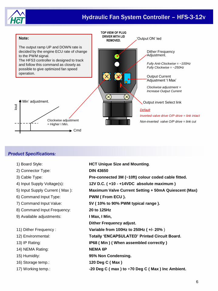
TOP VIEW OF PLUG
DRIVER WITH LID
REMOVED.
Product Specifications:
Note:
The output ramp UP and DOWN rate is
decided by the engine ECU rate of change
to the PWM signal.
The HFS3 controller is designed to track
and follow this command as closely as
possible to give optimized fan speed
operation.
Fully Anti-Clockwise = ~100Hz
Fully Clockwise = ~250Hz
Cmd
Clockwise adjustment
= Higher I Min.
‘I Min’ adjustment.
Iou
t
Output CurrentAdjustment ‘I Max’
Clockwise adjustment =
Increase Output Current
‘Output ON’ led
Dither Frequency Adjustment.
Output invert Select link
Default
Inverted valve drive O/P drive = link intact
Non-inverted valve O/P drive = link cut
Hydraulic Fan System Controller – HFS-3-12v
7
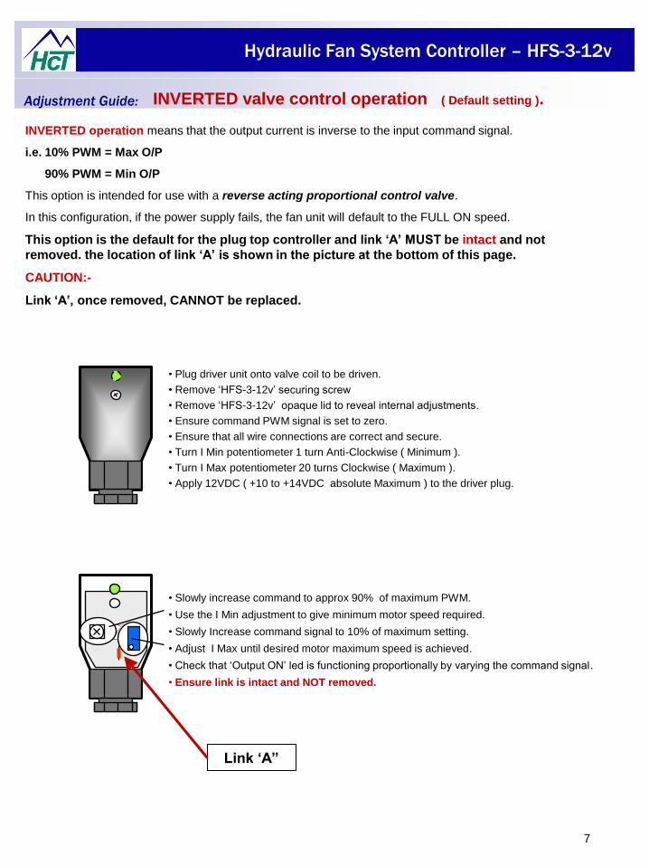
• Plug driver unit onto valve coil to be driven.
• Remove ‘HFS-3-12v’ securing screw
• Remove ‘HFS-3-12v’ opaque lid to reveal internal adjustments.
• Ensure command PWM signal is set to zero.
• Ensure that all wire connections are correct and secure.
• Turn I Min potentiometer 1 turn Anti-Clockwise ( Minimum ).
• Turn I Max potentiometer 20 turns Clockwise ( Maximum ).
• Apply 12VDC ( +10 to +14VDC absolute Maximum ) to the driver plug.
INVERTED operation means that the output current is inverse to the input command signal.
i.e. 10% PWM = Max O/P
90% PWM = Min O/P
This option is intended for use with a reverse acting proportional control valve.
In this configuration, if the power supply fails, the fan unit will default to the FULL ON speed.
This option is the default for the plug top controller and link ‘A’ MUST be intact and not
removed. the location of link ‘A’ is shown in the picture at the bottom of this page.
CAUTION:-
Link ‘A’, once removed, CANNOT be replaced.
• Slowly increase command to approx 90% of maximum PWM.
• Use the I Min adjustment to give minimum motor speed required.
• Slowly Increase command signal to 10% of maximum setting.
• Adjust I Max until desired motor maximum speed is achieved.
• Check that ‘Output ON’ led is functioning proportionally by varying the command signal.
• Ensure link is intact and NOT removed.
Adjustment Guide: INVERTED valve control operation ( Default setting ).
Link ‘A”
Hydraulic Fan System Controller – HFS-3-12v
8
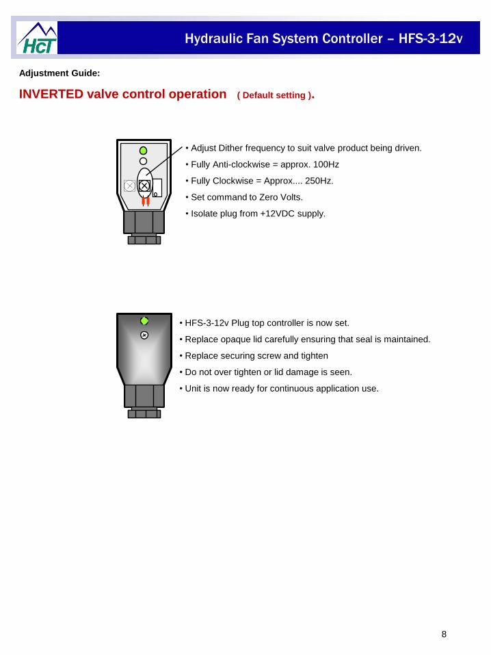
Adjustment Guide:
INVERTED valve control operation ( Default setting ).
• HFS-3-12v Plug top controller is now set.
• Replace opaque lid carefully ensuring that seal is maintained.
• Replace securing screw and tighten
• Do not over tighten or lid damage is seen.
• Unit is now ready for continuous application use.
• Adjust Dither frequency to suit valve product being driven.
• Fully Anti-clockwise = approx. 100Hz
• Fully Clockwise = Approx.... 250Hz.
• Set command to Zero Volts.
• Isolate plug from +12VDC supply.
Hydraulic Fan System Controller – HFS-3-12v
9
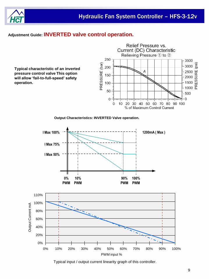
Adjustment Guide: INVERTED valve control operation.
Output Characteristics: INVERTED Valve operation.
I Max 100%
I Max 75%
I Max 50%
90%
PWM
10%
PWM
1200mA ( Max )
0%
PWM
100%
PWM
Typical input / output current linearity graph of this controller.
0%
20%
40%
60%
80%
100%
110%
Ou
tpu
t C
urr
en
t m
A
0% 20% 30% 40% 50% 60% 70% 80% 100%
PWM input %
10% 90%
Typical characteristic of an inverted
pressure control valve This option
will allow ‘fail-to-full-speed’ safety
operation.
Hydraulic Fan System Controller – HFS-3-12v
10
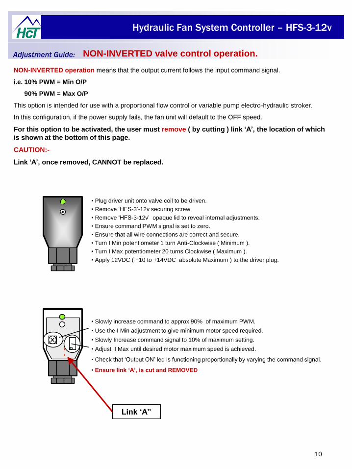
• Plug driver unit onto valve coil to be driven.
• Remove ‘HFS-3’-12v securing screw
• Remove ‘HFS-3-12v’ opaque lid to reveal internal adjustments.
• Ensure command PWM signal is set to zero.
• Ensure that all wire connections are correct and secure.
• Turn I Min potentiometer 1 turn Anti-Clockwise ( Minimum ).
• Turn I Max potentiometer 20 turns Clockwise ( Maximum ).
• Apply 12VDC ( +10 to +14VDC absolute Maximum ) to the driver plug.
NON-INVERTED operation means that the output current follows the input command signal.
i.e. 10% PWM = Min O/P
90% PWM = Max O/P
This option is intended for use with a proportional flow control or variable pump electro-hydraulic stroker.
In this configuration, if the power supply fails, the fan unit will default to the OFF speed.
For this option to be activated, the user must remove ( by cutting ) link ‘A’, the location of which
is shown at the bottom of this page.
CAUTION:-
Link ‘A’, once removed, CANNOT be replaced.
• Slowly increase command to approx 90% of maximum PWM.
• Use the I Min adjustment to give minimum motor speed required.
• Slowly Increase command signal to 10% of maximum setting.
• Adjust I Max until desired motor maximum speed is achieved.
• Check that ‘Output ON’ led is functioning proportionally by varying the command signal.
• Ensure link ‘A’, is cut and REMOVED
Adjustment Guide: NON-INVERTED valve control operation.
Link ‘A”
Hydraulic Fan System Controller – HFS-3-12v
11
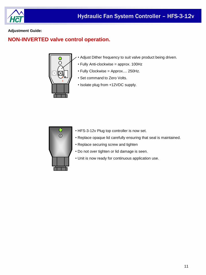
Adjustment Guide:
NON-INVERTED valve control operation.
• HFS-3-12v Plug top controller is now set.
• Replace opaque lid carefully ensuring that seal is maintained.
• Replace securing screw and tighten
• Do not over tighten or lid damage is seen.
• Unit is now ready for continuous application use.
• Adjust Dither frequency to suit valve product being driven.
• Fully Anti-clockwise = approx. 100Hz
• Fully Clockwise = Approx.... 250Hz.
• Set command to Zero Volts.
• Isolate plug from +12VDC supply.
Hydraulic Fan System Controller – HFS-3-12v
12
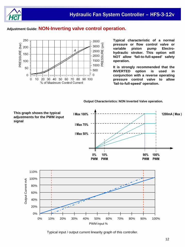
Adjustment Guide: NON-Inverting valve control operation.
Output Characteristics: NON Inverted Valve operation.
I Max 100%
I Max 75%
I Max 50%
90%
PWM
10%
PWM
1200mA ( Max )
0%
PWM
100%
PWM
This graph shows the typical
adjustments for the PWM input
signal
Typical input / output current linearity graph of this controller.
0%
20%
40%
60%
80%
100%
110%
Ou
tpu
t C
urr
en
t m
A
0% 20% 30% 40% 50% 60% 70% 80% 100%
PWM input %
10% 90%
Typical characteristic of a normal
pressure or flow control valve or
variable piston pump Electro-
hydraulic stroker. This option will
NOT allow ‘fail-to-full-speed’ safety
operation.
It is strongly recommended that the
INVERTED option is used in
conjunction with a reverse operating
pressure control valve to allow
‘fail-to-full-speed’ operation.
Hydraulic Fan System Controller – HFS-3-12v
13
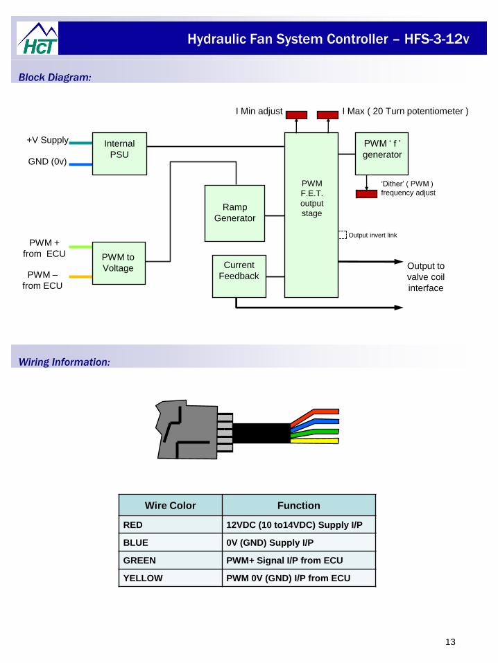
Wire Color Function
RED 12VDC (10 to14VDC) Supply I/P
BLUE 0V (GND) Supply I/P
GREEN PWM+ Signal I/P from ECU
YELLOW PWM 0V (GND) I/P from ECU
Block Diagram:
Wiring Information:
PWM
F.E.T.
output
stage
I Max ( 20 Turn potentiometer )
‘Dither’ ( PWM )
frequency adjust
I Min adjust
+V Supply
GND (0v)
PWM +
from ECU
Internal
PSU
Current
Feedback
PWM ‘ f ’
generator
Output to
valve coil
interface
PWM –
from ECU
PWM to
Voltage
Ramp
Generator
Output invert link
Hydraulic Fan System Controller – HFS-3-12v
14
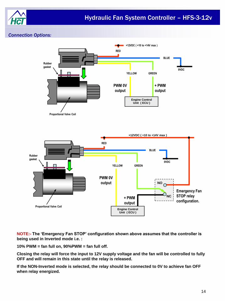
NOTE:- The ‘Emergency Fan STOP’ configuration shown above assumes that the controller is
being used in Inverted mode i.e. :
10% PWM = fan full on, 90%PWM = fan full off.
Closing the relay will force the input to 12V supply voltage and the fan will be controlled to fully
OFF and will remain in this state until the relay is released.
If the NON-Inverted mode is selected, the relay should be connected to 0V to achieve fan OFF
when relay energized.
0VDC
BLUE
GREENYELLOW
RED
Rubber
gasket
+12VDC ( +10 to +14V max )
Engine Control Unit ( ECU )
+ PWM
output
PWM 0V
output
Proportional Valve Coil
0VDC
BLUE
YELLOW
RED
Rubber
gasket
+12VDC ( +10 to +14V max )
+ PWM
output
PWM 0V
output
Proportional Valve Coil
GREEN
Engine Control Unit ( ECU )
Emergency Fan
STOP relay
configuration.
NC
NO
Connection Options:
Hydraulic Fan System Controller – HFS-3-12v
15
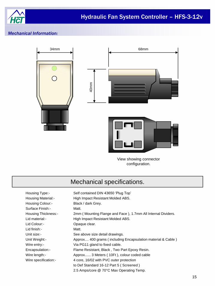
Mechanical Information:
Housing Type:- Self contained DIN 43650 ‘Plug Top’
Housing Material:- High Impact Resistant Molded ABS.
Housing Colour:- Black / dark Grey.
Surface Finish:- Matt.
Housing Thickness:- 2mm ( Mounting Flange and Face ), 1.7mm All Internal Dividers.
Lid material:- High Impact Resistant Molded ABS.
Lid Colour:- Opaque clear.
Lid finish:- Matt.
Unit size:- See above size detail drawings.
Unit Weight:- Approx.... 400 grams ( including Encapsulation material & Cable )
Wire entry:- Via PG11 gland to fixed cable.
Encapsulation:- Flame Resistant, Black , Two Part Epoxy Resin.
Wire length:- Approx...... 3 Meters ( 10Ft ), colour coded cable
Wire specification:- 4 core, 16/02 with PVC outer protection
to Def Standard 16-12 Part 5 ( Screened )
2.5 Amps/core @ 70°C Max Operating Temp.
Mechanical specifications.
View showing connector
configuration.
68mm
40
mm
34mm
Hydraulic Fan System Controller – HFS-3-12v
16
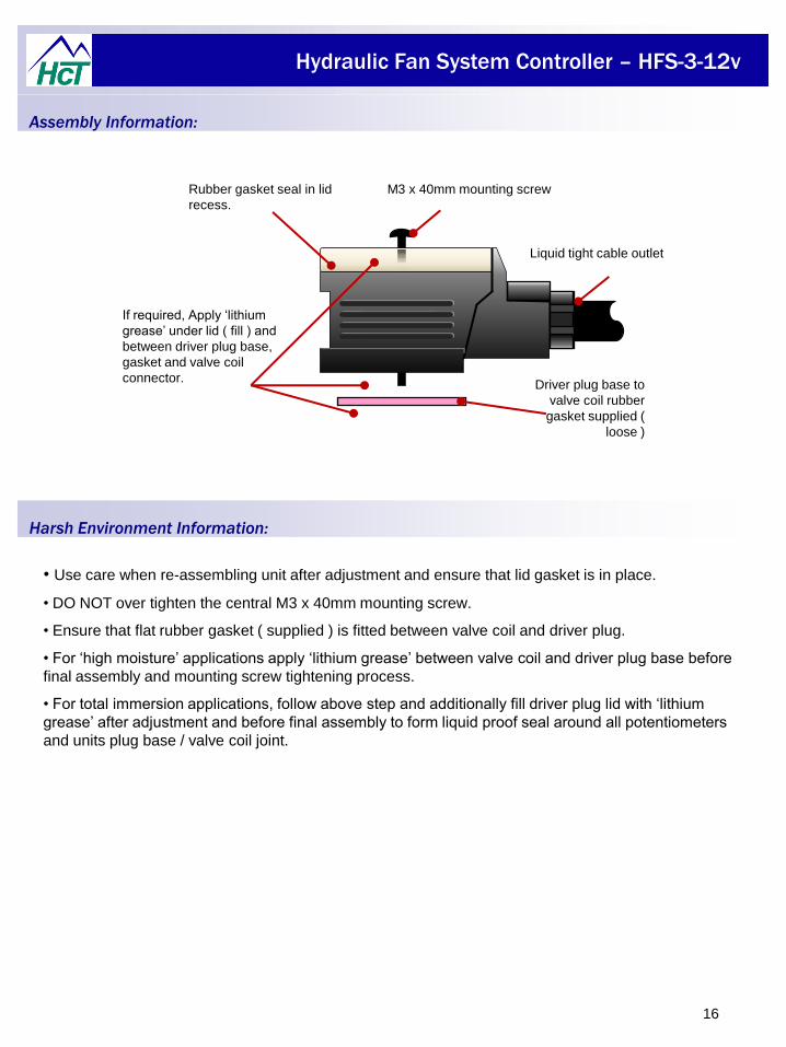
• Use care when re-assembling unit after adjustment and ensure that lid gasket is in place.
• DO NOT over tighten the central M3 x 40mm mounting screw.
• Ensure that flat rubber gasket ( supplied ) is fitted between valve coil and driver plug.
• For ‘high moisture’ applications apply ‘lithium grease’ between valve coil and driver plug base before
final assembly and mounting screw tightening process.
• For total immersion applications, follow above step and additionally fill driver plug lid with ‘lithium
grease’ after adjustment and before final assembly to form liquid proof seal around all potentiometers
and units plug base / valve coil joint.
Assembly Information:
Harsh Environment Information:
Liquid tight cable outlet
Rubber gasket seal in lid
recess.
Driver plug base to
valve coil rubber
gasket supplied (
loose )
M3 x 40mm mounting screw
If required, Apply ‘lithium
grease’ under lid ( fill ) and
between driver plug base,
gasket and valve coil
connector.
Hydraulic Fan System Controller – HFS-3-12v
17
Page left intentionally blank

Hydraulic Fan System Controller – HFS-3-12v
18
Page left intentionally blank

Hydraulic Fan System Controller – HFS-3-12v
19
Page left intentionally blank

Hydraulic Fan System Controller – HFS-3-12v
HFS-3-12v-C Copyright © High Country Tek, Inc. - 2009
Need More Information ?
High Country Tek, Inc.
208 Gold Flat Court
Nevada City, CA, 95959
Tel: (1) 530 265 3236
Fax:(1) 530 265 3275
We currently supply to virtually all areas of the fluid power industry, increasing product integration
and growing our customers business, by allowing them to approach new, profitable electro-hydraulic
markets successfully.
Please contact us to discuss your next project, product training or system application; we would be
pleased to work with you and your team.
High Country Tek, Inc has been working with
the fluid power industry for many years, solving
the tough problems and producing unique and
mechanically robust products that continue to
work reliably in the most extreme and hostile
environments that we see hydraulics being
applied in today.
Our controllers are ALL designed,
manufactured and tested in the U.S.A. and can
be sent anywhere in the world.
For customer service, orders and application
support, contact us through E-mail at:
20
High Country Tek, Inc. reserve the right to improve this product at any time and without notice. This manual
may contain mistakes and printing errors. The information in this publication is regularly checked and
corrections made in the next issue. Please check our website or contact our customer support for latest
version. HCT accepts NO liability for technical mistakes or printing errors, or their consequences.
www.highcountrytek.com


![Untitled-2 [suntracbatteries.com]suntracbatteries.com/suntrac.pdf · capacity 12v 20ah 12v 40ah 12v 60ah 12v b40ah 12v b60ah 12v b80ah 12v biooah 12v 80ah 12v iooah 12v 130ah 12v](https://img.pdfslide.us/doc/110x75/603efb7aa12c32391f5484d1/untitled-2-capacity-12v-20ah-12v-40ah-12v-60ah-12v-b40ah-12v-b60ah-12v-b80ah.jpg)