Embed Size (px)
Citation preview
ZAXIS-5A series
HYDRAULIC EXCAVATORModel Code : ZX55U-5A
Engine Rated Power : 28.2 kW (37.8 HP)Operating Weight : Canopy 4 850 - 5 250 kg Cab 4 980 - 5 380 kgBackhoe Bucket : ISO Heaped : 0.14 m3
� �
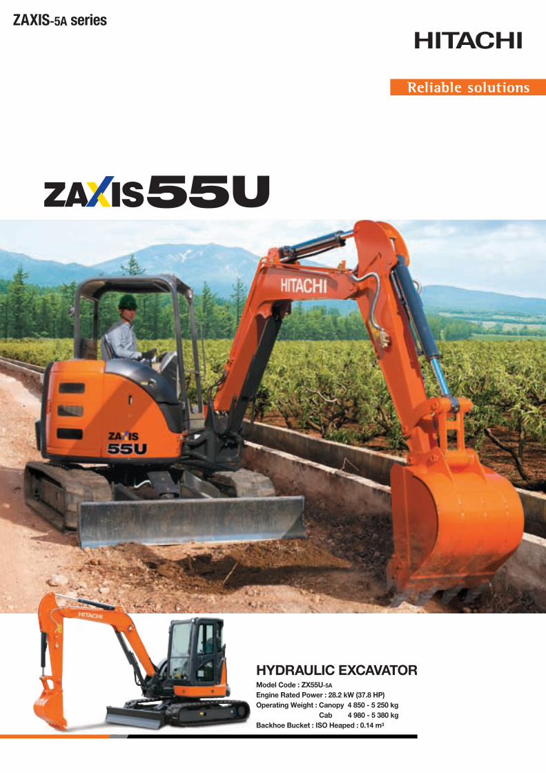
Shown equipped with 1.38 m arm, extra piping, additional counterweight, rear view mirror, and armrests.
Shown equipped with 1.69 m arm, extra piping, additional counterweight, rear view mirror, pre-cleaner, and stack muffler.
Trustworthy and User-FriendlyNew Compact Excavators The new series of Hitachi compact excavators has evolved even more. We listen to
customers’ needs, provide solutions, and adopt fresh ideas into our new products.
The outcome is new excavators that are compact, productive and nimble.
The round body is smart and its wide-opening covers provide direct access to service
points for quick maintenance.
The operator station is full of easy-to-use controls, an informative multi-monitor, and
comfortable operator seat. A low fuel consumption design ensures better fuel efficiency.
Notes: Standard and optional equipment may vary by country, so please consult your Hitachi dealer for details.
∙ A line of Hitachi quality products ∙ Strong front attachment∙ Rugged box-section blade ∙ Sturdy upperstructure
DURABILITY
∙ Open-wide covers for easy maintenance ∙ Easy-to-clean cab floor ∙ Sloped track frame tops for easy mud removal
SIMPLIFIED MAINTENANCE
∙ Pleasant operator environment ∙ Sturdy operator stations by rigorous safety standards ∙ Easy-to-read multi-monitor
OPERATOR COMFORT
∙ Swift actions in narrow work place ∙ Excellent controllability ∙ Reduced fuel consumption
HIGH PERFORMANCE
� �
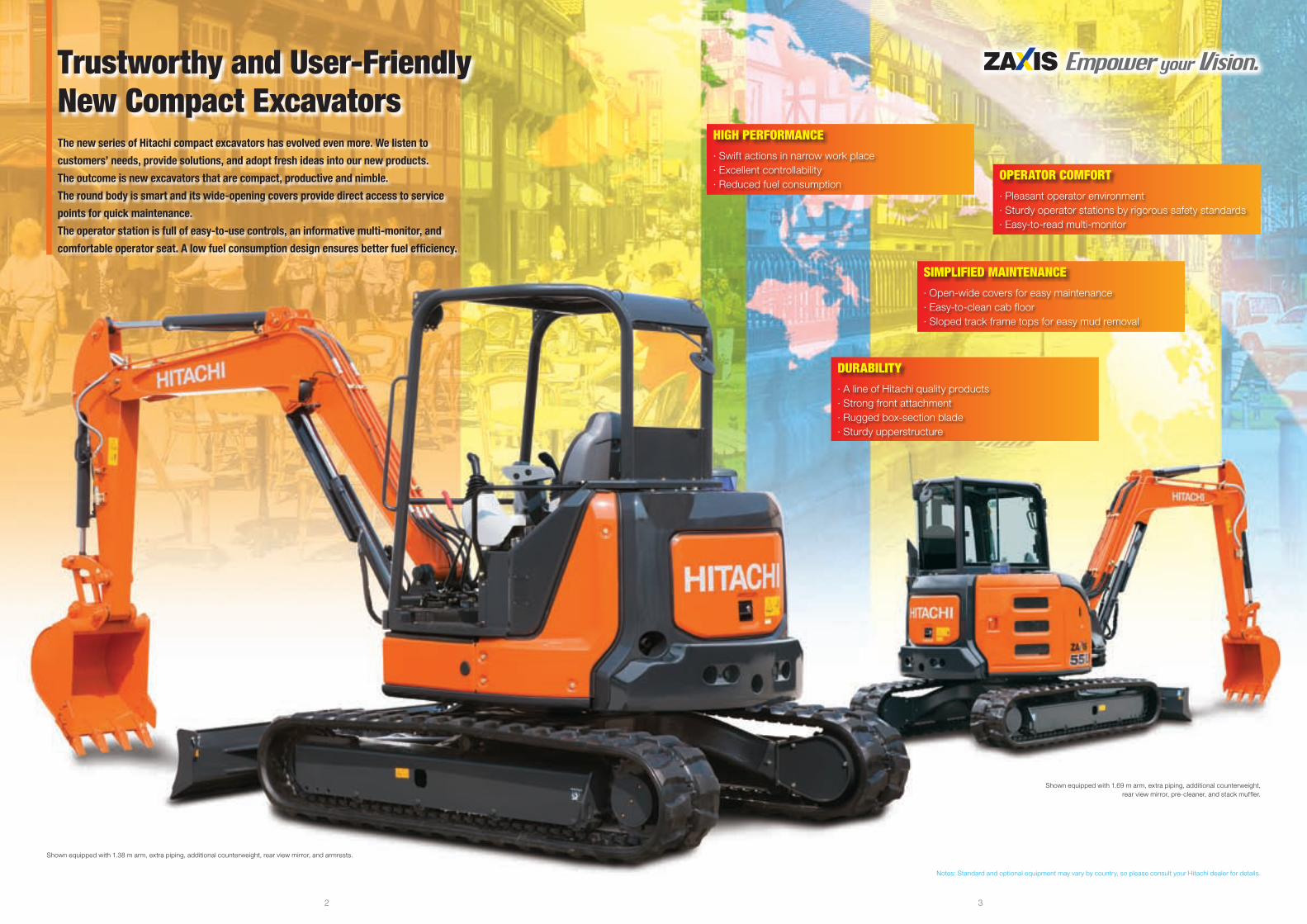
2 000 mm
HIGH PERFORMANCE
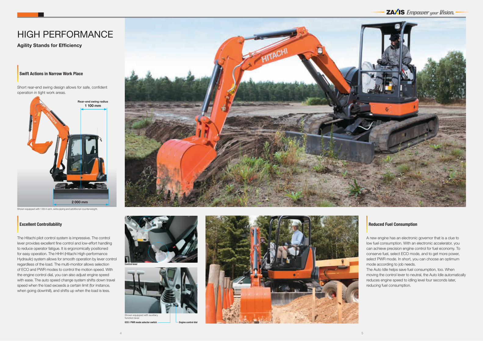
The Hitachi pilot control system is impressive. The control lever provides excellent fine control and low-effort handling to reduce operator fatigue. It is ergonomically positioned for easy operation. The HHH (Hitachi High-performance Hydraulic) system allows for smooth operation by lever control regardless of the load. The multi-monitor allows selection of ECO and PWR modes to control the motion speed. With the engine control dial, you can also adjust engine speed with ease. The auto speed change system shifts down travel speed when the load exceeds a certain limit (for instance, when going downhill), and shifts up when the load is less.
Excellent Controllability
Agility Stands for Efficiency
A new engine has an electronic governor that is a clue to low fuel consumption. With an electronic accelerator, you can achieve precision engine control for fuel economy. To conserve fuel, select ECO mode, and to get more power, select PWR mode. In short, you can choose an optimum mode according to job needs. The Auto Idle helps save fuel consumption, too. When moving the control lever to neutral, the Auto Idle automatically reduces engine speed to idling level four seconds later, reducing fuel consumption.
Reduced Fuel Consumption
Control lever
Shown equipped with 1.69 m arm, extra piping and additional counterweight.
Rear-end swing radius 1 100 mm
Short rear-end swing design allows for safe, confident operation in tight work areas.
Swift Actions in Narrow Work Place
Engine control dialECO / PWR mode selector switch
Shown equipped with auxiliary function lever.
� �
Easy-to-Read Multi-Monitor
The multi-monitor is bright, informative and easy-to-read, displaying machine conditions, settings and warnings. A clock is newly added.
OPERATOR COMFORT
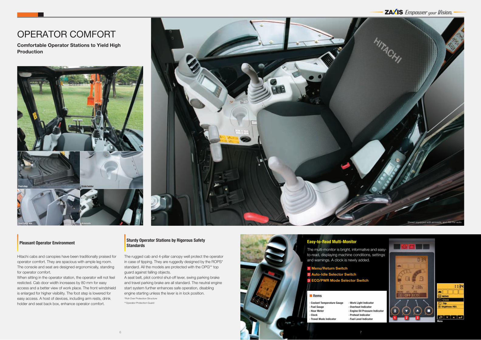
Hitachi cabs and canopies have been traditionally praised for operator comfort. They are spacious with ample leg room. The console and seat are designed ergonomically, standing for operator comfort.When sitting in the operator station, the operator will not feel resticted. Cab door width increases by 80 mm for easy access and a better view of work place. The front windshield is enlarged for higher visibility. The foot step is lowered for easy access. A host of devices, including arm rests, drink holder and seat back box, enhance operator comfort.
Pleasant Operator Environment
The rugged cab and 4-pillar canopy well protect the operator in case of tipping. They are ruggedly designed by the ROPS* standard. All the models are protected with the OPG** top guard against falling objects. A seat belt, pilot control shut-off lever, swing parking brake and travel parking brake are all standard. The neutral engine start system further enhances safe operation, disabling engine starting unless the lever is in lock position. *Roll-Over Protection Structure
**Operator Protection Guard
Sturdy Operator Stations by Rigorous Safety Standards
1 2 3
Comfortable Operator Stations to Yield High Production
Menu
1 Menu/Return Switch
2 Auto-Idle Selector Switch
3 ECO/PWR Mode Selector Switch
Foot step Drink holder
Items
∙ Coolant Temperature Gauge∙ Fuel Gauge∙ Hour Meter∙ Clock∙ Travel Mode Indicator
∙ Work Light Indicator∙ Overheat Indicator∙ Engine Oil Pressure Indicator∙ Preheat Indicator∙ Fuel Level Indicator
Seat back box Armrests Shown equipped with armrests, and AM/FM radio.
� �
Cross-section
SIMPLIFIED MAINTENANCE
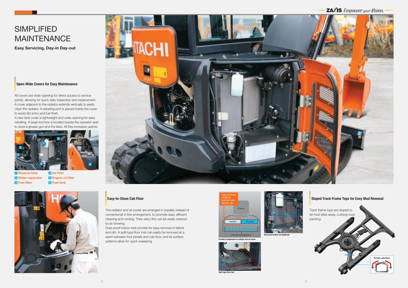
All covers are wide-opening for direct access to service points, allowing for quick daily inspection and replacement. A cover adjacent to the radiator extends vertically to easily clean the radiator. A refueling port is placed inside the cover to avoid dirt entry and fuel theft. A new tank cover is lightweight and wide-opening for easy refueling. A large tool box is located beside the operator seat to store a grease gun and the likes. All this increases uptime.
Open-Wide Covers for Easy Maintenance
The radiator and oil cooler are arranged in parallel, instead of conventional in-line arrangement, to promote easy, efficient cleaning and cooling. Their wavy fins can be easily cleaned by air blowing. Dust-proof indoor nets provide for easy removal of debris and dirt. A split-type floor mat can easily be removed at a seam between foot pedals and cab floor, and its surface patterns allow for quick sweeping.
Easy-to-Clean Cab Floor
Easy Servicing, Day-in Day-out
1 Reserve tank
2 Water separator
3 Fuel filter
4 Air filter
5 Engine oil filter
6 Fuel tank
Split-type floor mat
Parallel arrangement of radiator and oil cooler
Engine
Radiator Oil Cooler
Parallel arrangement
Easy removal of debris and dirt with blower, etc.
Track frame tops are sloped to let mud slide away, curbing mud packing.
Sloped Track Frame Tops for Easy Mud Removal
2
1
4
6
5
3
Dust-proof indoor net (optional)
10 11
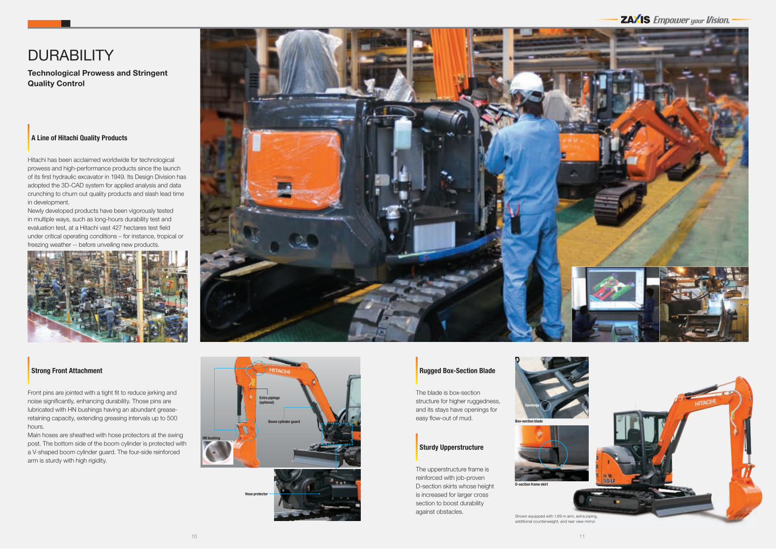
Front pins are jointed with a tight fit to reduce jerking and noise significantly, enhancing durability. Those pins are lubricated with HN bushings having an abundant grease-retaining capacity, extending greasing intervals up to 500 hours. Main hoses are sheathed with hose protectors at the swing post. The bottom side of the boom cylinder is protected with a V-shaped boom cylinder guard. The four-side reinforced arm is sturdy with high rigidity.
Strong Front Attachment
DURABILITY
The blade is box-section structure for higher ruggedness, and its stays have openings for easy flow-out of mud.
Rugged Box-Section Blade
The upperstructure frame is reinforced with job-proven D-section skirts whose height is increased for larger cross section to boost durability against obstacles.
Sturdy Upperstructure
Hitachi has been acclaimed worldwide for technological prowess and high-performance products since the launch of its first hydraulic excavator in 1949. Its Design Division has adopted the 3D-CAD system for applied analysis and data crunching to churn out quality products and slash lead time in development. Newly developed products have been vigorously tested in multiple ways, such as long-hours durability test and evaluation test, at a Hitachi vast 427 hectares test field under critical operating conditions – for instance, tropical or freezing weather -- before unveiling new products.
A Line of Hitachi Quality Products
Technological Prowess and Stringent Quality Control
HN bushing
Hose protector
Boom cylinder guard
Extra pipings(optional)
Box-section blade
Openings
D-section frame skirt
Shown equipped with 1.69 m arm, extra piping, additional counterweight, and rear view mirror.
1� 1�
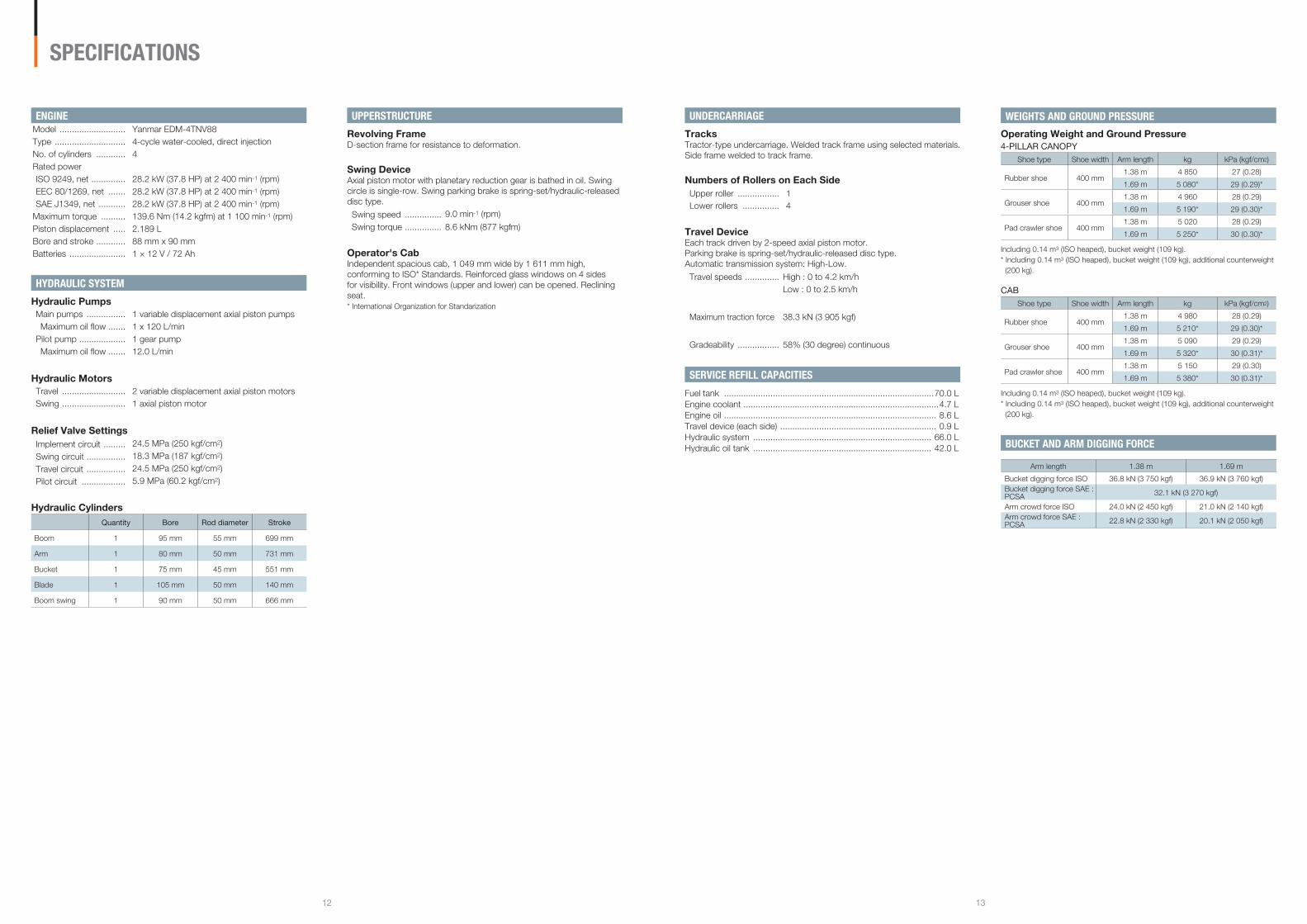
ENGINEModel ........................... Yanmar EDM-4TNV88Type ............................. 4-cycle water-cooled, direct injectionNo. of cylinders ............ 4Rated power ISO 9249, net .............. 28.2 kW (37.8 HP) at 2 400 min-1 (rpm)EEC 80/1269, net ....... 28.2 kW (37.8 HP) at 2 400 min-1 (rpm)SAE J1349, net ........... 28.2 kW (37.8 HP) at 2 400 min-1 (rpm)
Maximum torque .......... 139.6 Nm (14.2 kgfm) at 1 100 min-1 (rpm)Piston displacement ..... 2.189 LBore and stroke ............ 88 mm x 90 mmBatteries ....................... 1 × 12 V / 72 Ah
HYDRAULIC SYSTEM
Hydraulic PumpsMain pumps ................ 1 variable displacement axial piston pumps Maximum oil flow ....... 1 x 120 L/min
Pilot pump ................... 1 gear pumpMaximum oil flow ....... 12.0 L/min
Hydraulic MotorsTravel .......................... 2 variable displacement axial piston motorsSwing .......................... 1 axial piston motor
Relief Valve SettingsImplement circuit ......... 24.5 MPa (250 kgf/cm2)
Swing circuit ................ 18.3 MPa (187 kgf/cm2)
Travel circuit ................ 24.5 MPa (250 kgf/cm2)
Pilot circuit .................. 5.9 MPa (60.2 kgf/cm2)
Hydraulic CylindersQuantity Bore Rod diameter Stroke
Boom 1 95 mm 55 mm 699 mm
Arm 1 80 mm 50 mm 731 mm
Bucket 1 75 mm 45 mm 551 mm
Blade 1 105 mm 50 mm 140 mm
Boom swing 1 90 mm 50 mm 666 mm
SPECIFICATIONS
UNDERCARRIAGE
TracksTractor-type undercarriage. Welded track frame using selected materials. Side frame welded to track frame.
Numbers of Rollers on Each SideUpper roller ................. 1Lower rollers ............... 4
Travel DeviceEach track driven by 2-speed axial piston motor.Parking brake is spring-set/hydraulic-released disc type. Automatic transmission system: High-Low.
Travel speeds .............. High : 0 to 4.2 km/hLow : 0 to 2.5 km/h
Maximum traction force 38.3 kN (3 905 kgf)
Gradeability ................. 58% (30 degree) continuous
SERVICE REFILL CAPACITIES
Fuel tank ......................................................................................70.0 LEngine coolant ................................................................................4.7 LEngine oil ....................................................................................... 8.6 LTravel device (each side) ................................................................ 0.9 LHydraulic system ......................................................................... 66.0 LHydraulic oil tank ......................................................................... 42.0 L
WEIGHTS AND GROUND PRESSURE
Operating Weight and Ground Pressure�-PILLAR CANOPY
Shoe type Shoe width Arm length kg kPa (kgf/cm2)
Rubber shoe 400 mm1.38 m 4 850 27 (0.28)
1.69 m 5 080* 29 (0.29)*
Grouser shoe 400 mm1.38 m 4 960 28 (0.29)
1.69 m 5 190* 29 (0.30)*
Pad crawler shoe 400 mm1.38 m 5 020 28 (0.29)
1.69 m 5 250* 30 (0.30)*
Including 0.14 m3 (ISO heaped), bucket weight (109 kg).* Including 0.14 m3 (ISO heaped), bucket weight (109 kg), additional counterweight
(200 kg).
CABShoe type Shoe width Arm length kg kPa (kgf/cm2)
Rubber shoe 400 mm1.38 m 4 980 28 (0.29)
1.69 m 5 210* 29 (0.30)*
Grouser shoe 400 mm1.38 m 5 090 29 (0.29)
1.69 m 5 320* 30 (0.31)*
Pad crawler shoe 400 mm1.38 m 5 150 29 (0.30)
1.69 m 5 380* 30 (0.31)*
Including 0.14 m3 (ISO heaped), bucket weight (109 kg).* Including 0.14 m3 (ISO heaped), bucket weight (109 kg), additional counterweight
(200 kg).
BUCKET AND ARM DIGGING FORCE
Arm length 1.38 m 1.69 m
Bucket digging force ISO 36.8 kN (3 750 kgf) 36.9 kN (3 760 kgf)Bucket digging force SAE : PCSA 32.1 kN (3 270 kgf)
Arm crowd force ISO 24.0 kN (2 450 kgf) 21.0 kN (2 140 kgf)Arm crowd force SAE : PCSA 22.8 kN (2 330 kgf) 20.1 kN (2 050 kgf)
UPPERSTRUCTURE
Revolving FrameD-section frame for resistance to deformation.
Swing DeviceAxial piston motor with planetary reduction gear is bathed in oil. Swing circle is single-row. Swing parking brake is spring-set/hydraulic-released disc type.
Swing speed ............... 9.0 min-1 (rpm)
Swing torque ............... 8.6 kNm (877 kgfm)
Operator's CabIndependent spacious cab, 1 049 mm wide by 1 611 mm high, conforming to ISO* Standards. Reinforced glass windows on 4 sides for visibility. Front windows (upper and lower) can be opened. Reclining seat. * International Organization for Standarization
1� 1�
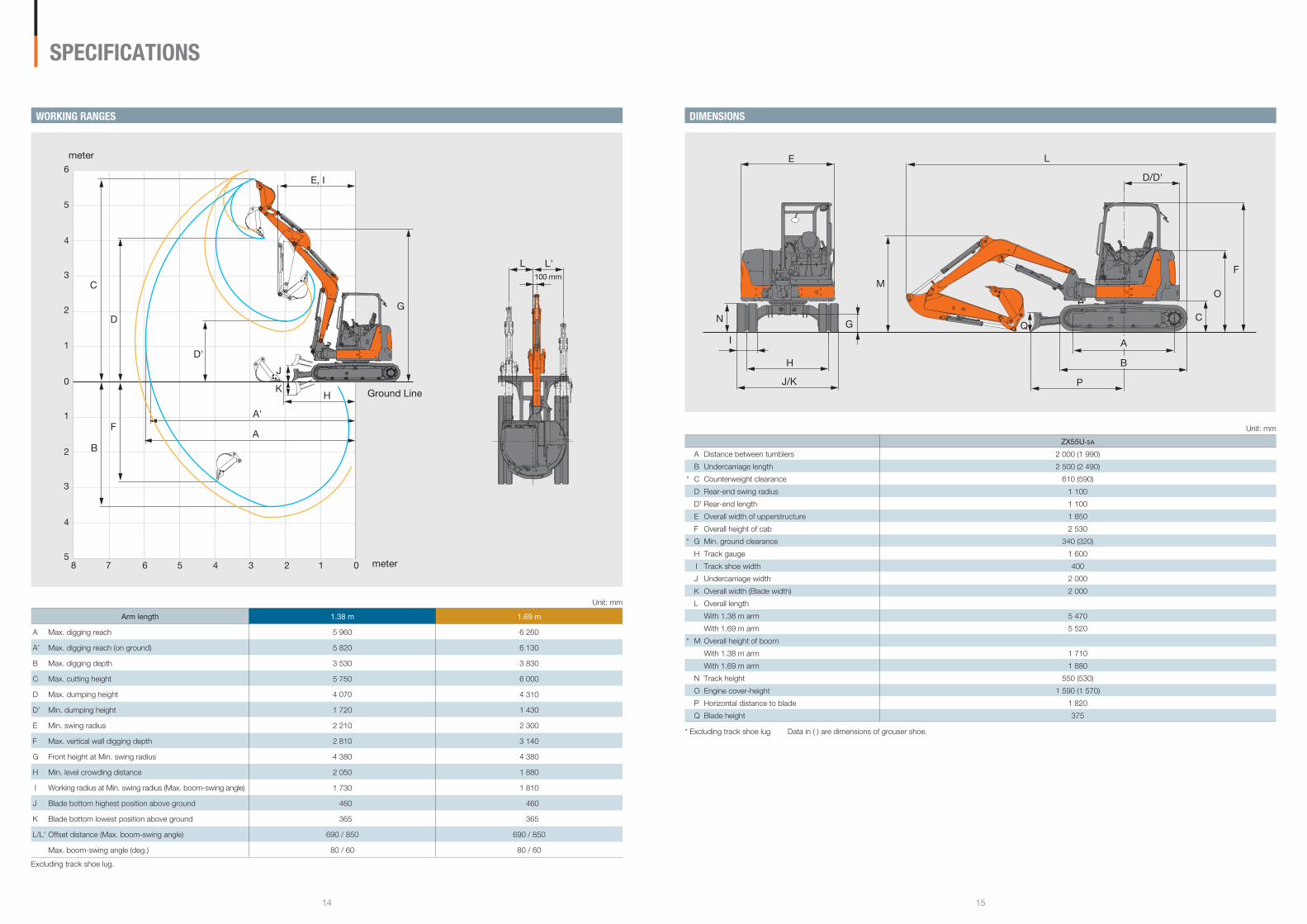
Unit: mm
ZX��U-�A
A Distance between tumblers 2 000 (1 990)
B Undercarriage length 2 500 (2 490)
* C Counterweight clearance 610 (590)
D Rear-end swing radius 1 100
D’ Rear-end length 1 100
E Overall width of upperstructure 1 850
F Overall height of cab 2 530
* G Min. ground clearance 340 (320)
H Track gauge 1 600
I Track shoe width 400
J Undercarriage width 2 000
K Overall width (Blade width) 2 000
L Overall length
With 1.38 m arm 5 470
With 1.69 m arm 5 520
* M Overall height of boom
With 1.38 m arm 1 710
With 1.69 m arm 1 880
N Track height 550 (530)
O Engine cover-height 1 590 (1 570)
P Horizontal distance to blade 1 820
Q Blade height 375
* Excluding track shoe lug Data in ( ) are dimensions of grouser shoe.
C
D/D'
Q
M
G
H
E
I
N
J/K
L
O
F
P
A
B
SPECIFICATIONS
Unit: mm
Arm length 1.�� m 1.�� m
A Max. digging reach 5 960 6 260
A’ Max. digging reach (on ground) 5 820 6 130
B Max. digging depth 3 530 3 830
C Max. cutting height 5 750 6 000
D Max. dumping height 4 070 4 310
D’ Min. dumping height 1 720 1 430
E Min. swing radius 2 210 2 300
F Max. vertical wall digging depth 2 810 3 140
G Front height at Min. swing radius 4 380 4 380
H Min. level crowding distance 2 050 1 880
I Working radius at Min. swing radius (Max. boom-swing angle) 1 730 1 810
J Blade bottom highest position above ground 460 460
K Blade bottom lowest position above ground 365 365
L/L’ Offset distance (Max. boom-swing angle) 690 / 850 690 / 850
Max. boom-swing angle (deg.) 80 / 60 80 / 60
Excluding track shoe lug.
78 6 5 4 3 2 1 0
6
5
4
3
2
1
5
4
3
2
1
0Ground Line
meter
meter
A
A'
B
C
D
D'
F
E, I
G
H
J
K
L L'100 mm
WORKING RANGES DIMENSIONS
1� 1�
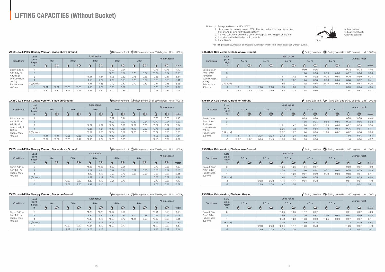
ZX55U-5A Cab Version, Blade above Ground Rating over-front Rating over-side or 360 degrees Unit: 1 000 kg
Conditions
Load point height
m
Load radiusAt max. reach
1.0 m �.0 m �.0 m �.0 m �.0 m
meter
Boom 2.85 mArm 1.69 mAdditional counterweight 200 kgRubber shoe 400 mm
4 *0.99 0.96 *0.78 *0.78 4.40
3 *1.03 0.95 0.79 0.66 *0.72 0.66 5.03
2 *1.61 1.42 1.10 0.92 0.78 0.65 0.70 0.59 5.34
1 1.61 1.32 1.05 0.88 0.76 0.64 0.68 0.57 5.41
0 (Ground) 1.56 1.27 1.02 0.85 0.75 0.62 0.70 0.58 5.26
-1 *1.81 *1.81 *2.28 *2.28 1.56 1.26 1.01 0.84 0.78 0.65 4.84
-2 *2.82 *2.82 *3.25 2.49 1.58 1.28 1.03 0.86 1.01 0.84 4.07
ZX55U-5A Cab Version, Blade on Ground Rating over-front Rating over-side or 360 degrees Unit: 1 000 kg
Conditions
Load point height
m
Load radiusAt max. reach
1.0 m �.0 m �.0 m �.0 m �.0 m
meter
Boom 2.85 mArm 1.69 mAdditional counterweight 200 kgRubber shoe 400 mm
4 *0.99 0.96 *0.78 *0.78 4.40
3 *1.03 0.95 *0.80 0.66 *0.72 0.66 5.03
2 *1.61 1.42 *1.24 0.92 *1.09 0.65 *0.72 0.59 5.34
1 *2.26 1.32 *1.49 0.88 *1.18 0.64 *0.76 0.57 5.41
0 (Ground) *2.52 1.27 *1.64 0.85 *1.23 0.62 *0.87 0.58 5.26
-1 *1.81 *1.81 *2.28 *2.28 *2.42 1.26 *1.62 0.84 *1.08 0.65 4.84
-2 *2.82 *2.82 *3.25 2.49 *1.96 1.28 *1.23 0.86 *1.18 0.84 4.07
ZX55U-5A Cab Version, Blade above Ground Rating over-front Rating over-side or 360 degrees Unit: 1 000 kg
Conditions
Load point height
m
Load radiusAt max. reach
1.0 m �.0 m �.0 m �.0 m �.0 m
meter
Boom 2.85 mArm 1.38 mRubber shoe 400 mm
3 *1.26 *1.26 1.04 0.87 0.80 0.67 4.69
2 1.56 1.28 1.00 0.84 0.71 0.60 0.70 0.59 5.03
1 1.47 1.20 0.97 0.80 0.70 0.59 0.68 0.57 5.11
0 (Ground) 1.44 1.17 0.94 0.78 0.70 0.59 4.94
-1 *2.68 2.28 1.44 1.17 0.94 0.78 0.81 0.67 4.49
-2 *2.69 2.33 1.47 1.20 1.12 0.92 3.61
ZX55U-5A Cab Version, Blade on Ground Rating over-front Rating over-side or 360 degrees Unit: 1 000 kg
Conditions
Load point height
m
Load radiusAt max. reach
1.0 m �.0 m �.0 m �.0 m �.0 m
meter
Boom 2.85 mArm 1.38 mRubber shoe 400 mm
3 *1.26 *1.26 *1.17 0.87 *0.91 0.67 4.69
2 *1.86 1.28 *1.36 0.84 *1.06 0.60 *0.91 0.59 5.03
1 *2.43 1.20 *1.58 0.80 *1.24 0.59 *0.97 0.57 5.11
0 (Ground) *2.56 1.17 *1.69 0.78 *1.13 0.59 4.94
-1 *2.68 2.28 *2.34 1.17 *1.58 0.78 *1.28 0.67 4.49
-2 *2.69 2.33 *1.73 1.20 *1.25 0.92 3.61
A: Load radiusB: Load point heightC: Lifting capacity
Notes: 1. Ratings are based on ISO 10567. 2. Lifting capacity does not exceed 75% of tipping load with the machine on firm, level ground or 87% full hydraulic capacity. 3. The load point is the center-line of the bucket pivot mounting pin on the arm. 4. *Indicates load limited by hydraulic capacity. 5. 0 m = Ground.
For lifting capacities, subtract bucket and quick hitch weight from lifting capacities without bucket.
A
B
C
LIFTING CAPACITIES (Without Bucket)
ZX55U-5A 4-Pillar Canopy Version, Blade above Ground Rating over-front Rating over-side or 360 degrees Unit: 1 000 kg
Conditions
Load point height
m
Load radiusAt max. reach
1.0 m �.0 m �.0 m �.0 m �.0 m
meter
Boom 2.85 mArm 1.69 mAdditional counterweight 200 kgRubber shoe 400 mm
4 *0.99 0.94 *0.78 *0.78 4.40
3 *1.03 0.92 0.76 0.64 *0.72 0.64 5.03
2 *1.61 1.37 1.06 0.89 0.75 0.63 0.68 0.57 5.34
1 1.56 1.27 1.02 0.85 0.73 0.62 0.65 0.55 5.41
0 (Ground) 1.51 1.23 0.99 0.82 0.72 0.60 0.67 0.56 5.26
-1 *1.81 *1.81 *2.28 *2.28 1.50 1.22 0.98 0.81 0.75 0.63 4.84
-2 *2.82 *2.82 3.17 2.41 1.53 1.24 1.00 0.83 0.98 0.81 4.07
ZX55U-5A 4-Pillar Canopy Version, Blade on Ground Rating over-front Rating over-side or 360 degrees Unit: 1 000 kg
Conditions
Load point height
m
Load radiusAt max. reach
1.0 m �.0 m �.0 m �.0 m �.0 m
meter
Boom 2.85 mArm 1.69 mAdditional counterweight 200 kgRubber shoe 400 mm
4 *0.99 0.94 *0.78 *0.78 4.40
3 *1.03 0.92 *0.80 0.64 *0.72 0.64 5.03
2 *1.61 1.37 *1.24 0.89 *1.09 0.63 *0.72 0.57 5.34
1 *2.26 1.27 *1.49 0.85 *1.18 0.62 *0.76 0.55 5.41
0 (Ground) *2.52 1.23 *1.64 0.82 *1.23 0.60 *0.87 0.56 5.26
-1 *1.81 *1.81 *2.28 *2.28 *2.42 1.22 *1.62 0.81 *1.08 0.63 4.84
-2 *2.82 *2.82 *3.25 2.41 *1.96 1.24 *1.23 0.83 *1.18 0.81 4.07
ZX55U-5A 4-Pillar Canopy Version, Blade above Ground Rating over-front Rating over-side or 360 degrees Unit: 1 000 kg
Conditions
Load point height
m
Load radiusAt max. reach
1.0 m �.0 m �.0 m �.0 m �.0 m
meter
Boom 2.85 mArm 1.38 mRubber shoe 400 mm
3 *1.26 *1.26 1.00 0.84 0.77 0.65 4.69
2 1.51 1.24 0.97 0.81 0.69 0.58 0.68 0.57 5.03
1 1.42 1.15 0.93 0.77 0.67 0.56 0.65 0.55 5.11
0 (Ground) 1.39 1.12 0.91 0.75 0.68 0.57 4.94
-1 *2.68 2.20 1.39 1.13 0.91 0.75 0.78 0.65 4.49
-2 *2.69 2.25 1.42 1.16 1.08 0.89 3.61
ZX55U-5A 4-Pillar Canopy Version, Blade on Ground Rating over-front Rating over-side or 360 degrees Unit: 1 000 kg
Conditions
Load point height
m
Load radiusAt max. reach
1.0 m �.0 m �.0 m �.0 m �.0 m
meter
Boom 2.85 mArm 1.38 mRubber shoe 400 mm
3 *1.26 *1.26 *1.17 0.84 *0.91 0.65 4.69
2 *1.86 1.24 *1.36 0.81 *1.06 0.58 *0.91 0.57 5.03
1 *2.43 1.15 *1.58 0.77 *1.24 0.56 *0.97 0.55 5.11
0 (Ground) *2.56 1.12 *1.69 0.75 *1.13 0.57 4.94
-1 *2.68 2.20 *2.34 1.13 *1.58 0.75 *1.28 0.65 4.49
-2 *2.69 2.25 *1.73 1.16 *1.25 0.89 3.61
1� 1�
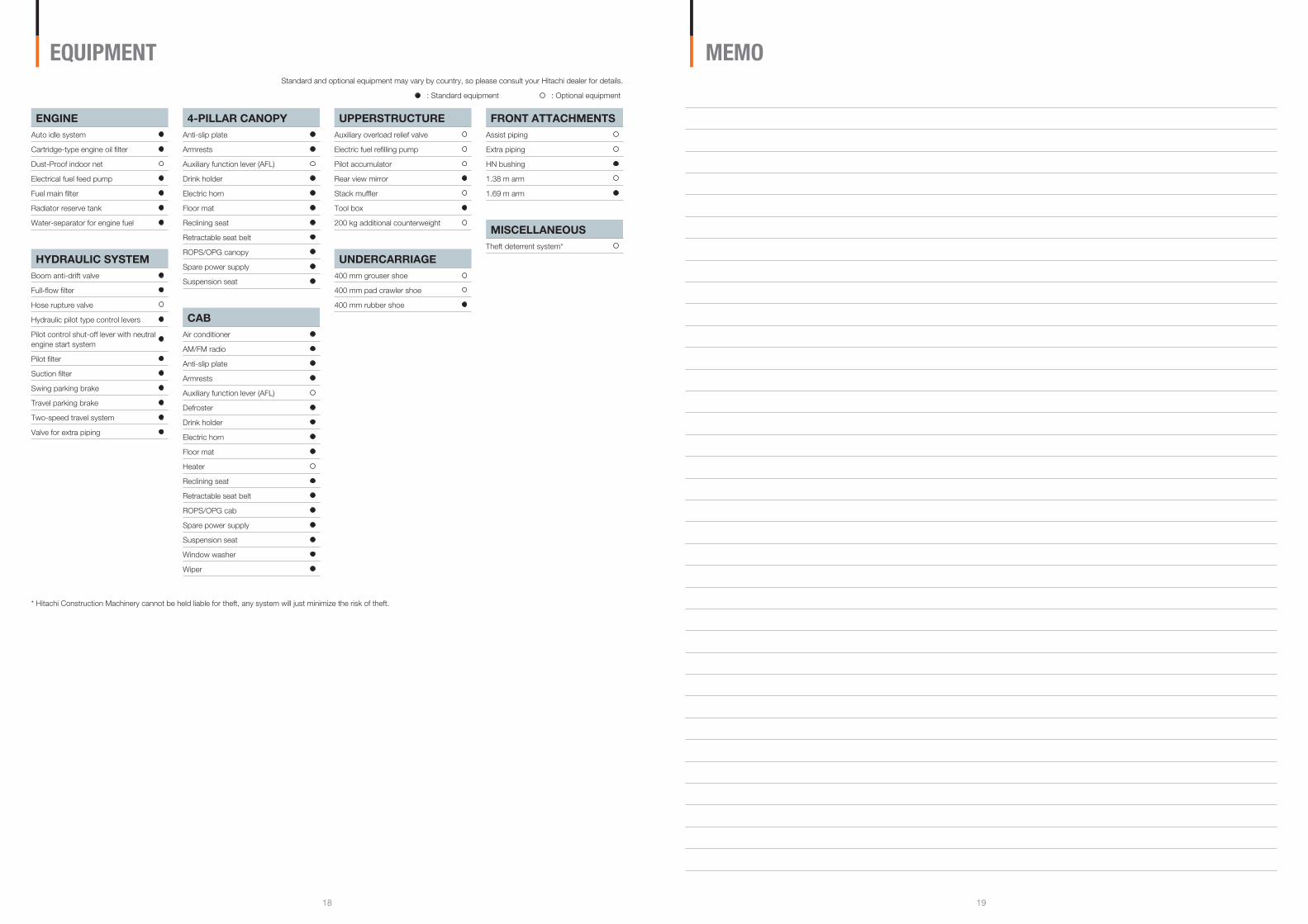
FRONT ATTACHMENTSAssist piping
Extra piping
HN bushing
1.38 m arm
1.69 m arm
MISCELLANEOUSTheft deterrent system*
ENGINEAuto idle system
Cartridge-type engine oil filter
Dust-Proof indoor net
Electrical fuel feed pump
Fuel main filter
Radiator reserve tank
Water-separator for engine fuel
HYDRAULIC SYSTEMBoom anti-drift valve
Full-flow filter
Hose rupture valve
Hydraulic pilot type control levers
Pilot control shut-off lever with neutral engine start system
Pilot filter
Suction filter
Swing parking brake
Travel parking brake
Two-speed travel system
Valve for extra piping
4-PILLAR CANOPYAnti-slip plate
Armrests
Auxiliary function lever (AFL)
Drink holder
Electric horn
Floor mat
Reclining seat
Retractable seat belt
ROPS/OPG canopy
Spare power supply
Suspension seat
CABAir conditioner
AM/FM radio
Anti-slip plate
Armrests
Auxiliary function lever (AFL)
Defroster
Drink holder
Electric horn
Floor mat
Heater
Reclining seat
Retractable seat belt
ROPS/OPG cab
Spare power supply
Suspension seat
Window washer
Wiper
UPPERSTRUCTUREAuxiliary overload relief valve
Electric fuel refilling pump
Pilot accumulator
Rear view mirror
Stack muffler
Tool box
200 kg additional counterweight
UNDERCARRIAGE400 mm grouser shoe
400 mm pad crawler shoe
400 mm rubber shoe
: Standard equipment : Optional equipment
EQUIPMENT
* Hitachi Construction Machinery cannot be held liable for theft, any system will just minimize the risk of theft.
Standard and optional equipment may vary by country, so please consult your Hitachi dealer for details.
MEMO
1�.01 (SA/KA,MT�)KS-EN239Hitachi Construction Machinery Co., Ltd.www.hitachi-c-m.com
These specifications are subject to change without notice.Illustrations and photos show the standard models, and may or may not include optional equipment,accessories, and all standard equipment with some differences in color and features.Before use, read and understand the Operator’s Manual for proper operation.
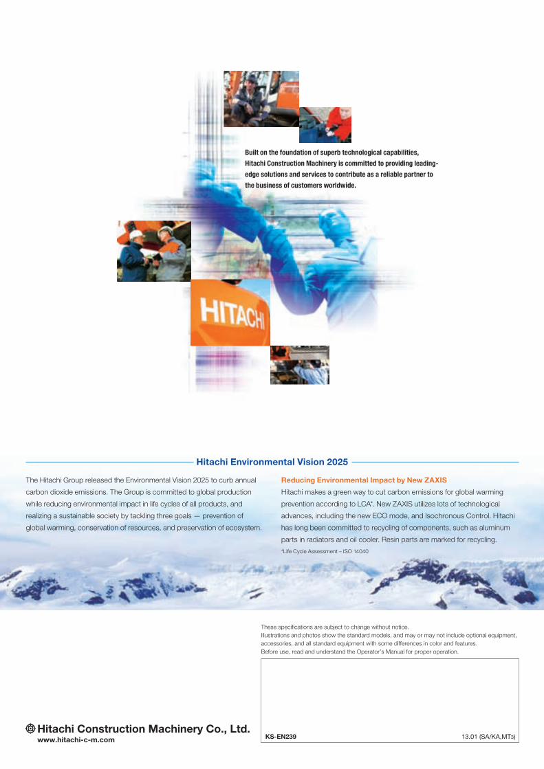
Built on the foundation of superb technological capabilities,
Hitachi Construction Machinery is committed to providing leading-
edge solutions and services to contribute as a reliable partner to
the business of customers worldwide.
Reducing Environmental Impact by New ZAXIS
Hitachi makes a green way to cut carbon emissions for global warming
prevention according to LCA*. New ZAXIS utilizes lots of technological
advances, including the new ECO mode, and Isochronous Control. Hitachi
has long been committed to recycling of components, such as aluminum
parts in radiators and oil cooler. Resin parts are marked for recycling.
*Life Cycle Assessment – ISO 14040
The Hitachi Group released the Environmental Vision 2025 to curb annual
carbon dioxide emissions. The Group is committed to global production
while reducing environmental impact in life cycles of all products, and
realizing a sustainable society by tackling three goals — prevention of
global warming, conservation of resources, and preservation of ecosystem.
Hitachi Environmental Vision 2025