Embed Size (px)
Citation preview
EX-6 series
HYDRAULIC EXCAVATOR
Illustrations show diesel engine type.
EX2500-6 with Diesel Engine Engine Gross Power : 1 044 kW (1 400 HP) Operating Weight : Loading Shovel : 249 000 kg Backhoe : 248 000 kg
EX2500E-6 with Electric Motor Power Output : 860 kW Operating Weight : Loading Shovel : 246 000 kg
Bucket Capacity Loading Shovel Bucket : Heaped : 15.0 - 16.5 m3
Backhoe Bucket : SAE, PCSA Heaped : 15.0 m3
CECE Heaped : 13.2 m3
H
K C
F
G
JAB
EE'
D&D'
I
A Distance between tumblers 6 120 mmB Undercarriage length 7 870 mmC Counterweight clearance 2 140 mmD Rear-end swing radius 6 290 mm D' Rear-end length 6 190 mmE Overall width of upperstructure 7 430 mm
E' Overall width 7 560 mmF Overall height of cab 7 250 mmG Min. ground clearance 800 mmH Track gauge 5 000 mmI Track shoe width 1 000 mmJ Undercarriage width 6 000 mmK Track height 2 060 mm
2
SPECIFICATIONS
Cylinder DimensionsLoading shovel
Quan. Bore Rod diameterBoom 2 310 mm 230 mmArm 1 280 mm 210 mmBucket 2 250 mm 180 mmDump 2 215 mm 130 mmLevel 1 310 mm 230 mm
BackhoeQuan. Bore Rod diameter
Boom 2 310 mm 230 mmArm 1 280 mm 200 mmBucket 1 230 mm 170 mm
ENGINE
Model ...................................... Cummins QSKTA50-CEType ........................................ Water-cooled, 4-cycle, 16-cylinder,
turbo-charged and after-cooled, direct injection chamber-type diesel engine
Rated powerSAE J1995, gross ................ 1 044 kW (1 400 HP) at 1 800 min-¹ (rpm)Net ....................................... 994 kW (1 333 HP) at 1 800 min-¹ (rpm)
Maximum torque ..................... 6 379 N.m (651 kgf·m) at 1 300 min-¹ (rpm)Piston displacement ................ 50.0 LBore and stroke ....................... 159 mm x 159 mmStarting system ....................... 24 V electric motorBatteries .................................. 4 x 12 V , 4 x 220 AHCold starting ............................ Ether aided
HYDRAULIC SYSTEM
Hitachi's ETS (Electronic Total control System) can achieve maximum job efficiency by reducing fuel consumption and noise levels, while maximizing productivity through the optimization of engine-pump functions with excellent controllability increasing operator comfort.
• E-P Control (Computer-aided Engine-Pump Control system) Main pumps regulated by electric engine speed sensing control system.
• OHS (Optimum Hydraulic System)6 main pumps and 3 valves system enable both independent and combined operations of all functions.
• FPS (Fuel-saving Pump System)FPS minimizes energy loss with superior performance in fine control.
• Auto-idling system for saving fuel and reducing noise.• Hydraulic drive cooling-fan system for oil cooler.• Forced-lubrication and forced-cooling pump drive system.
EX2500-6
Hydraulic FiltersAll hydraulic circuits have high-quality hydraulic filters for protection against oil contamination and longer life of hydraulic components.
These filters are centralized in arrangement for facilitating maintenance.
Qty.Full flow filter 3 10 µmHigh pressure strainer 6 80 meshes(In main & swing pump delivery line)Drain filter 1 10 µm(For all plunger type pumps & motors)By-pass filter 1 5 µm(In oil cooler by-pass line)Pilot filter 1 10 µm
Relief Valve SettingsImplement circuit ........................................... 29.4 MPa (300 kgf/cm²)Swing circuit .................................................. 29.4 MPa (300 kgf/cm²)Travel circuit .................................................. 29.4 MPa (300 kgf/cm²)Pilot circuit .................................................... 3.9 MPa ( 40 kgf/cm²)
Hydraulic CylindersHigh-strength piston rods and tubes adopted. Cylinder cushion mechanisms are provided for boom, arm, bucket and dump cylinders.Bucket cylinders of loading shovel are provided with protector.
Main pumps .............. 6 variable-displacement, axial piston pumps for front attachment, travel and swing
Max. oil flow ............. 4 X 375 L/min, 2 X 425 L/minPilot pump ................ 1 gear pump
Max. oil flow ............. 108 L/min
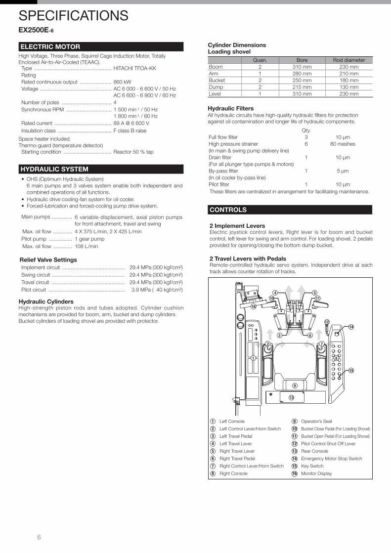
CONTROLS
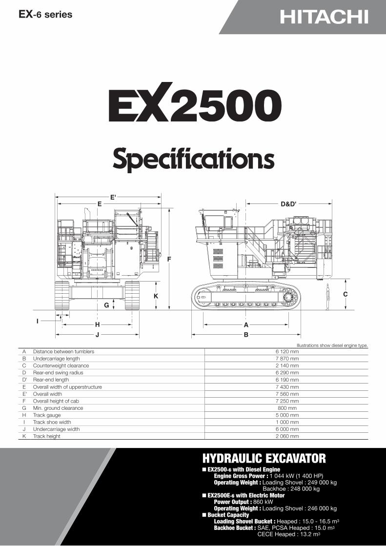
2 Implement LeversElectric joystick control levers. Right lever is for boom and bucket control, left lever for swing and arm control. For loading shovel, 2 pedals provided for opening/closing the bottom dump bucket.
2 Travel Levers with PedalsRemote-controlled hydraulic servo system. Independent drive at each track allows counter rotation of tracks.
1 Left Console 10 Bucket Close Pedal (For Loading Shovel)
2 Left Control Lever/Horn Switch 11 Bucket Open Pedal (For Loading Shovel)
3 Left Travel Pedal 12 Pilot Control Shut-Off Lever
4 Left Travel Lever 13 Rear Console
5 Right Travel Lever 14 Emergency Engine Stop Switch
6 Right Travel Pedal 15 Engine Speed Control Dial
7 Right Control Lever/Horn Switch 16 Key Switch
8 Right Console 17 Monitor Display
9 Operator’s Seat
1 8
9
13
2 7
17
12
16
15
14
115
63
104
3
Swing Mechanism2 high-torque, axial-piston motors with two-stage planetary gear bathed in oil. Swing circle with dirt seals is a heavy-duty, triple-row, cylindrical roller bearing. Induction-hardened internal swing circle gear and pinion immersed in lubricant. Parking brake of spring-set/hydraulic-released disc type. This parking brake is manually releasable.
Swing speed ................................................................. 3.8 min-¹ (rpm)
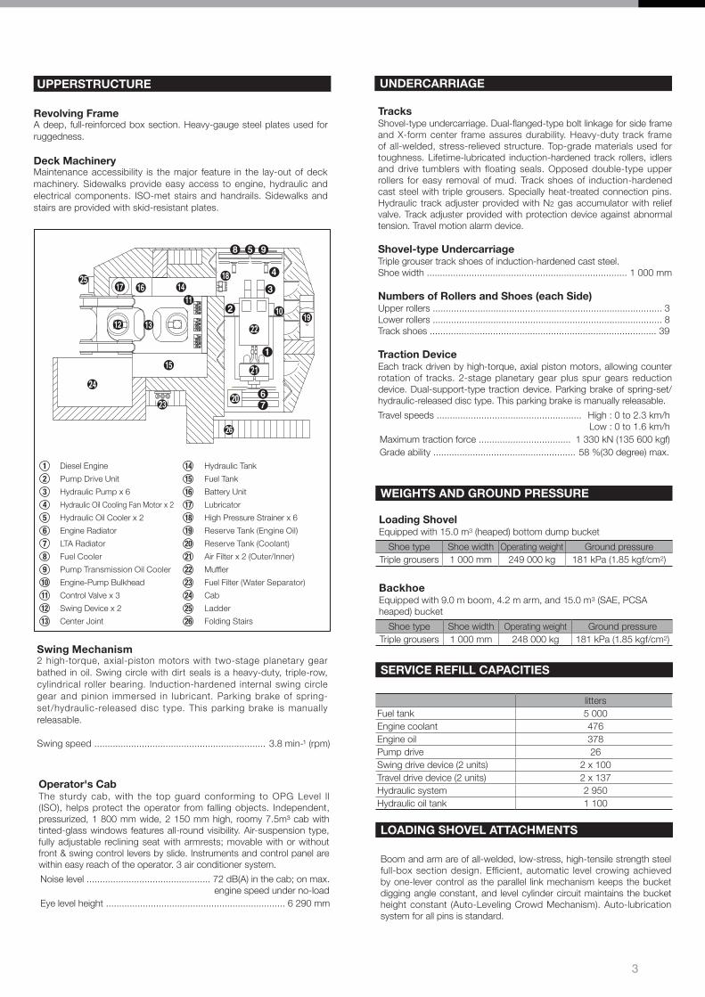
UPPERSTRUCTURE
Revolving FrameA deep, full-reinforced box section. Heavy-gauge steel plates used for ruggedness.
Deck MachineryMaintenance accessibility is the major feature in the lay-out of deck machinery. Sidewalks provide easy access to engine, hydraulic and electrical components. ISO-met stairs and handrails. Sidewalks and stairs are provided with skid-resistant plates.
1 Diesel Engine 14 Hydraulic Tank
2 Pump Drive Unit 15 Fuel Tank
3 Hydraulic Pump x 6 16 Battery Unit
4 Hydraulic Oil Cooling Fan Motor x 2 17 Lubricator
5 Hydraulic Oil Cooler x 2 18 High Pressure Strainer x 6
6 Engine Radiator 19 Reserve Tank (Engine Oil)
7 LTA Radiator 20 Reserve Tank (Coolant)
8 Fuel Cooler 21 Air Filter x 2 (Outer/Inner)
9 Pump Transmission Oil Cooler 22 Muffler
10 Engine-Pump Bulkhead 23 Fuel Filter (Water Separator)
11 Control Valve x 3 24 Cab
12 Swing Device x 2 25 Ladder
13 Center Joint 26 Folding Stairs
Operator's CabThe sturdy cab, with the top guard conforming to OPG Level ll (ISO), helps protect the operator from falling objects. Independent, pressurized, 1 800 mm wide, 2 150 mm high, roomy 7.5m³ cab with tinted-glass windows features all-round visibility. Air-suspension type, fully adjustable reclining seat with armrests; movable with or without front & swing control levers by slide. Instruments and control panel are within easy reach of the operator. 3 air conditioner system.
Noise level ............................................... 72 dB(A) in the cab; on max. engine speed under no-loadEye level height .................................................................... 6 290 mm
WEIGHTS AND GROUND PRESSURE
Loading ShovelEquipped with 15.0 m3 (heaped) bottom dump bucket
Shoe type Shoe width Operating weight Ground pressureTriple grousers 1 000 mm 249 000 kg 181 kPa (1.85 kgf/cm2)
BackhoeEquipped with 9.0 m boom, 4.2 m arm, and 15.0 m3 (SAE, PCSA heaped) bucket
Shoe type Shoe width Operating weight Ground pressureTriple grousers 1 000 mm 248 000 kg 181 kPa (1.85 kgf/cm2)
SERVICE REFILL CAPACITIES
littersFuel tank 5 000Engine coolant 476Engine oil 378Pump drive 26Swing drive device (2 units) 2 x 100Travel drive device (2 units) 2 x 137Hydraulic system 2 950Hydraulic oil tank 1 100
UNDERCARRIAGE
TracksShovel-type undercarriage. Dual-flanged-type bolt linkage for side frame and X-form center frame assures durability. Heavy-duty track frame of all-welded, stress-relieved structure. Top-grade materials used for toughness. Lifetime-lubricated induction-hardened track rollers, idlers and drive tumblers with floating seals. Opposed double-type upper rollers for easy removal of mud. Track shoes of induction-hardened cast steel with triple grousers. Specially heat-treated connection pins. Hydraulic track adjuster provided with N2 gas accumulator with relief valve. Track adjuster provided with protection device against abnormal tension. Travel motion alarm device.
Shovel-type UndercarriageTriple grouser track shoes of induction-hardened cast steel.Shoe width ............................................................................ 1 000 mm
Numbers of Rollers and Shoes (each Side)Upper rollers ....................................................................................... 3Lower rollers ....................................................................................... 8Track shoes ...................................................................................... 39
Traction DeviceEach track driven by high-torque, axial piston motors, allowing counter rotation of tracks. 2-stage planetary gear plus spur gears reduction device. Dual-support-type traction device. Parking brake of spring-set/hydraulic-released disc type. This parking brake is manually releasable.
Travel speeds ....................................................... High : 0 to 2.3 km/h Low : 0 to 1.6 km/h Maximum traction force ................................... 1 330 kN (135 600 kgf)Grade ability ...................................................... 58 %(30 degree) max.
LOADING SHOVEL ATTACHMENTS
Boom and arm are of all-welded, low-stress, high-tensile strength steel full-box section design. Efficient, automatic level crowing achieved by one-lever control as the parallel link mechanism keeps the bucket digging angle constant, and level cylinder circuit maintains the bucket height constant (Auto-Leveling Crowd Mechanism). Auto-lubrication system for all pins is standard.
4
SPECIFICATIONS
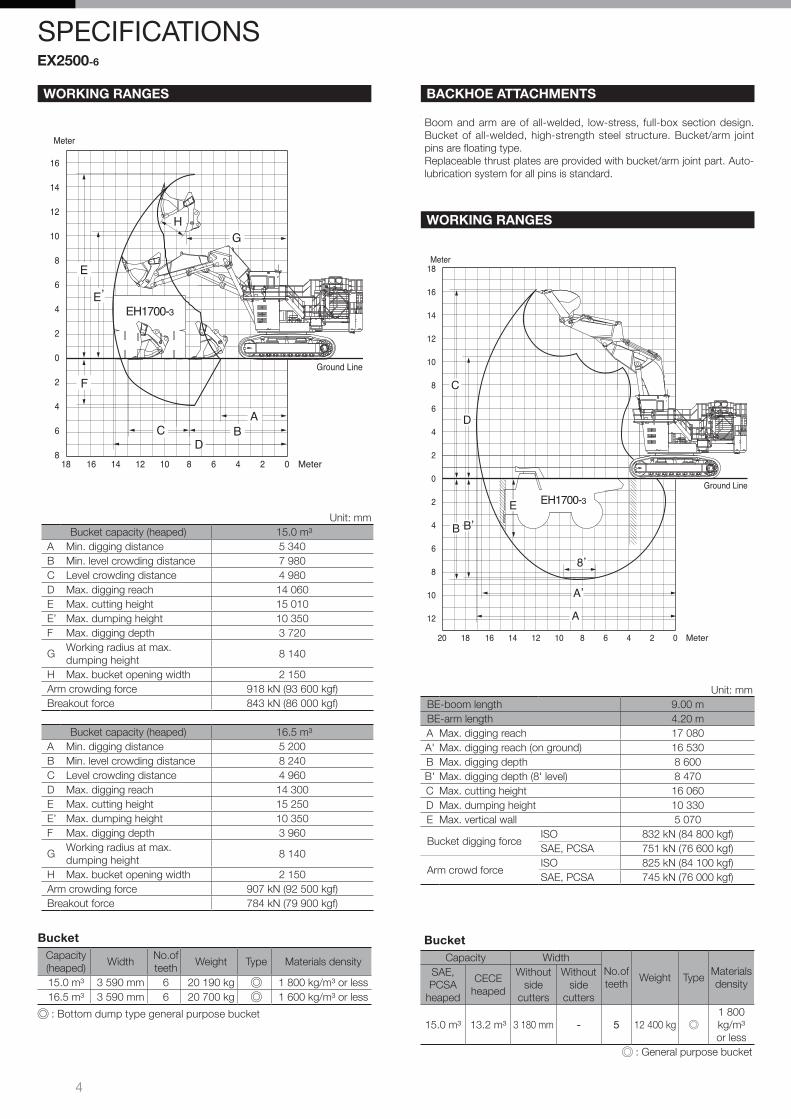
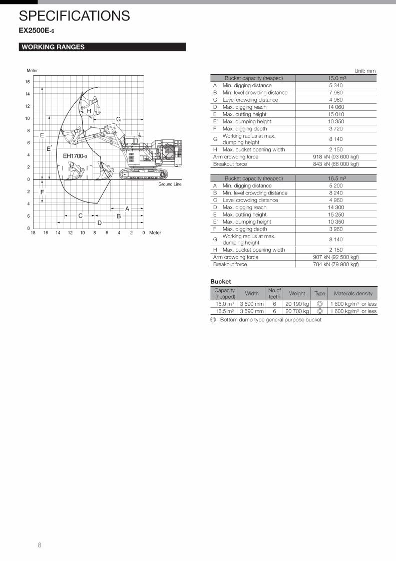
WORKING RANGES
Unit: mmBucket capacity (heaped) 15.0 m³
A Min. digging distance 5 340B Min. level crowding distance 7 980C Level crowding distance 4 980D Max. digging reach 14 060E Max. cutting height 15 010E’ Max. dumping height 10 350F Max. digging depth 3 720
GWorking radius at max. dumping height
8 140
H Max. bucket opening width 2 150Arm crowding force 918 kN (93 600 kgf)Breakout force 843 kN (86 000 kgf)
Meter
Ground Line
16
14
12
10
8
6
4
2
0
2
4
6
801618 14 12 10 8 6 4 2 Meter
ABC
D
F
E,
E
EH1700-3
HG
Bucket capacity (heaped) 16.5 m³A Min. digging distance 5 200B Min. level crowding distance 8 240C Level crowding distance 4 960D Max. digging reach 14 300E Max. cutting height 15 250E’ Max. dumping height 10 350F Max. digging depth 3 960
GWorking radius at max. dumping height
8 140
H Max. bucket opening width 2 150Arm crowding force 907 kN (92 500 kgf)Breakout force 784 kN (79 900 kgf)
BucketCapacity (heaped)
WidthNo.of teeth
Weight Type Materials density
15.0 m³ 3 590 mm 6 20 190 kg 1 800 kg/m³ or less16.5 m³ 3 590 mm 6 20 700 kg 1 600 kg/m³ or less
: Bottom dump type general purpose bucket
BACKHOE ATTACHMENTS
Boom and arm are of all-welded, low-stress, full-box section design. Bucket of all-welded, high-strength steel structure. Bucket/arm joint pins are floating type.Replaceable thrust plates are provided with bucket/arm joint part. Auto-lubrication system for all pins is standard.
WORKING RANGES
Unit: mmBE-boom length 9.00 mBE-arm length 4.20 mA Max. digging reach 17 080A' Max. digging reach (on ground) 16 530B Max. digging depth 8 600 B' Max. digging depth (8' level) 8 470C Max. cutting height 16 060D Max. dumping height 10 330E Max. vertical wall 5 070
Bucket digging forceISO 832 kN (84 800 kgf)SAE, PCSA 751 kN (76 600 kgf)
Arm crowd forceISO 825 kN (84 100 kgf)SAE, PCSA 745 kN (76 000 kgf)
EH1700-3
Meter18
16
14
12
10
8
6
4
2
0
2
4
6
8
10
12
0161820 14 12 10 8 6 4 2 Meter
D
E
B,
C
A
A,
8,
B
Ground Line
BucketCapacity Width
No.ofteeth
Weight TypeMaterials density
SAE, PCSA
heaped
CECE heaped
Withoutside
cutters
Withoutside
cutters
15.0 m³ 13.2 m³ 3 180 mm - 5 12 400 kg1 800 kg/m³ or less
: General purpose bucket
EX2500-6

5
ENGINE• 140 A alternator• Heavy-duty type air cleaner with dust
ejector• Cartridge-type engine oil filter• Cartridge-type engine oil bypass filter• Cartridge-type fuel filter • Water filter• Radiator reserve tank• Fan guard• Isolation-mounted engine• Pre-lubrication system• Auto-idle system• Emergency engine stop system
HYDRAULIC SYSTEM• E-P control system• OHS (Optimum Hydraulic System)• FPS (Fuel-saving Pump System)• Hydraulic drive cooling-fan system• Forced-lubrication and forced cooling
pump drive system• Control valve with main relief valve• Suction filter• Full-flow filter• Bypass filter• Pilot filter • Drain filter• High-pressure strainer
CABThe sturdy cab, with the top guard conforming to OPG Level ll (ISO), helps protect the operator from falling objects.Fluid-filled elastic mounts.Laminated glass windshield. Reinforced/tinted (bronze color) glass side and rear windows. Parallel-link-type intermittent windshield wiper. Windshield washer. Ad justab le rec l in ing seat wi th a i r suspension. Footrest. Air horn with electric compressor. Auto-tuning AM-FM radio with digital clock. Seat belt. Storage spaces. Floor mat. Air conditioner with defroster. Rearview mirror. Evacuation hammer. Emergency escape device. Trainer's seat. Pilot control shut-off lever.
MONITOR SYSTEMS• Meters:
Hourmeter. Fuel gauge. Hydraulic oil temperature gauge. Engine coolant temperature gauge. Tachometer.Engine oil pressure gauge. Engine oil temperature gauge.Battery voltage gauge. Ambient temperature.
• Pilot lamps (Green):Pre-lubrication. Auto-Idle. Travel Mode.
• Warning lamps (Red):Alternator. Engine stop. Coolant overheat. Hydraulic oil level. Auto-lubrication. Fast-filling. Tension. Electric lever. Emergency engine stop. Top valve. Engine over run. Coolant level. Engine oil pressure. Pump transmission oil level indicator.
• Warning lamp (Yellow):Exhaust temperature. Fuel temperature. Engine warning. Hydraulic oil overheat. Stairway position. Electrical equipment box. Pump contamination. Air cleaner restriction.
• Alarm buzzers:Overheat. Engine coolant pressure. Engine coolant level. Fuel temperature. Engine oil pressure. Engine oil temperature. Air intake manifold temperature. Crank case pressure. Pump transmission oil level. Hydraulic oil level. Stop valve close. Fast-filling system panel position. Ladder position. Electric lever fault.
DATA LOGGING SYSTEM• DLU(Data-logging unit) continuously
records performance of the engine and the hydraulic system. The record can be downloaded by PC and PDA.
LIGHTS• 6 working lights. 2 entrance lights.
3 maintenance lights. 2 cab lights.
UPPERSTRUCTURE• Lockable machine covers• 30 000 kg counterweight• Hydraulic drive grease gun with hose
reel• Folding stairs with wide steps• Swing parking brake• Engine oil reserve system
UNDERCARRIAGE• Travel parking brake• Travel motion alarm device• Hydraulic track adjuster with N2 gas
accumulator and relief valve• 1 000 mm triple grouser shoes
MISCELLANEOUS• Standard tool kit• Stairs and handrails (Meeting ISO)• Recirculation air filter for air conditioner• Ventilation air filter for air conditioner• 12 V power terminal board• Stop valve for transport and reassembly• Auto-lubrication (Lincoln) for front-
attachment pins, swing bearing, and center joint
FAST-FILLING SYSTEM• Fast-filling system (Wiggins) for fuel, hydraulic oil, coolant, swing device oil, pump transmission oil, engine oil, and grease (couplers not included).
OPTIONAL EQUIPMENT Optional equipment may vary by country, so please consult your Hitachi dealer for details.
• Fast-filling couplers• High brightness working lights• Back and right side color monitor camera• Cold weather package
• Satellite data transmitting system• Travel motor guard• Travel device guard• Lower roller guard
STANDARD EQUIPMENT Standard equipment may vary by country, so please consult your Hitachi dealer for details.
EQUIPMENT
6
SPECIFICATIONS
Cylinder DimensionsLoading shovel
Quan. Bore Rod diameterBoom 2 310 mm 230 mmArm 1 280 mm 210 mmBucket 2 250 mm 180 mmDump 2 215 mm 130 mmLevel 1 310 mm 230 mm
ELECTRIC MOTORHigh Voltage, Three Phase, Squirrel Cage Induction Motor, Totally Enclosed Air-to-Air-Cooled (TEAAC).Type ..................................................... HITACHI TFOA-KKRatingRated continuous output ...................... 860 kWVoltage ................................................. AC 6 000 - 6 600 V / 50 Hz
AC 6 600 - 6 900 V / 60 HzNumber of poles .................................. 4Synchronous RPM ............................... 1 500 min-1 / 50 Hz
1 800 min-1 / 60 HzRated current ....................................... 89 A @ 6 600 VInsulation class ..................................... F class B raise
Space heater included. Thermo-guard (temperature detector)Starting condition ................................. Reactor 50 % tap
HYDRAULIC SYSTEM• OHS (Optimum Hydraulic System)
6 main pumps and 3 valves system enable both independent and combined operations of all functions.
• Hydraulic drive cooling-fan system for oil cooler.• Forced-lubrication and forced-cooling pump drive system.
EX2500E-6
Hydraulic FiltersAll hydraulic circuits have high-quality hydraulic filters for protection against oil contamination and longer life of hydraulic components.
These filters are centralized in arrangement for facilitating maintenance.
Qty.Full flow filter 3 10 µmHigh pressure strainer 6 80 meshes(In main & swing pump delivery line)Drain filter 1 10 µm(For all plunger type pumps & motors)By-pass filter 1 5 µm(In oil cooler by-pass line)Pilot filter 1 10 µm
Relief Valve SettingsImplement circuit ........................................... 29.4 MPa (300 kgf/cm²)Swing circuit .................................................. 29.4 MPa (300 kgf/cm²)Travel circuit .................................................. 29.4 MPa (300 kgf/cm²)Pilot circuit .................................................... 3.9 MPa ( 40 kgf/cm²)
Hydraulic CylindersHigh-strength piston rods and tubes adopted. Cylinder cushion mechanisms are provided for boom, arm, bucket and dump cylinders.Bucket cylinders of loading shovel are provided with protector.
Main pumps .............. 6 variable-displacement, axial piston pumps for front attachment, travel and swing
Max. oil flow ............. 4 X 375 L/min, 2 X 425 L/minPilot pump ................ 1 gear pump
Max. oil flow ............. 108 L/min
CONTROLS
2 Implement LeversElectric joystick control levers. Right lever is for boom and bucket control, left lever for swing and arm control. For loading shovel, 2 pedals provided for opening/closing the bottom dump bucket.
2 Travel Levers with PedalsRemote-controlled hydraulic servo system. Independent drive at each track allows counter rotation of tracks.
1 Left Console 9 Operator’s Seat
2 Left Control Lever/Horn Switch 10 Bucket Close Pedal (For Loading Shovel)
3 Left Travel Pedal 11 Bucket Open Pedal (For Loading Shovel)
4 Left Travel Lever 12 Pilot Control Shut-Off Lever
5 Right Travel Lever 13 Rear Console
6 Right Travel Pedal 14 Emergency Motor Stop Switch
7 Right Control Lever/Horn Switch 15 Key Switch
8 Right Console 16 Monitor Display
1 8
9
13
2 7
16
12
15
14
115
63
104
�
Swing Mechanism2 high-torque, axial-piston motors with two-stage planetary gear bathed in oil. Swing circle with dirt seals is a heavy-duty, triple-row, cylindrical roller bearing. Induction-hardened internal swing circle gear and pinion immersed in lubricant. Parking brake of spring-set/hydraulic-released disc type. This parking brake is manually releasable.
Swing speed ................................................................. 3.6 min-¹ (rpm)
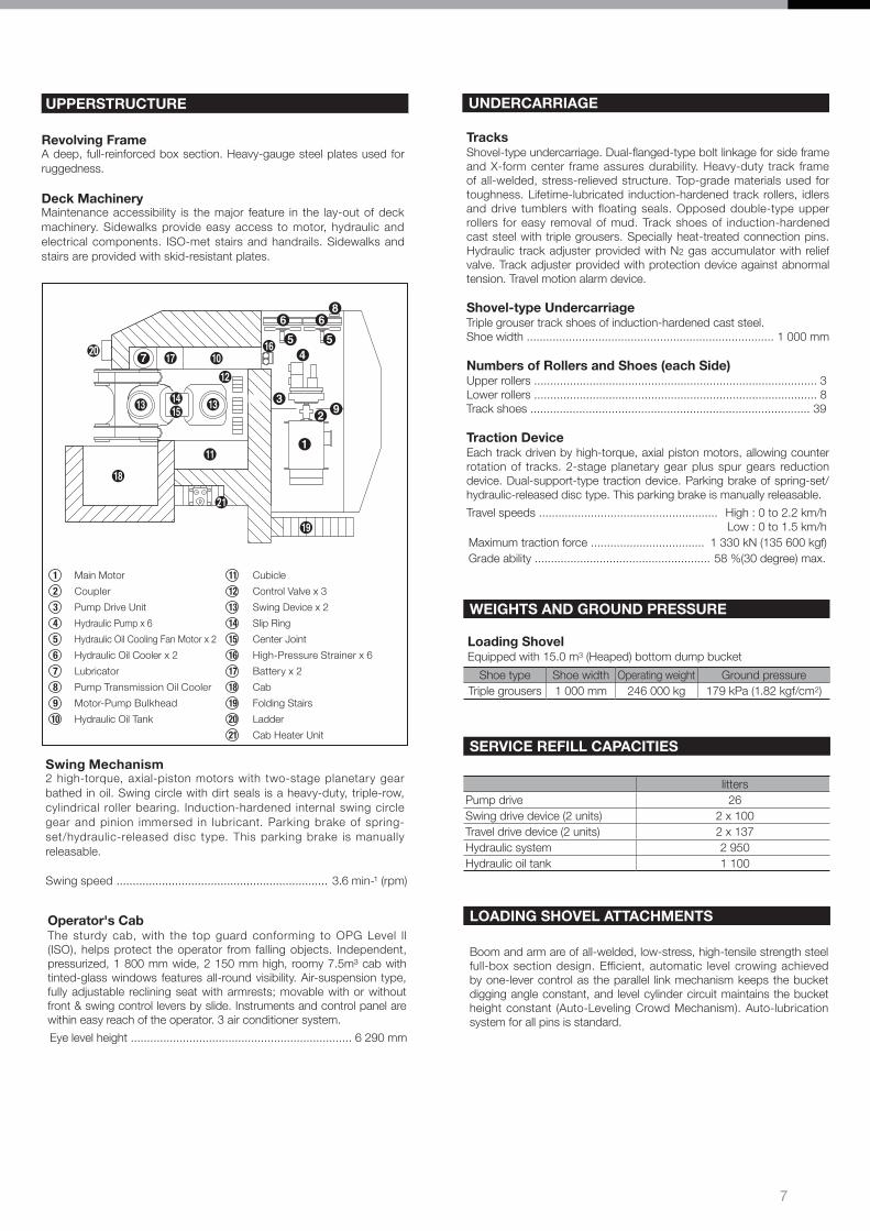
UPPERSTRUCTURE
Revolving FrameA deep, full-reinforced box section. Heavy-gauge steel plates used for ruggedness.
Deck MachineryMaintenance accessibility is the major feature in the lay-out of deck machinery. Sidewalks provide easy access to motor, hydraulic and electrical components. ISO-met stairs and handrails. Sidewalks and stairs are provided with skid-resistant plates.
1 Main Motor 11 Cubicle
2 Coupler 12 Control Valve x 3
3 Pump Drive Unit 13 Swing Device x 2
4 Hydraulic Pump x 6 14 Slip Ring
5 Hydraulic Oil Cooling Fan Motor x 2 15 Center Joint
6 Hydraulic Oil Cooler x 2 16 High-Pressure Strainer x 6
7 Lubricator 17 Battery x 2
8 Pump Transmission Oil Cooler 18 Cab
9 Motor-Pump Bulkhead 19 Folding Stairs
10 Hydraulic Oil Tank 20 Ladder
21 Cab Heater Unit
Operator's CabThe sturdy cab, with the top guard conforming to OPG Level ll (ISO), helps protect the operator from falling objects. Independent, pressurized, 1 800 mm wide, 2 150 mm high, roomy 7.5m³ cab with tinted-glass windows features all-round visibility. Air-suspension type, fully adjustable reclining seat with armrests; movable with or without front & swing control levers by slide. Instruments and control panel are within easy reach of the operator. 3 air conditioner system.
Eye level height .................................................................... 6 290 mm
WEIGHTS AND GROUND PRESSURE
Loading ShovelEquipped with 15.0 m3 (Heaped) bottom dump bucket
Shoe type Shoe width Operating weight Ground pressureTriple grousers 1 000 mm 246 000 kg 179 kPa (1.82 kgf/cm2)
SERVICE REFILL CAPACITIES
littersPump drive 26Swing drive device (2 units) 2 x 100Travel drive device (2 units) 2 x 137Hydraulic system 2 950Hydraulic oil tank 1 100
UNDERCARRIAGE
TracksShovel-type undercarriage. Dual-flanged-type bolt linkage for side frame and X-form center frame assures durability. Heavy-duty track frame of all-welded, stress-relieved structure. Top-grade materials used for toughness. Lifetime-lubricated induction-hardened track rollers, idlers and drive tumblers with floating seals. Opposed double-type upper rollers for easy removal of mud. Track shoes of induction-hardened cast steel with triple grousers. Specially heat-treated connection pins. Hydraulic track adjuster provided with N2 gas accumulator with relief valve. Track adjuster provided with protection device against abnormal tension. Travel motion alarm device.
Shovel-type UndercarriageTriple grouser track shoes of induction-hardened cast steel.Shoe width ............................................................................ 1 000 mm
Numbers of Rollers and Shoes (each Side)Upper rollers ....................................................................................... 3Lower rollers ....................................................................................... 8Track shoes ...................................................................................... 39
Traction DeviceEach track driven by high-torque, axial piston motors, allowing counter rotation of tracks. 2-stage planetary gear plus spur gears reduction device. Dual-support-type traction device. Parking brake of spring-set/hydraulic-released disc type. This parking brake is manually releasable.
Travel speeds ....................................................... High : 0 to 2.2 km/h Low : 0 to 1.5 km/h Maximum traction force ................................... 1 330 kN (135 600 kgf)Grade ability ...................................................... 58 %(30 degree) max.
LOADING SHOVEL ATTACHMENTS
Boom and arm are of all-welded, low-stress, high-tensile strength steel full-box section design. Efficient, automatic level crowing achieved by one-lever control as the parallel link mechanism keeps the bucket digging angle constant, and level cylinder circuit maintains the bucket height constant (Auto-Leveling Crowd Mechanism). Auto-lubrication system for all pins is standard.
8
SPECIFICATIONS
WORKING RANGES
Meter
16
14
12
10
8
6
4
2
0
2
4
6
801618 14 12 10 8 6 4 2 Meter
AB
D
F
E,
E
C
EH1700-3
HG
Ground Line
Unit: mmBucket capacity (heaped) 15.0 m³
A Min. digging distance 5 340B Min. level crowding distance 7 980C Level crowding distance 4 980D Max. digging reach 14 060E Max. cutting height 15 010E’ Max. dumping height 10 350F Max. digging depth 3 720
GWorking radius at max. dumping height
8 140
H Max. bucket opening width 2 150Arm crowding force 918 kN (93 600 kgf)Breakout force 843 kN (86 000 kgf)
Bucket capacity (heaped) 16.5 m³A Min. digging distance 5 200B Min. level crowding distance 8 240C Level crowding distance 4 960D Max. digging reach 14 300E Max. cutting height 15 250E’ Max. dumping height 10 350F Max. digging depth 3 960
GWorking radius at max. dumping height
8 140
H Max. bucket opening width 2 150Arm crowding force 907 kN (92 500 kgf)Breakout force 784 kN (79 900 kgf)
BucketCapacity (heaped)
WidthNo.of teeth
Weight Type Materials density
15.0 m³ 3 590 mm 6 20 190 kg 1 800 kg/m³ or less16.5 m³ 3 590 mm 6 20 700 kg 1 600 kg/m³ or less
: Bottom dump type general purpose bucket
EX2500E-6
9
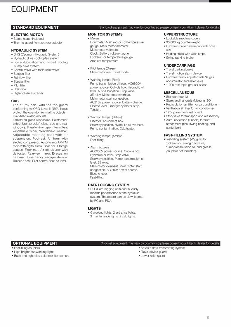
ELECTRIC MOTOR• Space heater included• Thermo-guard (temperature detector)
HYDRAULIC SYSTEM• OHS (Optimum Hydraulic System)• Hydraulic drive cooling-fan system• Forced-lubrication and forced cooling
pump drive system• Control valve with main relief valve• Suction filter• Full-flow filter• Bypass filter• Pilot filter • Drain filter• High-pressure strainer
CABThe sturdy cab, with the top guard conforming to OPG Level ll (ISO), helps protect the operator from falling objects.Fluid-filled elastic mounts.Laminated glass windshield. Reinforced/tinted (bronze color) glass side and rear windows. Parallel-link-type intermittent windshield wiper. Windshield washer. Ad justab le rec l in ing seat wi th a i r suspension. Footrest. Air horn with electric compressor. Auto-tuning AM-FM radio with digital clock. Seat belt. Storage spaces. Floor mat. Air conditioner with defroster. Rearview mirror. Evacuation hammer. Emergency escape device. Trainer's seat. Pilot control shut-off lever.
MONITOR SYSTEMS • Meters:
Hourmeter. Main motor coil temperature gauge. Main motor ammeter. Main motor voltmeter. Clock. Battery voltage gauge.Hydraulic oil temperature gauge.Ambient temperature.
• Pilot lamps (Green): Main motor run. Travel mode.
• Warning lamps: (Red): Pump transmission oil level. AC6600V power source. Cubicle box. Hydraulic oil level. Auto-lubrication. Stop valve. 3E relay. Main motor overheat. Main motor start congestion. AC210V power source. Battery charge. Electric lever. Emergency motor stop. Tension.
• Warning lamps: (Yellow): Electrical equipment box. Stairway position. Hydraulic oil overheat. Pump contamination. Cab.heater.
• Warning lamps: (Amber): Fast-filling.
• Alarm buzzers: AC6600V power source. Cubicle box. Hydraulic oil level. Stop valve. Stairway position. Pump transmission oil level. 3E relay. Main motor overheat. Main motor start congestion. AC210V power source. Electric lever. Fast-filling.
DATA LOGGING SYSTEM• DLU(Data-logging unit) continuously
records performance of the hydraulic system. The record can be downloaded by PC and PDA.
LIGHTS• 6 working lights. 2 entrance lights.
3 maintenance lights. 2 cab lights.
UPPERSTRUCTURE• Lockable machine covers• 30 000 kg counterweight• Hydraulic drive grease gun with hose
reel• Folding stairs with wide steps• Swing parking brake
UNDERCARRIAGE• Travel parking brake• Travel motion alarm device• Hydraulic track adjuster with N2 gas
accumulator and relief valve• 1 000 mm triple grouser shoes
MISCELLANEOUS• Standard tool kit• Stairs and handrails (Meeting ISO)• Recirculation air filter for air conditioner• Ventilation air filter for air conditioner• 12 V power terminal board• Stop valve for transport and reassembly• Auto-lubrication (Lincoln) for front-
attachment pins, swing bearing, and center joint
FAST-FILLING SYSTEM•Fast-filling system (Wiggins) for hydraulic oil, swing device oil, pump transmission oil, and grease (couplers not included).
OPTIONAL EQUIPMENT Optional equipment may vary by country, so please consult your Hitachi dealer for details.
• Fast-filling couplers• High brightness working lights• Back and right side color monitor camera
• Satellite data transmitting system• Travel device guard• Lower roller guard
STANDARD EQUIPMENT Standard equipment may vary by country, so please consult your Hitachi dealer for details.
EQUIPMENT
10
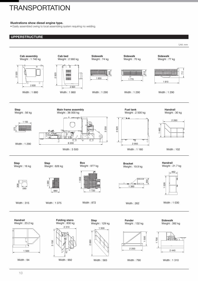
Illustrations show diesel engine type.• Easily assembled owing to local assembling system requiring no welding.
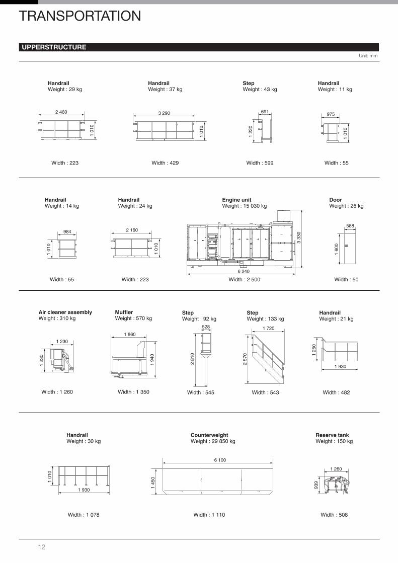
UPPERSTRUCTURE
Unit: mm
Cab assemblyWeight : 1 740 kg
Width : 1 880
2 830
2 52
0
Cab bedWeight : 2 560 kg
Width : 1 860
2 820
2 92
0SidewalkWeight : 74 kg
Width : 1 290
1 850
660
SidewalkWeight : 70 kg
Width : 1 290
1 770
612
SidewalkWeight : 77 kg
Width : 1 290
1 810
711
StepWeight : 56 kg
Width : 1 290
1 150
572
Main frame assemblyWeight : 36 000 kg
Width : 3 500
3 25
0
8 200
2 62
0
2 950
Fuel tankWeight : 2 500 kg
Width : 1 180
1 46
0
2 260
HandrailWeight : 30 kg
Width : 102
308
590
StepWeight : 16 kg
Width : 315
1 08
0
880
StepWeight : 626 kg
Width : 1 075
1 85
6
1 720
BoxWeight : 977 kg
Width : 872
3 15
0
2 310
Folding stairsWeight : 830 kg
Width : 992
2 66
0
1 500
StepWeight : 129 kg
Width : 583
1 50
0
2 200
FenderWeight : 132 kg
Width : 790
1 70
0
2 440
SidewalkWeight : 392 kg
Width : 1 310
TRANSPORTATION
350
1 360
BracketWeight : 19.9 kg
Width : 262
HandrailWeight : 21.7 kg
Width : 1 030
1 02
6
462
HandrailWeight : 23.2 kg
Width : 94
1 500
11
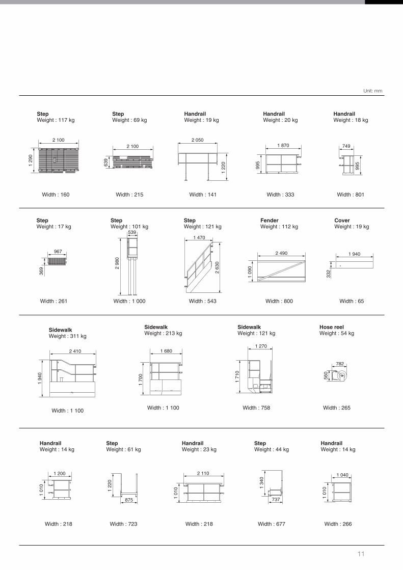
Unit: mm
1 29
0
2 100
StepWeight : 117 kg
Width : 160
639
2 100
StepWeight : 69 kg
Width : 215
1 22
0
2 050
HandrailWeight : 19 kg
Width : 141
995
1 870
HandrailWeight : 20 kg
Width : 333
995
749
HandrailWeight : 18 kg
Width : 801
369
967
StepWeight : 17 kg
Width : 261
2 98
0
539
StepWeight : 101 kg
Width : 1 000
2 63
0
1 470
StepWeight : 121 kg
Width : 543
1 70
0
1 680
SidewalkWeight : 213 kg
Width : 1 100
1 71
0
1 270
SidewalkWeight : 121 kg
Width : 758
560
782
Hose reelWeight : 54 kg
Width : 265
1 01
0
1 200
HandrailWeight : 14 kg
Width : 218
1 22
0
875
StepWeight : 61 kg
Width : 723
1 01
0
2 110
HandrailWeight : 23 kg
Width : 218
1 34
0
737
StepWeight : 44 kg
Width : 677
1 01
0
1 040
HandrailWeight : 14 kg
Width : 266
1 09
02 490
FenderWeight : 112 kg
Width : 800
332
1 940
CoverWeight : 19 kg
Width : 65
1 94
0
2 410
SidewalkWeight : 311 kg
Width : 1 100
12
UPPERSTRUCTUREUnit: mm
1 01
0
2 460
HandrailWeight : 29 kg
Width : 223
1 01
0
3 290
HandrailWeight : 37 kg
Width : 429
1 22
0
691
StepWeight : 43 kg
Width : 599
1 01
0
975
HandrailWeight : 11 kg
Width : 55
1 01
0
984
HandrailWeight : 14 kg
Width : 55
1 01
0
2 160
HandrailWeight : 24 kg
Width : 223
3 33
0
6 240
Engine unitWeight : 15 030 kg
Width : 2 500
1 23
0
1 230
Air cleaner assemblyWeight : 310 kg
Width : 1 260
1 94
0
1 860
MufflerWeight : 570 kg
Width : 1 350
2 81
0
528
StepWeight : 92 kg
Width : 545
2 57
0
1 720
StepWeight : 133 kg
Width : 543
1 25
0
1 930
HandrailWeight : 21 kg
Width : 482
1 01
0
1 930
HandrailWeight : 30 kg
Width : 1 078
1 45
0
6 100
CounterweightWeight : 29 850 kg
Width : 1 110
939
1 260
Reserve tankWeight : 150 kg
Width : 508
1 60
0
588
DoorWeight : 26 kg
Width : 50
TRANSPORTATION
13
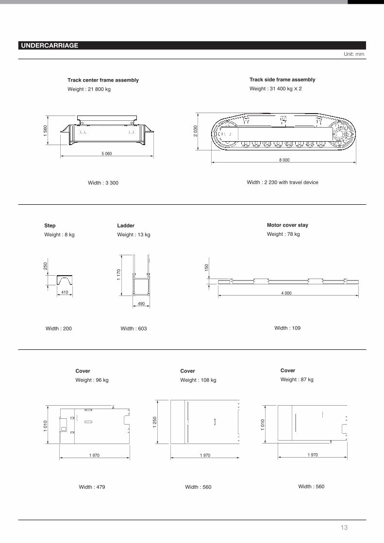
UNDERCARRIAGEUnit: mm
5 060
1 56
0
Track center frame assembly
Weight : 21 800 kg
Width : 3 300
8 000
2 03
0
Track side frame assemblyWeight : 31 400 kg X 2
Width : 2 230 with travel device
410
250
Step
Weight : 8 kg
Width : 200
Cover
Weight : 96 kg
Width : 479
1 970
1 01
0
Cover
Weight : 108 kg
Width : 560
1 970
1 25
0
Ladder
Weight : 13 kg
Width : 603
490
1 17
0
4 000
150
Motor cover stayWeight : 78 kg
Width : 109
CoverWeight : 87 kg
Width : 560
1 970
1 01
0
14
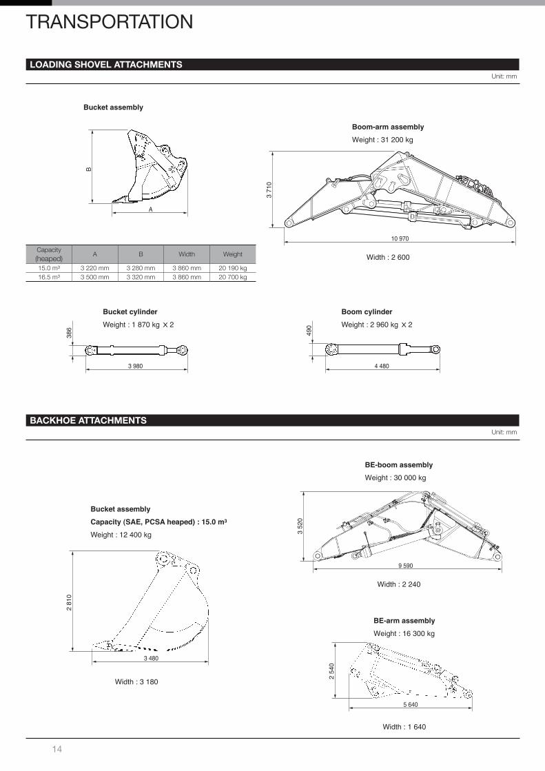
LOADING SHOVEL ATTACHMENTSUnit: mm
3 980
386
Bucket cylinderWeight : 1 870 kg X 2
4 480
490
Boom cylinderWeight : 2 960 kg X 2
Bucket assembly
A
B
Boom-arm assembly
Weight : 31 200 kg
Width : 2 600
10 970
3 71
0
Capacity (heaped)
A B Width Weight
15.0 m³ 3 220 mm 3 280 mm 3 860 mm 20 190 kg16.5 m³ 3 500 mm 3 320 mm 3 860 mm 20 700 kg
Bucket assemblyCapacity (SAE, PCSA heaped) : 15.0 m3
Weight : 12 400 kg
Width : 3 180
3 480
2 81
0
BE-boom assembly
Weight : 30 000 kg
Width : 2 240
9 590
3 52
0
BE-arm assembly
Weight : 16 300 kg
Width : 1 640
5 640
2 54
0
BACKHOE ATTACHMENTSUnit: mm
TRANSPORTATION
15
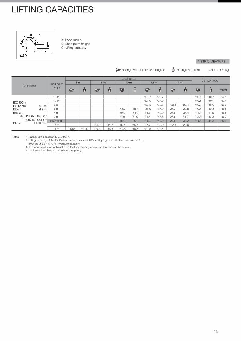
METRIC MEASURE
Rating over-side or 360 degree Rating over-front Unit: 1 000 kg
ConditionsLoad point
height
Load radiusAt max. reach
6 m 8 m 10 m 12 m 14 m
meter
EX2500-6
BE-boom 9.0 mBE-arm 4.2 m Bucket
SAE, PCSA : 15.0 m³CECE : 13.2 m³
Shoes 1 000 mm
12 m *20.7 *20.7 *10.7 *10.7 14.810 m *27.0 *27.0 *10.1 *10.1 15.78 m *30.5 *30.5 *23.4 *23.4 *10.0 *10.0 16.36 m *45.7 *45.7 *37.9 *37.9 28.3 *29.5 *10.3 *10.3 16.54 m 50.9 *54.0 36.7 *42.0 26.8 *34.4 *11.0 *11.0 16.42 m 47.6 *51.9 34.5 *43.6 25.6 34.2 *12.3 *12.3 16.0
0 (Ground) 45.9 *49.1 33.2 *42.9 24.8 *33.2 *14.3 *14.3 15.2-2 m *34.2 *34.2 45.5 *50.5 32.7 *39.0 *22.6 *22.6-4 m *40.8 *40.8 *36.8 *36.8 *40.5 *40.5 *29.5 *29.5
Notes: 1.Ratings are based on SAE J1097. 2.Lifting capacity of the EX Series does not exceed 75% of tipping load with the machine on firm, level ground or 87% full hydraulic capacity. 3.The load point is a hook (not standard equipment) loaded on the back of the bucket. 4.*Indicates load limited by hydraulic capacity.
A: Load radiusB: Load point heightC: Lifting capacity
LIFTING CAPACITIES

09.08 (KA/KA,FT3)
Printed in Japan
KS-EN051RHitachi Construction Machinery Co., Ltd.www.hitachi-c-m.com
These specifications are subject to change without notice.Illustrations and photos show the standard models, and may or may not include optional equipment, accessories, and all standard equipment with some differences in color and features.Before use, read and understand the Operator’s Manual for proper operation.