Embed Size (px)
Citation preview
(English) DM-BR0005-12
XTRBR-M9000BR-M9020BR-M987
BL-M9000BL-M9020BL-M988-BBL-M987
SAINTBR-M820
BL-M820BL-M820-B
DEORE XTBR-M8000BR-M785
BL-M8000BL-M785-B
SLXBR-M675
BL-M675BL-M675-B
ZEEBR-M640
BL-M640BL-M640-B
DEOREBR-M615
BL-M615
ALIVIOBR-M4050
SHIMANOBR-M447BR-M395
BL-M506BL-M425BL-M396BL-M395
DEORE XT (Trekking)BL-T785-B
DEORE LX (Trekking)BR-T675
BL-T675BL-T675-B
DEORE (Trekking)BR-T615
BL-T615
Mount adapterSM-MA-F180P/P2
Dealer's Manual
ROAD MTB Trekking
City Touring/ Comfort Bike
URBAN SPORT E-BIKE
Hydraulic Disc Brake
2
CONTENTS
IMPORTANT NOTICE ............................................................................................. 3
TO ENSURE SAFETY ............................................................................................... 4
LIST OF TOOLS TO BE USED ................................................................................ 11
INSTALLATION ..................................................................................................... 13Disc brake mount adapter (for 180mm disc brake rotors) ......................................................................13
Disc brake rotor adapter ............................................................................................................................14
Brake hose ..................................................................................................................................................17
MAINTENANCE .................................................................................................... 20Adding Shimano genuine mineral oil and bleeding air ..........................................................................20
Replacing the brake hose ..........................................................................................................................26
Replacing the brake pads ..........................................................................................................................33
Designated parts for magnesium products ..............................................................................................35
IMPORTANT NOTICE
3
IMPORTANT NOTICE
• This dealer’s manual is intended primarily for use by professional bicycle mechanics. Users who are not professionally trained for bicycle assembly should not attempt to install the components themselves using the dealer’s manuals. If any part of the information on the manual is unclear to you, do not proceed with the installation. Instead, contact your place of purchase or a local bicycle dealer for their assistance.
• Make sure to read all instruction manuals included with the product.
• Do not disassemble or modify the product other than as stated in the information contained in this dealer’s manual.
• All dealer’s manuals and instruction manuals can be viewed on-line on our website (http://si.shimano.com).
• Please observe the appropriate rules and regulations of the country, state or region in which you conduct your business as a dealer.
For safety, be sure to read this dealer’s manual thoroughly before use, and follow it for correct use.
The following instructions must be observed at all times in order to prevent personal injury and physical damage to equipment and surroundings.The instructions are classified according to the degree of danger or damage which may occur if the product is used incorrectly.
DANGER
Failure to follow the instructions will result in death or serious injury.
WARNING
Failure to follow the instructions could result in death or serious injury.
CAUTION
Failure to follow the instructions could cause personal injury or physical damage to equipment and surroundings.
TO ENSURE SAFETY
4
TO ENSURE SAFETY
WARNING
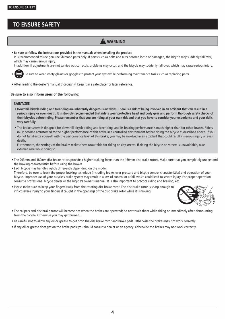
• Be sure to follow the instructions provided in the manuals when installing the product.It is recommended to use genuine Shimano parts only. If parts such as bolts and nuts become loose or damaged, the bicycle may suddenly fall over, which may cause serious injury.In addition, if adjustments are not carried out correctly, problems may occur, and the bicycle may suddenly fall over, which may cause serious injury.
• Be sure to wear safety glasses or goggles to protect your eyes while performing maintenance tasks such as replacing parts.
• After reading the dealer's manual thoroughly, keep it in a safe place for later reference.
Be sure to also inform users of the following:
SAINT/ZEE • Downhill bicycle riding and freeriding are inherently dangerous activities. There is a risk of being involved in an accident that can result in a serious injury or even death. It is strongly recommended that riders wear protective head and body gear and perform thorough safety checks of their bicycles before riding. Please remember that you are riding at your own risk and that you have to consider your experience and your skills very carefully.
• The brake system is designed for downhill bicycle riding and freeriding, and its braking performance is much higher than for other brakes. Riders must become accustomed to the higher performance of this brake in a controlled environment before riding the bicycle as described above. If you do not familiarize yourself with the performance level of this brake, you may be involved in an accident that could result in serious injury or even death. Furthermore, the settings of the brakes makes them unsuitable for riding on city streets. If riding the bicycle on streets is unavoidable, take extreme care while doing so.
• The 203mm and 180mm disc brake rotors provide a higher braking force than the 160mm disc brake rotors. Make sure that you completely understand the braking characteristics before using the brakes. • Each bicycle may handle slightly differently depending on the model. Therefore, be sure to learn the proper braking technique (including brake lever pressure and bicycle control characteristics) and operation of your bicycle. Improper use of your bicycle's brake system may result in a loss of control or a fall, which could lead to severe injury. For proper operation, consult a professional bicycle dealer or the bicycle's owner's manual. It is also important to practice riding and braking, etc.
• Please make sure to keep your fingers away from the rotating disc brake rotor. The disc brake rotor is sharp enough to inflict severe injury to your fingers if caught in the openings of the disc brake rotor while it is moving.
• The calipers and disc brake rotor will become hot when the brakes are operated; do not touch them while riding or immediately after dismounting from the bicycle. Otherwise you may get burned.
• Be careful not to allow any oil or grease to get onto the disc brake rotor and brake pads. Otherwise the brakes may not work correctly.
• If any oil or grease does get on the brake pads, you should consult a dealer or an agency. Otherwise the brakes may not work correctly.
TO ENSURE SAFETY
5
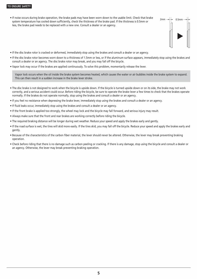
• If noise occurs during brake operation, the brake pads may have been worn down to the usable limit. Check that brake system temperature has cooled down sufficiently, check the thickness of the brake pad. If the thickness is 0.5mm or less, the brake pad needs to be replaced with a new one. Consult a dealer or an agency.
0.5mm2mm
• If the disc brake rotor is cracked or deformed, immediately stop using the brakes and consult a dealer or an agency.
• If the disc brake rotor becomes worn down to a thickness of 1.5mm or less, or if the aluminum surface appears, immediately stop using the brakes and consult a dealer or an agency. The disc brake rotor may break, and you may fall off the bicycle.
• Vapor lock may occur if the brakes are applied continuously. To solve this problem, momentarily release the lever.
Vapor lock occurs when the oil inside the brake system becomes heated, which causes the water or air bubbles inside the brake system to expand. This can then result in a sudden increase in the brake lever stroke.
• The disc brake is not designed to work when the bicycle is upside down. If the bicycle is turned upside down or on its side, the brake may not work correctly, and a serious accident could occur. Before riding the bicycle, be sure to operate the brake lever a few times to check that the brakes operate normally. If the brakes do not operate normally, stop using the brakes and consult a dealer or an agency.
• If you feel no resistance when depressing the brake lever, immediately stop using the brakes and consult a dealer or an agency.
• If fluid leaks occur, immediately stop using the brakes and consult a dealer or an agency.
• If the front brake is applied too strongly, the wheel may lock and the bicycle may fall forward, and serious injury may result.
• Always make sure that the front and rear brakes are working correctly before riding the bicycle.
• The required braking distance will be longer during wet weather. Reduce your speed and apply the brakes early and gently.
• If the road surface is wet, the tires will skid more easily. If the tires skid, you may fall off the bicycle. Reduce your speed and apply the brakes early and gently.
• Because of the characteristics of the carbon fiber material, the lever should never be altered. Otherwise, the lever may break preventing braking operation.
• Check before riding that there is no damage such as carbon peeling or cracking. If there is any damage, stop using the bicycle and consult a dealer or an agency. Otherwise, the lever may break preventing braking operation.
TO ENSURE SAFETY
6
For Installation to the Bicycle, and Maintenance:
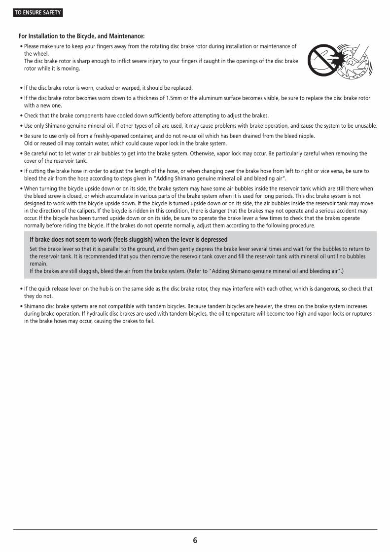
• Please make sure to keep your fingers away from the rotating disc brake rotor during installation or maintenance of the wheel. The disc brake rotor is sharp enough to inflict severe injury to your fingers if caught in the openings of the disc brake rotor while it is moving.
• If the disc brake rotor is worn, cracked or warped, it should be replaced.
• If the disc brake rotor becomes worn down to a thickness of 1.5mm or the aluminum surface becomes visible, be sure to replace the disc brake rotor with a new one.
• Check that the brake components have cooled down sufficiently before attempting to adjust the brakes.
• Use only Shimano genuine mineral oil. If other types of oil are used, it may cause problems with brake operation, and cause the system to be unusable.
• Be sure to use only oil from a freshly-opened container, and do not re-use oil which has been drained from the bleed nipple. Old or reused oil may contain water, which could cause vapor lock in the brake system.
• Be careful not to let water or air bubbles to get into the brake system. Otherwise, vapor lock may occur. Be particularly careful when removing the cover of the reservoir tank.
• If cutting the brake hose in order to adjust the length of the hose, or when changing over the brake hose from left to right or vice versa, be sure to bleed the air from the hose according to steps given in “Adding Shimano genuine mineral oil and bleeding air”.
• When turning the bicycle upside down or on its side, the brake system may have some air bubbles inside the reservoir tank which are still there when the bleed screw is closed, or which accumulate in various parts of the brake system when it is used for long periods. This disc brake system is not designed to work with the bicycle upside down. If the bicycle is turned upside down or on its side, the air bubbles inside the reservoir tank may move in the direction of the calipers. If the bicycle is ridden in this condition, there is danger that the brakes may not operate and a serious accident may occur. If the bicycle has been turned upside down or on its side, be sure to operate the brake lever a few times to check that the brakes operate normally before riding the bicycle. If the brakes do not operate normally, adjust them according to the following procedure.
If brake does not seem to work (feels sluggish) when the lever is depressed Set the brake lever so that it is parallel to the ground, and then gently depress the brake lever several times and wait for the bubbles to return to the reservoir tank. It is recommended that you then remove the reservoir tank cover and fill the reservoir tank with mineral oil until no bubbles remain. If the brakes are still sluggish, bleed the air from the brake system. (Refer to "Adding Shimano genuine mineral oil and bleeding air".)
• If the quick release lever on the hub is on the same side as the disc brake rotor, they may interfere with each other, which is dangerous, so check that they do not.
• Shimano disc brake systems are not compatible with tandem bicycles. Because tandem bicycles are heavier, the stress on the brake system increases during brake operation. If hydraulic disc brakes are used with tandem bicycles, the oil temperature will become too high and vapor locks or ruptures in the brake hoses may occur, causing the brakes to fail.
TO ENSURE SAFETY
7
�SM-RTAD05 Disc brake rotor adapter
• Disc brake rotors with diameters of up to Ø203mm can be installed. If disc brake rotors with a larger diameter than this are installed, the braking force may damage the main unit.
�Brake hose
• After installing the brake hose to the brake unit, adding Shimano genuine mineral oil and bleeding air bubbles, depress the lever again several times to check that the brakes are operating normally and there are no fluid leaks from the hose or the system.
• The connector insert is for this brake hose only. Use an appropriate connector insert according to the following table. Use of a connector insert incompatible with the brake hose may cause fluid leaks.
Model No. Length ColorSM-BH90 11.2mm Silver
SM-BH59/80 13.2mm Gold YM-BH81 13.2mm Silver
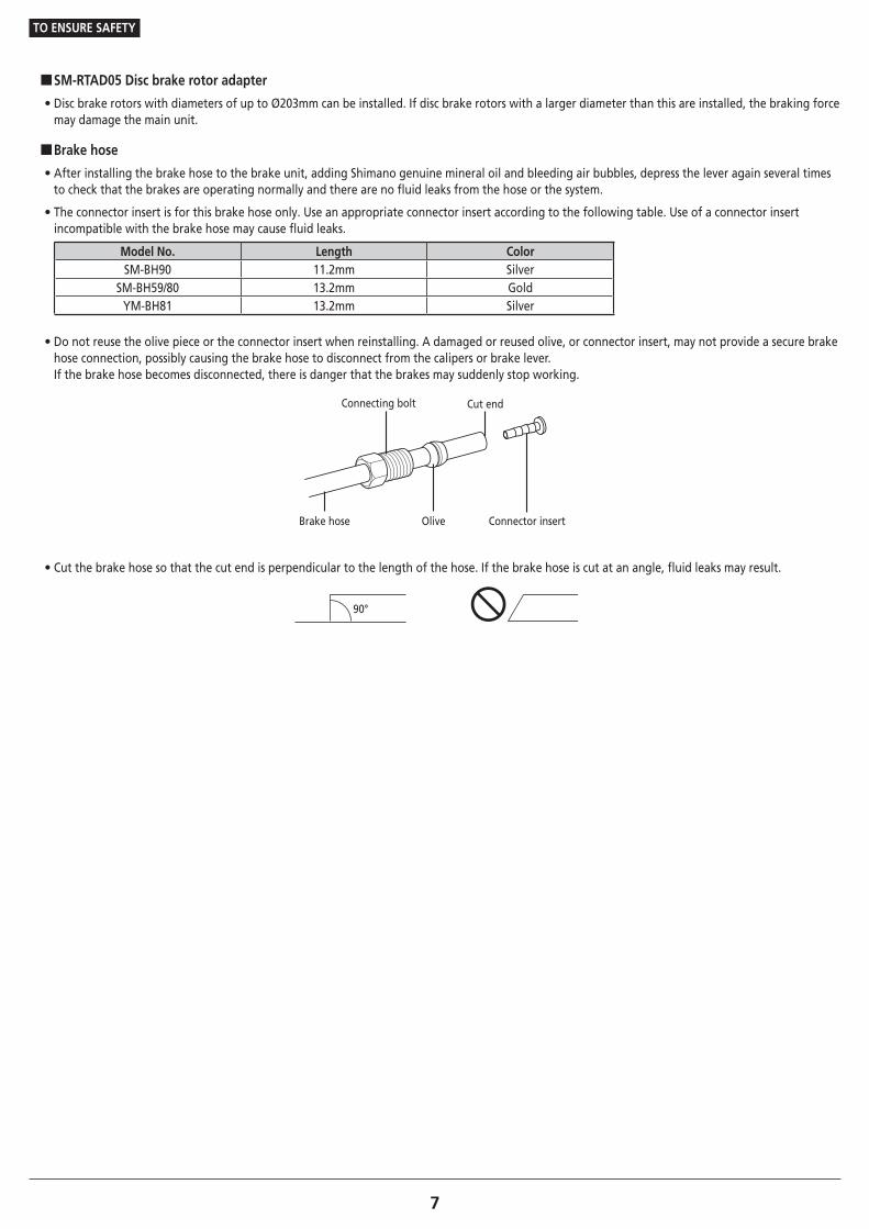
• Do not reuse the olive piece or the connector insert when reinstalling. A damaged or reused olive, or connector insert, may not provide a secure brake hose connection, possibly causing the brake hose to disconnect from the calipers or brake lever. If the brake hose becomes disconnected, there is danger that the brakes may suddenly stop working.
Brake hose Olive
Connecting bolt Cut end
Connector insert
• Cut the brake hose so that the cut end is perpendicular to the length of the hose. If the brake hose is cut at an angle, fluid leaks may result.
90°
TO ENSURE SAFETY
8
CAUTION
Be sure to also inform users of the following:
�Cautions on Shimano genuine mineral oil • Contact with eyes may result in irritation. In the event of contact with eye, wash with water and seek medical attention immediately.
• Contact with skin may cause a rash and discomfort. In the event of contact with skin, wash well with soap and water.
• Inhalation of Shimano genuine mineral oil mist or vapors may cause nausea. Cover nose and mouth with a respirator type mask and use in a well ventilated area. If Shimano genuine mineral oil mist or vapor is inhaled, cover up with a blanket and go immediately to an area with fresh air. Stay warm and calm, and seek professional medical advice.
�Burn-in period
• Disc brakes have a burn-in period, and the braking force will gradually increase as the burn-in period progresses. Make sure that you are aware of any such increases in braking force when using the brakes during the burn-in period. The same thing will happen when the brake pads or disc brake rotor are replaced.
For Installation to the Bicycle, and Maintenance:
• When using the Shimano original tool (TL-FC36) to remove and install the disc brake rotor fixing ring, be careful not to touch the outside of the disc brake rotor with your hands. Wear gloves to protect your hands from getting cut.
�Handling Shimano genuine mineral oil
• Contact with eyes may result in irritation. Use safety glasses when handling, and avoid contact with eyes. In the event of contact with eye, wash with water and seek medical attention immediately.
• Contact with skin may cause a rash and discomfort. Use gloves when handling. In the event of contact with skin, wash well with soap and water.
• Do not drink. May cause vomiting or diarrhea.
• Keep out of reach of children.
• Do not cut, let near heat, weld or pressurize the oil container, as this may cause explosion or fire.
• Disposal of Used Oil: Follow local county and/or state codes for disposal. Use caution when preparing the oil for disposal.
• Directions: Keep the container sealed to prevent foreign objects and moisture from getting inside, and store it in a cool, dark area away from direct sunlight or heat. Keep from heat or flame, Petroleum Class III, Danger level III
�When cleaning with a compressor
• If disassembling the caliper body to clean the internal parts using a compressor, note that moisture from the compressed air may remain on the caliper components. Let the caliper components dry sufficiently before reassembling the calipers.
�Brake hose
• When cutting the brake hose, handle the knife carefully so as not to cause injury.
• Be careful to avoid injury from the olive.
TO ENSURE SAFETY
9
NOTE
Be sure to also inform users of the following:
• When the bicycle wheel has been removed, it is recommended that pad spacers are installed. Do not depress the brake lever while the wheel is removed. If the brake lever is depressed without the pad spacers installed, the pistons will protrude further than normal. If that happens, consult a dealer.
• Use soapy water and a dry cloth when cleaning and carrying out maintenance of the brake system. Do not use commercially available brake cleansers or silencing agents. Such substances can cause damage to parts such as seals.
• In the case of carbon levers, wash them with a soft cloth using a neutral detergent. Otherwise, the material may break down and be damaged.
• Avoid leaving the carbon levers in areas of high temperature. Also keep them well away from fire.
• Products are not guaranteed against natural wear and deterioration from normal use and aging.
• For maximum performance we highly recommend Shimano lubricants and maintenance products.
�SAINT/ZEE
• This product is not warranted against damage resulting from improper use, such as jumping while riding or if the bicycle falls over, except if such malfunctions are caused by manufacturing methods.
For Installation to the Bicycle, and Maintenance:
• The 203mm and 180mm disc brake rotors have a larger diameter than the 160mm disc brake rotor for cross-country bicycles, and so the flexing of these disc brake rotors is greater. As a result, they will interfere with the brake pads.
• If the brake caliper mounting boss and the fork end are not parallel, the disc brake rotor and caliper may touch.
• When the bicycle wheel has been removed, it is recommended that pad spacers are installed. The pad spacers will prevent the piston from coming out if the brake lever is depressed while the wheel is removed.
• If the brake lever is depressed without the pad spacers installed, the pistons will protrude further than is normal. Use a flat-shaped tool to push back the brake pads, while being careful not to damage the surfaces of the brake pads. (If the brake pads are not installed, use a flat-shaped tool to push the pistons straight back in, while being careful not to damage them.) If it is difficult to push the brake pads or pistons back, remove the bleed screws and then try again. (Note that some oil may overflow from the reservoir tank at this time.)
• Use isopropyl alcohol, soapy water or a dry cloth when cleaning and carrying out maintenance of the brake system. Do not use commercially available brake cleansers or silencing agents. Such substances can cause damage to parts such as seals.
• Do not remove the pistons when disassembling the calipers.
• If the disc brake rotor is worn, cracked or warped, it should be replaced.
• The caliper of BR-M9000/BR-M987 and the master cylinder of BL-M9000/BL-M987 are made of magnesium. Corrosion starts when these components come into contact with parts made of other types of metals, such as iron bolts. In the contact area, water residue, sweat, rain and other moisture particles may create a potential reaction. This forms an electrochemical cell, resulting in an electrochemical reaction. To prevent this problem, each part is treated with a special-purpose surface treatment. Use appropriate parts to prevent the progression of rusting. For more details, refer to "Designated parts for magnesium products" in "MAINTENANCE".
�SM-RTAD05 Disc brake rotor adapter
• When using this disc brake rotor adapter to install disc brake rotors, the structure of the adapter means that there will be more play than normal in the disc brake rotor. Because of this, the disc brake rotor may interfere with the brake pads. Furthermore, it may also interfere with the calipers in the radial direction (upward).
• This product cannot be used with the 6-bolt disc brake rotor that is installed with an aluminum adapter (SM-RT86/RT76).
The actual product may differ from the illustration because this manual is intended mainly to explain the procedures for using the product.
LIST OF TOOLS TO BE USED
LIST OF TOOLS TO BE USED
11
LIST OF TOOLS TO BE USED
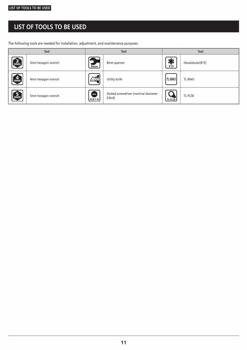
The following tools are needed for installation, adjustment, and maintenance purposes.
Tool Tool Tool
3mm hexagon wrench 8mm spanner Hexalobular[#15]
4mm hexagon wrench Utility knife TL-BH61
5mm hexagon wrench Slotted screwdriver (nominal diameter: 0.8×4)
TL-FC36

INSTALLATION
INSTALLATION
Disc brake mount adapter (for 180mm disc brake rotors)
13
INSTALLATION
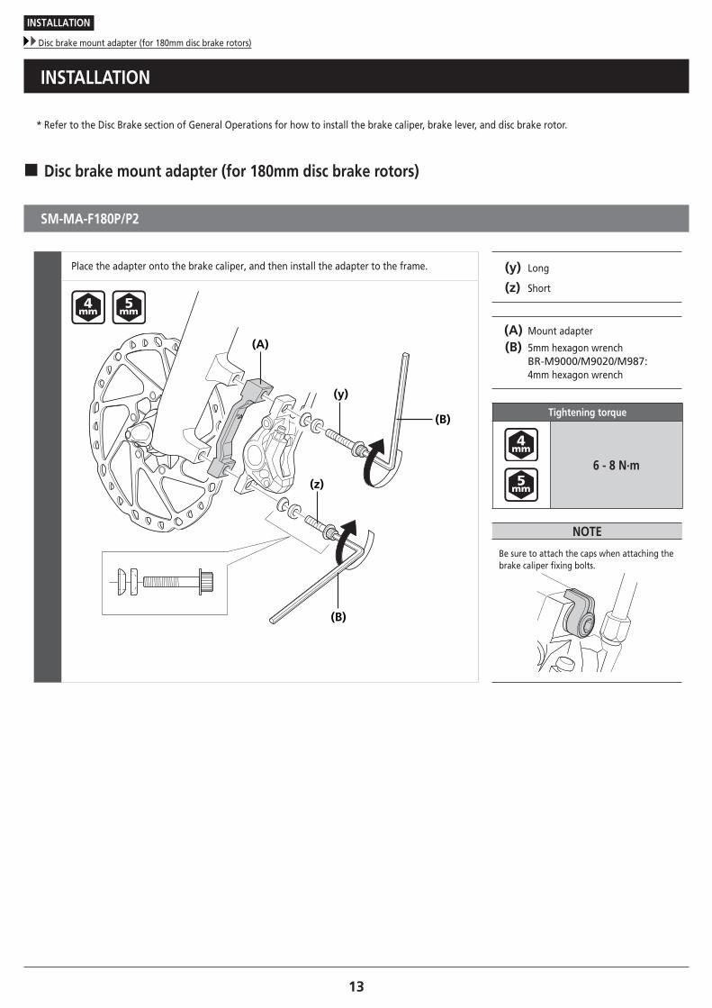
* Refer to the Disc Brake section of General Operations for how to install the brake caliper, brake lever, and disc brake rotor.
� Disc brake mount adapter (for 180mm disc brake rotors)
SM-MA-F180P/P2
Place the adapter onto the brake caliper, and then install the adapter to the frame. (y) Long
(z) Short
(A) Mount adapter
(B) 5mm hexagon wrench BR-M9000/M9020/M987: 4mm hexagon wrench
Tightening torque
6 - 8 N·m
NOTE
Be sure to attach the caps when attaching the brake caliper fixing bolts.
(y)
(z)
(A)
(B)
(B)
INSTALLATION
Disc brake rotor adapter
14To be continued on next page
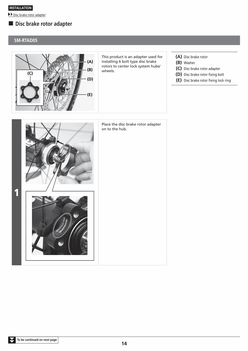
� Disc brake rotor adapter
SM-RTAD05
(C)(D)
(E)
(A)
(D)
(E)
(A)
(B)(B)
This product is an adapter used for installing 6 bolt type disc brake rotors to center lock system hubs/wheels.
(A) Disc brake rotor
(B) Washer
(C) Disc brake rotor adapter
(D) Disc brake rotor fixing bolt
(E) Disc brake rotor fixing lock ring
1
Place the disc brake rotor adapter on to the hub.
INSTALLATION
Disc brake rotor adapter
15To be continued on next page
2
(A)(A)
(B)(B)(z)(z)
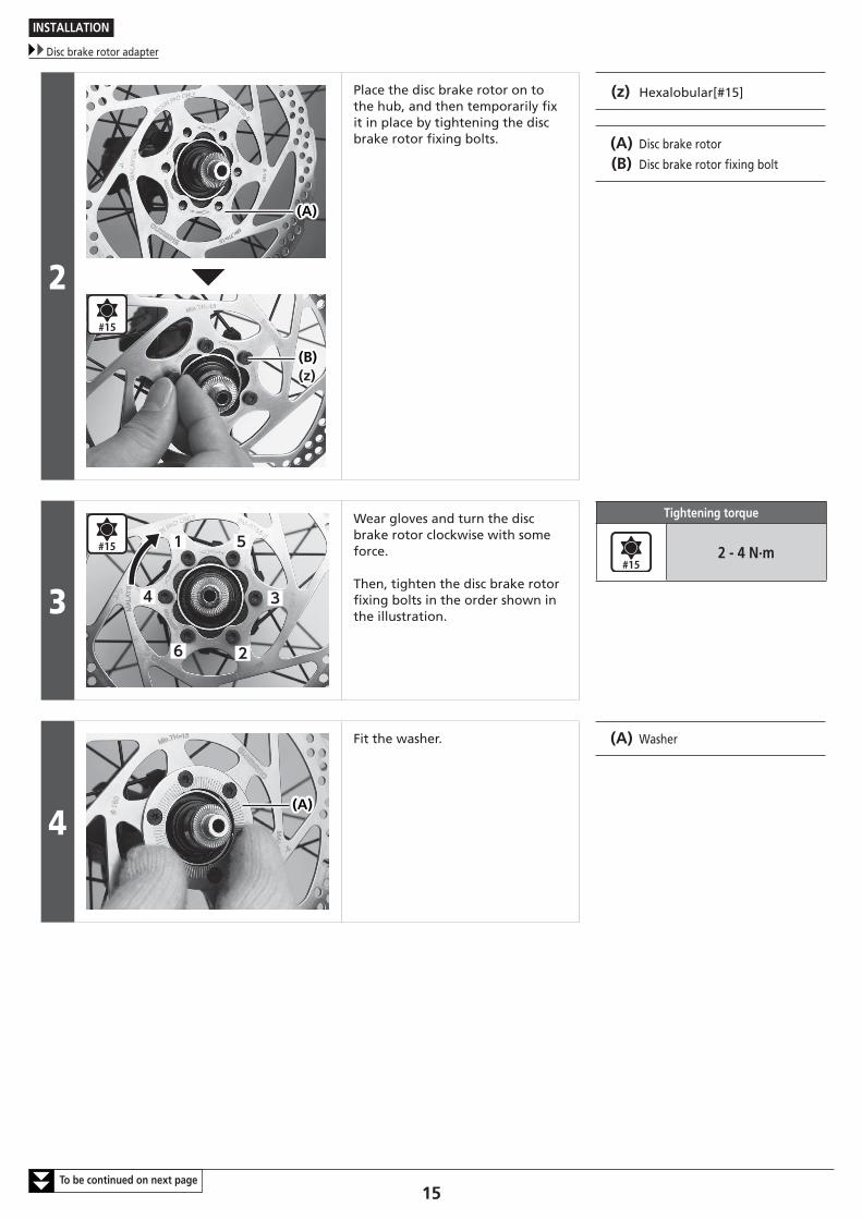
Place the disc brake rotor on to the hub, and then temporarily fix it in place by tightening the disc brake rotor fixing bolts.
(z) Hexalobular[#15]
(A) Disc brake rotor
(B) Disc brake rotor fixing bolt
3
1
2
34
5
6
Wear gloves and turn the disc brake rotor clockwise with some force.
Then, tighten the disc brake rotor fixing bolts in the order shown in the illustration.
Tightening torque
2 - 4 N·m
4(A)(A)
Fit the washer. (A) Washer
INSTALLATION
Disc brake rotor adapter
16
5
(A)(A)
(B)(B)
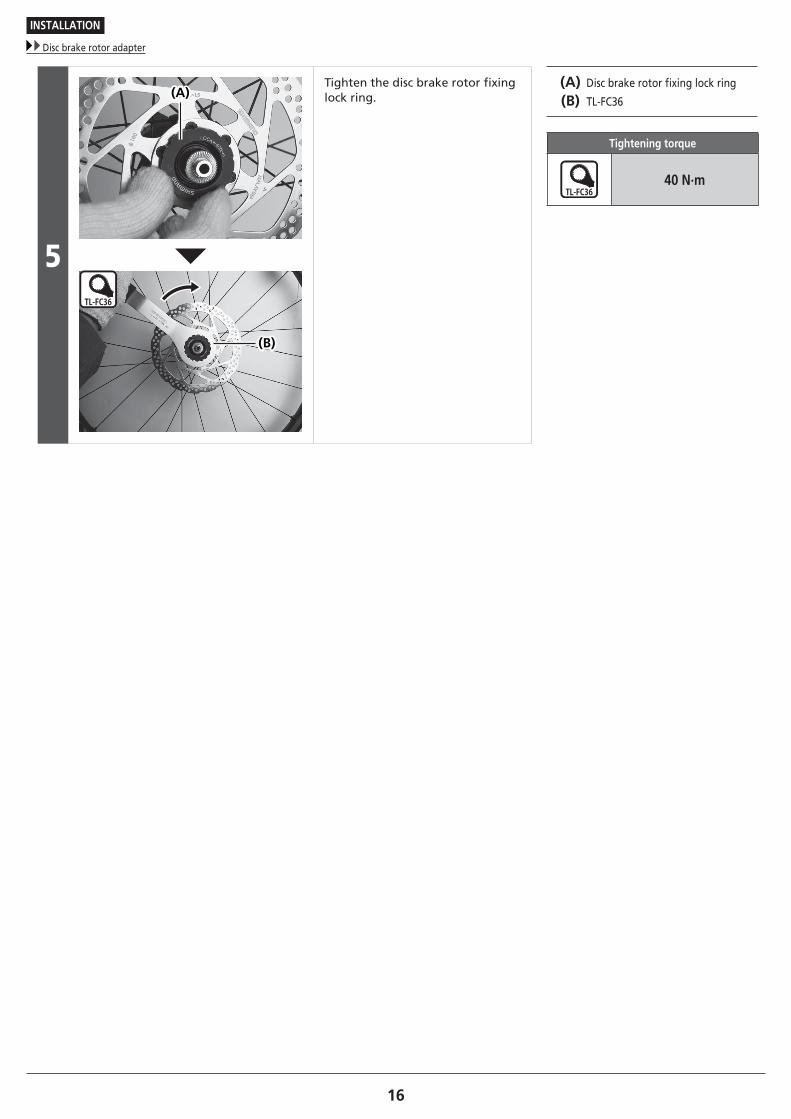
Tighten the disc brake rotor fixing lock ring.
(A) Disc brake rotor fixing lock ring
(B) TL-FC36
Tightening torque
40 N·m
INSTALLATION
Brake hose
17
� Brake hose
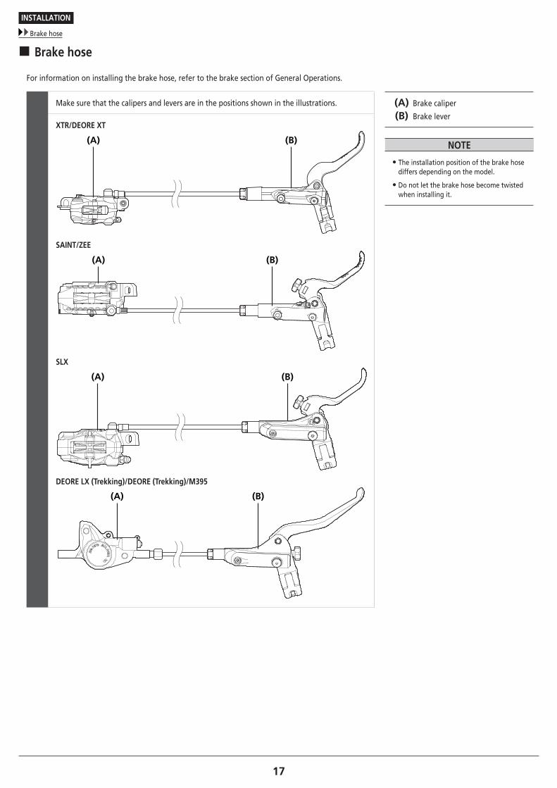
For information on installing the brake hose, refer to the brake section of General Operations.
Make sure that the calipers and levers are in the positions shown in the illustrations. (A) Brake caliper
(B) Brake lever
NOTE
• The installation position of the brake hose differs depending on the model.
• Do not let the brake hose become twisted when installing it.
XTR/DEORE XT
(B)(A)
SAINT/ZEE
(B)(A)
SLX
(B)(A)
DEORE LX (Trekking)/DEORE (Trekking)/M395
(B)(A)
INSTALLATION
Brake hose
18
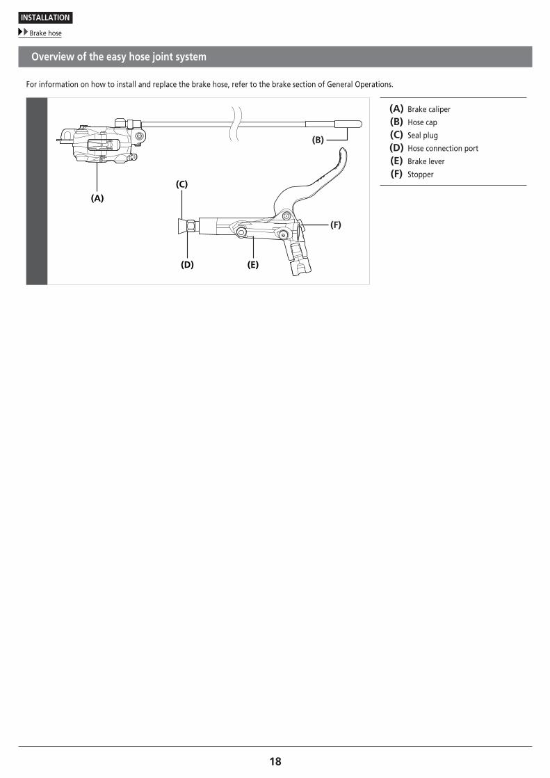
Overview of the easy hose joint system
For information on how to install and replace the brake hose, refer to the brake section of General Operations.
(A)
(D) (E)
(C)
(F)
(B)
(A) Brake caliper
(B) Hose cap
(C) Seal plug
(D) Hose connection port
(E) Brake lever
(F) Stopper

MAINTENANCE
MAINTENANCE
Adding Shimano genuine mineral oil and bleeding air
20To be continued on next page
MAINTENANCE
This section describes specification differences between products that are not included in the disc brake section of General Operations.
� Adding Shimano genuine mineral oil and bleeding air
BR-M447/BR-M4050/BR-M395
When removing air from the brake caliper, a funnel is needed.
TECH TIPS
Shimano genuine mineral oil replacement It is recommended to replace the oil inside the reservoir tank if it becomes severely discolored.Attach a tube with a bag to the bleed nipple, and then open the bleed nipple to drain out the oil. The brake lever can be operated at this time to help the oil drain out. After this, add oil while referring to the section "Adding Shimano genuine mineral oil and bleeding air".Use only Shimano genuine mineral oil.Dispose of the waste oil according to proper country and/or state disposal regulations.
1
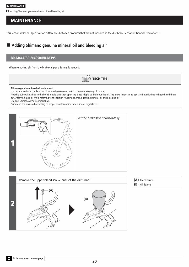
Set the brake lever horizontally.
2
Remove the upper bleed screw, and set the oil funnel. (A) Bleed screw
(B) Oil funnel
(A)
(B)
MAINTENANCE
Adding Shimano genuine mineral oil and bleeding air
21To be continued on next page
3
(z)(A)
(E)
(B)
(C)
(D)
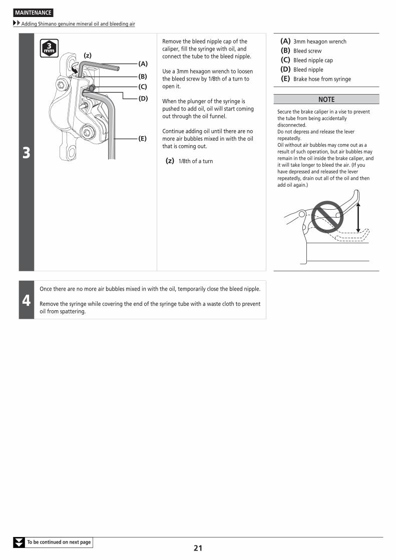
Remove the bleed nipple cap of the caliper, fill the syringe with oil, and connect the tube to the bleed nipple.
Use a 3mm hexagon wrench to loosen the bleed screw by 1/8th of a turn to open it.
When the plunger of the syringe is pushed to add oil, oil will start coming out through the oil funnel.
Continue adding oil until there are no more air bubbles mixed in with the oil that is coming out.
(z) 1/8th of a turn
(A) 3mm hexagon wrench
(B) Bleed screw
(C) Bleed nipple cap
(D) Bleed nipple
(E) Brake hose from syringe
NOTE
Secure the brake caliper in a vise to prevent the tube from being accidentally disconnected.Do not depress and release the lever repeatedly.Oil without air bubbles may come out as a result of such operation, but air bubbles may remain in the oil inside the brake caliper, and it will take longer to bleed the air. (If you have depressed and released the lever repeatedly, drain out all of the oil and then add oil again.)
4Once there are no more air bubbles mixed in with the oil, temporarily close the bleed nipple.
Remove the syringe while covering the end of the syringe tube with a waste cloth to prevent oil from spattering.
MAINTENANCE
Adding Shimano genuine mineral oil and bleeding air
22To be continued on next page
5
(A)
(B)
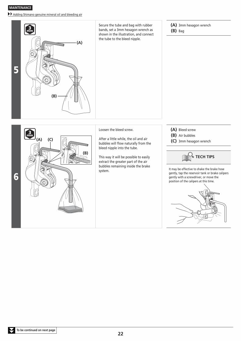
Secure the tube and bag with rubber bands, set a 3mm hexagon wrench as shown in the illustration, and connect the tube to the bleed nipple.
(A) 3mm hexagon wrench
(B) Bag
6
(B)
(C)(A)
Loosen the bleed screw.
After a little while, the oil and air bubbles will flow naturally from the bleed nipple into the tube.
This way it will be possible to easily extract the greater part of the air bubbles remaining inside the brake system.
(A) Bleed screw
(B) Air bubbles
(C) 3mm hexagon wrench
TECH TIPS
It may be effective to shake the brake hose gently, tap the reservoir tank or brake calipers gently with a screwdriver, or move the position of the calipers at this time.
MAINTENANCE
Adding Shimano genuine mineral oil and bleeding air
23To be continued on next page
7
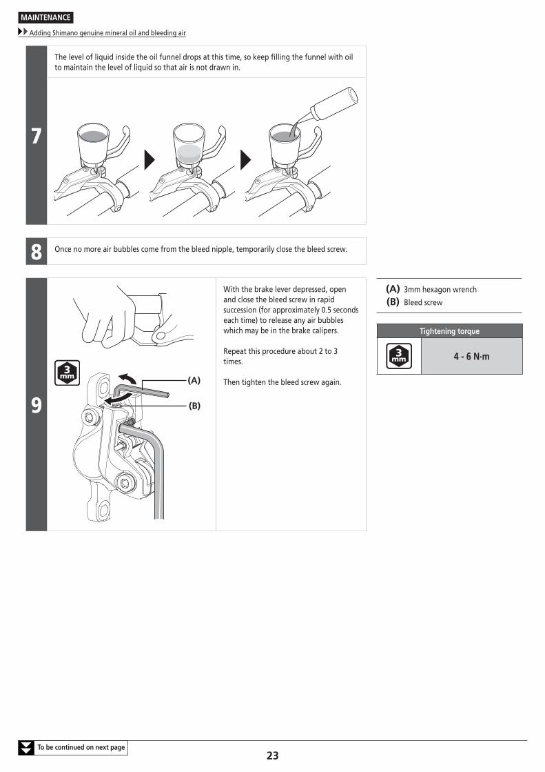
The level of liquid inside the oil funnel drops at this time, so keep filling the funnel with oil to maintain the level of liquid so that air is not drawn in.
8 Once no more air bubbles come from the bleed nipple, temporarily close the bleed screw.
9(A)
(B)
With the brake lever depressed, open and close the bleed screw in rapid succession (for approximately 0.5 seconds each time) to release any air bubbles which may be in the brake calipers.
Repeat this procedure about 2 to 3 times.
Then tighten the bleed screw again.
(A) 3mm hexagon wrench
(B) Bleed screw
Tightening torque
4 - 6 N·m
MAINTENANCE
Adding Shimano genuine mineral oil and bleeding air
24To be continued on next page
10
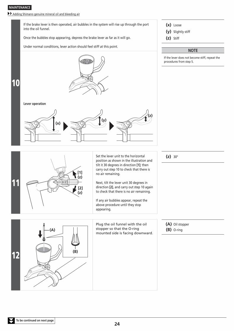
If the brake lever is then operated, air bubbles in the system will rise up through the port into the oil funnel.
Once the bubbles stop appearing, depress the brake lever as far as it will go.
Under normal conditions, lever action should feel stiff at this point.
(x) Loose
(y) Slightly stiff
(z) Stiff
NOTE
If the lever does not become stiff, repeat the procedures from step 5.
Lever operation
(x)(y)
(z)
11[1]
[2](z)
(z)
Set the lever unit to the horizontal position as shown in the illustration and tilt it 30 degrees in direction [1]; then carry out step 10 to check that there is no air remaining.
Next, tilt the lever unit 30 degrees in direction [2], and carry out step 10 again to check that there is no air remaining.
If any air bubbles appear, repeat the above procedure until they stop appearing.
(z) 30°
12
(A)
(B)
Plug the oil funnel with the oil stopper so that the O-ring mounted side is facing downward.
(A) Oil stopper
(B) O-ring
MAINTENANCE
Adding Shimano genuine mineral oil and bleeding air
25
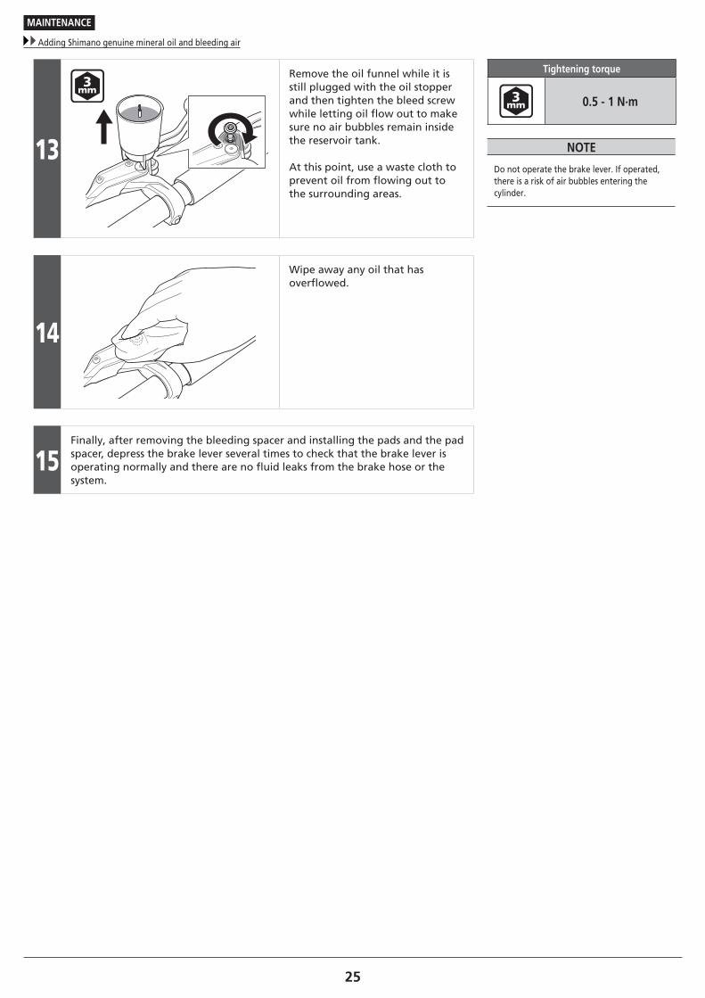
13
Remove the oil funnel while it is still plugged with the oil stopper and then tighten the bleed screw while letting oil flow out to make sure no air bubbles remain inside the reservoir tank.
At this point, use a waste cloth to prevent oil from flowing out to the surrounding areas.
Tightening torque
0.5 - 1 N·m
NOTE
Do not operate the brake lever. If operated, there is a risk of air bubbles entering the cylinder.
14
Wipe away any oil that has overflowed.
15Finally, after removing the bleeding spacer and installing the pads and the pad spacer, depress the brake lever several times to check that the brake lever is operating normally and there are no fluid leaks from the brake hose or the system.
MAINTENANCE
Replacing the brake hose
26To be continued on next page
� Replacing the brake hose
Brake lever side
NOTE
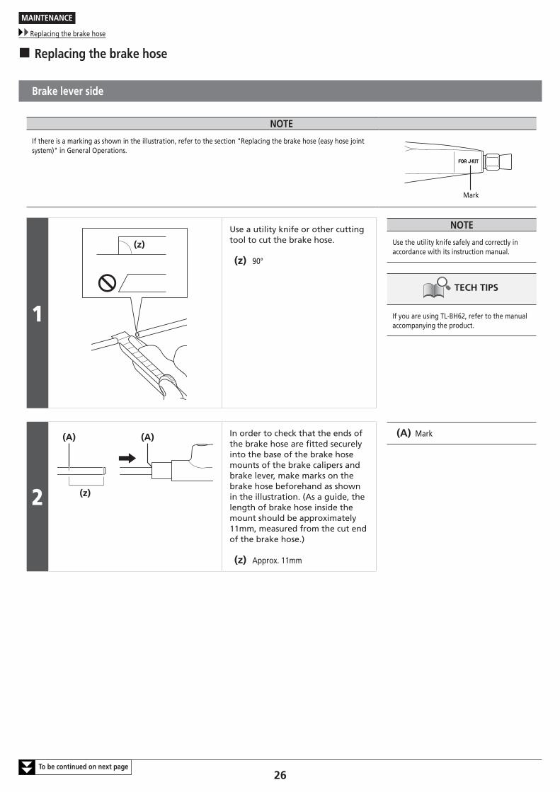
If there is a marking as shown in the illustration, refer to the section "Replacing the brake hose (easy hose joint system)" in General Operations.
Mark
1
(z)
Use a utility knife or other cutting tool to cut the brake hose.
(z) 90°
NOTE
Use the utility knife safely and correctly in accordance with its instruction manual.
TECH TIPS
If you are using TL-BH62, refer to the manual accompanying the product.
2 (z)
(A) (A) In order to check that the ends of the brake hose are fitted securely into the base of the brake hose mounts of the brake calipers and brake lever, make marks on the brake hose beforehand as shown in the illustration. (As a guide, the length of brake hose inside the mount should be approximately 11mm, measured from the cut end of the brake hose.)
(z) Approx. 11mm
(A) Mark
MAINTENANCE
Replacing the brake hose
27To be continued on next page
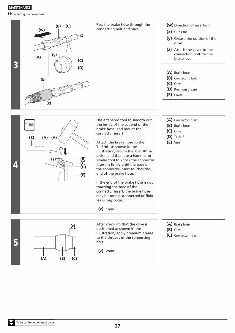
3(C)
(D)
(y)
(z)
(w)
(A)
(B) (C)
(E)
(x)
Pass the brake hose through the connecting bolt and olive.
(w) Direction of insertion
(x) Cut end
(y) Grease the outside of the olive.
(z) Attach the cover to the connecting bolt for the brake lever.
(A) Brake hose
(B) Connecting bolt
(C) Olive
(D) Premium grease
(E) Cover
4(z)
(B) (A)
(B)(C)(D)
(E)
(A)
Use a tapered tool to smooth out the inside of the cut end of the brake hose, and mount the connector insert.
Attach the brake hose to the TL-BH61 as shown in the illustration, secure the TL-BH61 in a vise, and then use a hammer or similar tool to knock the connector insert in firmly until the base of the connector insert touches the end of the brake hose.
If the end of the brake hose is not touching the base of the connector insert, the brake hose may become disconnected or fluid leaks may occur.
(z) 1mm
(A) Connector insert
(B) Brake hose
(C) Olive
(D) TL-BH61
(E) Vise
5
(z)
(A) (B) (C)
After checking that the olive is positioned as shown in the illustration, apply premium grease to the threads of the connecting bolt.
(z) 2mm
(A) Brake hose
(B) Olive
(C) Connector insert
MAINTENANCE
Replacing the brake hose
28
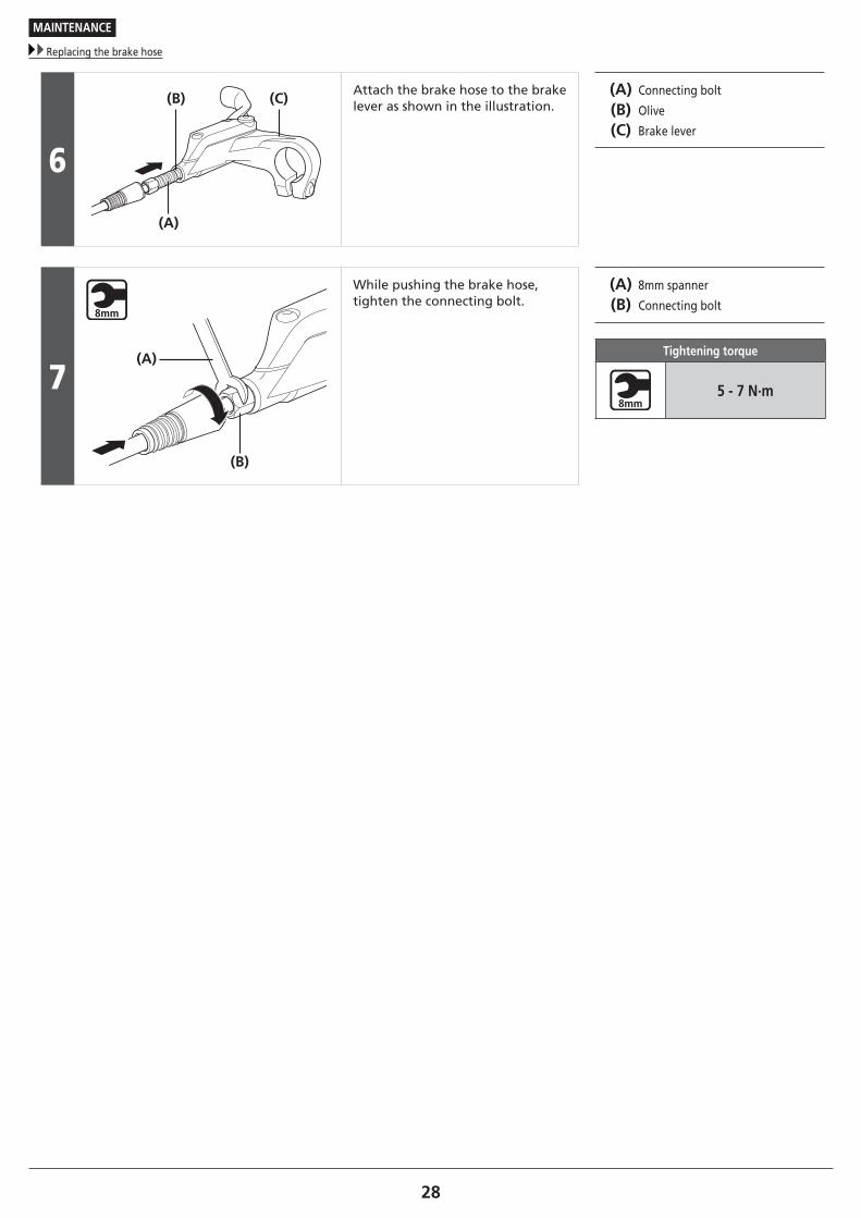
6
(C)(B)
(A)
Attach the brake hose to the brake lever as shown in the illustration.
(A) Connecting bolt
(B) Olive
(C) Brake lever
7(A)
(B)
While pushing the brake hose, tighten the connecting bolt.
(A) 8mm spanner
(B) Connecting bolt
Tightening torque
5 - 7 N·m
MAINTENANCE
Replacing the brake hose
29To be continued on next page
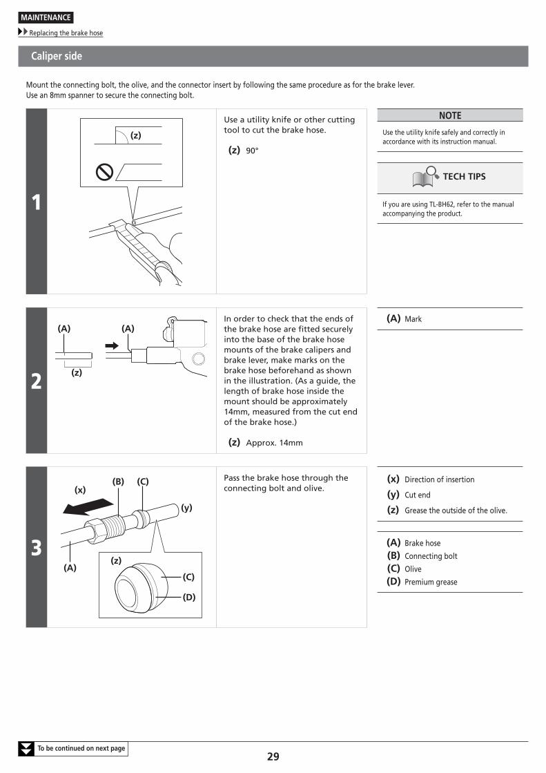
Caliper side
Mount the connecting bolt, the olive, and the connector insert by following the same procedure as for the brake lever.Use an 8mm spanner to secure the connecting bolt.
1
(z)
Use a utility knife or other cutting tool to cut the brake hose.
(z) 90°
NOTE
Use the utility knife safely and correctly in accordance with its instruction manual.
TECH TIPS
If you are using TL-BH62, refer to the manual accompanying the product.
2 (z)
(A) (A)In order to check that the ends of the brake hose are fitted securely into the base of the brake hose mounts of the brake calipers and brake lever, make marks on the brake hose beforehand as shown in the illustration. (As a guide, the length of brake hose inside the mount should be approximately 14mm, measured from the cut end of the brake hose.)
(z) Approx. 14mm
(A) Mark
3(z)
(x)
(A)
(B) (C)
(y)
(C)
(D)
Pass the brake hose through the connecting bolt and olive.
(x) Direction of insertion
(y) Cut end
(z) Grease the outside of the olive.
(A) Brake hose
(B) Connecting bolt
(C) Olive
(D) Premium grease
MAINTENANCE
Replacing the brake hose
30To be continued on next page
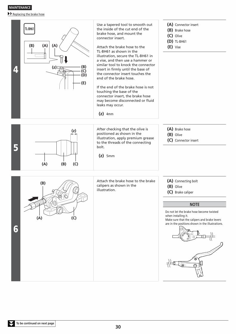
4 (z)
(B) (A)
(B)(C)(D)
(E)
(A)
Use a tapered tool to smooth out the inside of the cut end of the brake hose, and mount the connector insert.
Attach the brake hose to the TL-BH61 as shown in the illustration, secure the TL-BH61 in a vise, and then use a hammer or similar tool to knock the connector insert in firmly until the base of the connector insert touches the end of the brake hose.
If the end of the brake hose is not touching the base of the connector insert, the brake hose may become disconnected or fluid leaks may occur.
(z) 4mm
(A) Connector insert
(B) Brake hose
(C) Olive
(D) TL-BH61
(E) Vise
5
(z)
(A) (B) (C)
After checking that the olive is positioned as shown in the illustration, apply premium grease to the threads of the connecting bolt.
(z) 5mm
(A) Brake hose
(B) Olive
(C) Connector insert
6
(B)
(A) (C)
Attach the brake hose to the brake calipers as shown in the illustration.
(A) Connecting bolt
(B) Olive
(C) Brake caliper
NOTE
Do not let the brake hose become twisted when installing it.Make sure that the calipers and brake levers are in the positions shown in the illustrations.
MAINTENANCE
Replacing the brake hose
31
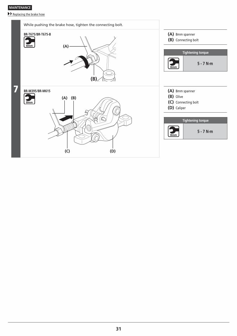
7
While pushing the brake hose, tighten the connecting bolt.
BR-T675/BR-T675-B
(A)
(B)
(A) 8mm spanner
(B) Connecting bolt
Tightening torque
5 - 7 N·m
BR-M395/BR-M615
(A) (B)
(C) (D)
(A) 8mm spanner
(B) Olive
(C) Connecting bolt
(D) Caliper
Tightening torque
5 - 7 N·m
MAINTENANCE
Replacing the brake hose
32
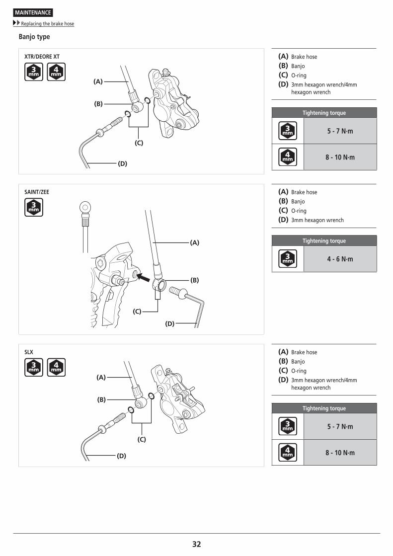
Banjo type
XTR/DEORE XT
(A)
(C)
(B)
(D)
(A) Brake hose
(B) Banjo
(C) O-ring
(D) 3mm hexagon wrench/4mm hexagon wrench
Tightening torque
5 - 7 N·m
8 - 10 N·m
SAINT/ZEE
(A)
(B)
(C)
(D)
(A) Brake hose
(B) Banjo
(C) O-ring
(D) 3mm hexagon wrench
Tightening torque
4 - 6 N·m
SLX
(A)
(C)
(B)
(D)
(A) Brake hose
(B) Banjo
(C) O-ring
(D) 3mm hexagon wrench/4mm hexagon wrench
Tightening torque
5 - 7 N·m
8 - 10 N·m
MAINTENANCE
Replacing the brake pads
33To be continued on next page
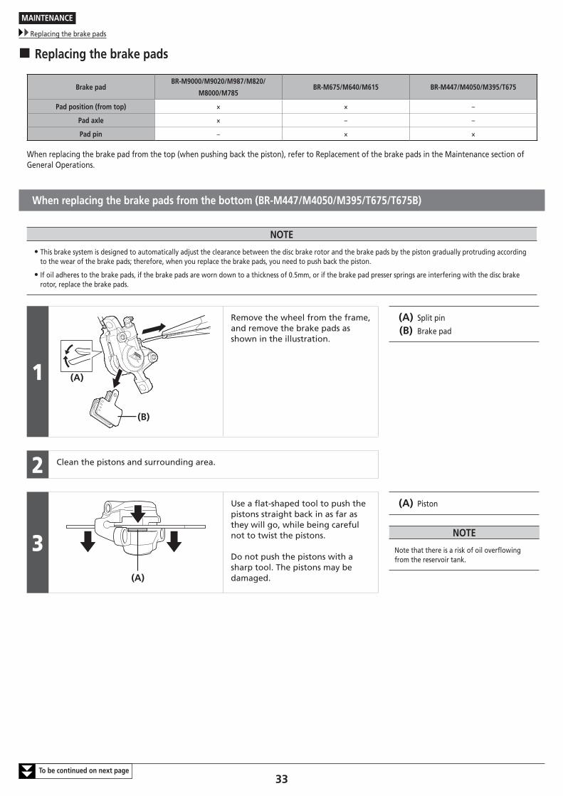
� Replacing the brake pads
Brake pad BR-M9000/M9020/M987/M820/
M8000/M785BR-M675/M640/M615 BR-M447/M4050/M395/T675
Pad position (from top) × × –
Pad axle × – –
Pad pin – × ×
When replacing the brake pad from the top (when pushing back the piston), refer to Replacement of the brake pads in the Maintenance section of General Operations.
When replacing the brake pads from the bottom (BR-M447/M4050/M395/T675/T675B)
NOTE
• This brake system is designed to automatically adjust the clearance between the disc brake rotor and the brake pads by the piston gradually protruding according to the wear of the brake pads; therefore, when you replace the brake pads, you need to push back the piston.
• If oil adheres to the brake pads, if the brake pads are worn down to a thickness of 0.5mm, or if the brake pad presser springs are interfering with the disc brake rotor, replace the brake pads.
1
(B)
(A)
Remove the wheel from the frame, and remove the brake pads as shown in the illustration.
(A) Split pin
(B) Brake pad
2 Clean the pistons and surrounding area.
3(A)
Use a flat-shaped tool to push the pistons straight back in as far as they will go, while being careful not to twist the pistons.
Do not push the pistons with a sharp tool. The pistons may be damaged.
(A) Piston
NOTE
Note that there is a risk of oil overflowing from the reservoir tank.
MAINTENANCE
Replacing the brake pads
34
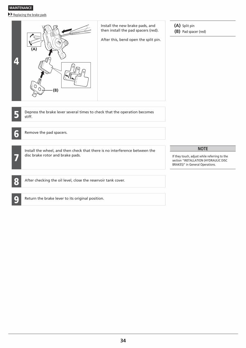
4
(B)
(A)
Install the new brake pads, and then install the pad spacers (red).
After this, bend open the split pin.
(A) Split pin
(B) Pad spacer (red)
5 Depress the brake lever several times to check that the operation becomes stiff.
6 Remove the pad spacers.
7Install the wheel, and then check that there is no interference between the disc brake rotor and brake pads.
NOTE
If they touch, adjust while referring to the section "INSTALLATION (HYDRAULIC DISC BRAKES)" in General Operations.
8 After checking the oil level, close the reservoir tank cover.
9 Return the brake lever to its original position.
MAINTENANCE
Designated parts for magnesium products
35
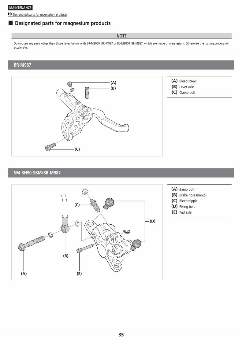
� Designated parts for magnesium products
NOTE
Do not use any parts other than those listed below with BR-M9000, BR-M987 or BL-M9000, BL-M987, which are made of magnesium. Otherwise the rusting process will accelerate.
BR-M987
(A)
(C)
(B)
(A) Bleed screw
(B) Lever axle
(C) Clamp bolt
SM-BH90-SBM/BR-M987
(A)
(B)
(E)
(C)
(D)
(A) Banjo bolt
(B) Brake hose (Banjo)
(C) Bleed nipple
(D) Fixing bolt
(E) Pad axle
MAINTENANCE
Designated parts for magnesium products
36
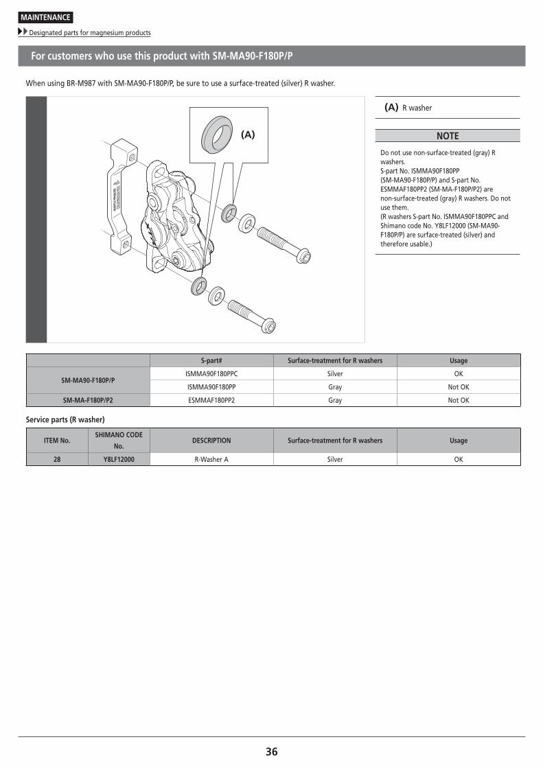
For customers who use this product with SM-MA90-F180P/P
When using BR-M987 with SM-MA90-F180P/P, be sure to use a surface-treated (silver) R washer.
(A)
(A) R washer
NOTE
Do not use non-surface-treated (gray) R washers. S-part No. ISMMA90F180PP (SM-MA90-F180P/P) and S-part No. ESMMAF180PP2 (SM-MA-F180P/P2) are non-surface-treated (gray) R washers. Do not use them. (R washers S-part No. ISMMA90F180PPC and Shimano code No. Y8LF12000 (SM-MA90-F180P/P) are surface-treated (silver) and therefore usable.)
S-part# Surface-treatment for R washers Usage
SM-MA90-F180P/PISMMA90F180PPC Silver OK
ISMMA90F180PP Gray Not OK
SM-MA-F180P/P2 ESMMAF180PP2 Gray Not OK
Service parts (R washer)
ITEM No. SHIMANO CODE
No.DESCRIPTION Surface-treatment for R washers Usage
28 Y8LF12000 R-Washer A Silver OK

Please note: specifications are subject to change for improvement without notice. (English) © May 2017 by Shimano Inc. ITP