Embed Size (px)
Citation preview
(English) DM-RADBR01-00
DURA-ACEST-R9120BR-R9170SM-RT900
Dealer's Manual
ROAD MTB Trekking
City Touring/Comfort Bike
URBAN SPORT E-BIKE
Hydraulic Disc Brake
2
CONTENTS
IMPORTANT NOTICE .............................................................................................. 3
TO ENSURE SAFETY ............................................................................................... 4
LIST OF TOOLS TO BE USED ................................................................................ 10
INSTALLATION ..................................................................................................... 12Installation of the disc brake rotor ...........................................................................................................12
Installation of the brake hose ...................................................................................................................12
Installation of the brake hose (easy hose joint system) ...........................................................................18
Installation to the handlebar ....................................................................................................................30
Adding Shimano genuine mineral oil and bleeding air ..........................................................................31
Installing the brake caliper ........................................................................................................................40
Temporary tightening of the frame fixing bolts ......................................................................................48
Installation of the shifting cable ...............................................................................................................49
ADJUSTMENT ...................................................................................................... 54Free stroke and reach adjustment ............................................................................................................54
MAINTENANCE .................................................................................................... 57Replacing the brake pads ..........................................................................................................................57
Replacement of the nameplate .................................................................................................................59
Shimano genuine mineral oil replacement ..............................................................................................59
Replacing the bracket cover ......................................................................................................................60
Replacing the main lever support .............................................................................................................61
Replacing the cable cover ..........................................................................................................................63
How to pull out a disconnected inner end (shifting cable) .....................................................................64
Replacement of the SL cable guide ...........................................................................................................65
3
IMPORTANT NOTICE
IMPORTANT NOTICE
• This dealer’s manual is intended primarily for use by professional bicycle mechanics. Users who are not professionally trained for bicycle assembly should not attempt to install the components themselves using the dealer’s manuals. If any part of the information on the manual is unclear to you, do not proceed with the installation. Instead, contact your place of purchase or a local bicycle dealer for their assistance.
• Make sure to read all instruction manuals included with the product.
• Do not disassemble or modify the product other than as stated in the information contained in this dealer’s manual.
• All dealer’s manuals and instruction manuals can be viewed on-line on our website (http://si.shimano.com).
• Please observe the appropriate rules and regulations of the country, state or region in which you conduct your business as a dealer.
For safety, be sure to read this dealer’s manual thoroughly before use, and follow it for correct use.
The following instructions must be observed at all times in order to prevent personal injury and physical damage to equipment and surroundings.The instructions are classified according to the degree of danger or damage which may occur if the product is used incorrectly.
DANGER
Failure to follow the instructions will result in death or serious injury.
WARNING
Failure to follow the instructions could result in death or serious injury.
CAUTION
Failure to follow the instructions could cause personal injury or physical damage to equipment and surroundings.
4
TO ENSURE SAFETY
TO ENSURE SAFETY
WARNING
• When installing components, be sure to follow the instructions that are given in the instruction manuals.It is recommended that you use only genuine Shimano parts. If parts such as bolts and nuts become loose or damaged, the bicycle may suddenly fall over, which may cause serious injury.In addition, if adjustments are not carried out correctly, problems may occur, and the bicycle may suddenly fall over, which may cause serious injury.
• Be sure to wear safety glasses or goggles to protect your eyes while performing maintenance tasks such as replacing parts.
• After reading the dealer's manual thoroughly, keep it in a safe place for later reference.
Be sure to also inform users of the following:
�Brake • Each bicycle may handle slightly differently depending on the model. Therefore, be sure to learn the proper braking technique (including brake lever pressure and bicycle control characteristics) and operation of your bicycle. Improper use of your bicycle's brake system may result in a loss of control or a fall, which could lead to severe injury. For proper operation, consult your professional bicycle dealer or the bicycle's owner's manual. It is also important to practice riding as well as braking operation, etc.
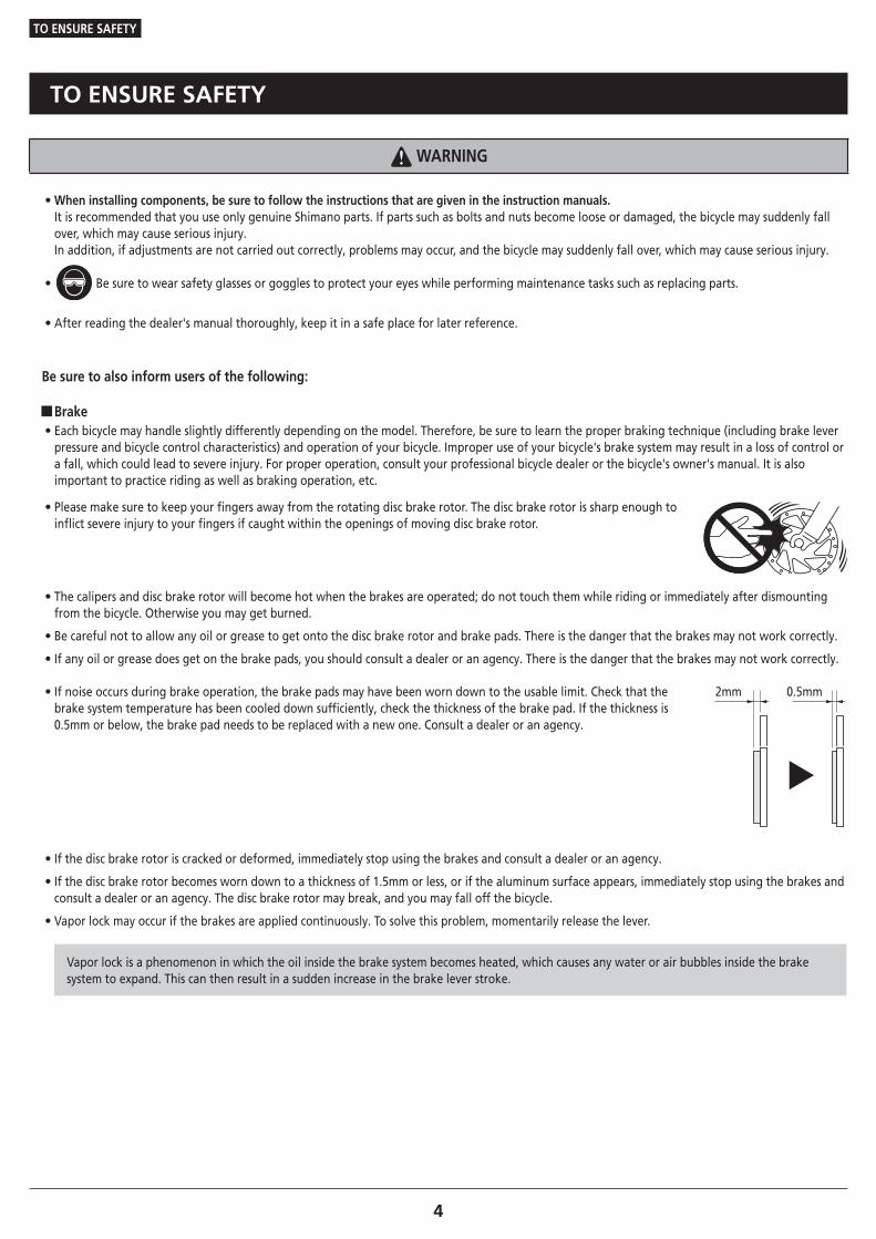
• Please make sure to keep your fingers away from the rotating disc brake rotor. The disc brake rotor is sharp enough to inflict severe injury to your fingers if caught within the openings of moving disc brake rotor.
• The calipers and disc brake rotor will become hot when the brakes are operated; do not touch them while riding or immediately after dismounting from the bicycle. Otherwise you may get burned.
• Be careful not to allow any oil or grease to get onto the disc brake rotor and brake pads. There is the danger that the brakes may not work correctly.
• If any oil or grease does get on the brake pads, you should consult a dealer or an agency. There is the danger that the brakes may not work correctly.
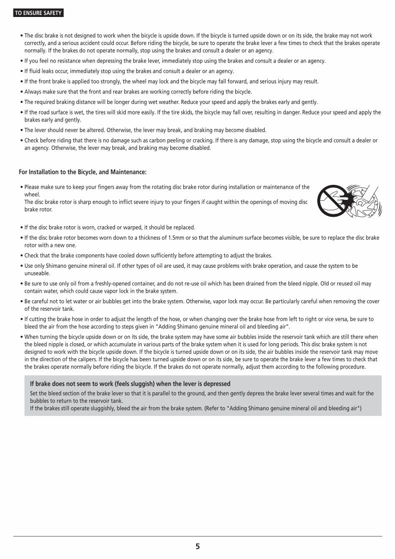
• If noise occurs during brake operation, the brake pads may have been worn down to the usable limit. Check that the brake system temperature has been cooled down sufficiently, check the thickness of the brake pad. If the thickness is 0.5mm or below, the brake pad needs to be replaced with a new one. Consult a dealer or an agency.
2mm 0.5mm
• If the disc brake rotor is cracked or deformed, immediately stop using the brakes and consult a dealer or an agency.
• If the disc brake rotor becomes worn down to a thickness of 1.5mm or less, or if the aluminum surface appears, immediately stop using the brakes and consult a dealer or an agency. The disc brake rotor may break, and you may fall off the bicycle.
• Vapor lock may occur if the brakes are applied continuously. To solve this problem, momentarily release the lever.
Vapor lock is a phenomenon in which the oil inside the brake system becomes heated, which causes any water or air bubbles inside the brake system to expand. This can then result in a sudden increase in the brake lever stroke.
5
TO ENSURE SAFETY
• The disc brake is not designed to work when the bicycle is upside down. If the bicycle is turned upside down or on its side, the brake may not work correctly, and a serious accident could occur. Before riding the bicycle, be sure to operate the brake lever a few times to check that the brakes operate normally. If the brakes do not operate normally, stop using the brakes and consult a dealer or an agency.
• If you feel no resistance when depressing the brake lever, immediately stop using the brakes and consult a dealer or an agency.
• If fluid leaks occur, immediately stop using the brakes and consult a dealer or an agency.
• If the front brake is applied too strongly, the wheel may lock and the bicycle may fall forward, and serious injury may result.
• Always make sure that the front and rear brakes are working correctly before riding the bicycle.
• The required braking distance will be longer during wet weather. Reduce your speed and apply the brakes early and gently.
• If the road surface is wet, the tires will skid more easily. If the tire skids, the bicycle may fall over, resulting in danger. Reduce your speed and apply the brakes early and gently.
• The lever should never be altered. Otherwise, the lever may break, and braking may become disabled.
• Check before riding that there is no damage such as carbon peeling or cracking. If there is any damage, stop using the bicycle and consult a dealer or an agency. Otherwise, the lever may break, and braking may become disabled.
For Installation to the Bicycle, and Maintenance:
• Please make sure to keep your fingers away from the rotating disc brake rotor during installation or maintenance of the wheel. The disc brake rotor is sharp enough to inflict severe injury to your fingers if caught within the openings of moving disc brake rotor.
• If the disc brake rotor is worn, cracked or warped, it should be replaced.
• If the disc brake rotor becomes worn down to a thickness of 1.5mm or so that the aluminum surface becomes visible, be sure to replace the disc brake rotor with a new one.
• Check that the brake components have cooled down sufficiently before attempting to adjust the brakes.
• Use only Shimano genuine mineral oil. If other types of oil are used, it may cause problems with brake operation, and cause the system to be unuseable.
• Be sure to use only oil from a freshly-opened container, and do not re-use oil which has been drained from the bleed nipple. Old or reused oil may contain water, which could cause vapor lock in the brake system.
• Be careful not to let water or air bubbles get into the brake system. Otherwise, vapor lock may occur. Be particularly careful when removing the cover of the reservoir tank.
• If cutting the brake hose in order to adjust the length of the hose, or when changing over the brake hose from left to right or vice versa, be sure to bleed the air from the hose according to steps given in “Adding Shimano genuine mineral oil and bleeding air”.
• When turning the bicycle upside down or on its side, the brake system may have some air bubbles inside the reservoir tank which are still there when the bleed nipple is closed, or which accumulate in various parts of the brake system when it is used for long periods. This disc brake system is not designed to work with the bicycle upside down. If the bicycle is turned upside down or on its side, the air bubbles inside the reservoir tank may move in the direction of the calipers. If the bicycle has been turned upside down or on its side, be sure to operate the brake lever a few times to check that the brakes operate normally before riding the bicycle. If the brakes do not operate normally, adjust them according to the following procedure.
If brake does not seem to work (feels sluggish) when the lever is depressedSet the bleed section of the brake lever so that it is parallel to the ground, and then gently depress the brake lever several times and wait for the bubbles to return to the reservoir tank.If the brakes still operate sluggishly, bleed the air from the brake system. (Refer to "Adding Shimano genuine mineral oil and bleeding air")
6
TO ENSURE SAFETY
• If the quick release lever on the hub is on the same side as the disc brake rotor, they may interfere with each other, which is dangerous, so check that they do not.
• Shimano disc brake systems are not compatible with tandem bicycles. Because tandem bicycles are heavier, the stress on the brake system increases during brake operation. If hydraulic disc brakes are used with tandem bicycles, the oil temperature will become too high and vapor locks or ruptures in the brake hoses may occur, and this will cause the brakes to fail.
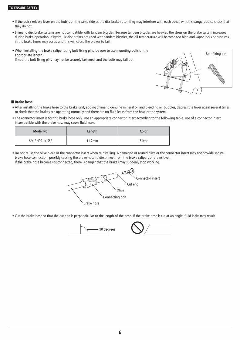
• When installing the brake caliper using bolt fixing pins, be sure to use mounting bolts of the appropriate length. If not, the bolt fixing pins may not be securely fastened, and the bolts may fall out.
Bolt fixing pin
�Brake hose • After installing the brake hose to the brake unit, adding Shimano genuine mineral oil and bleeding air bubbles, depress the lever again several times to check that the brakes are operating normally and there are no fluid leaks from the hose or the system.
• The connector insert is for this brake hose only. Use an appropriate connector insert according to the following table. Use of a connector insert incompatible with the brake hose may cause fluid leaks.
Model No. Length Color
SM-BH90-JK-SSR 11.2mm Silver
• Do not reuse the olive piece or the connector insert when reinstalling. A damaged or reused olive or the connector insert may not provide secure brake hose connection, possibly causing the brake hose to disconnect from the brake calipers or brake lever. If the brake hose becomes disconnected, there is danger that the brakes may suddenly stop working.
Brake hose
Connecting bolt
Olive
Cut end
Connector insert
• Cut the brake hose so that the cut end is perpendicular to the length of the hose. If the brake hose is cut at an angle, fluid leaks may result.
90 degrees
7
TO ENSURE SAFETY
CAUTION
Be sure to also inform users of the following:
�Cautions on the Shimano genuine mineral oil • Contact with eyes may result in irritation. In the event of contact with eye, wash with water and seek medical attention immediately.
• Contact with skin may cause a rash and discomfort. In the event of contact with skin, wash well with soap and water.
• Inhalation of Shimano genuine mineral oil mist or vapors may cause nausea. Cover nose and mouth with a respirator type mask and use in a well ventilated area. If Shimano genuine mineral oil vapor is inhaled, go immediately to an area with fresh air and cover up with a blanket. Lay down and keep warm, and seek professional medical attention if required.
�Burn-in period • Disc brakes have a burn-in period, and the braking force will gradually increase as the burn-in period progresses. Make sure that you are aware of any such increases in braking force when using the brakes during the burn-in period.
For Installation to the Bicycle, and Maintenance:
�Handling the Shimano genuine mineral oil • Contact with eyes may result in irritation. Use safety glasses when handling, and avoid contact with eyes. In the event of contact with eye, wash with water and seek medical attention immediately.
• Contact with skin may cause a rash and discomfort. Use gloves when handling. In the event of contact with skin, wash well with soap and water.
• Do not drink. May cause vomiting or diarrhea.
• Keep out of reach of children.
• Do not cut, let near heat, weld or pressurize the oil container, as this may cause explosion or fire.
• Disposal of Used Oil: Follow local county and/or state codes for disposal.
• Directions: Keep the container sealed to prevent foreign objects and moisture from getting inside, and store it in a cool, dark area away from direct sunlight or heat. Keep from heat or flame. Petroleum Class III, Danger level III
�When cleaning with a compressor • If disassembling the caliper body to clean the internal parts using a compressor, note that moisture from the compressed air may remain on the caliper components. Let the caliper components dry sufficiently before reassembling the calipers.
�Brake hose • When cutting the brake hose, handle the knife carefully so as not to cause injury.
• Be careful to avoid injury from the olive.
8
TO ENSURE SAFETY
NOTE
Be sure to also inform users of the following:
• Be sure to keep turning the crank during the gear shifting.
• Handle the products carefully, and avoid subjecting them to any strong shocks.
• Do not use thinners or similar substances to clean the products. Such substances may damage the surfaces.
• In the case of carbon levers, wash them with a soft cloth using a neutral detergent. Otherwise, the material may get damaged, and the strength may be affected.
• Avoid leaving the carbon levers in places where high temperatures are present. Also, keep them far away from fire.
• If gear shifting operations do not feel smooth, wash the derailleur and lubricate all moving parts.
• When the bicycle wheel has been removed, it is recommended that pad spacers are installed. Do not depress the brake lever while the wheel is removed. If the brake lever is depressed without the pad spacers installed, the pistons will protrude further than normal. If that happens, consult a dealer.
• Use soapy water and a dry cloth when cleaning and carrying out maintenance of the brake system. Do not use commercially available brake cleansers or silencing agents, as they can cause damage to parts such as seals.
• Products are not guaranteed against natural wear and deterioration from normal use and aging.
• For maximum performance we highly recommend Shimano lubricants and maintenance products.
For Installation to the Bicycle, and Maintenance: • Use a brake hose / outer casing which still has some length to spare even when the handlebars are turned all the way to both sides. Furthermore, check that the shifting lever does not touch the bicycle frame when the handlebars are turned all the way.
• Use an OT-SP cable and cable guide for smooth operation.
• Grease the inner cable and the inside of the outer casing before use to ensure that they slide properly. Do not let dust adhere on the inner cable. If the grease on the inner cable is wiped off, the application of SIS SP41 grease (Y04180000) is recommended.
• A special grease is used for the gear shifting cable. Do not use premium grease or other types of grease, otherwise they may cause deterioration in gear shifting performance.
• If gear shifting adjustments cannot be carried out, check that the rear fork ends are aligned. Also check if the cable is lubricated and if the outer casing is too long or too short.
• Do not remove the lever unit.
�Disc brake • If the brake caliper mounting boss and the fork end are not of standard dimensions, the disc brake rotor and caliper may touch.
• When the bicycle wheel has been removed, it is recommended that pad spacers are installed. The pad spacers will prevent the piston from coming out if the brake lever is depressed while the wheel is removed.
• If the brake lever is depressed without the pad spacers installed, the pistons will protrude further than is normal. Use a slotted screwdriver or similar tool to push back the brake pads, while being careful not to damage the surfaces of the brake pads. (If the brake pads are not installed, use a flat-shaped tool to push the pistons straight back in, while being careful not to damage them) If it is difficult to push the brake pads or pistons back, remove the bleed screws and then try again. (Note that some oil may overflow from the reservoir tank at this time.)
• Use isopropyl alcohol, soapy water or a dry cloth when cleaning and carrying out maintenance of the brake system. Do not use commercially available brake cleansers or silencing agents. They can cause damage to parts such as seals.
• Do not remove the pistons when disassembling the brake calipers.
• If the disc brake rotor is worn, cracked or warped, it should be replaced.
The actual product may differ from the illustration because this manual is intended chiefly to explain the procedures for using the product.
LIST OF TOOLS TO BE USED
10
LIST OF TOOLS TO BE USED
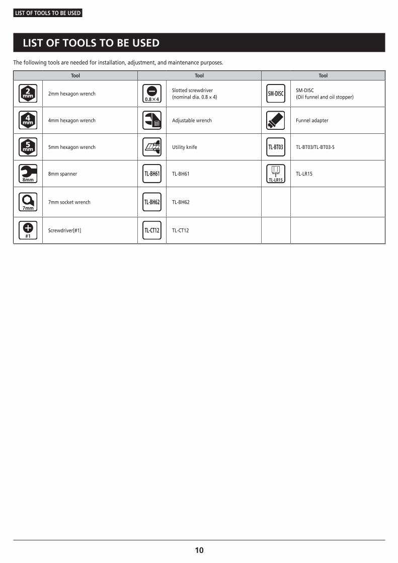
LIST OF TOOLS TO BE USED
The following tools are needed for installation, adjustment, and maintenance purposes.
Tool Tool Tool
2mm hexagon wrenchSlotted screwdriver (nominal dia. 0.8 × 4)
SM-DISC(Oil funnel and oil stopper)
4mm hexagon wrench Adjustable wrench Funnel adapter
5mm hexagon wrench Utility knife TL-BT03/TL-BT03-S
8mm spanner TL-BH61 TL-LR15
7mm socket wrench TL-BH62
Screwdriver[#1] TL-CT12
INSTALLATION
INSTALLATION
Installation of the disc brake rotor
12To be continued on next page
INSTALLATION
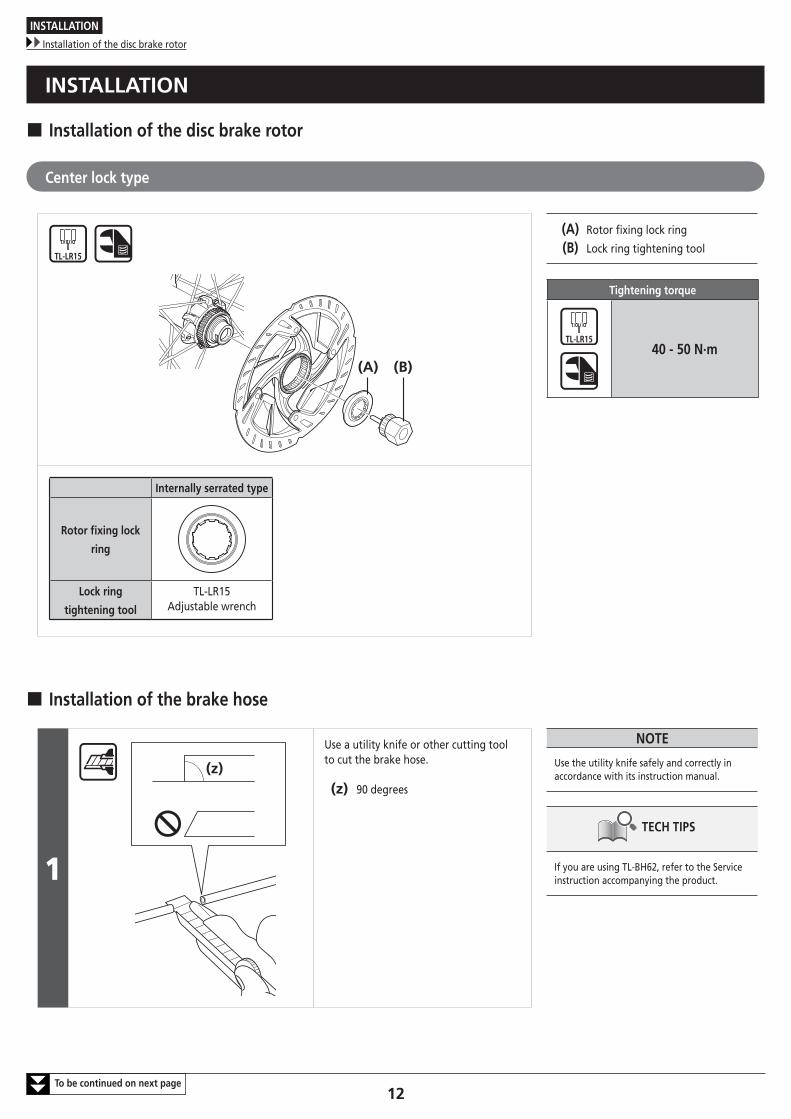
� Installation of the disc brake rotor
Center lock type
(A) (B)
(A) Rotor fixing lock ring
(B) Lock ring tightening tool
Tightening torque
40 - 50 N·m
Internally serrated type
Rotor fixing lock
ring
Lock ring
tightening tool
TL-LR15Adjustable wrench
� Installation of the brake hose
1
(z)
Use a utility knife or other cutting tool to cut the brake hose.
(z) 90 degrees
NOTE
Use the utility knife safely and correctly in accordance with its instruction manual.
TECH TIPS
If you are using TL-BH62, refer to the Service instruction accompanying the product.
INSTALLATION
Installation of the brake hose
13To be continued on next page
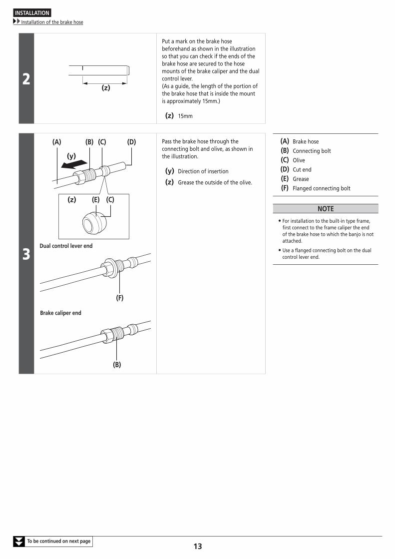
2(z)
Put a mark on the brake hose beforehand as shown in the illustration so that you can check if the ends of the brake hose are secured to the hose mounts of the brake caliper and the dual control lever. (As a guide, the length of the portion of the brake hose that is inside the mount is approximately 15mm.)
(z) 15mm
3
(D)(C)(B)(A)
(C)(E)(z)
(y)
Dual control lever end
(F)
Brake caliper end
(B)
Pass the brake hose through the connecting bolt and olive, as shown in the illustration.
(y) Direction of insertion
(z) Grease the outside of the olive.
(A) Brake hose
(B) Connecting bolt
(C) Olive
(D) Cut end
(E) Grease
(F) Flanged connecting bolt
NOTE
• For installation to the built-in type frame, first connect to the frame caliper the end of the brake hose to which the banjo is not attached.
• Use a flanged connecting bolt on the dual control lever end.
INSTALLATION
Installation of the brake hose
14To be continued on next page
4
(A) (C)
(A)(B)(D)(E)
(z)
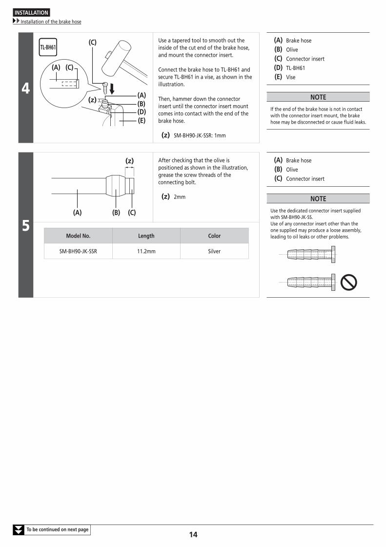
(C) Use a tapered tool to smooth out the inside of the cut end of the brake hose, and mount the connector insert.
Connect the brake hose to TL-BH61 and secure TL-BH61 in a vise, as shown in the illustration.
Then, hammer down the connector insert until the connector insert mount comes into contact with the end of the brake hose.
(z) SM-BH90-JK-SSR: 1mm
(A) Brake hose
(B) Olive
(C) Connector insert
(D) TL-BH61
(E) Vise
NOTE
If the end of the brake hose is not in contact with the connector insert mount, the brake hose may be disconnected or cause fluid leaks.
5(A) (B) (C)
(z) After checking that the olive is positioned as shown in the illustration, grease the screw threads of the connecting bolt.
(z) 2mm
(A) Brake hose
(B) Olive
(C) Connector insert
NOTE
Use the dedicated connector insert supplied with SM-BH90-JK-SS.Use of any connector insert other than the one supplied may produce a loose assembly, leading to oil leaks or other problems.Model No. Length Color
SM-BH90-JK-SSR 11.2mm Silver
INSTALLATION
Installation of the brake hose
15To be continued on next page
6
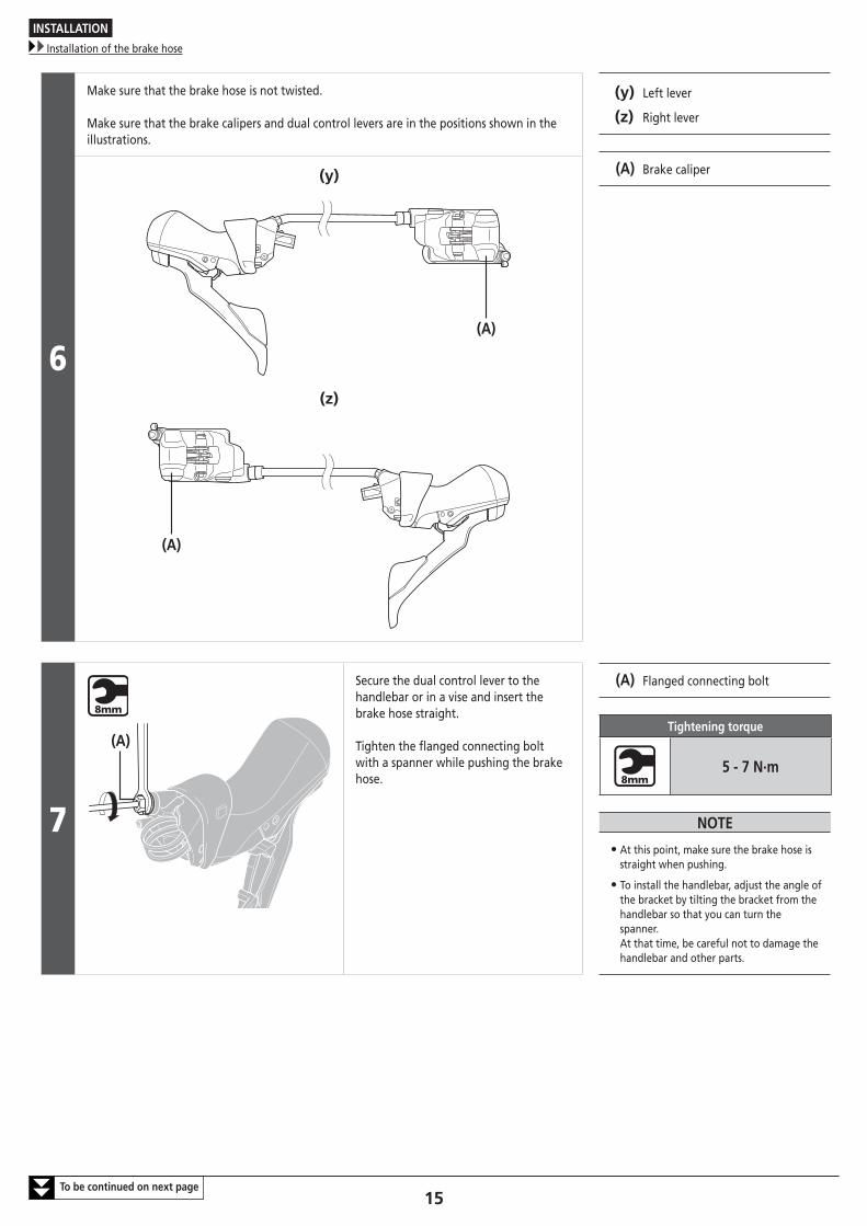
Make sure that the brake hose is not twisted.
Make sure that the brake calipers and dual control levers are in the positions shown in the illustrations.
(y) Left lever
(z) Right lever
(A) Brake caliper(y)
(A)
(z)
(A)
7
(A)
Secure the dual control lever to the handlebar or in a vise and insert the brake hose straight.
Tighten the flanged connecting bolt with a spanner while pushing the brake hose.
(A) Flanged connecting bolt
Tightening torque
5 - 7 N·m
NOTE
• At this point, make sure the brake hose is straight when pushing.
• To install the handlebar, adjust the angle of the bracket by tilting the bracket from the handlebar so that you can turn the spanner. At that time, be careful not to damage the handlebar and other parts.
INSTALLATION
Installation of the brake hose
16
8
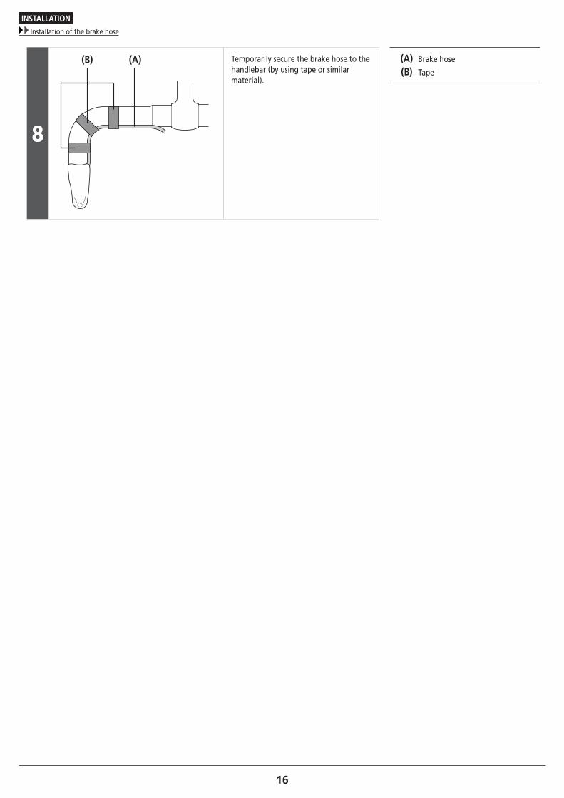
(B) (A) Temporarily secure the brake hose to the handlebar (by using tape or similar material).
(A) Brake hose
(B) Tape
INSTALLATION
Installation of the brake hose
17
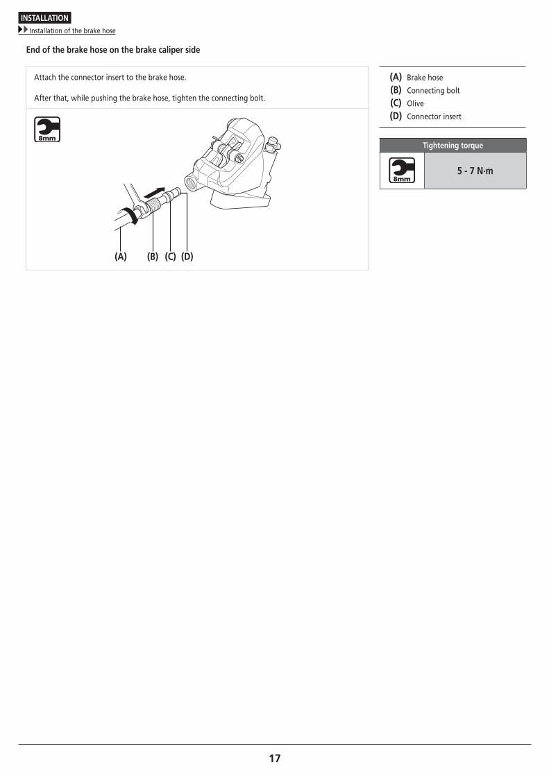
End of the brake hose on the brake caliper side
Attach the connector insert to the brake hose.
After that, while pushing the brake hose, tighten the connecting bolt.
(A) Brake hose
(B) Connecting bolt
(C) Olive
(D) Connector insert
Tightening torque
5 - 7 N·m
(A) (B) (C) (D)
INSTALLATION
Installation of the brake hose (easy hose joint system)
18To be continued on next page
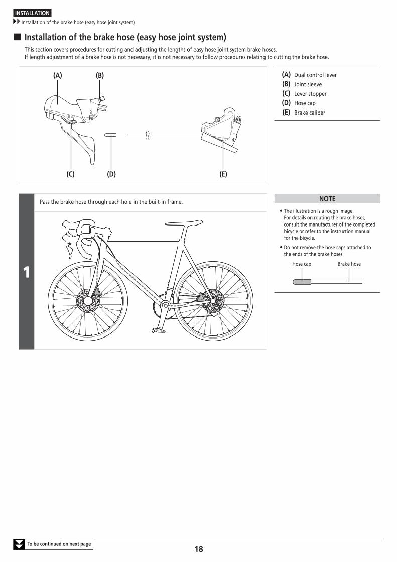
� Installation of the brake hose (easy hose joint system)This section covers procedures for cutting and adjusting the lengths of easy hose joint system brake hoses.If length adjustment of a brake hose is not necessary, it is not necessary to follow procedures relating to cutting the brake hose.
(A) (B)
(D)(C) (E)
(A) Dual control lever
(B) Joint sleeve
(C) Lever stopper
(D) Hose cap
(E) Brake caliper
1
Pass the brake hose through each hole in the built-in frame. NOTE
• The illustration is a rough image. For details on routing the brake hoses, consult the manufacturer of the completed bicycle or refer to the instruction manual for the bicycle.
• Do not remove the hose caps attached to the ends of the brake hoses.
Hose cap Brake hose
INSTALLATION
Installation of the brake hose (easy hose joint system)
19To be continued on next page
2
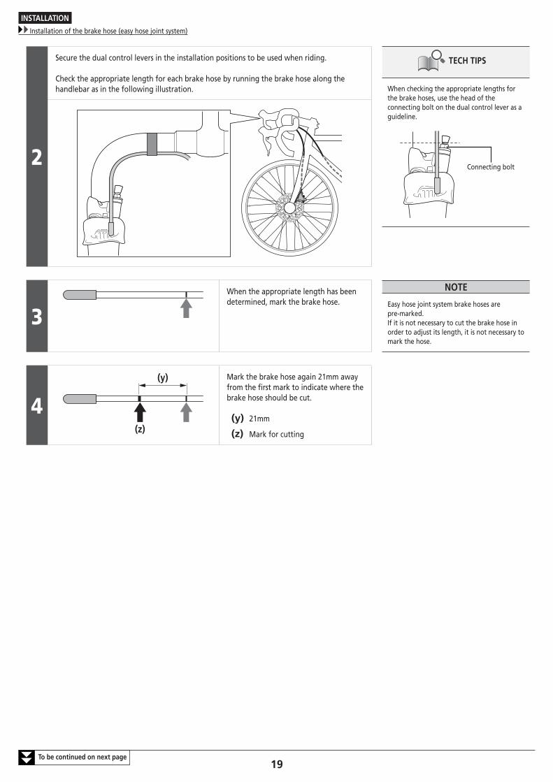
Secure the dual control levers in the installation positions to be used when riding.
Check the appropriate length for each brake hose by running the brake hose along the handlebar as in the following illustration.
TECH TIPS
When checking the appropriate lengths for the brake hoses, use the head of the connecting bolt on the dual control lever as a guideline.
Connecting bolt
3When the appropriate length has been determined, mark the brake hose.
NOTE
Easy hose joint system brake hoses are pre-marked.If it is not necessary to cut the brake hose in order to adjust its length, it is not necessary to mark the hose.
4(y)
(z)
Mark the brake hose again 21mm away from the first mark to indicate where the brake hose should be cut.
(y) 21mm
(z) Mark for cutting
INSTALLATION
Installation of the brake hose (easy hose joint system)
20To be continued on next page
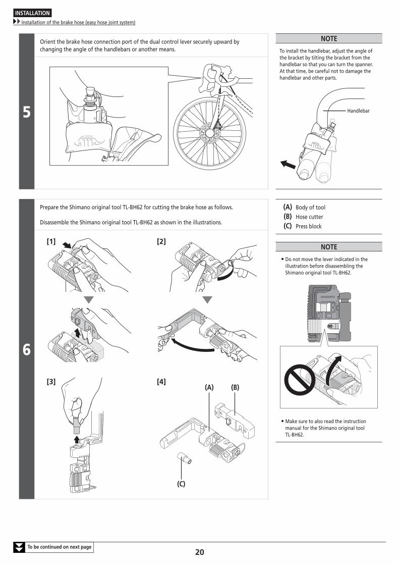
5
Orient the brake hose connection port of the dual control lever securely upward by changing the angle of the handlebars or another means.
NOTE
To install the handlebar, adjust the angle of the bracket by tilting the bracket from the handlebar so that you can turn the spanner.At that time, be careful not to damage the handlebar and other parts.
Handlebar
6
Prepare the Shimano original tool TL-BH62 for cutting the brake hose as follows.
Disassemble the Shimano original tool TL-BH62 as shown in the illustrations.
(A) Body of tool
(B) Hose cutter
(C) Press block
NOTE
• Do not move the lever indicated in the illustration before disassembling the Shimano original tool TL-BH62.
• Make sure to also read the instruction manual for the Shimano original tool TL-BH62.
[1] [2]
[3] [4]
(C)
(A) (B)
INSTALLATION
Installation of the brake hose (easy hose joint system)
21To be continued on next page
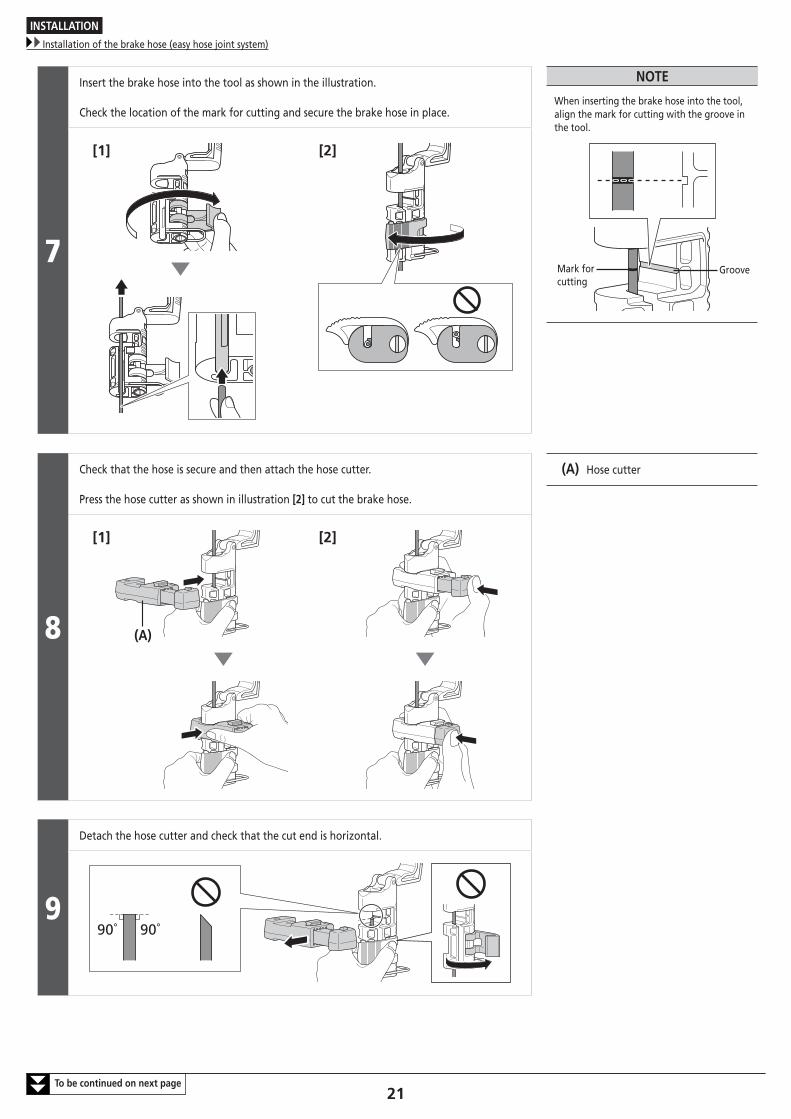
7
Insert the brake hose into the tool as shown in the illustration.
Check the location of the mark for cutting and secure the brake hose in place.
NOTE
When inserting the brake hose into the tool, align the mark for cutting with the groove in the tool.
GrooveMark for cutting
[1] [2]
8
Check that the hose is secure and then attach the hose cutter.
Press the hose cutter as shown in illustration [2] to cut the brake hose.
(A) Hose cutter
[1] [2]
(A)
9
Detach the hose cutter and check that the cut end is horizontal.
90˚ 90˚
INSTALLATION
Installation of the brake hose (easy hose joint system)
22To be continued on next page
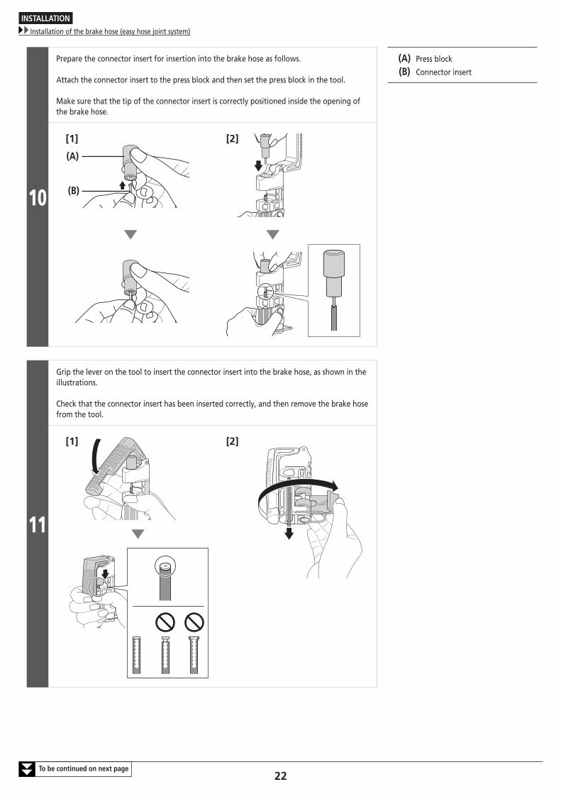
10
Prepare the connector insert for insertion into the brake hose as follows.
Attach the connector insert to the press block and then set the press block in the tool.
Make sure that the tip of the connector insert is correctly positioned inside the opening of the brake hose.
(A) Press block
(B) Connector insert
[1] [2]
(A)
(B)
11
Grip the lever on the tool to insert the connector insert into the brake hose, as shown in the illustrations.
Check that the connector insert has been inserted correctly, and then remove the brake hose from the tool.
[1] [2]
INSTALLATION
Installation of the brake hose (easy hose joint system)
23To be continued on next page
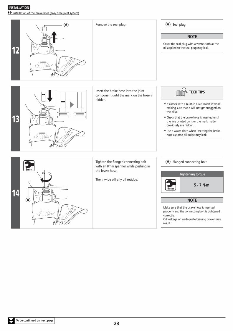
12
(A) Remove the seal plug. (A) Seal plug
NOTE
Cover the seal plug with a waste cloth as the oil applied to the seal plug may leak.
13
Insert the brake hose into the joint component until the mark on the hose is hidden.
TECH TIPS
• It comes with a built-in olive. Insert it while making sure that it will not get snagged on the olive.
• Check that the brake hose is inserted until the line printed on it or the mark made previously are hidden.
• Use a waste cloth when inserting the brake hose as some oil inside may leak.
14(A)
Tighten the flanged connecting bolt with an 8mm spanner while pushing in the brake hose.
Then, wipe off any oil residue.
(A) Flanged connecting bolt
Tightening torque
5 - 7 N·m
NOTE
Make sure that the brake hose is inserted properly and the connecting bolt is tightened correctly.Oil leakage or inadequate braking power may result.
INSTALLATION
Installation of the brake hose (easy hose joint system)
24To be continued on next page
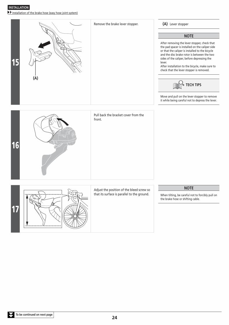
15
(A)
Remove the brake lever stopper. (A) Lever stopper
NOTE
After removing the lever stopper, check that the pad spacer is installed on the caliper side or that the caliper is installed to the bicycle and the disc brake rotor is between the two sides of the caliper, before depressing the lever.After installation to the bicycle, make sure to check that the lever stopper is removed.
TECH TIPS
Move and pull on the lever stopper to remove it while being careful not to depress the lever.
16
Pull back the bracket cover from the front.
17
Adjust the position of the bleed screw so that its surface is parallel to the ground.
NOTE
When tilting, be careful not to forcibly pull on the brake hose or shifting cable.
INSTALLATION
Installation of the brake hose (easy hose joint system)
25To be continued on next page
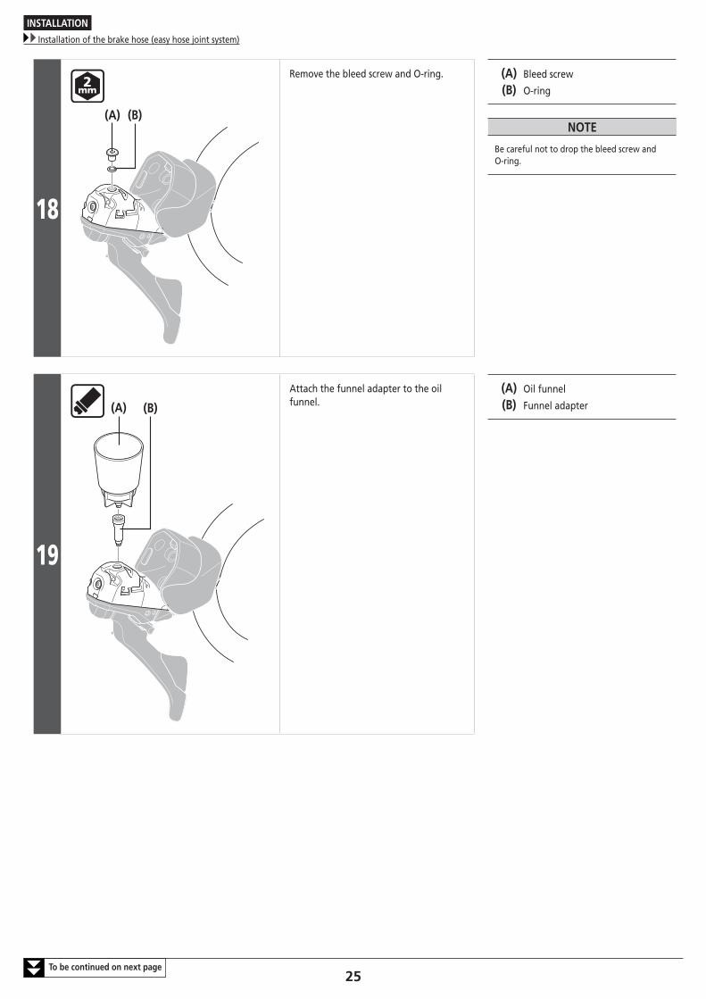
18
(A) (B)
Remove the bleed screw and O-ring. (A) Bleed screw
(B) O-ring
NOTE
Be careful not to drop the bleed screw and O-ring.
19
(A) (B)
Attach the funnel adapter to the oil funnel.
(A) Oil funnel
(B) Funnel adapter
INSTALLATION
Installation of the brake hose (easy hose joint system)
26To be continued on next page
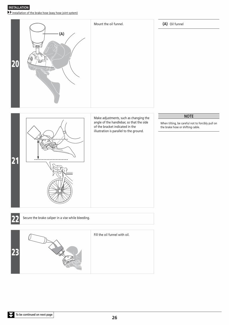
20
(A)
Mount the oil funnel. (A) Oil funnel
21
Make adjustments, such as changing the angle of the handlebar, so that the side of the bracket indicated in the illustration is parallel to the ground.
NOTE
When tilting, be careful not to forcibly pull on the brake hose or shifting cable.
22 Secure the brake caliper in a vise while bleeding.
23
Fill the oil funnel with oil.
INSTALLATION
Installation of the brake hose (easy hose joint system)
27To be continued on next page
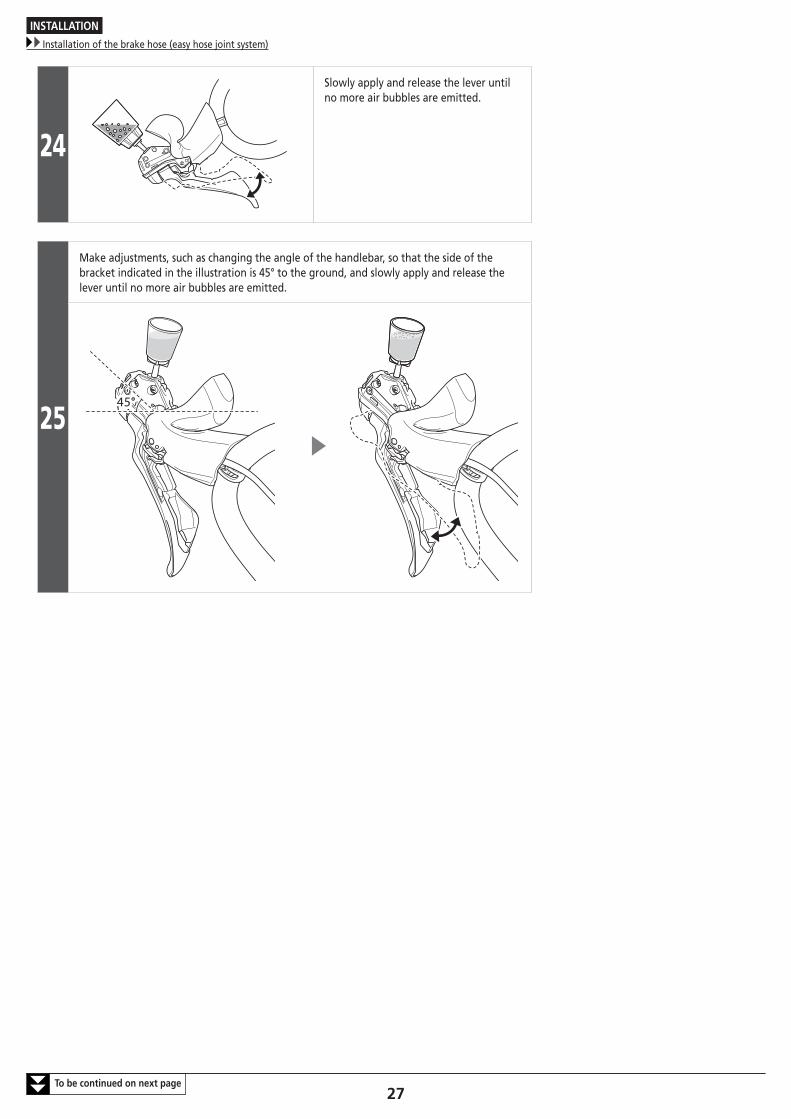
24
Slowly apply and release the lever until no more air bubbles are emitted.
25
Make adjustments, such as changing the angle of the handlebar, so that the side of the bracket indicated in the illustration is 45° to the ground, and slowly apply and release the lever until no more air bubbles are emitted.
45°

INSTALLATION
Installation of the brake hose (easy hose joint system)
28To be continued on next page
26
If the brake lever is then operated, air bubbles in the system will rise up through the port into the oil funnel.
Once the bubbles stop appearing, depress the brake lever as far as it will go.
Under the normal condition, the lever action should feel stiff at this point.
(x) Loose
(y) Slightly stiff
(z) Stiff
Lever operation
(x) (y) (z)
27
Make adjustments, such as changing the angle of the handlebar, so that the head of the bleed screw is parallel to the ground.

INSTALLATION
Installation of the brake hose (easy hose joint system)
29
28
(B)
(A)
Plug the oil funnel with the oil stopper so that the O-ring mounted side is facing downward.
(A) O-ring
(B) Oil stopper
29
Remove the oil funnel and funnel adapter while still plugged with the oil stopper.
Attach the O-ring to the bleed screw and tighten it while letting oil flow out so as to make sure that no air bubbles remain inside the reservoir tank.
Tightening torque
0.5 - 0.7 N·m
NOTE
• Do not operate the brake lever. Otherwise, air bubbles may enter the cylinder.
• Use a waste cloth to prevent the oil from flowing to surrounding areas.
30
Wipe away any oil which has flowed out. NOTE
After completing all procedures, make sure to check that the brakes work correctly.
INSTALLATION
Installation to the handlebar
30
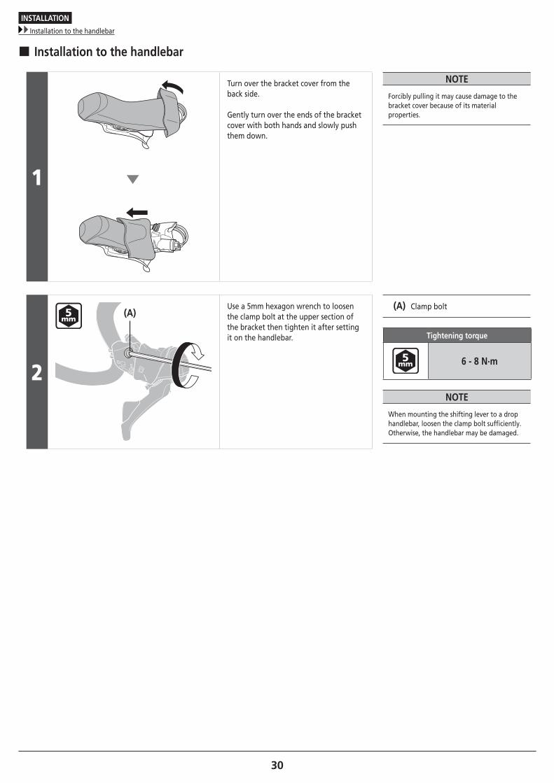
� Installation to the handlebar
1
Turn over the bracket cover from the back side. Gently turn over the ends of the bracket cover with both hands and slowly push them down.
NOTE
Forcibly pulling it may cause damage to the bracket cover because of its material properties.
2
(A)Use a 5mm hexagon wrench to loosen the clamp bolt at the upper section of the bracket then tighten it after setting it on the handlebar.
(A) Clamp bolt
Tightening torque
6 - 8 N·m
NOTE
When mounting the shifting lever to a drop handlebar, loosen the clamp bolt sufficiently.Otherwise, the handlebar may be damaged.
INSTALLATION
Adding Shimano genuine mineral oil and bleeding air
31To be continued on next page
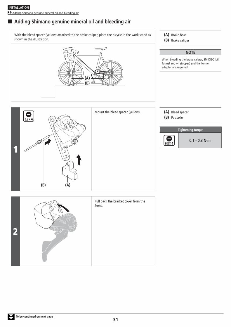
� Adding Shimano genuine mineral oil and bleeding air
With the bleed spacer (yellow) attached to the brake caliper, place the bicycle in the work stand as shown in the illustration.
(A) Brake hose
(B) Brake caliper
NOTE
When bleeding the brake caliper, SM-DISC (oil funnel and oil stopper) and the funnel adapter are required.
(A)(B)
1
(B) (A)
Mount the bleed spacer (yellow). (A) Bleed spacer
(B) Pad axle
Tightening torque
0.1 - 0.3 N·m
2
Pull back the bracket cover from the front.
INSTALLATION
Adding Shimano genuine mineral oil and bleeding air
32To be continued on next page
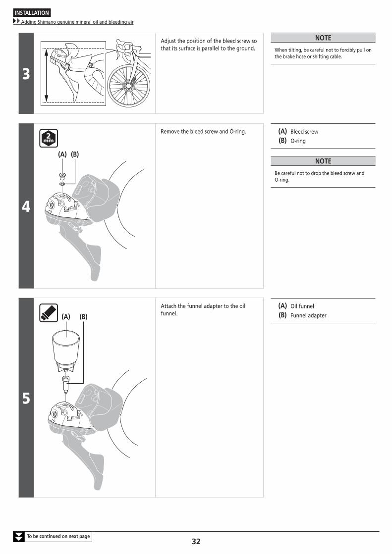
3
Adjust the position of the bleed screw so that its surface is parallel to the ground.
NOTE
When tilting, be careful not to forcibly pull on the brake hose or shifting cable.
4
(A) (B)
Remove the bleed screw and O-ring. (A) Bleed screw
(B) O-ring
NOTE
Be careful not to drop the bleed screw and O-ring.
5
(A) (B)
Attach the funnel adapter to the oil funnel.
(A) Oil funnel
(B) Funnel adapter
INSTALLATION
Adding Shimano genuine mineral oil and bleeding air
33To be continued on next page
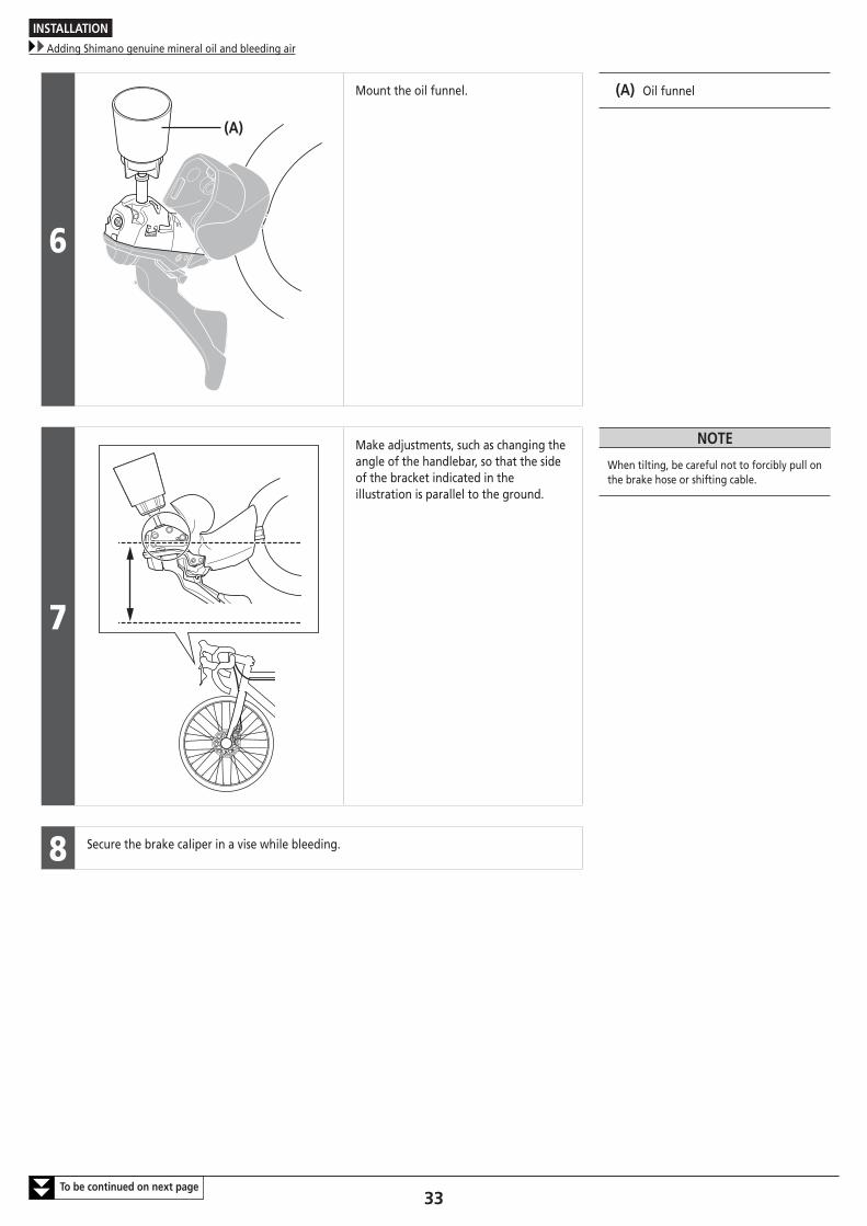
6
(A)
Mount the oil funnel. (A) Oil funnel
7
Make adjustments, such as changing the angle of the handlebar, so that the side of the bracket indicated in the illustration is parallel to the ground.
NOTE
When tilting, be careful not to forcibly pull on the brake hose or shifting cable.
8 Secure the brake caliper in a vise while bleeding.
INSTALLATION
Adding Shimano genuine mineral oil and bleeding air
34To be continued on next page
9 (A)
(B)
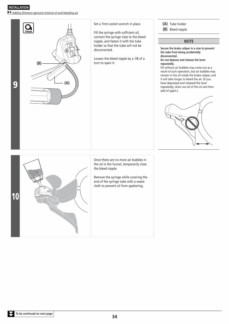
Set a 7mm socket wrench in place.
Fill the syringe with sufficient oil, connect the syringe tube to the bleed nipple, and fasten it with the tube holder so that the tube will not be disconnected.
Loosen the bleed nipple by a 1/8 of a turn to open it.
(A) Tube holder
(B) Bleed nipple
NOTE
Secure the brake caliper in a vise to prevent the tube from being accidentally disconnected.Do not depress and release the lever repeatedly.Oil without air bubbles may come out as a result of such operation, but air bubbles may remain in the oil inside the brake caliper, and it will take longer to bleed the air. (If you have depressed and released the lever repeatedly, drain out all of the oil and then add oil again.)
10
Once there are no more air bubbles in the oil in the funnel, temporarily close the bleed nipple.
Remove the syringe while covering the end of the syringe tube with a waste cloth to prevent oil from spattering.
INSTALLATION
Adding Shimano genuine mineral oil and bleeding air
35To be continued on next page
11
(A)
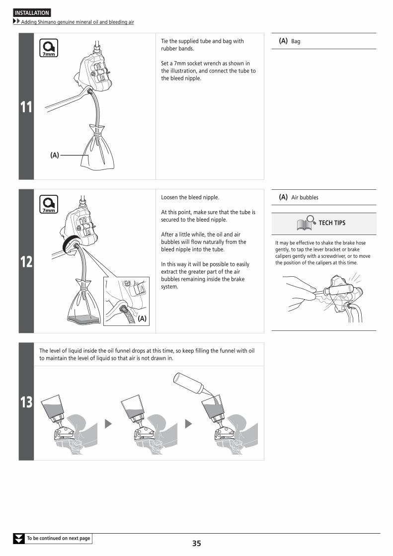
Tie the supplied tube and bag with rubber bands.
Set a 7mm socket wrench as shown in the illustration, and connect the tube to the bleed nipple.
(A) Bag
12
(A)
Loosen the bleed nipple.
At this point, make sure that the tube is secured to the bleed nipple.
After a little while, the oil and air bubbles will flow naturally from the bleed nipple into the tube.
In this way it will be possible to easily extract the greater part of the air bubbles remaining inside the brake system.
(A) Air bubbles
TECH TIPS
It may be effective to shake the brake hose gently, to tap the lever bracket or brake calipers gently with a screwdriver, or to move the position of the calipers at this time.
13
The level of liquid inside the oil funnel drops at this time, so keep filling the funnel with oil to maintain the level of liquid so that air is not drawn in.
INSTALLATION
Adding Shimano genuine mineral oil and bleeding air
36To be continued on next page
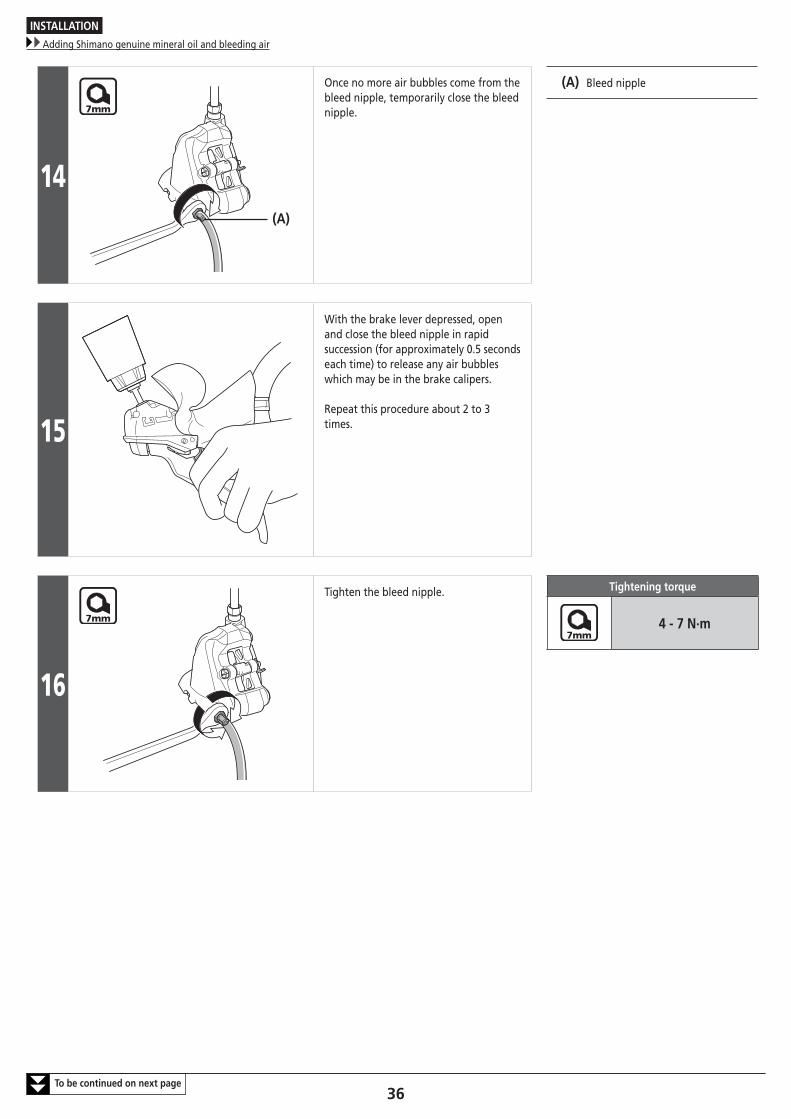
14(A)
Once no more air bubbles come from the bleed nipple, temporarily close the bleed nipple.
(A) Bleed nipple
15
With the brake lever depressed, open and close the bleed nipple in rapid succession (for approximately 0.5 seconds each time) to release any air bubbles which may be in the brake calipers.
Repeat this procedure about 2 to 3 times.
16
Tighten the bleed nipple. Tightening torque
4 - 7 N·m
INSTALLATION
Adding Shimano genuine mineral oil and bleeding air
37To be continued on next page
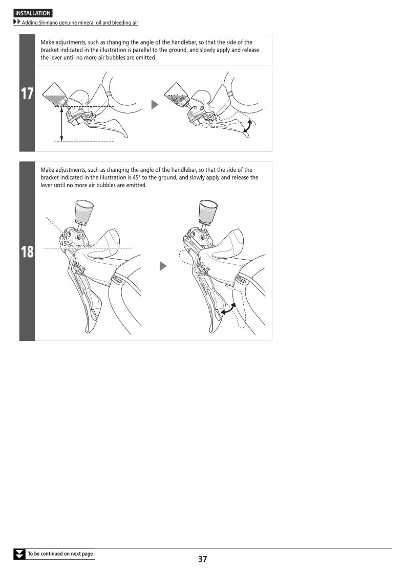
17
Make adjustments, such as changing the angle of the handlebar, so that the side of the bracket indicated in the illustration is parallel to the ground, and slowly apply and release the lever until no more air bubbles are emitted.
18
Make adjustments, such as changing the angle of the handlebar, so that the side of the bracket indicated in the illustration is 45° to the ground, and slowly apply and release the lever until no more air bubbles are emitted.
45°
INSTALLATION
Adding Shimano genuine mineral oil and bleeding air
38To be continued on next page
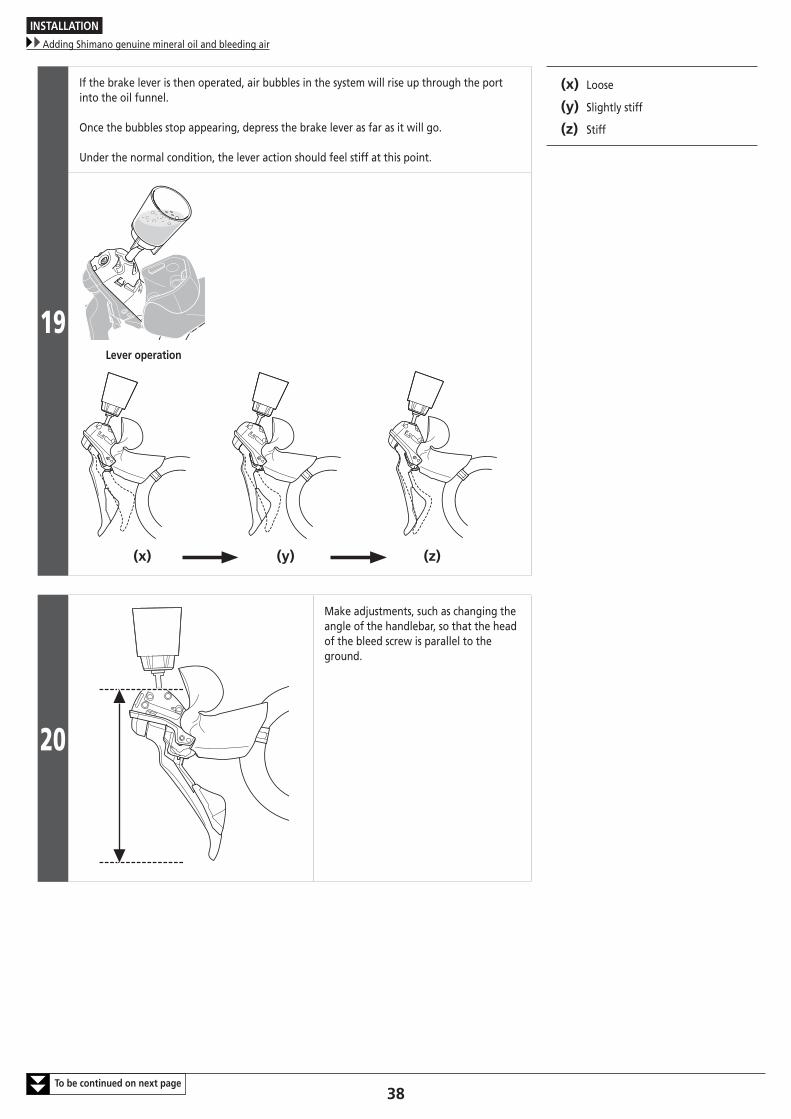
19
If the brake lever is then operated, air bubbles in the system will rise up through the port into the oil funnel.
Once the bubbles stop appearing, depress the brake lever as far as it will go.
Under the normal condition, the lever action should feel stiff at this point.
(x) Loose
(y) Slightly stiff
(z) Stiff
Lever operation
(x) (y) (z)
20
Make adjustments, such as changing the angle of the handlebar, so that the head of the bleed screw is parallel to the ground.
INSTALLATION
Adding Shimano genuine mineral oil and bleeding air
39
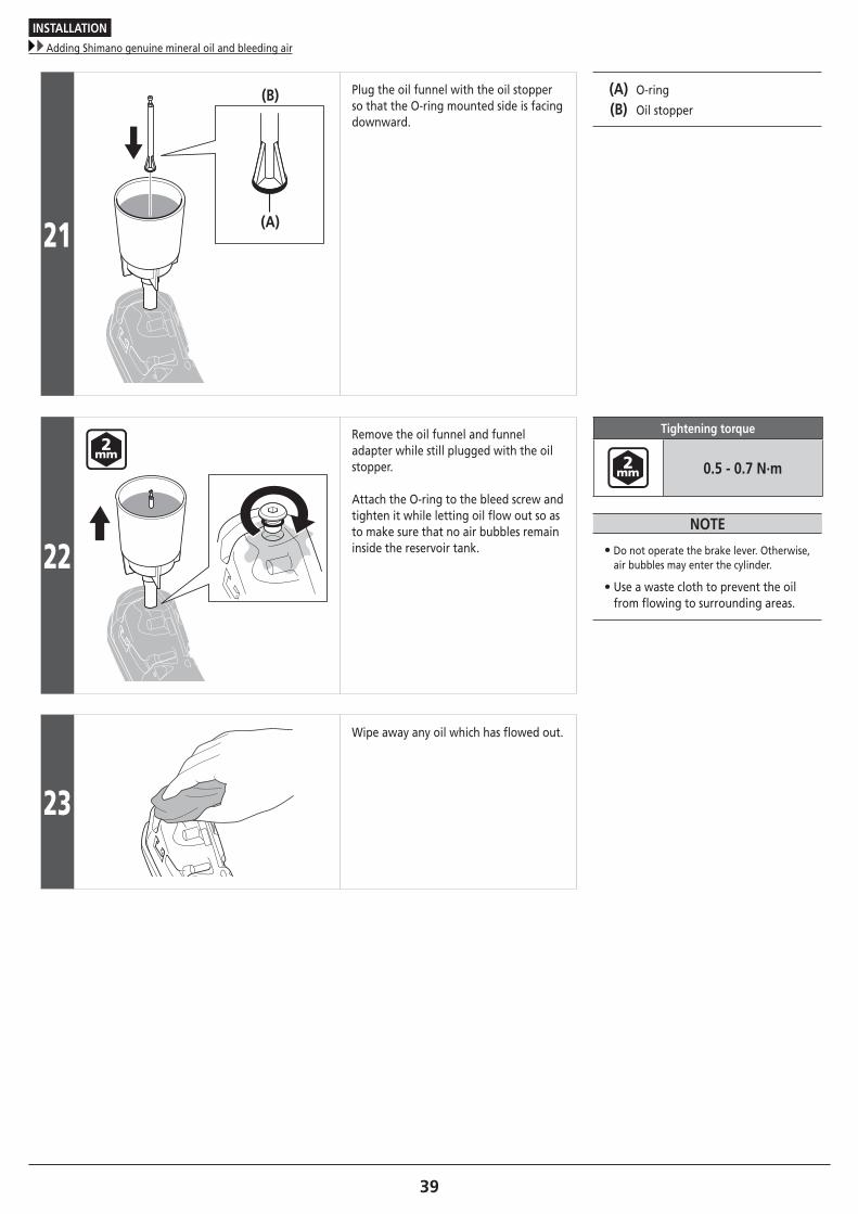
21
(B)
(A)
Plug the oil funnel with the oil stopper so that the O-ring mounted side is facing downward.
(A) O-ring
(B) Oil stopper
22
Remove the oil funnel and funnel adapter while still plugged with the oil stopper.
Attach the O-ring to the bleed screw and tighten it while letting oil flow out so as to make sure that no air bubbles remain inside the reservoir tank.
Tightening torque
0.5 - 0.7 N·m
NOTE
• Do not operate the brake lever. Otherwise, air bubbles may enter the cylinder.
• Use a waste cloth to prevent the oil from flowing to surrounding areas.
23
Wipe away any oil which has flowed out.
INSTALLATION
Installing the brake caliper
40
� Installing the brake caliper
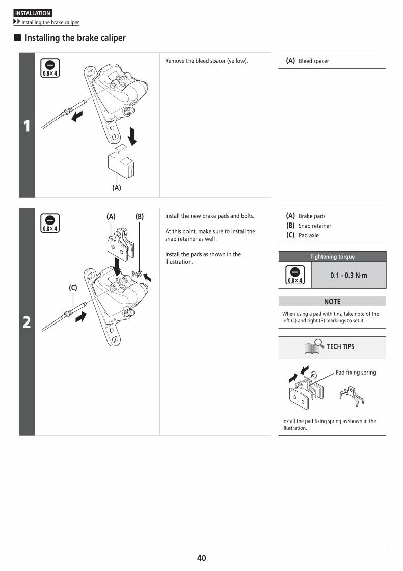
1
(A)
Remove the bleed spacer (yellow). (A) Bleed spacer
2
(C)
(B)(A) Install the new brake pads and bolts.
At this point, make sure to install the snap retainer as well.
Install the pads as shown in the illustration.
(A) Brake pads
(B) Snap retainer
(C) Pad axle
Tightening torque
0.1 - 0.3 N·m
NOTE
When using a pad with fins, take note of the left (L) and right (R) markings to set it.
TECH TIPS
Pad fixing spring
Install the pad fixing spring as shown in the illustration.
INSTALLATION
Installing the brake caliper
41
Check the length of brake caliper mounting bolt C
Rear (same for both 140mm and 160mm)
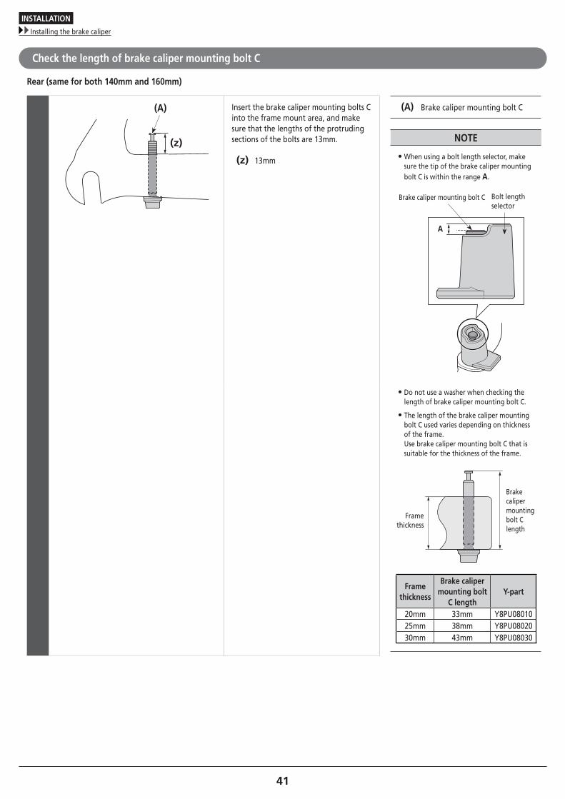
(A)
(z)
Insert the brake caliper mounting bolts C into the frame mount area, and make sure that the lengths of the protruding sections of the bolts are 13mm.
(z) 13mm
(A) Brake caliper mounting bolt C
NOTE
• When using a bolt length selector, make sure the tip of the brake caliper mounting bolt C is within the range A.
A
Brake caliper mounting bolt C Bolt length selector
• Do not use a washer when checking the length of brake caliper mounting bolt C.
• The length of the brake caliper mounting bolt C used varies depending on thickness of the frame. Use brake caliper mounting bolt C that is suitable for the thickness of the frame.
Brake caliper mounting bolt C length
Frame thickness
Frame thickness
Brake caliper mounting bolt
C lengthY-part
20mm 33mm Y8PU0801025mm 38mm Y8PU0802030mm 43mm Y8PU08030
INSTALLATION
Installing the brake caliper
42To be continued on next page
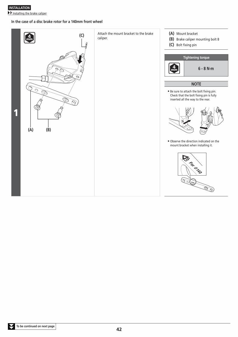
In the case of a disc brake rotor for a 140mm front wheel
1
(A) (B)
(C) Attach the mount bracket to the brake caliper.
(A) Mount bracket
(B) Brake caliper mounting bolt B
(C) Bolt fixing pin
Tightening torque
6 - 8 N·m
NOTE
• Be sure to attach the bolt fixing pin. Check that the bolt fixing pin is fully inserted all the way to the rear.
• Observe the direction indicated on the mount bracket when installing it.
INSTALLATION
Installing the brake caliper
43
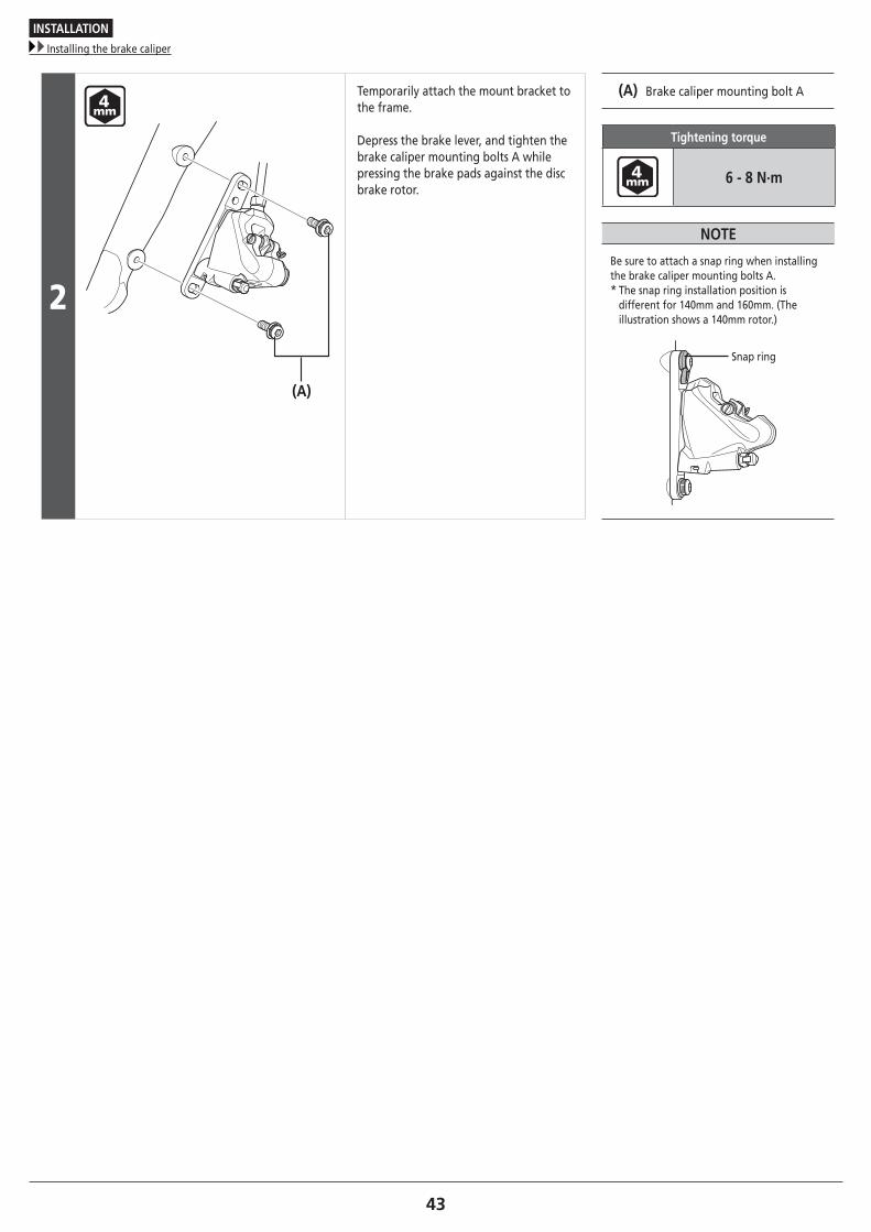
2
(A)
Temporarily attach the mount bracket to the frame.
Depress the brake lever, and tighten the brake caliper mounting bolts A while pressing the brake pads against the disc brake rotor.
(A) Brake caliper mounting bolt A
Tightening torque
6 - 8 N·m
NOTE
Be sure to attach a snap ring when installing the brake caliper mounting bolts A.* The snap ring installation position is
different for 140mm and 160mm. (The illustration shows a 140mm rotor.)
Snap ring
INSTALLATION
Installing the brake caliper
44To be continued on next page
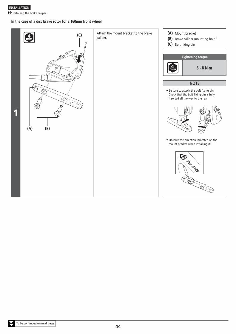
In the case of a disc brake rotor for a 160mm front wheel
1(B)
(C)
(A)
Attach the mount bracket to the brake caliper.
(A) Mount bracket
(B) Brake caliper mounting bolt B
(C) Bolt fixing pin
Tightening torque
6 - 8 N·m
NOTE
• Be sure to attach the bolt fixing pin. Check that the bolt fixing pin is fully inserted all the way to the rear.
• Observe the direction indicated on the mount bracket when installing it.

INSTALLATION
Installing the brake caliper
45
2
(A)
Temporarily attach the mount bracket to the frame.
Depress the brake lever, and tighten the brake caliper mounting bolts A while pressing the brake pads against the disc brake rotor.
(A) Brake caliper mounting bolt A
Tightening torque
6 - 8 N·m
NOTE
Be sure to attach a snap ring when installing the brake caliper mounting bolts A.* The snap ring installation position is
different for 140mm and 160mm. (The illustration shows a 160mm rotor.)
Snap ring
INSTALLATION
Installing the brake caliper
46To be continued on next page
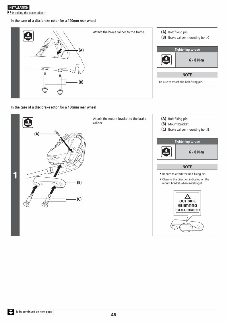
In the case of a disc brake rotor for a 140mm rear wheel
(B)
(A)
Attach the brake caliper to the frame. (A) Bolt fixing pin
(B) Brake caliper mounting bolt C
Tightening torque
6 - 8 N·m
NOTE
Be sure to attach the bolt fixing pin.
In the case of a disc brake rotor for a 160mm rear wheel
1
(A)
(B)
(C)
Attach the mount bracket to the brake caliper.
(A) Bolt fixing pin
(B) Mount bracket
(C) Brake caliper mounting bolt B
Tightening torque
6 - 8 N·m
NOTE
• Be sure to attach the bolt fixing pin.
• Observe the direction indicated on the mount bracket when installing it.
INSTALLATION
Installing the brake caliper
47
2(B)
(A)
(C)
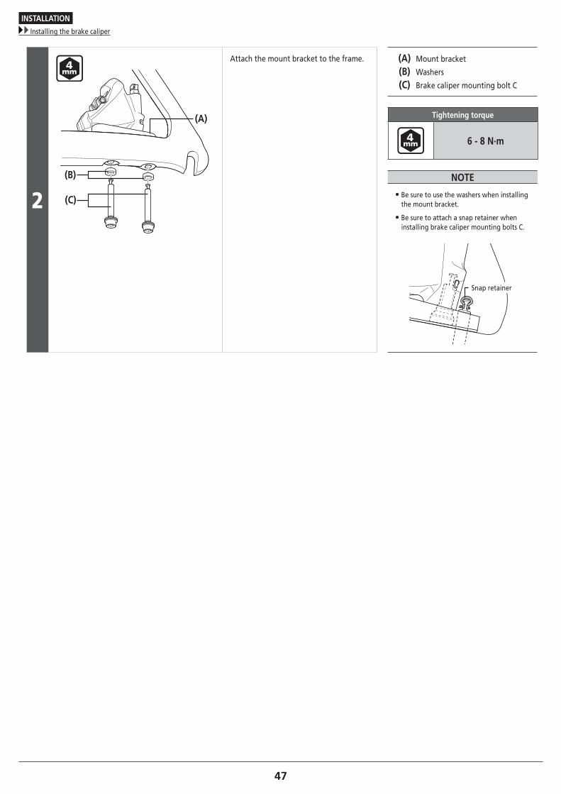
Attach the mount bracket to the frame. (A) Mount bracket
(B) Washers
(C) Brake caliper mounting bolt C
Tightening torque
6 - 8 N·m
NOTE
• Be sure to use the washers when installing the mount bracket.
• Be sure to attach a snap retainer when installing brake caliper mounting bolts C.
Snap retainer
INSTALLATION
Temporary tightening of the frame fixing bolts
48
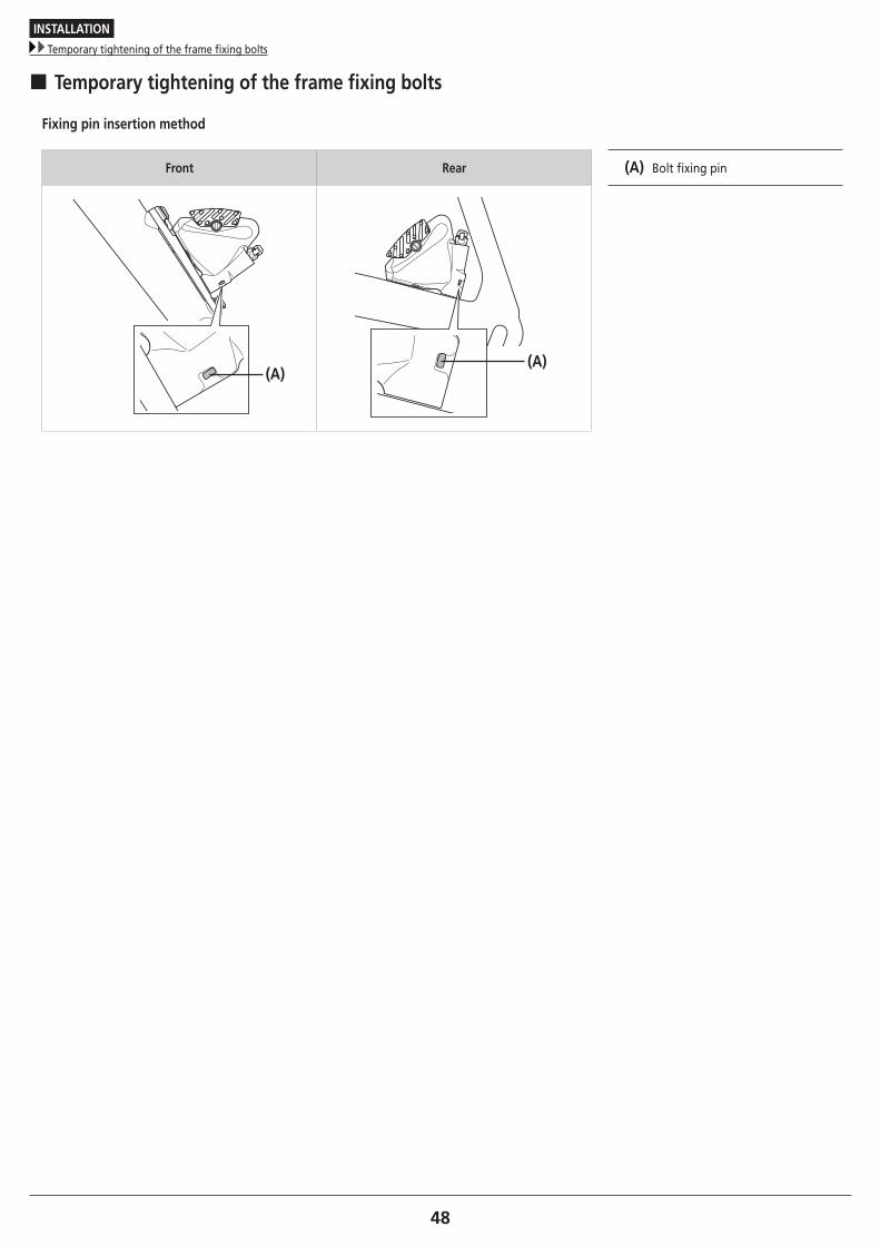
� Temporary tightening of the frame fixing bolts
Fixing pin insertion method
Front Rear
(A)(A)
(A) Bolt fixing pin
INSTALLATION
Installation of the shifting cable
49
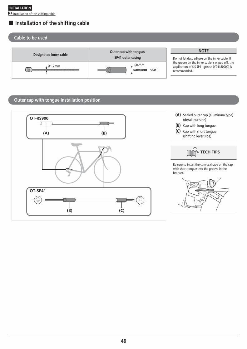
� Installation of the shifting cable
Cable to be used
Designated inner cableOuter cap with tongue/
SP41 outer casing
Ø1.2mmSP41
Ø4mm
NOTE
Do not let dust adhere on the inner cable. If the grease on the inner cable is wiped off, the application of SIS SP41 grease (Y04180000) is recommended.
Outer cap with tongue installation position
(A) (B)
(B) (C)
OT-RS900
OT-SP41
(A) Sealed outer cap (aluminum type) (derailleur side)
(B) Cap with long tongue
(C) Cap with short tongue (shifting lever side)
TECH TIPS
Be sure to insert the convex shape on the cap with short tongue into the groove in the bracket.
INSTALLATION
Installation of the shifting cable
50
Cutting the outer casing
1
SP41
(B)
(A)
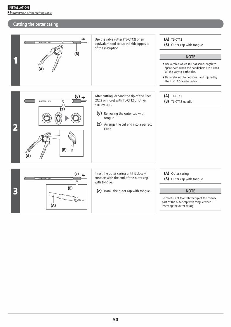
Use the cable cutter (TL-CT12) or an equivalent tool to cut the side opposite of the inscription.
(A) TL-CT12
(B) Outer cap with tongue
NOTE
• Use a cable which still has some length to spare even when the handlebars are turned all the way to both sides.
• Be careful not to get your hand injured by the TL-CT12 needle section.
2
SP41
(z)
(y)
(B)(A)
After cutting, expand the tip of the liner (Ø2.2 or more) with TL-CT12 or other narrow tool.
(y) Removing the outer cap with tongue
(z) Arrange the cut end into a perfect circle
(A) TL-CT12
(B) TL-CT12 needle
3
SP41
(B)
(z)
(A)
Insert the outer casing until it closely contacts with the end of the outer cap with tongue.
(z) Install the outer cap with tongue
(A) Outer casing
(B) Outer cap with tongue
NOTE
Be careful not to crush the tip of the convex part of the outer cap with tongue when inserting the outer casing.
INSTALLATION
Installation of the shifting cable
51To be continued on next page
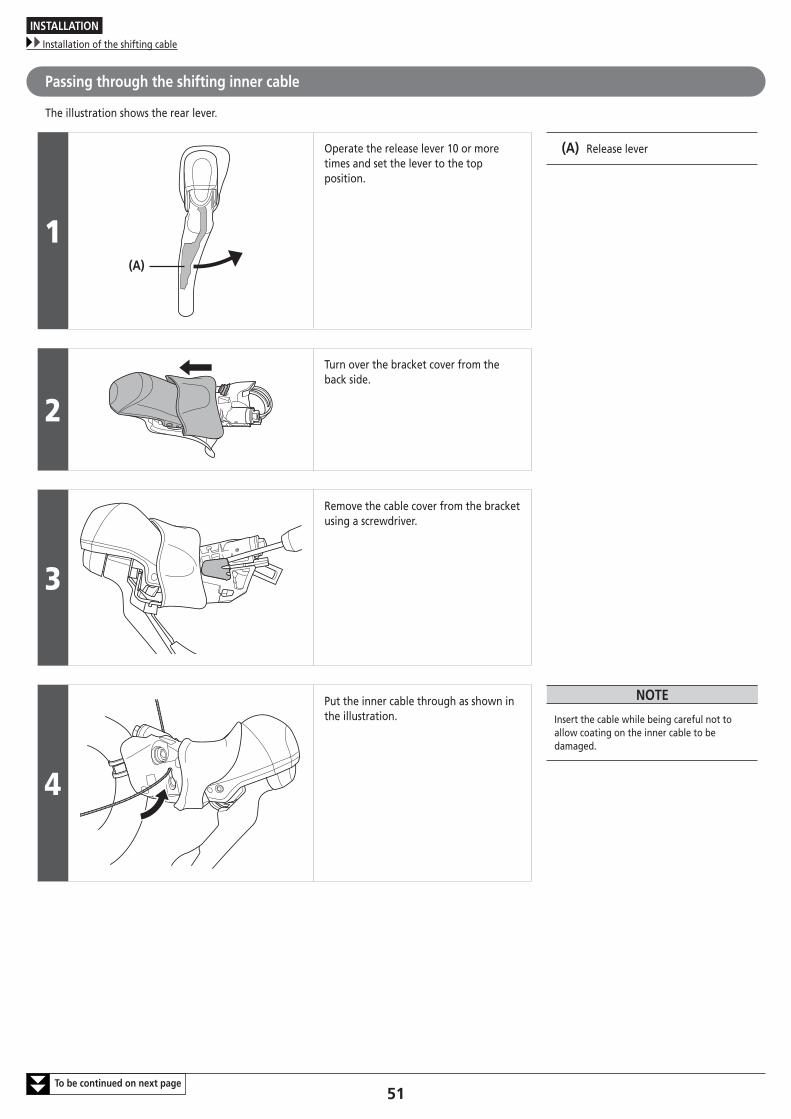
Passing through the shifting inner cable
The illustration shows the rear lever.
1(A)
Operate the release lever 10 or more times and set the lever to the top position.
(A) Release lever
2
Turn over the bracket cover from the back side.
3
Remove the cable cover from the bracket using a screwdriver.
4
Put the inner cable through as shown in the illustration.
NOTE
Insert the cable while being careful not to allow coating on the inner cable to be damaged.
INSTALLATION
Installation of the shifting cable
52
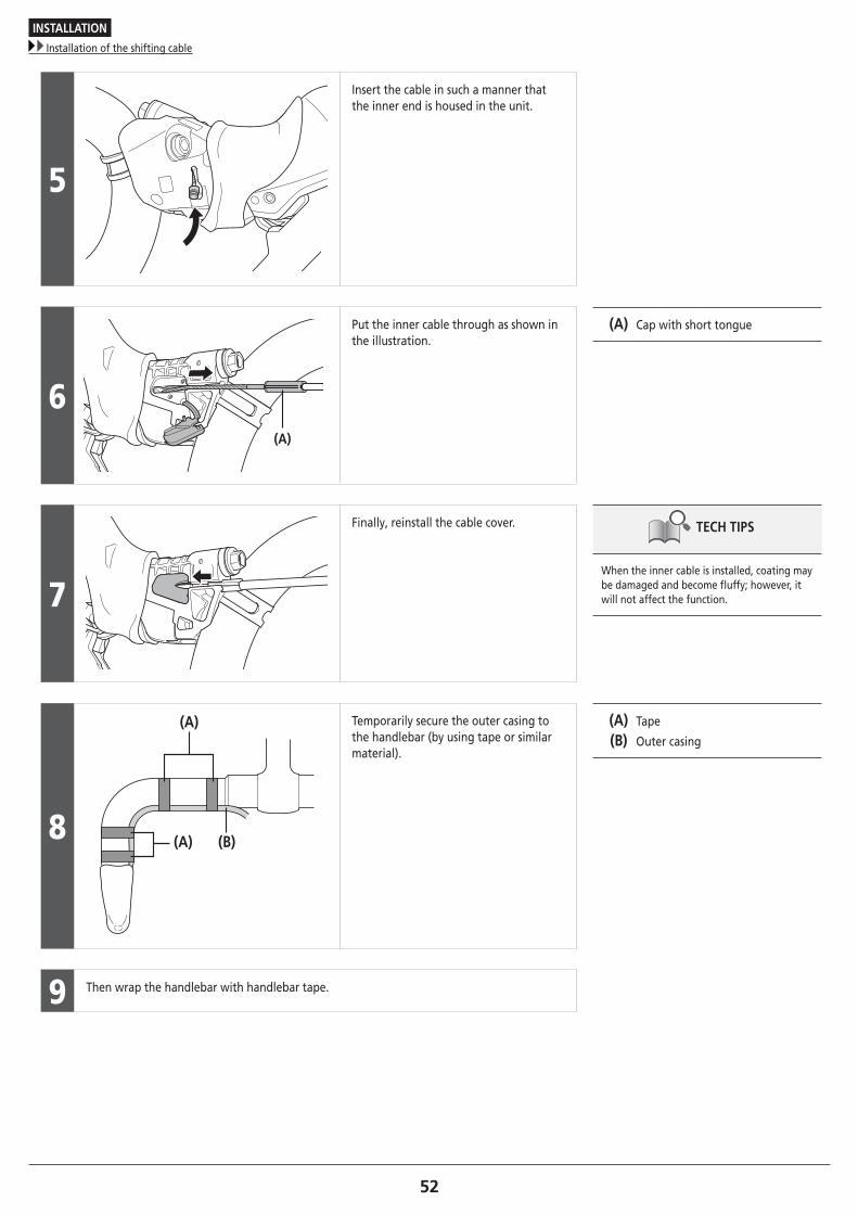
5
Insert the cable in such a manner that the inner end is housed in the unit.
6(A)
Put the inner cable through as shown in the illustration.
(A) Cap with short tongue
7
Finally, reinstall the cable cover. TECH TIPS
When the inner cable is installed, coating may be damaged and become fluffy; however, it will not affect the function.
8 (B)(A)
(A) Temporarily secure the outer casing to the handlebar (by using tape or similar material).
(A) Tape
(B) Outer casing
9 Then wrap the handlebar with handlebar tape.

ADJUSTMENT
ADJUSTMENT
Free stroke and reach adjustment
54To be continued on next page
ADJUSTMENT
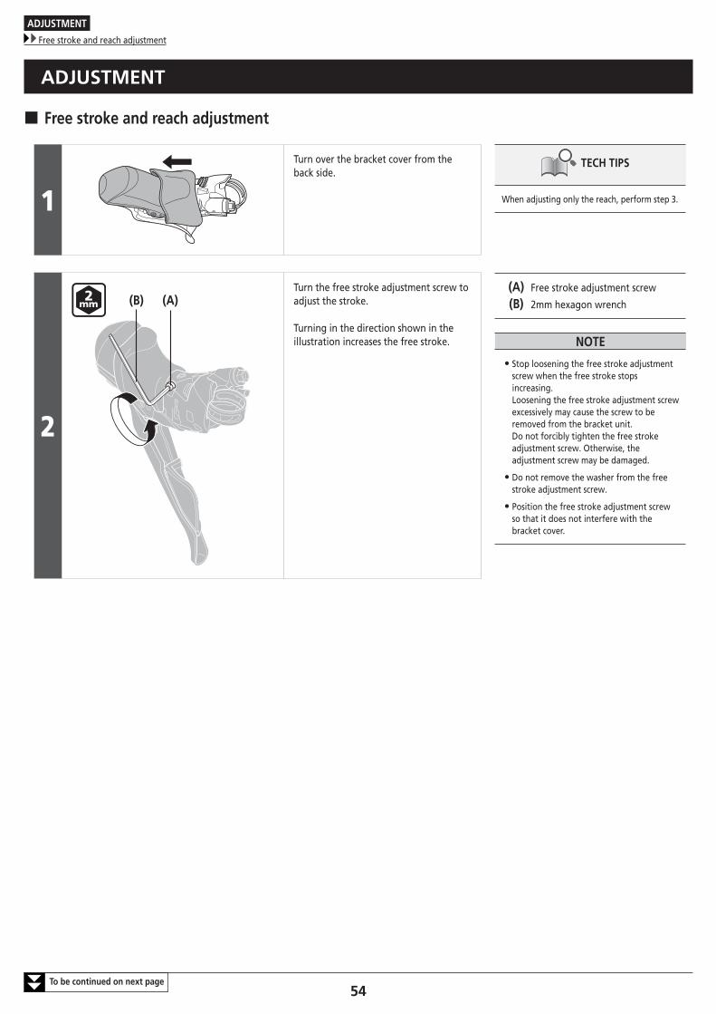
� Free stroke and reach adjustment
1
Turn over the bracket cover from the back side.
TECH TIPS
When adjusting only the reach, perform step 3.
2
(A)(B)Turn the free stroke adjustment screw to adjust the stroke.
Turning in the direction shown in the illustration increases the free stroke.
(A) Free stroke adjustment screw
(B) 2mm hexagon wrench
NOTE
• Stop loosening the free stroke adjustment screw when the free stroke stops increasing. Loosening the free stroke adjustment screw excessively may cause the screw to be removed from the bracket unit. Do not forcibly tighten the free stroke adjustment screw. Otherwise, the adjustment screw may be damaged.
• Do not remove the washer from the free stroke adjustment screw.
• Position the free stroke adjustment screw so that it does not interfere with the bracket cover.
ADJUSTMENT
Free stroke and reach adjustment
55
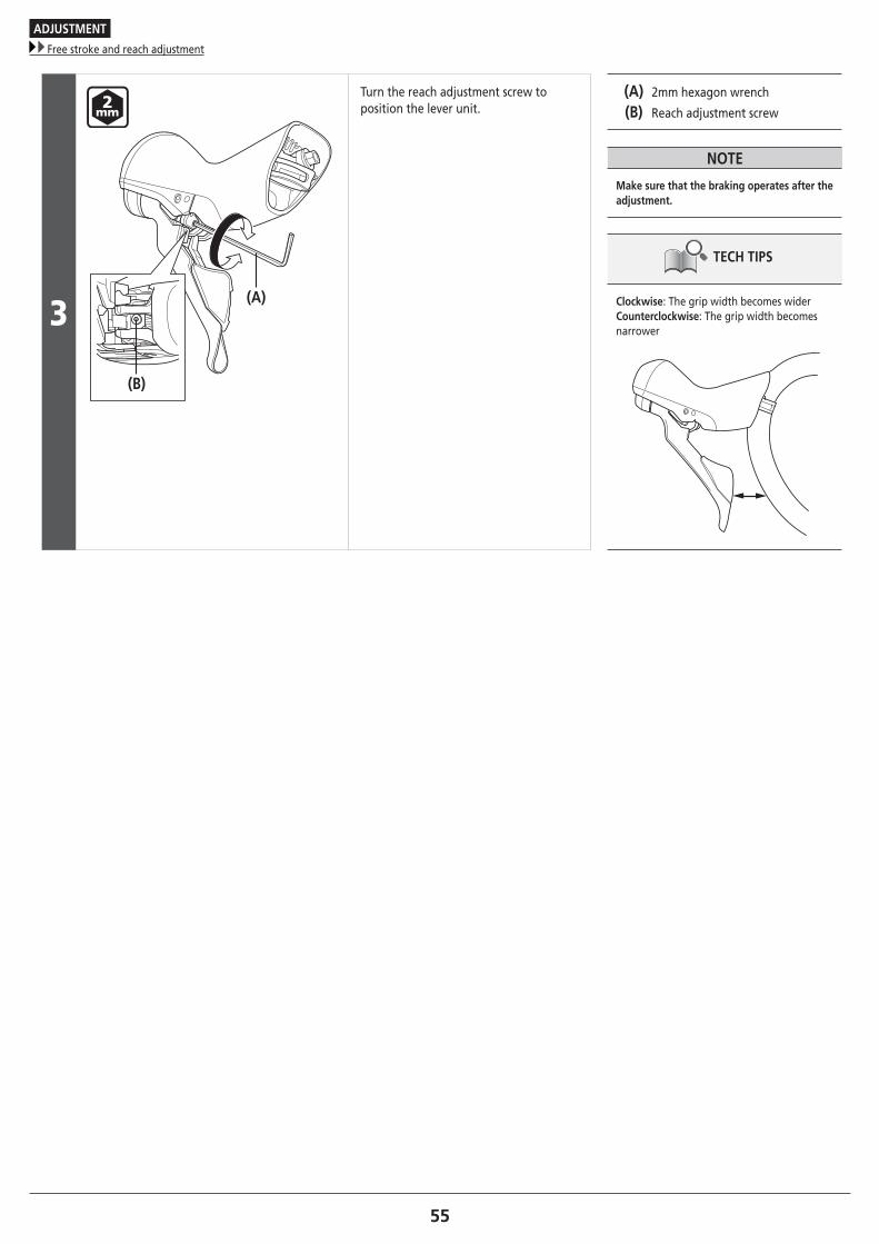
3
(B)
(A)
Turn the reach adjustment screw to position the lever unit.
(A) 2mm hexagon wrench
(B) Reach adjustment screw
NOTE
Make sure that the braking operates after the adjustment.
TECH TIPS
Clockwise: The grip width becomes widerCounterclockwise: The grip width becomes narrower
MAINTENANCE
MAINTENANCE
Replacing the brake pads
57To be continued on next page
MAINTENANCE
� Replacing the brake pads
1(B)
(A)
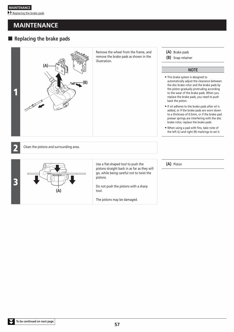
Remove the wheel from the frame, and remove the brake pads as shown in the illustration.
(A) Brake pads
(B) Snap retainer
NOTE
• This brake system is designed to automatically adjust the clearance between the disc brake rotor and the brake pads by the piston gradually protruding according to the wear of the brake pads. When you replace the brake pads, you need to push back the piston.
• If oil adheres to the brake pads after oil is added, or if the brake pads are worn down to a thickness of 0.5mm, or if the brake pad presser springs are interfering with the disc brake rotor, replace the brake pads.
• When using a pad with fins, take note of the left (L) and right (R) markings to set it.
2 Clean the pistons and surrounding area.
3(A)
Use a flat-shaped tool to push the pistons straight back in as far as they will go, while being careful not to twist the pistons.
Do not push the pistons with a sharp tool.
The pistons may be damaged.
(A) Piston
MAINTENANCE
Replacing the brake pads
58
4
(A)
(B)
(C)
(D)
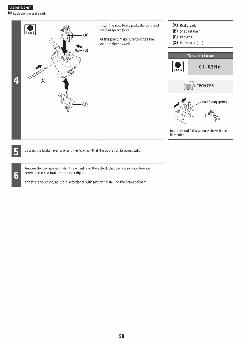
Install the new brake pads, the bolt, and the pad spacer (red).
At this point, make sure to install the snap retainer as well.
(A) Brake pads
(B) Snap retainer
(C) Pad axle
(D) Pad spacer (red)
Tightening torque
0.1 - 0.3 N·m
TECH TIPS
Pad fixing spring
Install the pad fixing spring as shown in the illustration.
5 Depress the brake lever several times to check that the operation becomes stiff.
6Remove the pad spacer, install the wheel, and then check that there is no interference between the disc brake rotor and caliper.
If they are touching, adjust in accordance with section "Installing the brake caliper".
MAINTENANCE
Replacement of the nameplate
59
� Replacement of the nameplate
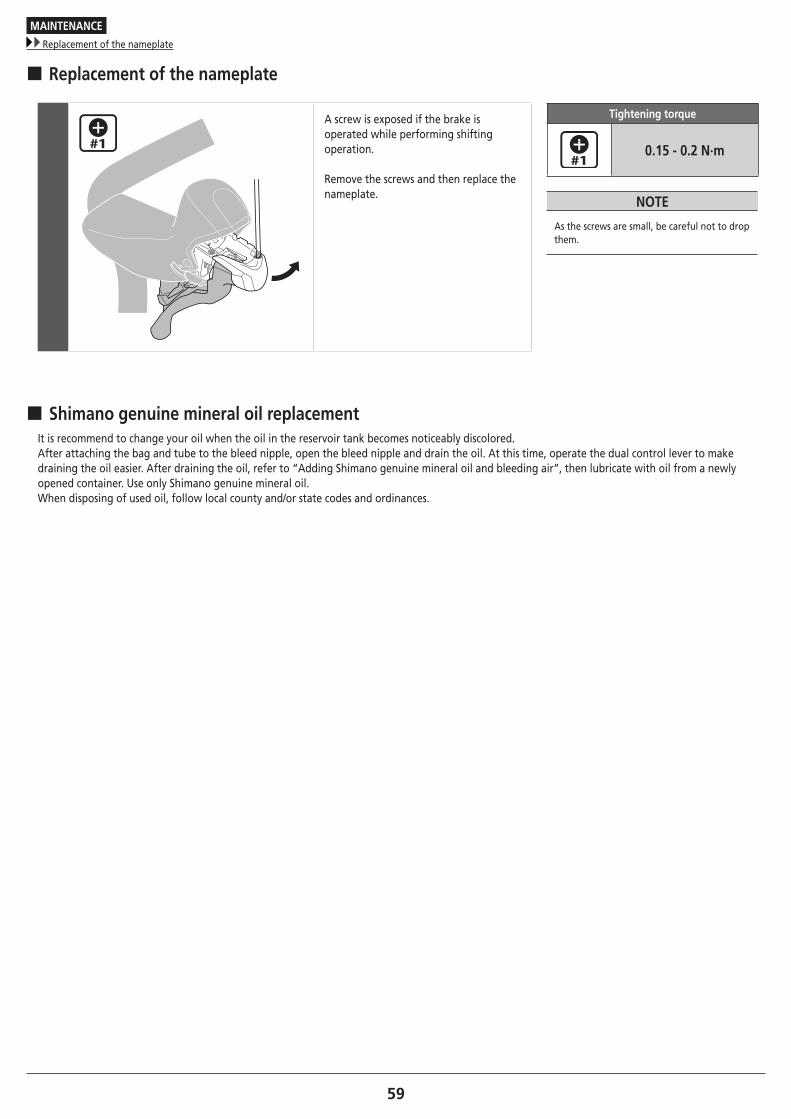
A screw is exposed if the brake is operated while performing shifting operation.
Remove the screws and then replace the nameplate.
Tightening torque
0.15 - 0.2 N·m
NOTE
As the screws are small, be careful not to drop them.
� Shimano genuine mineral oil replacementIt is recommend to change your oil when the oil in the reservoir tank becomes noticeably discolored.After attaching the bag and tube to the bleed nipple, open the bleed nipple and drain the oil. At this time, operate the dual control lever to make draining the oil easier. After draining the oil, refer to “Adding Shimano genuine mineral oil and bleeding air”, then lubricate with oil from a newly opened container. Use only Shimano genuine mineral oil.When disposing of used oil, follow local county and/or state codes and ordinances.
MAINTENANCE
Replacing the bracket cover
60
� Replacing the bracket cover
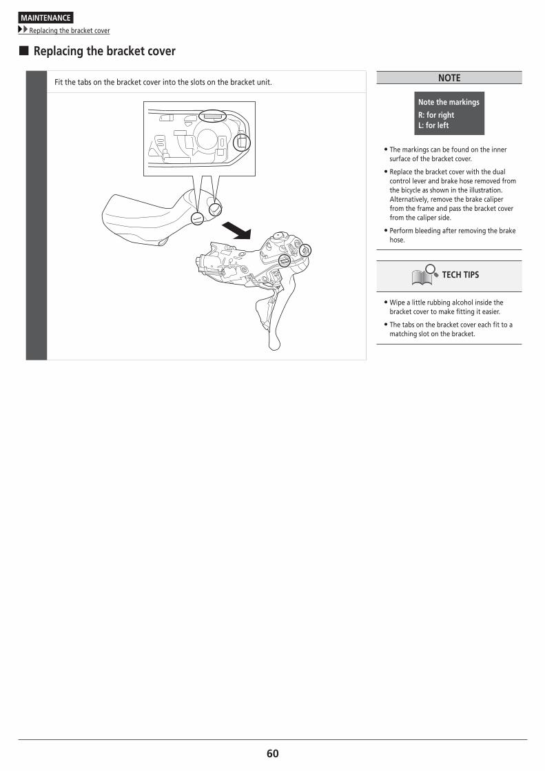
Fit the tabs on the bracket cover into the slots on the bracket unit. NOTE
Note the markings
R: for right L: for left
• The markings can be found on the inner surface of the bracket cover.
• Replace the bracket cover with the dual control lever and brake hose removed from the bicycle as shown in the illustration. Alternatively, remove the brake caliper from the frame and pass the bracket cover from the caliper side.
• Perform bleeding after removing the brake hose.
TECH TIPS
• Wipe a little rubbing alcohol inside the bracket cover to make fitting it easier.
• The tabs on the bracket cover each fit to a matching slot on the bracket.
MAINTENANCE
Replacing the main lever support
61To be continued on next page
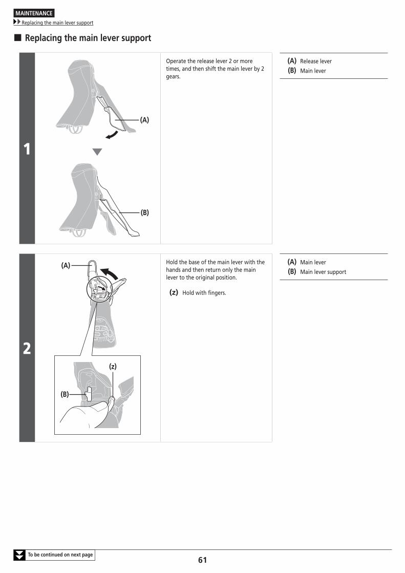
� Replacing the main lever support
1
(B)
(A)
Operate the release lever 2 or more times, and then shift the main lever by 2 gears.
(A) Release lever
(B) Main lever
2
(A)
(B)
(z)
Hold the base of the main lever with the hands and then return only the main lever to the original position.
(z) Hold with fingers.
(A) Main lever
(B) Main lever support
MAINTENANCE
Replacing the main lever support
62
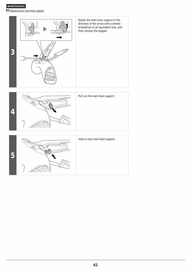
3
Rotate the main lever support in the direction of the arrow with a slotted screwdriver or an equivalent tool, and then remove the stopper.
4
Pull out the main lever support.
5
Insert a new main lever support.
MAINTENANCE
Replacing the cable cover
63
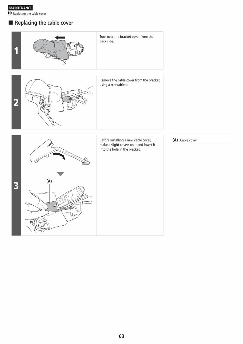
� Replacing the cable cover
1
Turn over the bracket cover from the back side.
2
Remove the cable cover from the bracket using a screwdriver.
3(A)
Before installing a new cable cover, make a slight crease on it and insert it into the hole in the bracket.
(A) Cable cover
MAINTENANCE
How to pull out a disconnected inner end (shifting cable)
64
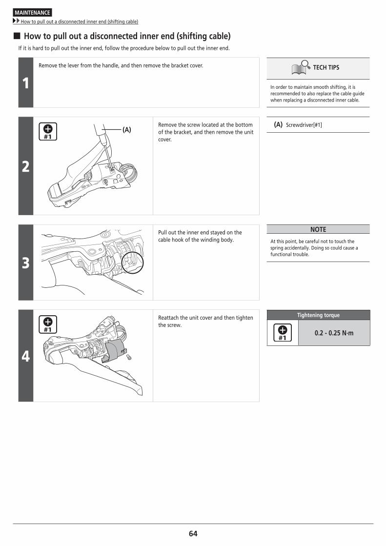
� How to pull out a disconnected inner end (shifting cable)If it is hard to pull out the inner end, follow the procedure below to pull out the inner end.
1Remove the lever from the handle, and then remove the bracket cover. TECH TIPS
In order to maintain smooth shifting, it is recommended to also replace the cable guide when replacing a disconnected inner cable.
2
(A)Remove the screw located at the bottom of the bracket, and then remove the unit cover.
(A) Screwdriver[#1]
3
Pull out the inner end stayed on the cable hook of the winding body.
NOTE
At this point, be careful not to touch the spring accidentally. Doing so could cause a functional trouble.
4
Reattach the unit cover and then tighten the screw.
Tightening torque
0.2 - 0.25 N·m
MAINTENANCE
Replacement of the SL cable guide
65
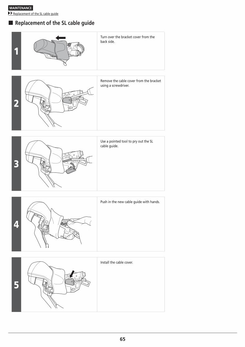
� Replacement of the SL cable guide
1
Turn over the bracket cover from the back side.
2
Remove the cable cover from the bracket using a screwdriver.
3
Use a pointed tool to pry out the SL cable guide.
4
Push in the new cable guide with hands.
5
Install the cable cover.

Please note: specifications are subject to change for improvement without notice. (English) © Dec. 2016 by Shimano Inc. HTR