Embed Size (px)
Citation preview

Max. Lifting Capacity: 55 t x 3.7 mMax. Crane Boom Length: 51.8 mMax. Fixed Jib Combination: 42.7 + 12.2 m, 39.6 + 18.3 mMax. Tower Jib Combination: 42.4 + 29.0 m
HYDRAULIC CRAWLER CRANE
Model: 7055-3F

1
CONFIGURATION
Crane BoomMax. Lifting Capacity:
55 metric ton x 3.7 mMax. Boom Length:
51.8 m
Fixed JibMax. Lifting Capacity:
7 metric ton x 16.0 mMax. Combination:
42.7 m + 12.2 m, 39.6 m + 18.3 m

2
CONTENTS
Configuration ··················· 1
Specifications ···················· 3
General Dimensions ········· 5
Boom andJib Arrangements
Crane Boom Arrangements ················· 7
Fixed Jib Arrangements ················· 7
Tower Arrangements ················· 8
Tower Jib Arrangements ················· 8
Working Ranges and Lifting Capacities
Crane Boom Working Ranges ··········· 10
Crane Boom Lifting Capacity ············ 11
Auxiliary Sheave Lifting Capacityfor Crane Boom ·················· 11
Fixed Jib Working Ranges ··········· 12
Fixed Jib Lifting Capacities ········· 13
Tower JibWorking Ranges ··········· 15
Tower JibLifting Capacities ········· 17
Parts and Attachments ··· 21
Tower JibMax. Lifting Capacity:
12 metric ton x 10.0 mMax. Combination:
42.4 m + 29.0 m

SPECIFICATIONS
3
Model:Hino diesel engine J08E-TMType:Water-cooled, direct fuel injection, with turbochargerCompiles with NRMM (Europe) Stage IIIA and US EPA Tier III.Displacement: 7.684 liters Rated Power: 159 kW at 2,000 min-1 {rpm} (ISO)Max. torque: 797 N•m/1,600 min-1
Cooling system: Liquid, recirculating bypassStarter: 24 V/5.0 kWRadiator: Corrugated type core, thermostatically controlledAir cleaner: Dry type with replaceable paper elementThrottle: Electric throttle control, twist grip typeFuel filter: Replaceable paper elementBatteries: Two 12 V,136Ah/5HR capacity batteries, series con-nected.Fuel tank capacity: 400 liters
Three variable displacement piston pumps are driven by heavy-duty pump drive. Two of variable displacement pumps are usedin the main hook hoist circuit, boom hoist circuit, auxiliary hookhoist circuit, third hoist circuit and each propel circuit. The otheris used in the swing circuit.
Control: Full-flow hydraulic control system for infinitely variablepressure to front and rear drums, boom hoist brakes andclutches. Controls respond instantly to the touch, deliveringsmooth function operation.
Cooling: Oil-to-air heat exchanger (plate-fin type)Filtration: Full-flow and bypass type with replaceable elementElectrical system: All wiring corded for easy servicing, individ-ual fused branch circuits.
Max. relief valve pressure:Load hoist, boom hoist and propel system: 31.9 MPa {325 kgf/cm2}Swing system: 27.5 MPa {280 kgf/cm2}Control system: 7.0 MPa {71 kgf/cm2}
Reservoir capacity: 440 liters
Powered by a hydraulic motor through a planetary reducer.Brake: A spring-set, hydraulically released multiple-disc brakeis mounted on the boom hoist motor and operated through acounter-balance valve.
Drum lock: External ratchet for locking drum.Drum: Single drum, grooved for 16 mm dia. wire rope.Line speed: Single line on first drum layer
Hoisting/Lowering: 70 to 2 m/min
Diameter of wire ropesBoom guy line: 30 mmBoom hoist reeving: 12 parts of 16 mm dia.high strengthwire rope
Boom backstops: Telescopic type with spring bumperRequired for all boom lengths
Front and rear drums for load hoist powered by a hydraulic variable plunger motors, driven through planetary reducers.
Brake: A spring-set, hydraulically released multiple-disc brakeis mounted on the hoist motor and operated through a counter-balance valve. Both positive and negative brake systems areavailable.
Drum lock: External ratchet for locking drum.Drums:
Front drum: 550 mm P.C.D. x 545 mm Lg. wide drum, grooved for 22 mm wire rope. Rope capacity is 175 m working length and 335 m storage length.
Rear drum:550 mm P.C.D. x 545 mm Lg. wide drum, grooved for 22 mm wire rope. Rope capacity is 125 m working length and 335 m storage length.Note: Rope lengths listed above denote drum capacity and may differ from actual rope lengths supplied when machinery is shipped.
Line speed: Single line on the first drum layerHoisting/Lowering: 120 to 3 m/minTower Jib Hoisting/Lowering: 90 to 3 m/min(Rear drum)
Line Pull:Rated line pull (Single-line): 68.6 kN {7.0 tf}
Swing unit is powered by hydraulic motor driving spur gearthrough planetary reducer, the swing system provides 360°rotation.
Swing parking brakes: A spring-set, hydraulically releasedmultiple-disc brake is mounted on swing motor.Swing circle: Single-row ball bearing with an integral internallycut swing gear.Swing lock: Manually, two position lock for transportationSwing speed: 4.0 min-1 {rpm}
Torsion-free precision machined upper frame. All componentsare located clearly and service friendly. Engine with low noiselevel.
Counterweight: 15.2 tonAdditional counterweight: 3.3 tonNote: Additional counterweight is required when raising or lowering the tower length of42.4 m.
Power Plant
Load Hoist System
Hydraulic System
Boom Hoisting System
Swing System
Upper Structure

Totally enclosed, full vision cab with safety glass, fullyadjustable, high backed seat with a head-rest and armrests,and intermittent wiper and window washer (skylight and frontwindow).
Cab fittings:Air conditioner, convenient compartment (for tool), cup holder,ashtray, cigarette lighter, sun visor, roof blind, tinted glass, floormat, foot-rest, shoe tray
Controls:Four adjustable levers for front drum, rear drum, boom drum andswing controls
Steel-welded carbody with axles. Crawler assemblies can behydraulically extended for wide-track operation or retracted fortransportation. Crawler belt tension is maintained by hydraulicjack force on the track-adjusting bearing block.
Crawler drive: Independent hydraulic propel drive is built intoeach crawler side frame. Each drive consists of a hydraulicmotor propelling a driving tumbler through a planetary gearbox. Hydraulic motor and gear box are built into the crawlerside frame within the shoe width.
Crawler brakes: Spring-set, hydraulically released parkingbrakes are built into each propel drive.Steering mechanism: A hydraulic propel system provides bothskid steering (driving one track only) and counter-rotating steer-ing (driving each track in opposite directions).
Track rollers: Sealed track rollers for maintenance-free opera-tion.
4
Lower Structure
Shoes (flat): 59 shoes, 760 mm wide each crawlerMax. travel speed: 2.4/1.5 km/hMax. gradeability: 40%
Including upper and lower machine, 15.2 ton counterweight,basic boom (or basic tower + basic tower jib), hook, and otheraccessories.
Specification Weight Ground pressureCrane boom Approx. 56.7 ton, 72.3 kPa {0.74 kgf/cm2}Tower jib Approx. 60.6 ton, 77.3 kPa {0.79 kgf/cm2}
Boom and Jib:Welded lattice construction using tubular, high-tensile steelchords with pin connections between sections.
Boom and Jib Length
Min. Length Max. Length(Min. Combination) (Max. Combination)
Crane Boom 9.1 m 51.8 m
Fixed Jib 30.5 m + 6.1 m 42.7 m + 12.2 m39.6 m + 18.3 m
Tower Jib 21.0 m + 16.8 m 42.4 m + 29.0 m
Weight
Attachment
Main Specifications (Model: 7055-3F)Crane BoomMax. Lifting Capacity 55 t/3.7 mMax. Length 51.8 mFixed JibMax. Lifting Capacity 7 t/16.0 mMax. Combination 42.7 m + 12.2 m, 39.6 m + 18.3 mTower JibMax. Lifting Capacity 12 t/10.0 mMax. Combination 42.4 m + 29.0 mTower Angle 60˚ ~ 90˚Main & Aux. WinchMax. Line Speed 120 m/min (1st layer)Rated Line Pull (Single Line) 68.6 kN {7.0 tf}Wire Rope Diameter 22 mm
Wire Rope LengthCrane 175 m (Main) 125 m (Aux.) Tower 220 m (Main) 120 m (Aux.)
Brake Type Spring-set hydraulically releasedWorking SpeedSwing Speed 4.0 min-1 {rpm}Travel Speed 2.4/1.5 km/h
Power PlantModel Hino J08E-TMEngine Output 159 kW/2,000 min-1 {rpm}Fuel Tank Capacity 400 litersHydraulic SystemMain Pumps 3 variable displacementMax. Pressure 31.9 MPa {325 kgf/cm2}Hydraulic Tank Capacity 440 litersWeightOperating Weight* Approx. 56.7 tGround Pressure* 72.3 kPa {0.74 kgf/cm2}Counterweight 15.2 tTransport Weight** 40.2 t
* Including upper and lower machine, 15.2 ton counterweight, basic boom, hook,and other accessories.
** Base machine with boom base, crawlers, gantry, lower spreader, upper spread-er, wire ropes for main and boom hoist winches.
Units are SI units. {} indicates conventional units.
Cab & Control

5
GENERAL DIMENSIONS
5,235
R 3,800
1,100
3,30
0
6,18
0
1,10
0
2,87
5
4,720
5,570
1,75
0
3,18
0Cran
e Boo
m Leng
th: 9.
1m~
51.8m
940
760
1,600
3,200
3,200 (Retracted)
4,530 (Extended)
380
Crane Boom
Limit of Hook Lifting
L L'Hook L
55 t hook 3.9 m
32 t hook 3.7 m
19 t hook 3.6 m
Hook L'
7 t �
ball hook3.0 m
(Unit: mm)

15˚- 75˚Jib offset Angle is Limited (OVER 15˚)
Tower Jib Length: 16.8m~29.0m
Tow
er L
engt
h: 2
1.0m
- 4
2.4m
Tower Angle (60˚- 90˚)
1,75
0
1,100
6
Tower Jib (Unit: mm)

7
Boom length m (ft) Boom arrangement
mark shows the guy line installing position when the fixed jib is used.
mark shows the standard boom arrangement which enables each boom length of less than that boom length to be configured.
TB5.2 3.9
TB 10
TB 20
TB 10 10
TB 30
TB 2010
TB 3010
TB 201010
TB 2020
TB 3020
TB 10 10 30
TB 202010
TB 2010 30
TB 3030
TB 20201010
TB 20A20 30
TB 20A10 10 30
TB 10 3030A
9.1 (30)
12.2 (40)
15.2 (50)
18.3 (60)
21.3 (70)
24.4 (80)
27.4 (90)
30.5 (100)Symbol Boom Length
5.2 m3.9 m3.0 m6.1 m6.1 m9.1 m9.1 m
RemarksBoom BaseBoom Top
Insert BoomInsert Boom
Insert Boom with LugInsert Boom
Insert Boom with Lug
T
B
20
20A
10
30
30A
Boom length m (ft) Boom arrangement
TB 20A2010 30
33.5 (110)
36.6 (120)
39.6 (130)
42.7 (140)
45.7 (150)
48.8 (160)
51.8 (170)
TB 20 3030A
TB 10 10 3030A
TB 20A201010 30
TB 3030A30
TB 2020 3030A
TB 201010 3030A
TB 20 20 20A 3010
TB 20 20 20 3030A
TB 202010 10 3030A
TB 30A202010 30
TB 20A202010 10 30
TB 20 20 2010 3030A
TB 2020201010 3030A
TB 2010 3030A
Note:In the following cases a 6.1 m or 9.1 m insert boom with lug is required:1. With a fixed jib fitted2. When assembling a boom length of 39.6 m or over without using an auxiliary crane
Crane Boom Arrangements
BOOM AND JIB ARRANGEMENTS
Fixed Jib
Jib arrangement
30.5 m
42.7 m
Jib length m (ft)
6.1(20)
12.2 (40)
18.3 (60)
B T20
B T20 20
T
B T3.0 3.0
20
B
Symbol Jib Length3.0 m3.0 m6.1 m
RemarksJib BaseJib Top
Insert Jib
Craneboomlength
~
30.5 m
39.6 m
~ Insert Boom with Lug
Boom
Jib Guy Line: 20 mm
Fixed Jib Arrangements

8
10
10
10 20
20
20 30
30
30B
30B
10 10 20 3030B
20 20 3030B
21.0 (69)
24.1 (79)
27.1 (89)
30.2 (99)
33.2 (109)
36.3 (119)
39.3 (129)
42.4 (139)
Jib length m (ft) Jib arrangement
16.8 (55)
19.8 (65)
22.9 (75)
25.9 (85)
29.0 (95)
mark shows the standard tower arrangement which enables each tower length of less than that tower length to be configured.
Symbol Tower Length5.2 m0.6 m3.0 m6.1 m9.1 m9.1 m
RemarksBoom BaseTower Cap
Insert BoomInsert BoomInsert Boom
Special Insert Boom for Tower
30B 10 20
10 10 20
30B
30B 30
10 20
20
20
20 2030B
30B
TB
TB
T
T
T
T
T
T
T
T
T
B
B
B
B
B
B
B
10
20
mark shows the standard tower jib arrangement which enables each tower jib length of less than that jib length to be configured.
Symbol Tower Jib Length4.6 m3.1 m3.0 m6.1 m
RemarksTower Jib BaseTower Jib Top
Tower Insert JibTower Insert Jib
B
B
B
TB
30B
5.2
20
0.6
TB
10 10 20 2030B
10 20 3030B
10 20 20 3030B
10 T
T
B
B
TB
T
T
T
B
B
20
4.6 3.1
10 10 20
20 20
10 20 20
10 20 20 20
TB 2020 20
TB 10 10 20 20
Tower length m (ft) Tower arrangement
mark indicates the cable roller install position.
Tower Arrangements Tower Jib Arrangements
Jib lengthTower length
Jib
Poin
tW
eigh
tH
ook
○ ×
Need ×
16.8 m
○ ○ ×
Need
19.8 m
- ○ ○ × ×
22.9 m
- ○ ○ × ×
25.9 m
--- ○ ○ × ×
29.0 m
------
NeedNeed
Pillowplate
Add.weight*
21.0 m 24.1 m 27.1 m 30.2 m 33.2 m 36.3 m 39.3 m 42.4 m 19 ton hookBall hook
19 ton hookBall hook
90°-60° 90°-60° 90°-60° 90°-60° 90°-60° 90°-60° 90°-70° 90°-70°
90°-60° 90°-60° 90°-60° 90°-60° 90°-60° 90°-70° 90°-70° 90°-70°
90°-60° 90°-60° 90°-60° 90°-70° 90°-70° 90°-70° 90°-70°
- 90°-60° 90°-60° 90°-70° 90°-70° 90°-70° 90°-70°
90°-70° 90°-70° 90°-70° 90°-70° 90°-75°
*Add. weight: Additional weight for self-erection
×××××××
Need
○ : Available × : Not available
Tower and Jib Combinations and Allowable Tower Angle

Symbols for Attachments:
Crane BoomAuxiliary Sheavefor Crane Boom Fixed Jib Tower Jib
9
A range of hook blocks can be specified, each with a safety latch.
Hook Blocks
No. of lines and max. rated loads (tons)Hooks Weight (kg) No. of
1 2 3 4 5 6 7 8sheaves
55-ton 650 5 - - 21.0 28.0 35.0 42.0 49.0 55.032-ton 500 2 - - 21.0 28.0 32.0 - - -19-ton 400 1 - 14.0 19.0 - - - - -7-ton 160 0 7.0ball hook
- - - - - - -

10
WORKING RANGESAND LIFTING CAPACITIES
Hei
gh
t ab
ove
gro
un
d (
m)
Center of rotation
Radius from center of rotation (m)
1.75
m
1.1 m
51.8 m BOOM
12.2 m BOOM
15.2 m BOOM
18.3 m BOOM
21.3 m BOOM
24.4 m BOOM
27.4 m BOOM
30.5 m BOOM
33.5 m BOOM
36.6 m BOOM
39.6 m BOOM
42.7 m BOOM
45.7 m BOOM
48.8 m BOOM
9.1 m BOOM
75゚ 70゚ 65゚ 60゚ 55゚80゚
403020102 44
50
40
30
20
60
50゚
45゚
40゚
35゚
30゚
Crane Boom Working Ranges
NOTES:1. Ratings according to Japanese Construction Codes for Mobile Cranes
and Japanese Safety Ordinance on Cranes, etc.2. Ratings in metric tons for 360° working area.3. Operating radius is the horizontal distance from center of rotation to a
vertical line through the center of gravity of the load.4. Weight of hook block(s), slings and other load handling accessories is
included in rated load. Their total weight must be subtracted from ratedload to obtain weight that can be lifted.
5. Ratings shown are based on freely suspended loads and make noallowance for such factors as wind effect on lifted load, ground condi-tions out-of-level, operating speeds or any other condition that could bedetrimental to the safe operation of this equipment. Operator, therefore,has the responsibility to judge the existing conditions and reduce liftedloads and operating speeds accordingly.
6. Ratings are for operation on a firm and level surface.7. At radii and boom lengths where no ratings are shown on chart, opera-
tion is not intended nor approved.
8. Boom inserts and guy lines must be arranged as shown in the“Operator's Manual”.
9. Boom hoist reeving is 12 part line.10. Gantry must be in raised position for all conditions.11. Boom backstops are required for all boom lengths.12. Crawler frames must be fully extended for all crane operations.13. Ratings shown in are determined by the strength of the boom
or other structural component.14. Instruction in the “Operator's Manual” must be strictly observed when
operating the machine.15. Crane boom ratings: Deduct weight of main hook block, slings, and all
other load handling accessories from crane boom ratings shown.16. Auxiliary sheave ratings for crane boom: Deduct weight of ball hook,
slings, and all other load handling accessories from auxiliary sheave rat-ings for crane boom shown.
17. Crane boom lengths for auxiliary sheave mounting are 9.1 m to 48.8 m.18. Crane boom ratings with auxiliary sheave: Deduct 0.5 ton from crane
boom ratings shown. Minimum rated loads must exceed 1.1 ton.
Unit: metric ton
11
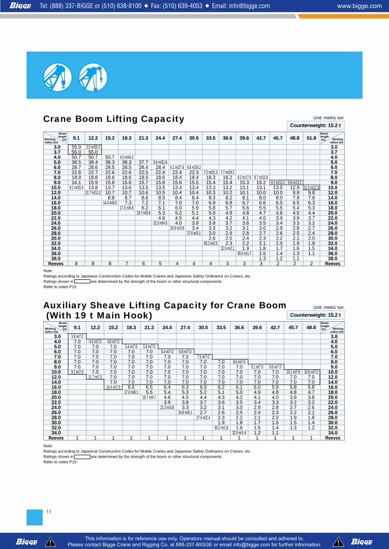
Crane Boom Lifting CapacityBoomlength
(m)Workingradius (m)
55.055.050.738.528.722.818.916.1
9.1 m/15.9
8
9.1
3.5 m/55.055.050.738.428.622.718.815.913.8
11.7 m/11.2
8
12.2
50.738.328.522.618.615.813.710.7 8.8
14.4 m/8.5
8
15.2
4.5 m/44.338.328.522.618.615.813.610.7 8.7 7.3
17.0 m/6.8
7
18.3
37.728.422.518.515.713.510.6 8.6 7.2 6.2
19.7 m/5.4
6
21.3
5.6 m/31.628.422.418.515.613.510.5 8.5 7.1 6.1 5.3 4.6
22.3 m/4.5
5
24.4
6.1 m/27.622.418.415.613.410.4 8.4 7.0 6.0 5.2 4.5 4.0
24.9 m/3.8
4
27.4
6.6 m/24.222.318.415.513.410.4 8.4 7.0 5.9 5.1 4.4 3.9 3.4
27.6 m/3.1
4
30.5
7.2 m/21.318.315.413.310.3 8.3 6.9 5.8 5.0 4.3 3.8 3.3 3.0 2.6
30.2 m/2.5
4
33.5
7.7 m/19.218.215.413.210.2 8.2 6.8 5.7 4.9 4.2 3.7 3.2 2.9 2.5 2.3
32.9 m/2.1
3
36.6
8.2 m/17.415.313.110.1 8.1 6.7 5.6 4.8 4.1 3.6 3.1 2.8 2.4 2.2 1.9
35.5 m/1.7
3
39.6
8.7 m/15.815.213.110.0 8.0 6.6 5.5 4.7 4.0 3.5 3.0 2.7 2.3 2.1 1.8 1.5 1.3
3
42.7
9.3 m/13.213.010.0 8.0 6.5 5.5 4.6 3.9 3.4 2.9 2.6 2.2 2.0 1.7 1.4 1.2
2
45.7
9.8 m/13.212.9 9.9 7.9 6.5 5.4 4.5 3.9 3.3 2.8 2.5 2.1 1.9 1.6 1.3 1.1
2
48.8
10.3 m/11.89.87.86.35.34.43.73.22.72.42.01.81.51.1
2
51.8
3.0 3.7 4.0 5.0 6.0 7.0 8.0 9.010.012.014.016.018.020.022.024.026.028.030.032.034.036.038.0
Reeves
Boomlength (m) Working
radius (m)
3.0 3.7 4.0 5.0 6.0 7.0 8.0 9.010.012.014.016.018.020.022.024.026.028.030.032.034.036.038.0
Reeves
Unit: metric ton
Counterweight: 15.2 t
Counterweight: 15.2 t
Note: Ratings according to Japanese Construction Codes for Mobile Cranes and Japanese Safety Ordinance on Cranes, etc.Ratings shown in are determined by the strength of the boom or other structural components.Refer to notes P10.
Boomlength
(m)Workingradius (m)
3.8 m/7.07.07.07.07.07.07.0
9.1 m/7.0
1
9.1
4.3 m/7.07.07.07.07.07.07.0
11.7 m/7.0
1
12.2
4.8 m/7.07.07.07.07.07.07.07.07.0
14.4 m/7.0
1
15.2
5.4 m/7.07.07.07.07.07.07.07.06.6
17.0 m/6.1
1
18.3
5.9 m/7.07.07.07.07.07.07.07.06.55.5
19.7 m/4.7
1
21.3
6.4 m/7.07.07.07.07.07.07.06.45.44.63.9
22.3 m/3.8
1
24.4
6.9 m/7.07.07.07.07.07.07.06.35.34.53.83.3
24.9 m/3.1
1
27.4
7.5 m/7.07.07.07.07.07.06.35.24.43.73.22.7
27.6 m/2.4
1
30.5
7.07.07.07.07.06.25.14.33.63.12.62.31.9
30.2 m/1.8
1
33.5
8.5 m/7.07.07.07.07.06.15.04.23.53.02.52.21.81.6
32.9 m/1.41
36.6
9.1 m/7.07.07.07.06.04.94.13.42.92.42.11.71.51.21
39.6
9.6 m/7.07.07.07.05.94.84.03.32.82.32.01.61.41.11
42.7
10.1 m/7.07.07.05.84.83.93.22.72.21.91.51.3
1
45.7
10.6 m/7.07.07.05.84.73.83.22.62.11.81.41.2
1
48.8
3.0 4.0 5.0 6.0 7.0 8.0 9.010.012.014.016.018.020.022.024.026.028.030.032.034.0
Reeves
Boomlength (m) Working
radius (m)
3.8 4.0 5.0 6.0 7.0 8.0 9.010.012.014.016.018.020.022.024.026.028.030.032.034.0
Reeves
Note: Ratings according to Japanese Construction Codes for Mobile Cranes and Japanese Safety Ordinance on Cranes, etc.Ratings shown in are determined by the strength of the boom or other structural components.Refer to notes P10.
Auxiliary Sheave Lifting Capacity for Crane Boom(With 19 t Main Hook)

12
Fixed Jib Working Ranges Jib Offset Angle: 10°, 30°
Hei
gh
t ab
ove
gro
un
d (
m)
Center of rotation
Radius from center of rotation (m)
10゚39.6 m BOOM
+ 18.3 m JIB
42.7 m BOOM
+ 6.1 m JIB
30.5 m BOOM
+ 12.2 m JIB
60
42.7 m BOOM
+ 12.2 m JIB
30.5 m BOOM
+ 18.3 m JIB
30.5 m BOOM
+ 6.1 m JIB
80゚
42゚
403020102 44
50
40
30
20
30゚
1.75
m
1.1m
NOTES:1. Ratings according to Japanese Construction Codes for Mobile Cranes
and Japanese Safety Ordinance on Cranes, etc.2. Ratings in metric tons for 360° working area.3. Operating radius is the horizontal distance from center of rotation to a
vertical line through the center of gravity of the load.4. Weight of hook block(s), slings and other load handling accessories is
included in rated load. Their total weight must be subtracted from ratedload to obtain weight that can be lifted.
5. Ratings shown are based on freely suspended loads and make noallowance for such factors as wind effect on lifted load, ground condi-tions out-of-level, operating speeds or any other condition that could bedetrimental to the safe operation of this equipment. Operator, therefore,has the responsibility to judge the existing conditions and reduce liftedloads and operating speeds accordingly.
6. Ratings are for operation on a firm and level surface.
7. At radii and boom lengths where no ratings are shown on chart, opera-tion is not intended nor approved.
8. Boom/ jib inserts and guy lines must be arranged as shown in the“Operator's Manual”.
9. Gantry must be in raised position for all conditions.10. Boom backstops are required for all boom lengths.11. Crawler frames must be fully extended for all crane operations.12. The boom should be erected over the front of crawlers, not laterally.13. Ratings shown in are determined by the strength of the boom
or other structural component.14. Instruction in the “Operator's Manual” must be strictly observed when
operating the machine.15. Fixed jib ratings: Deduct weight of jib hook block, slings, and all other
load handling accessories from fixed jib ratings shown.16. Crane boom lengths for fixed jib mounting are 30.5 m to 42.7 m.
13
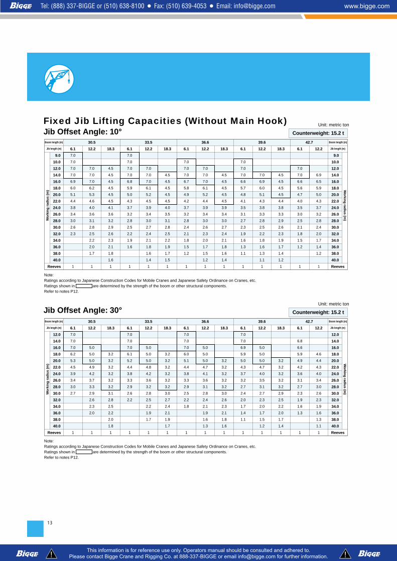
Jib Offset Angle: 30°30.5 33.5 36.6 39.6 42.7Boom length (m)
Jib length (m)
Wo
rkin
g r
adiu
s (m
) Wo
rking
radiu
s (m)
Boom length (m)
Jib length (m)6.1
7.0
7.0
7.0
6.2
5.3
4.5
3.9
3.4
3.0
2.7
1
12.2
5.0
5.0
5.0
4.9
4.2
3.7
3.3
2.9
2.6
2.3
2.0
1
18.3
3.2
3.2
3.2
3.2
3.2
3.2
3.1
2.8
2.5
2.2
2.0
1.8
1
6.1
7.0
7.0
7.0
6.1
5.2
4.4
3.8
3.3
2.9
2.6
2.2
1
12.2
5.0
5.0
5.0
4.8
4.2
3.6
3.2
2.8
2.5
2.2
1.9
1.7
1
18.3
3.2
3.2
3.2
3.2
3.2
3.2
3.0
2.7
2.4
2.1
1.9
1.7
1
6.1
7.0
7.0
7.0
6.0
5.1
4.4
3.8
3.3
2.9
2.5
2.2
1.8
1
12.2
5.0
5.0
5.0
4.7
4.1
3.6
3.1
2.8
2.4
2.1
1.9
1.6
1.3
1
18.3
3.2
3.2
3.2
3.2
3.2
3.0
2.6
2.3
2.1
1.8
1.6
1
6.1
7.0
7.0
6.9
5.9
5.0
4.3
3.7
3.2
2.7
2.4
2.0
1.7
1.4
1.1
1
12.2
5.0
5.0
5.0
4.7
4.0
3.5
3.1
2.7
2.3
2.0
1.7
1.5
1.2
1
18.3
3.2
3.2
3.2
3.2
3.2
2.9
2.5
2.2
2.0
1.7
1.4
1
6.1
6.8
6.6
5.9
4.9
4.2
3.6
3.1
2.7
2.3
1.9
1.6
1.3
1
12.2
4.6
4.4
4.3
4.0
3.4
3.0
2.6
2.3
1.9
1.6
1.3
1.1
1
12.0
14.0
16.0
18.0
20.0
22.0
24.0
26.0
28.0
30.0
32.0
34.0
36.0
38.0
40.0
Reeves
12.0
14.0
16.0
18.0
20.0
22.0
24.0
26.0
28.0
30.0
32.0
34.0
36.0
38.0
40.0
Reeves
Note: Ratings according to Japanese Construction Codes for Mobile Cranes and Japanese Safety Ordinance on Cranes, etc.Ratings shown in are determined by the strength of the boom or other structural components.Refer to notes P12.
Unit: metric ton
Counterweight: 15.2 t
9.0
10.0
12.0
14.0
16.0
18.0
20.0
22.0
24.0
26.0
28.0
30.0
32.0
34.0
36.0
38.0
40.0
Reeves
30.5 33.5 36.6 39.6 42.7
9.0
10.0
12.0
14.0
16.0
18.0
20.0
22.0
24.0
26.0
28.0
30.0
32.0
34.0
36.0
38.0
40.0
Reeves
Boom length (m)
Jib length (m)
Wo
rkin
g r
adiu
s (m
) Wo
rking
radiu
s (m)
Boom length (m)
Jib length (m)6.1
7.0
7.0
7.0
7.0
6.9
6.0
5.1
4.4
3.8
3.4
3.0
2.6
2.3
1
12.2
7.0
7.0
7.0
6.2
5.3
4.6
4.0
3.6
3.1
2.8
2.5
2.2
2.0
1.7
1
18.3
4.5
4.5
4.5
4.5
4.5
4.5
4.1
3.6
3.2
2.9
2.6
2.3
2.1
1.8
1.6
1
6.1
7.0
7.0
7.0
7.0
6.8
5.9
5.0
4.3
3.7
3.2
2.8
2.5
2.2
1.9
1.6
1
12.2
7.0
7.0
7.0
6.1
5.2
4.5
3.9
3.4
3.0
2.7
2.4
2.1
1.8
1.6
1.4
1
18.3
4.5
4.5
4.5
4.5
4.5
4.0
3.5
3.1
2.8
2.5
2.2
1.9
1.7
1.5
1
6.1
7.0
7.0
7.0
6.7
5.8
4.9
4.2
3.7
3.2
2.8
2.4
2.1
1.8
1.5
1.2
1
12.2
7.0
7.0
7.0
6.1
5.2
4.4
3.9
3.4
3.0
2.6
2.3
2.0
1.7
1.5
1.2
1
18.3
4.5
4.5
4.5
4.5
4.5
3.9
3.4
3.0
2.7
2.4
2.1
1.8
1.6
1.4
1
6.1
7.0
7.0
7.0
6.6
5.7
4.8
4.1
3.5
3.1
2.7
2.3
1.9
1.6
1.3
1.1
1
12.2
7.0
6.9
6.0
5.1
4.3
3.8
3.3
2.8
2.5
2.2
1.8
1.6
1.3
1.1
1
18.3
4.5
4.5
4.5
4.5
4.4
3.8
3.3
2.9
2.6
2.3
1.9
1.7
1.4
1.2
1
6.1
7.0
7.0
6.6
5.6
4.7
4.0
3.5
3.0
2.5
2.1
1.8
1.5
1.2
1
12.2
6.9
6.5
5.9
5.0
4.3
3.7
3.2
2.8
2.4
2.0
1.7
1.4
1.2
1
Fixed Jib Lifting Capacities (Without Main Hook)Jib Offset Angle: 10°
Note: Ratings according to Japanese Construction Codes for Mobile Cranes and Japanese Safety Ordinance on Cranes, etc.Ratings shown in are determined by the strength of the boom or other structural components.Refer to notes P12.
Unit: metric ton
Counterweight: 15.2 t

14

15
Tower Length: 36.3 mTower Jib Working Ranges
Hei
gh
t ab
ove
gro
un
d (
m)
Radius from center of rotation (m)
1.75
m
Center of rotation
1.15 m
1.1m
15゚
55゚60゚
65゚
75゚
15゚
15゚
15゚
25゚
45゚
60゚
70゚
75゚80゚
90゚
16.8 m JIB
19.8 m JIB
22.9 m JIB
25.9 m JIB
29.0 m JIB
70
65
60
55
50
45
40
35
35
30
25
20
15
10
5
454030252015105
NOTES:1. Ratings according to Japanese Construction Codes for Mobile Cranes
and Japanese Safety Ordinance on Cranes, etc.2. Ratings in metric tons for 360° working area.3. Operating radius is the horizontal distance from center of rotation to a
vertical line through the center of gravity of the load.4. Weight of hook block(s), slings and other load handling accessories is
included in rated load. Their total weight must be subtracted from ratedload to obtain weight that can be lifted.
5. Ratings shown are based on freely suspended loads and make noallowance for such factors as wind effect on lifted load, ground conditionsout-of-level, operating speeds or any other condition that could be detri-
mental to the safe operation of this equipment. Operator, therefore,has the responsibility to judge the existing conditions and reduce liftedloads and operating speeds accordingly.
6. Ratings are for operation on a firm and level surface.7. At radii and boom lengths where no ratings are shown on chart, opera-
tion is not intended nor approved.8. Tower/tower jib inserts and guy lines must be arranged as shown in the
“Operator's Manual”.9. Tower jib hoist reeving is 8 part line.
10. Gantry must be in raised position for all conditions.11. Crawlers must be fully extended for all crane operations.

12. Tower and tower jib backstops are required for all tower and tower jibcombinations.
13. Ratings shown in are determined by the strength of the toweror other structural component.
14. With a 16.8 m tower jib, a 7-ton ball hook cannot be used. 15. When erecting and lowering the tower length of 39.3 m or over, the pillow
plate for erection must be placed at the end of crawlers.16. For the erection and dismantling of a 42.4 m tower, an additional weight
for erection use (3.3 ton) must be used. Additional weight for self-erec-tion should be removed during crane operation.
17. When using a 19-ton hook with a 16.8 m tower jib, or a 7-ton ball hookwith a 19.8 m tower jib, attach a tower jib point weight (300 kg).
18. Instruction in the “Operator's Manual” must be strictly observed whenoperating the machine.
19. Tower jib ratings: Deduct weight of hook block, slings, and all other loadhandling accessories from tower jib ratings shown.
16
75
70
65
60
55
50
45
40
35
30
25
20
15
10
0
5
Hei
gh
t ab
ove
gro
un
d (
m)
Radius from center of rotation (m)Center of rotation1.1 m
29.0 m JIB
16.8 m JIB
19.8 m JIB
22.9 m JIB
25.9 m JIB
1.15 m
75˚65˚
55˚
60˚
15˚
15˚15˚
15˚
80˚
70˚
75˚90˚
1.75
m
5 10 15 20 25 30 35 40 45 50
Tower Length: 42.4 m

17
6.5 m/12.0
12.0
12.0
12.0
12.0
10.7
9.6
8.2
6.2
18.3 m/5.5
90°
15.9 m/7.4
7.3
6.4
5.6
5.0
23.7 m/4.5
75°
24.4 m/3.8
3.5
3.2
28.7 m/3.1
60°
7.3 m/12.0
12.0
12.0
11.8
10.5
9.4
8.1
7.1
5.9
21.3 m/4.6
90°
17.5 m/6.5
6.3
5.5
4.9
4.4
4.0
26.7 m/3.8
75°
26.5 m/3.3
3.1
2.8
31.6 m/2.6
60°
2 2
6.0
7.0
8.0
9.0
10.0
12.0
14.0
16.0
18.0
20.0
22.0
24.0
26.0
28.0
30.0
32.0
Reeves
Tower angle
21.0 m Tow
er Len
gth
Wo
rkin
g R
adiu
s (m
)
6.0
7.0
8.0
9.0
10.0
12.0
14.0
16.0
18.0
20.0
22.0
24.0
26.0
28.0
30.0
32.0
Reeves
Wo
rking
Rad
ius (m
)
Jib length (m) 16.8 19.8
Tower length (m) 21.0
Tower angle
Jib length (m)
Tower length (m)
6.5 m/12.0
12.0
12.0
12.0
12.0
10.7
9.6
8.2
6.2
18.3 m/5.5
90°
16.7 m/6.7
6.2
5.4
4.8
4.3
24.6 m/4.2
75°
25.9 m/3.3
3.2
2.9
2.7
30.3 m/2.7
60°
7.3 m/12.0
12.0
12.0
11.8
10.5
9.4
8.1
7.2
5.9
21.3 m/4.6
90°
18.3 m/6.0
5.3
4.7
4.3
3.8
27.5 m/3.6
75°
28.1 m/2.8
2.6
2.4
33.2 m/2.3
60°
2 2 2
6.0
7.0
8.0
9.0
10.0
12.0
14.0
16.0
18.0
20.0
22.0
24.0
26.0
28.0
30.0
32.0
34.0
36.0
38.0
Reeves
Tower angle
24.1 m Tow
er Len
gth
Wo
rkin
g R
adiu
s (m
)
6.0
7.0
8.0
9.0
10.0
12.0
14.0
16.0
18.0
20.0
22.0
24.0
26.0
28.0
30.0
32.0
34.0
36.0
38.0
Reeves
Wo
rking
Rad
ius (m
)
Jib length (m) 16.8 19.8 22.9
Tower length (m) 24.1
Tower angle
Jib length (m)
Tower length (m)
8.1 m/11.5
11.2
11.0
10.3
9.2
8.1
7.2
6.3
5.3
4.1
24.2 m/3.9
90°
19.8 m/5.3
5.3
4.7
4.2
3.8
3.5
3.2
30.4 m/3.1
75°
30.2 m/2.5
2.3
2.1
2.0
36.2 m/2.0
60°
Tower Jib Lifting Capacities
Note: Ratings according to Japanese Construction Codes for Mobile Cranes and Japanese Safety Ordinance on Cranes, etc.Ratings shown in are determined by the strength of the tower or other structural components.Refer to notes P15 and P16.
Unit: metric ton
Counterweight: 15.2 t

18
6.5 m/12.0
12.0
12.0
12.0
12.0
10.6
9.5
8.2
6.2
18.3 m/5.5
90°
18.3 m/5.7
5.1
4.5
4.0
3.7
26.1 m/3.6
75°
28.9 m/2.3
2.2
2.0
33.3 m/1.8
60°
7.3 m/12.0
12.0
12.0
11.8
10.4
9.3
8.1
7.2
5.9
21.3 m/4.6
90°
19.8 m/5.0
5.0
4.4
4.0
3.6
3.2
29.1 m/3.1
75°
31.1 m/1.9
1.8
1.7
1.5
36.2 m/1.5
60°
2 2 2 2 1
6.0
7.0
8.0
9.0
10.0
12.0
14.0
16.0
18.0
20.0
22.0
24.0
26.0
28.0
30.0
32.0
34.0
36.0
38.0
40.0
42.0
Reeves
Tower angle
30.2 m Tow
er Len
gth
Wo
rkin
g R
adiu
s (m
)
6.0
7.0
8.0
9.0
10.0
12.0
14.0
16.0
18.0
20.0
22.0
24.0
26.0
28.0
30.0
32.0
34.0
36.0
38.0
40.0
42.0
Reeves
Wo
rking
Rad
ius (m
)
Jib length (m) 16.8 19.8 22.9 25.9 29.0
Tower length (m) 30.2
Tower angle
Jib length (m)
Tower length (m)
8.1 m/11.5
11.2
11.0
10.3
9.2
8.1
7.2
6.3
5.3
4.1
24.2 m/3.9
90°
8.9 m/8.6
8.6
8.4
8.2
7.7
7.1
6.4
5.9
5.3
4.7
4.0
27.2 m/3.3
90°
9.7 m/6.2
6.2
6.2
6.0
5.6
5.1
4.6
4.2
3.8
3.5
3.2
2.8
30.1 m/2.8
90°
21.4 m/4.5
4.4
3.9
3.5
3.2
2.9
2.7
75°
22.9 m/4.0
3.8
3.4
3.1
2.8
2.6
2.4
34.9 m/2.3
75°
19.6 m/5.4
5.2
4.6
4.1
3.7
3.4
3.1
2.8
2.6
35.3 m/2.5
80°
33.3 m/1.6
1.6
1.4
1.3
39.2 m/1.2
60°
35.4 m/1.3
1.3
1.2
1.1
60°
29.0 m/2.6
2.5
2.3
2.0
1.9
1.7
1.6
40.4 m/1.5
70°
6.5 m/12.0
12.0
12.0
12.0
12.0
10.7
9.5
8.2
6.2
18.3 m/5.5
90°
17.5 m/6.2
6.0
5.3
4.7
4.2
25.3 m/3.9
75°
27.4 m/2.8
2.7
2.5
31.8 m/2.3
60°
7.3 m/12.0
12.0
12.0
11.8
10.4
9.3
8.1
7.2
5.9
21.3 m/4.6
90°
19.0 m/5.5
5.2
4.6
4.1
3.7
3.4
28.3 m/3.3
75°
29.6 m/2.4
2.3
2.1
1.9
34.7 m/1.9
60°
2 2 2 2
6.0
7.0
8.0
9.0
10.0
12.0
14.0
16.0
18.0
20.0
22.0
24.0
26.0
28.0
30.0
32.0
34.0
36.0
38.0
40.0
42.0
Reeves
Tower angle
27.1 m Tow
er Len
gth
Wo
rkin
g R
adiu
s (m
)
6.0
7.0
8.0
9.0
10.0
12.0
14.0
16.0
18.0
20.0
22.0
24.0
26.0
28.0
30.0
32.0
34.0
36.0
38.0
40.0
42.0
Reeves
Wo
rking
Rad
ius (m
)
Jib length (m) 16.8 19.8 22.9 25.9
Tower length (m) 27.1
Tower angle
Jib length (m)
Tower length (m)
8.1 m/11.5
11.2
11.0
10.3
9.2
8.1
7.2
6.3
5.3
4.1
24.2 m/3.9
90°
8.9 m/8.6
8.6
8.4
8.2
7.7
7.1
6.5
5.9
5.3
4.7
4.0
27.2 m/3.3
90°
20.6 m/4.9
4.5
4.0
3.7
3.3
3.0
31.2 m/2.9
75°
22.1 m/4.4
4.0
3.6
3.2
3.0
2.7
2.5
34.2 m/2.5
75°
31.7 m/2.1
2.0
1.9
1.7
37.6 m/1.6
60°
33.9 m/1.7
1.7
1.6
1.4
1.3
40.6 m/1.3
60°
Note: Ratings according to Japanese Construction Codes for Mobile Cranes and Japanese Safety Ordinance on Cranes, etc.Ratings shown in are determined by the strength of the tower or other structural components.Refer to notes P15 and P16.
Unit: metric ton
Counterweight: 15.2 t

19
6.5 m/12.0
12.0
12.0
12.0
12.0
10.6
9.5
8.2
6.2
18.3 m/5.5
90°
19.1 m/5.2
4.9
4.3
3.9
3.5
26.9 m/3.3
75°
30.5 m/1.8
1.6
1.5
34.8 m/1.4
60°
7.3 m/12.0
12.0
12.0
11.8
10.4
9.3
8.1
7.2
5.9
21.3 m/4.6
90°
20.6 m/4.6
4.2
3.8
3.4
3.1
29.8 m/2.8
75°
32.6 m/1.4
1.3
1.2
37.7 m/1.1
60°
2 2 2 2 1
6.0
7.0
8.0
9.0
10.0
12.0
14.0
16.0
18.0
20.0
22.0
24.0
26.0
28.0
30.0
32.0
34.0
36.0
38.0
40.0
42.0
Reeves
Tower angle
33.2 m Tow
er Len
gth
Wo
rkin
g R
adiu
s (m
)
6.0
7.0
8.0
9.0
10.0
12.0
14.0
16.0
18.0
20.0
22.0
24.0
26.0
28.0
30.0
32.0
34.0
36.0
38.0
40.0
42.0
Reeves
Wo
rking
Rad
ius (m
)
Jib length (m) 16.8 19.8 22.9 25.9 29.0
Tower length (m) 33.2
Tower angle
Jib length (m)
Tower length (m)
8.1 m/11.5
11.2
11.0
10.3
9.2
8.1
7.2
6.3
5.3
4.1
24.2 m/3.9
90°
8.9 m/8.6
8.6
8.3
8.0
7.7
7.1
6.4
5.8
5.3
4.7
4.0
27.2 m/3.3
90°
9.7 m/6.2
6.2
6.2
6.0
5.6
5.1
4.6
4.2
3.8
3.5
3.1
2.8
30.1 m/2.8
90°
17.6 m/6.2
6.0
5.2
4.7
4.2
3.8
3.4
3.1
80°
18.9 m/5.5
5.1
4.6
4.1
3.7
3.3
3.1
2.8
32.9 m/2.7
80°
20.1 m/5.0
4.5
4.0
3.6
3.3
3.0
2.7
2.5
35.9 m/2.3
80°
26.6 m/2.9
2.7
2.4
2.2
2.0
35.5 m/1.9
70°
28.3 m/2.5
2.3
2.1
1.9
1.7
1.6
38.5 m/1.5
70°
30.1 m/2.2
2.0
1.8
1.6
1.5
1.4
41.4 m/1.3
70°
6.5 m/12.0
12.0
12.0
12.0
12.0
10.6
9.5
8.2
6.2
18.3 m/5.5
90°
19.9 m/4.7
4.7
4.1
3.7
3.4
27.7 m/3.1
75°
1.3
1.2
35.3 m/1.1
60°
7.3 m/11.4
11.4
11.4
11.4
10.4
9.3
8.1
7.2
5.9
21.3 m/4.6
90°
16.8 m/6.4
5.9
5.2
4.6
4.1
3.7
27.6 m/3.4
80°
25.9 m/2.8
2.8
2.5
2.3
2.1
33.6 m/1.9
70°
2 2 2 2 1
6.0
7.0
8.0
9.0
10.0
12.0
14.0
16.0
18.0
20.0
22.0
24.0
26.0
28.0
30.0
32.0
34.0
36.0
38.0
40.0
42.0
Reeves
Tower angle
36.3 m Tow
er Len
gth
Wo
rkin
g R
adiu
s (m
)
6.0
7.0
8.0
9.0
10.0
12.0
14.0
16.0
18.0
20.0
22.0
24.0
26.0
28.0
30.0
32.0
34.0
36.0
38.0
40.0
42.0
Reeves
Wo
rking
Rad
ius (m
)
Jib length (m) 16.8 19.8 22.9 25.9 29.0
Tower length (m) 36.3
Tower angle
Jib length (m)
Tower length (m)
8.1 m/10.1
10.1
10.1
10.1
9.2
8.1
7.2
6.3
5.3
4.1
24.2 m/3.9
90°
8.9 m/8.6
8.5
8.3
8.0
7.7
7.1
6.4
5.8
5.3
4.7
3.9
27.2 m/3.3
90°
9.7 m/6.2
6.2
6.2
6.0
5.6
5.1
4.6
4.2
3.8
3.5
3.1
2.8
30.1 m/2.8
90°
18.1 m/5.8
5.1
4.5
4.1
3.7
3.3
3.0
30.5 m/3.0
80°
19.4 m/5.2
5.0
4.4
4.0
3.6
3.2
3.0
2.7
33.5 m/2.5
80°
20.7 m/4.4
4.4
3.9
3.5
3.2
2.9
2.7
2.4
2.3
36.4 m/2.2
80°
27.6 m/2.5
2.4
2.2
2.0
1.8
1.6
36.6 m/1.6
70°
29.4 m/2.1
2.1
1.9
1.7
1.5
1.4
39.5 m/1.3
70°
31.1 m/1.9
1.8
1.6
1.4
1.3
1.2
1.1
70°
Note: Ratings according to Japanese Construction Codes for Mobile Cranes and Japanese Safety Ordinance on Cranes, etc.Ratings shown in are determined by the strength of the tower or other structural components.Refer to notes P15 and P16.
Unit: metric ton
Counterweight: 15.2 t

20
6.5 m/11.4
11.4
11.4
11.4
11.0
10.4
9.5
8.2
6.2
18.3 m/5.5
90°
6.7
5.8
5.1
4.5
4.1
25.1 m/3.8
80°
25.1 m/2.8
2.6
2.4
2.1
31.7 m/1.9
70°
7.3 m/9.5
9.5
9.5
9.5
9.5
9.2
8.1
7.2
5.9
21.3 m/4.6
90°
17.3 m/6.0
5.7
5.0
4.4
4.0
3.6
3.3
28.1 m/3.2
80°
26.9 m/2.4
2.2
2.0
1.8
1.6
34.7 m/1.6
70°
2 2 2 1 1
6.0
7.0
8.0
9.0
10.0
12.0
14.0
16.0
18.0
20.0
22.0
24.0
26.0
28.0
30.0
32.0
34.0
36.0
38.0
40.0
Reeves
Tower angle
39.3 m Tow
er Len
gth
Wo
rkin
g R
adiu
s (m
)
6.0
7.0
8.0
9.0
10.0
12.0
14.0
16.0
18.0
20.0
22.0
24.0
26.0
28.0
30.0
32.0
34.0
36.0
38.0
40.0
Reeves
Wo
rking
Rad
ius (m
)
Jib length (m) 16.8 19.8 22.9 25.9 29.0
Tower length (m) 39.3
Tower angle
Jib length (m)
Tower length (m)
8.1 m/8.1
8.1
8.1
8.1
8.1
8.1
7.2
6.3
5.3
4.1
24..2 m/3.9
90°
8.9 m/6.7
6.7
6.7
6.7
6.7
6.7
6.4
5.8
5.3
4.7
3.9
27.2 m/3.3
90°
9.7 m/6.2
6.2
6.2
6.0
5.6
5.0
4.6
4.2
3.8
3.4
3.1
2.8
30.1 m/2.8
90°
18.6 m/5.4
4.9
4.4
3.9
3.5
3.2
2.9
31.0 m/2.8
80°
19.9 m/4.9
4.8
4.3
3.8
3.5
3.1
2.9
2.6
2.4
80°
21.2 m/4.4
4.2
3.8
3.4
3.1
2.8
2.6
2.3
2.2
36.9 m/2.1
80°
28.6 m/2.1
1.9
1.7
1.6
1.4
37.6 m/1.3
70°
30.4 m/1.7
1.6
1.4
1.3
1.1
39.0 m/1.1
70°
32.1 m/1.5
1.3
1.2
1.1
70°
6.5 m/9.9
9.9
9.9
9.9
9.9
9.0
8.2
7.3
6.2
18.3 m/5.5
90°
16.6 m/6.2
5.7
5.0
4.4
3.9
25.7 m/3.6
80°
26.2 m/2.3
2.1
1.9
1.7
32.8 m/1.6
70°
7.3 m/8.2
8.2
8.2
8.2
8.2
7.9
7.5
6.8
5.8
21.3 m/4.6
90°
17.9 m/5.6
5.5
4.9
4.3
3.9
3.5
3.2
28.6 m/3.1
80°
27.9 m/1.9
1.9
1.7
1.6
1.4
35.7 m/1.3
70°
2 2 2 1 1
6.0
7.0
8.0
9.0
10.0
12.0
14.0
16.0
18.0
20.0
22.0
24.0
26.0
28.0
30.0
32.0
34.0
36.0
38.0
40.0
42.0
Reeves
Tower angle
42.4 m Tow
er Len
gth
Wo
rkin
g R
adiu
s (m
)
6.0
7.0
8.0
9.0
10.0
12.0
14.0
16.0
18.0
20.0
22.0
24.0
26.0
28.0
30.0
32.0
34.0
36.0
38.0
40.0
42.0
Reeves
Wo
rking
Rad
ius (m
)
Jib length (m) 16.8 19.8 22.9 25.9 29.0
Tower length (m) 42.4
Tower angle
Jib length (m)
Tower length (m)
8.1 m/7.7
7.7
7.7
7.7
7.7
7.4
7.2
6.3
5.2
4.1
24.2 m/3.9
90°
8.9 m/6.5
6.5
6.5
6.5
6.4
6.3
6.2
5.8
5.3
4.7
3.9
27.2 m/3.3
90°
9.7 m/6.0
6.0
6.0
6.0
5.6
5.0
4.6
4.1
3.8
3.4
3.1
2.8
30.1 m/2.8
90°
19.2 m/5.1
4.8
4.2
3.8
3.4
3.1
2.8
31.6 m/2.6
80°
20.4 m/4.6
4.1
3.7
3.3
3.0
2.8
2.5
2.3
34.5 m/2.3
80°
21.7 m/4.1
4.1
3.6
3.3
3.0
2.7
2.5
2.3
2.1
37.5 m/2.0
80°
29.7 m/1.7
1.6
1.5
1.3
1.2
1.1
70°
31.4 m/1.4
1.3
1.2
35.5 m/1.1
70°
27.6 m/2.4
2.3
2.1
1.9
1.7
1.5
1.4
1.2
41.1 m/1.2
75°
Note: Ratings according to Japanese Construction Codes for Mobile Cranes and Japanese Safety Ordinance on Cranes, etc.Ratings shown in are determined by the strength of the tower or other structural components.Refer to notes P15 and P16.
Unit: metric ton
Counterweight: 15.2 t

21
Tower CapWeight: 600 kg
9.1 m Special Insert Boom for TowerWeight: 1,190 kg (with boom guy cables)
Boom TopWeight: 1,070 kg (with boom guy cables)
Counterweight AWeight: 7,510 kg
Counterweight BWeight: 7,730 kg
Base MachineWith boom base, crawlers, gantry, lower spreader,upper spreader, and wire rope for main & boom hoistwinchesWeight: 40,200 kg Width: 3,200 mm
CrawlerWeight: 6,500 kg
PARTS AND ATTACHMENTS
Boom BaseWeight: 980 kg
Insert Boom
L (mm) Weight (kg)*
3.0m 3,145 320
6.1m 6,190 520
9.1m 9,240 730*with boom guy cables

22
Dimensions: mm Weight: kg
Insert Tower Jib
Tower Jib BaseWeight: 400 kg
Attachments Weight Dimensions (L x W x H)
Auxiliary sheaveUpper spreader for boom hoistUpper spreader for tower jibLower spreader for tower jib55-ton hook32-ton hook
7-ton ball hook
Jib strut (for crane) 190 kg140 kg280 kg225 kg335 kg650 kg500 kg
160 kg
3,700 mm x 670 mm x 500 mm6.1 m insert jib (for crane) 140 kg 6,160 mm x 675 mm x 625 mm9.1 m insert boom with lug 750 kg (with guy cables) 9,240 mm x 1,350 mm x 1,500 mm6.1 m insert boom with lug 540 kg (with guy cables) 6,190 mm x 1,350 mm x 1,500 mm
1,325 mm x 540 mm x 1,285 mm1,460 mm x 300 mm x 630 mm640 mm x 610 mm x 775 mm
1,350 mm x 450 mm x 930 mm590 mm x 435 mm x 1,470 mm590 mm x 330 mm x 1,530 mm
19-ton hook 400 kg 590 mm x 385 mm x 1,270 mmø 300 mm x 815 mm
Note: Estimated weights may vary ± 2%.
Other Attachments
L (mm) Weight (kg)3.0 m 3,120 1156.1 m 6,170 195
Tower Jib TopWeight: 245 kg
Tower Jib strutWeight: 760 kg
Jib Base (For Crane)Weight: 125 kg
Jib Top (For Crane)Weight: 145 kg

KOBELCO is the corporate mark used by Kobe Steel on a variety of productsand in the names of a number of Kobe Steel Group companies.
17-1, Higashigotanda 2-chome, Shinagawa-ku, Tokyo 141-8626 JAPANTel: +81-3-5789-2130 Fax: +81-3-5789-3372
Bulletin No. 7055-3FSPEC-AO1 060901IF Printed in Japan
HYDRAULIC CRAWLER CRANE
Standard Equipment
Upper structure/Lower structure
Cab Control
Safety Device
Counterweight: 15.2 ton (total weight)760 mm shoe crawlersBatteries (2-12V,136 Ah/5 HR)Gantry raising/lowering cylinderElectric hand throttle gripVariable boom hoist speed controllerVariable main/aux. hoist speed controllerSwing neutral-free/brake select switchSide deck for cabSteps (crawlers)Two front working lightsTwo rear view mirrorsTools (for routine maintenance)Cable roller (for boom)Upper spreader storage guide
Air conditionerLuggage boxCup holderAshtrayCigar lighterIntermittent wiper & window washer (skylight and front window)Sun visorRoof blindFloor mat (cloth)Foot restShoe tray
Load Moment Indicator (with boom lowering slow stop function)LMI release key (for hook over-hoist prevention device and boom over-hoist prevention device) LCD multi displayUltimate stop function for boom over-hoistFunction lock leverPropel lever lockMechanical drum lock pawl (main, aux. and boom hoist)Signal hornSwing parking brakeMechanical swing lock pin (two positions)Swing flashers/warning buzzer
Inquiries To:
Note: Due to our policy of continual product improvements all designs and specifications are subject to change without advance notice.Copyright by KOBELCO CRANES CO., LTD. No part of this catalog may be reproduced in any manner without notice.