Embed Size (px)
Citation preview
Installation and Operation• Instructions
for
CATERPILLARilliG. u.s. PAT.0,..".
NO. 44HYDRAULIC'CONTROL
Serial Numbers6W5001..up7Wl ..up
8W5001..up9Wl ..up
PEORIACATERPILLAR TRACTOR CO.
ILLINOIS u. s.A.
FORM 1276l-3

Avoid Accidents
Mostaccidents,whether they occurin the air, inindustry, on the farm,at home,on the highways, orat sea, are caused by someone's failure to followsimple and fundamental safety rules or precautions. For this reason most accidents can be prevented by recognizing the real cause and doingsomethingabout it before the accident occurs.
Regardless of the care used in the design andconstruction of any type of equipment, there aremany conditions that cannot be completely safeguarded against without interferingwith reasonable accessibility and efficient operation.
A careful operator is the best insurance againstan accident.
The complete observance of one simple rulewould prevent many thousands of serious injurieseach year. thai rule is: --Never attempt 10 clean.oil or adjust a machine while it is in motion.··
T2646

Foreword
"Caterpillar" products are a combination of advanced engineering, skilled manufacturing, andthe finest materials metallurgical science canselect. Thousands of satisfying, economical working hours are built into each machine.
Whether or not the owner derives the maximumof service from his machine depends largely onthe care exercised in its operation and maintenance. This book is written to give the operatoressential information regarding the day-to-dayoperation, lubrication and adjustment of themachine. Careful adherence to these instructionswill result in assured economy.
A great many "Caterpillar" owners dependupon their dealer for service other than the careand adjustments described in this book. This practice is recommended because "Caterpillar" dealers have stocksofgenuine "Caterpillar" parts andare equipped with tools designed and built by"Caterpillar". Their servicemen are factorytrained and are kept closely informed by the factory regarding advanced methods of servicing"Caterpillar" products - thus, in all ways theyare equipped to render the best of service.
T 2647,/II
/j
/
/

3
Table of Contents
Page
INTRODUCTION . 4
INSTALLATION INSTRUCTIONS - GENERAL 5-6
INSTALLATION ON D6 TRACTOR - PART ONE ..Mounting Group and Hydraulic Control Installation -No. 44 Hydraulic Control Applications on D6 Tractor -Attachments
7-20
INSTALLATION ON D4 TRACTOR - PART TWOMounting Group and Hydraulic Control Installation -No. 44 Hydraulic Control Applications on D4 Tractors -Attachments
20-35
INSTALLATION ON D2 AND R2 TRACTORS - PART THREE.. 35-45Mounting Group and Hydraulic Control Installation -No. 44 Hydraulic Control Applications on D2 and R2Tractors - Attachments
LUBRICATION INSTRUCTIONS 45-51General Lubricating Information - Crankcase Lubricating Oil -_ Ball and Roller Bearing Lubricant - Lubrication Chart
OPERATION INSTRUCTIONSPreparation for Use - Operation - Daily Care
51-54
MAINTENANCE INSTRUCTIONSCare of the hydraulic System
54-55
INDEX 56
CAPACITIES Inside Back Cover
LOCATION OF SERIAL NUMBER. Inside Back Cover

4
IntroductionThe hydraulic system is designed to give long life when operated
with clean oil. Special attention is given during manufacturing andshipping at the factory to insure an absolutely clean system.
The metal parts of the hydraulic system are treated with a specialacid solution to remove any dirt, scale or abrasive material, then a corrosion resistant coating is applied to guard against undesirable oxidation. Suitable covers are used for shipping to cover the openings of thehydraulic control, cylinders, hoses and lines to exclude dirt and moisture.Keep the covers so they can be used again to protect the openings in thehydraulic system if the equipment is disassembled or removed for anyreason.
To obtain maximum service. cleanliness must be the rule. Be carefulto avoid introducing dirt into the hydraulic system when installing, fillingwith oil and replacing lines or hoses during any maintenance operation.
Retighten the clamp bolts on all hose connections about two weeksafter the hose is placed in service so there will be compensation for theinitial set of the rubber and a tight joint will result.
"KEEP IT CLEAN"
Installation InstructionsGENERAL
The No. 44 Hydraulic Control can be installed on the D6. D4 and D2tractors as a basic installation which is covered in the first topic in eachpart of the book. Several arrangements can be installed either individually or more than one at a time. by adding the various arrangementsof hydraulic lines to the basic installation and are covered in the ATTACHMENTSsections of the book.
The application of the various arrangements of lines for the D6 installation are:
(l) One Implement
(2) Scraper or Two Implement
(3) Tool Bar
The applications of the various arrangements of lines for the D4 installation are:
(l) Bulldozer
(2) Tool Bar
(3) No. 40 Scraper or Two Implements
(4) One Implement
(5) Bulldozer and One Implement
(6) Bulldozer and Tool Bar
(7) Bulldozer and No. 40 Scraper or Two Implements
The applications of the various arrangements of lines for the D2 installations are:
(l) Bulldozer
(2) One Implement
(3) Bulldozer and One Implement
(4) Two Implements
(5) Bulldozer and Two Implements
The hydraulic surge tank (l) is used with No. 40 Scraper applicationsand two hydraulic implements. These applications will also have twosets of pipes extending to the rear of the tractor and two levers shownat the upper right corner of the control. In applications where the hydraulic surge tank is not used a filler neck will be installed at (3). and
5
6 INSTALLATION INSTRUCTIONS
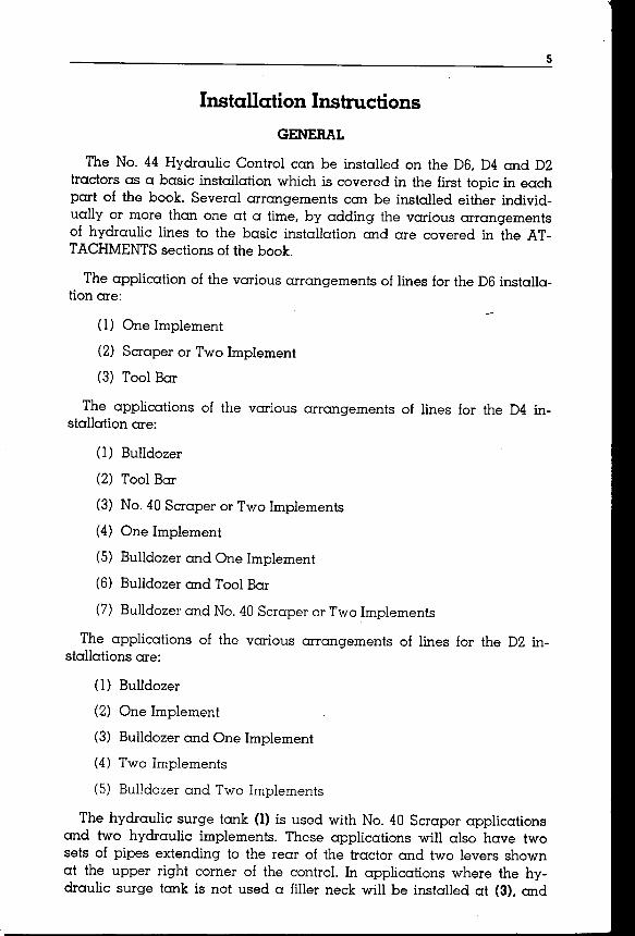
HYDRAULIC CONTROL FOR BULLDOZERAND EITHER SCRAPER OR TWO IMPLEMENT OPERATION ON D4 TRACTOR
I-Hydraulic surge tank. 2-Long pipe assembly. 3-Location of filler neck or connection of hydraulic surge tank andcontrol. 4-Single lever for single valveoperation. (Two levers on double valve
controls.) 5-Basic pipe assembly.6-Pump guard .
•
plates will cover the openings in the hydraulic control instead of the longpipe assembly (2). On single valve operations a single lever (4) and thebasic pipe assembly (5) will be used on the control. In bulldozer arrangements the pump guard (6) is supplied and if so desired can be obtainedas an attachment for other arrangements.
The hydraulic control may be partially mounted on the tractor at thefactory or it may be shipped not installed and processed for shipping. Ifit is received disassembled and processed for shipping the dirt sealingand rust proofing applications should be carefully removed. The coversshould be saved for future use, if the unit is removed or another application of the control is desired.
CAUTION
"Caterpillar" hydraulic cylinders for agricultural implementcontrol are the double acting type. Only double acting cylinders should be used with the No. 44Hydraulic Control.Cylinders of five inch bore and up to twelve inch stroke, or those ofapproximately the same volume should be used with the hydraulic control equipped with pump of 25 G.P.M. capacity.Damage to the implement may result if cylinders smaller thanfive inch bore and twelve inch stroke are used with a controlequipped with a 37G.P.M.pump. The use of single acting cylinders is not recommended when the No.44Hydraulic Controlis equipped with either pump since damage to the hydrauliccontrol may result.
Supplied with the hydraulic control are hardware, ring seals, bolts,nuts and lockwashers placed in bags and tagged for identification.
7
Part OneInstallation On D6 Tractor
MOUNTING GROUP ANDHYDRAULIC CONTROL INSTALLATION
The hydraulic control mounts on the front of the tractor and is drivenfromthe front of the crankshaft pulley.
A new radiator lower guard which will replace the standard radiatorlower guard is also supplied with the control.
See the topic, ATTACHMENTSwhen installing the various arrangements of hydraulic lines.
Drive Coupling Installation on D6 Tractors
Remove the radiator lower guard and the crankshaft pulley guardbetween the engine front support and the radiator lower guard if thetractor is so equipped.
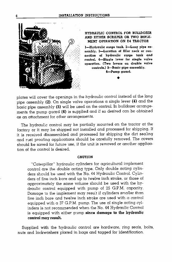
Install the universal joint (2) to the crankshaft pulley with eight capscrews (1) and lockwashers.
Install the new radiator lower guard (4) in the tractor frame channelsand fasten it with six large bolts (3), nuts and lockwashers furnished withthe group. It may be necessary to remove excess welding material frominside the frame channels to make the radiator lower guard fit properly.Install four mounting studs (5) in the guard. Inspect the flange coupling
INSTALLING UNIVERSAL JOINTI-Capscrew. 2-Universal joint.
INSTALLATION OF HYDRAULICCONTROL
3-Bolts. 4-Radiator lower guard.S-Mounting studs. 6-Couplingbracket. 7-Flange coupling.

8 INSTALLATION INSTRUCTIONS-D6 TRACTOR
(7) to be sure the plug is in the flange end. Fasten the flange coupling(7) to the universal joint with eight bolts, nuts and lockwashers and position the flange coupling in the hole in the radiator lower guard. Cleanthe flange coupling as well as the bearings (8) and (9), spacer (12), seal(10) and coupling bracket (6) in kerosene or some non-inflammablecleaning fluid, then work a lubricant into the bearings before assembly.Install front bearing (9), spacer (12), rear bearing (8), retainer ring (11)and dust seal (10) in the coupling bracket as shown. Be sure the lip ofseal (10) is turned outward, away from the lubricant chamber. Removethe ten capscrews (14) from the rear of the hydraulic control which holdthe pump retainer cover (13) in place. Earlier controls which have arough facing on the pump retainer cover (13) will require a new coverwith a machined face. Install coupling bracket (6) to the hydraulic control and fasten with ten longer capscrews and lockwashers.
COUPLING BRACKET ASSEMBLY6-Coupling bracket. 7-Flange coupling. 8-Rear bearing. 9-Front bearing. IO-Dust
seal. ll-Retainer ring. l2-Spacer. 13-Pump retainer cover. l4-Capscrews.
REAR OF HYDRAULIC CONTROL
When installing the coupling bracket to the hydraulic control, makesure the hole for the lubricant fitting is toward the bottom.
Hydraulic Control Installation On D6 Tractors
Lift the hydraulic control into position and guide flange coupling (7)into coupling bracket (6). Align the drive coupling and pump shaftsplines then push the control on the four mounting studs in the radiatorlower guard. Install the nuts and lockwashers on the four mounting studs(5) and tighten them securely. Fasten brackets (16) to the hydraulic control and radiator lower guard with four capscrews (15) and lockwashers.

INSTALLATION INSTRUCTIONS-OS TRACTOR 9
INSTALLATION OF BRACKETS
I5-Capscrews. IS-Brackets .
•
Basic Hydraulic Pipes and Control LeverInstallation On D6 Tractor
Whenever the hydraulic control is installed, the basic hydraulic pipesand control lever with connecting rods must be installed with one or acombination of the groups in the topic, ATTACHMENTS.
Rework Seat Side Plate, Right Fender And Fender Sheet: Layout anddrill three 13/32 inch (10.3mm.) holes in the front face (A) of the seat sideplate using hole (B), already in the plate for a starting location, as instructed in the illustration. These holes will be used for installation of theoperating control lever bracket.
CONTROL LEVER BRACKET MOUNTINGHOLE LOCATIONS
A-Front face of seat side plate.B-Hole already in plate .
•
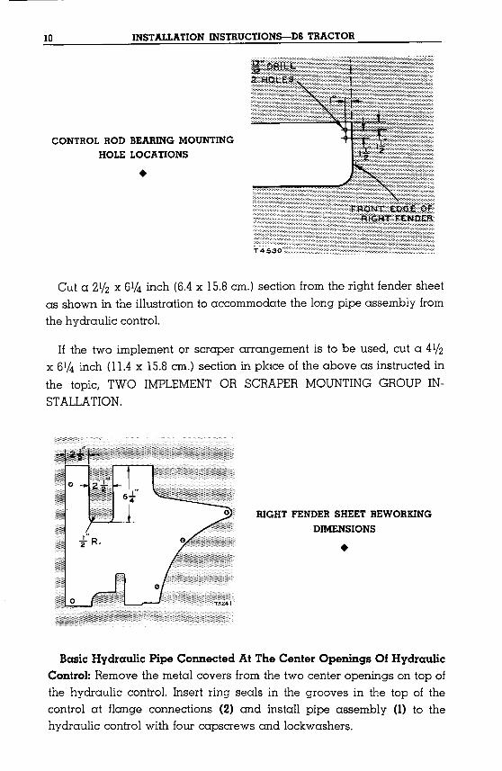
Drill two 17/32 inch (13.4 mm.) holes in the right fender as shown tomount the control rod bearing.
10 INSTALLATION INSTRUCTION5-D6 TRACTOR
CONTROL ROD BEARING MOUNTINGHOLE LOCATIONS
•
Cut a 211z x 61/4 inch (6.4 x 15.8em.) section from the right fender sheetas shown in the illustration to accommodate the long pipe assembly fromthe hydraulic control.
If the two implement or scraper arrangement is to be used, cut a 4lfzx 61/4 inch (11.4x 15.8em.) section in place of the above as instructed inthe topic, TWO IMPLEMENTOR SCRAPER MOUNTING GROUP INSTALLATION.
RIGHT FENDER SHEET REWORKINGDIMENSIONS
•
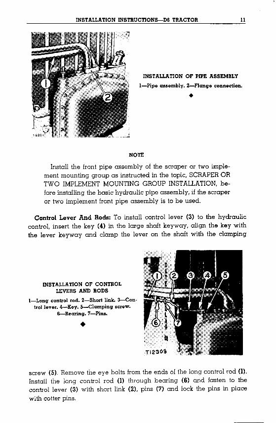
Basic Hydraulic Pipe Connected At The Center Openings Of HydraulicControl: Remove the metal covers from the two center openings on top ofthe hydraulic control. Insert ring seals in the grooves in the top of thecontrol at flange connections (2) and install pipe assembly (1) to thehydraulic control with four capscrews and lockwashers.
INSTALLATION INSTRUCTIONS-DS TRACTOR 11
INSTALLATION OF PIPE ASSEMBLY
I-Pipe assembly. 2-Flange connection.
•
NOTE
Install the front pipe assembly of the scraper or two implement mounting group as instructed in the topic, SCRAPERORTWO IMPLEMENTMOUNTINGGROUP INSTALLATION,before installing the basic hydraulic pipe assembly, if the scraperor two implement front pipe assembly is to be used.
Control Lever And Rods: To install control lever (3) to the hydrauliccontrol, insert the key (4) in the large shaft keyway, align the key withthe lever keyway and clamp the lever on the shaft with the clamping
INSTALLATION OF CONTROLLEVERS AND RODS
I-Long control rod. 2-Short link. 3-Con·trol lever. 4-Key. 5-Clamping screw.
S-Bearing. 7-Pins .
•
screw (5). Remove the eye bolts from the ends of the long control rod (1).Install the long control rod (1) through bearing (6) and fasten to thecontrol lever (3) with short link (2), pins (7) and lock the pins in placewith cotter pins.

12 INSTALLATION INSTRUCTIONS-OS TRACTOR
Control Rod Bearing And Operating Control Lever Bracket: Install thecontrol rod bearing (3) on rod (4) and fasten the bearing to the rightfender with two bolts, nuts and lockwashers (1), but do not tighten. Installlubricant fitting. Fasten operating control lever bracket (5) to seat platewith four bolts, nuts and lockwashers. Connect short rod (7) between longcontrol rod (8) and lever (6) with pins and cotter pin. Lubricate all bearing points so that the rods move freely.
Move the operating control lever until any binding in the control rodsand bearings is removed. Tighten bolts and nuts on right fender bearing.The control lever should operate freely with no binding in the bearingpoints.
INSTALLING CONTROL ROD BEARING ANDOPERATING CONTROL LEVER BRACKET
I-Bolts. 2-Fitting. 3-Bearing. 4-Control rod. 5-Bracket. S-Lever.7-Short rod. 8-Long rod.
NO. 44 HYDRAULIC CONTROL APPLICATIONS ON D6 TRACTOR
The No. 44 Hydraulic Control can be used in several arrangementseither individually or more than one at a time. This is accomplished byadding the various hydraulic lines and control lever to the basic hydraulic control pipe and control lever just installed.
Following is a list of some of the possible arrangements which can beinstalled on the tractor to operate the hydraulically controlled equipment:
1. One Implement, single valve, 25 G.P.M.pump.
2. Two Implements or Scraper, double valve, 37 G.P.M.pump with hydraulic surge tank.
3. Two Implements, double valve, 25 G.P.M.pump with hydraulic surgetonl..
4. ToolBar, single valve, 37G.P.M.pump.

INSTALLATION INSTRUCTIONS-OS TRACTOR 13
The installation instructions of the various individual arrangements arecovered in the following topics. The installation, operation and maintenance instructions for the equipment being controlled will be found inthe Operator's Instructions furnished with each equipment group orarrangement.
The hydraulic control is designed to operate with double actingcylinders of limited dimensions. The use of single acting cylinders is notrecommended since damage to the control may result.
ATTACHMENTS
One Implement Group Installation On D6Tractor
This group can be installed on the tractor after the installation of thebasic hydraulic pipe and control lever as instructed in the topic, BASICHYDRAULICPIPE AND CONTROLLEVERINSTALLATION.
RIGHT SIDE OF" PLATE
1-6f~T5206
REAR PLATE REWORKING INSTRUCTIONS(As viewed from rear of tractor)
Rework Right Fender Brace And Rear Plate: Remove rear plate fromtractor. Layout and cut holes as instructed in the illustration. Removethe floor plates just ahead of the seat. Shut off the fuel at valve (2) and
•SEAT AND FUEL TANK REMOVALI-Support. 2-Vaive. 3-Fuelline .

14 INSTALLATION INSTRUCTIONS-D6 TRACTOR
disconnect the fuel line (3). Remove the three capscrews along each sidewhich hold the seat to the support (1). Cut a 411z inch (11.5em.) sectionfrom the right fender brace (4), as shown. Remove upper two nuts fromtransmission case rear center cover and install bracket (5) supplied inmounting group bag.
RIGHT FENDER BRACEREWORKING INFORMATION
4-Fender brace. 5-Bracket .
•
Pipe Assembly: Remove cover from front of pipe flange and clean offany sealing materials, dirt or paint from around the flange openings.Insert a ring seal in pipe flange (6) and position pipe assembly (7) inplace on the right rear side of the transmission case. Fasten the pipeassembly (7) with two bolts nuts and lockwashers to the pipe connectedto the two center openings of the hydraulic control. Fasten rear of pipeassembly to bracket (8) with a bolt, nut and lockwasher. Fasten fuel tankand seat to tractor, connect fuel line and open fuel line valve and replacefloorplates. Install rear plate on tractor.
INSTALLATION OF ONE IMPLEMENTPIPE ASSEMBLY
6-Flanqe. 7-Pipe assembly. 8-Bracket .
•

INSTALLATION INSTRUCTIONS-OS TRACTOR 15
Two Implement Or Scraper MountingGroup Installation On D6 Tractor
The front pipe assembly of this group must be installed before the basichydraulic pipe can be installed. See the topic, BASICHYDRAULICPIPEAND CONTROL LEVER INSTALLATION.A second control lever andconnecting rods are also included in this group.
Cut a 4ljz x 61/4 (14.4x 15.8cm.) section from the right fender sheet asshown in the illustration to accommodate the two implement pipe assembly from the hydraulic contro!'
RIGHT FENDER SHEETREWORKING DIMENSIONS
•
Cut a section from the rear plate as shown for the scraper line assemblies.
LE F T 51DE OF PLATE
,.3Is R.
T5216
REAR PLATE REWORKING INFORMATION(As Viewed From Rear of Tractor)
Pipe Assembly: Remove the metal covers from the two outer openingson top of hydraulic control and clean off any sealing material, dirt orpaint from around the openings in the pipe connections. Insert a ring sealin the grooves in the top of the control at flange connections (2).
IS INSTALLATION INSTRUCTIONS-OS TRACTOR
NOTE
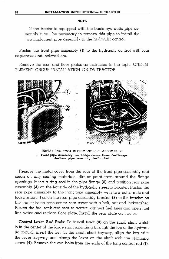
If the tractor is equipped with the basic hydraulic pipe assembly it will be necessary to remove this pipe to install thetwo implement pipe assembly to the hydraulic control.
Fasten the front pipe assembly (1) to the hydraulic control with fourcapscrews and lockwashers.
Remove the seat and floor plates as instructed in the topic, ONE IMPLEMENTGROUP INSTALLATIONON D6 TRACTOR.
INSTALLING TWO IMPLEMENT PIPE ASSEMBLIESI-Front pipe assembly. 2-Flange connections. 3-Flange.
4-Rear pipe assembly. 5-Bracket.
Remove the metal cover from the rear of the front pipe assembly andclean off any sealing materials, dirt or paint from around the flangeopenings. Insert a ring seal in the pipe flange (3) and position rear pipeassembly (4) on the left side of the hydraulic steering booster. Fasten therear pipe assembly to the front pipe assembly with two bolts, nuts andlockwashers. Fasten the rear pipe assembly bracket (5) to the bracket onthe transmission case center rear cover with a bolt, nut and lockwasher.Fasten the fuel tank and seat to tractor, connect fuel lines and open fuelline valve and replace floor plate. Install the rear plate on tractor.
Control Lever And Rods: To install lever (3) on the small shaft whichis in the center of the large shaft extending through the top of the hydraulic control, insert the key in the small shaft keyway, align the key withthe lever keyway and clamp the lever on the shaft with the clampingscrew (4). Remove the eye bolts from the ends of the long control rod (1).
INSTALLATION INSTRUCTIONS-DB TRACTOR 17
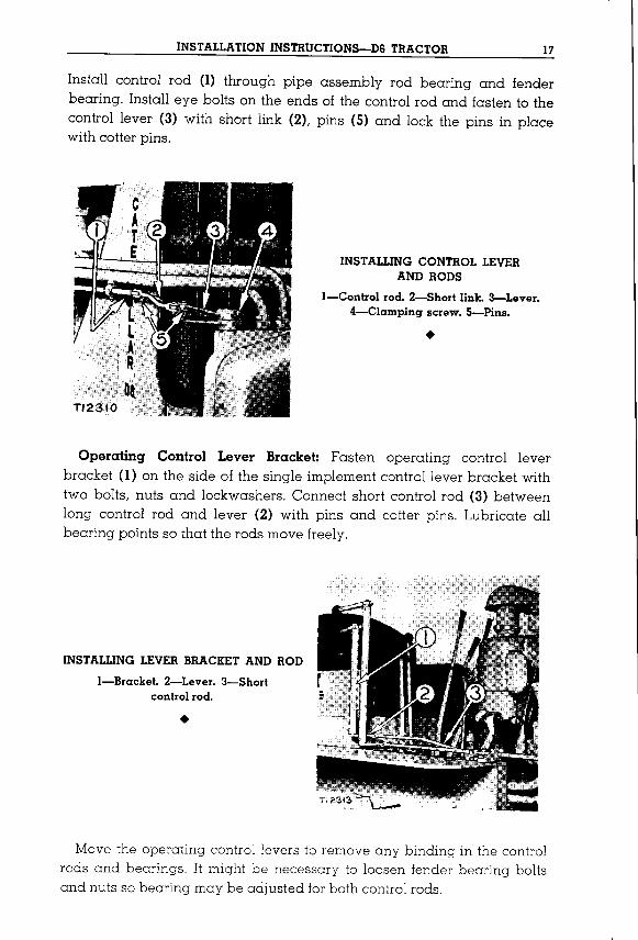
Install control rod (1) through pipe assembly rod bearing and fenderbearing. Install eye bolts on the ends of the control rod and fasten to thecontrol lever (3) with short link (2), pins (5) and lock the pins in placewith cotter pins.
INSTALLING CONTROL LEVERAND RODS
I-Control rod. 2-Short link. 3-Lever.4-Clamping screw. 5-Pins .
•
Operating Control Lever Bracket: Fasten operating control leverbracket (1) on the side of the single implement control lever bracket withtwo bolts, nuts and lockwashers. Connect short control rod (3) betweenlong control rod and lever (2) with pins and cotter pins. Lubricate allbearing points so that the rods move freely.
INSTALLING LEVER BRACKET AND ROD
I-Bracket. 2-Lever. 3-Shortcontrol rod.
•
Move the operating control levers to remove any binding in the controlrods and bearings. It might be necessary to loosen fender bearing boltsand nuts so bearing may be adjusted forboth control rods.
18 INSTALLATION INSTRUCTIONS-OS TRACTOR
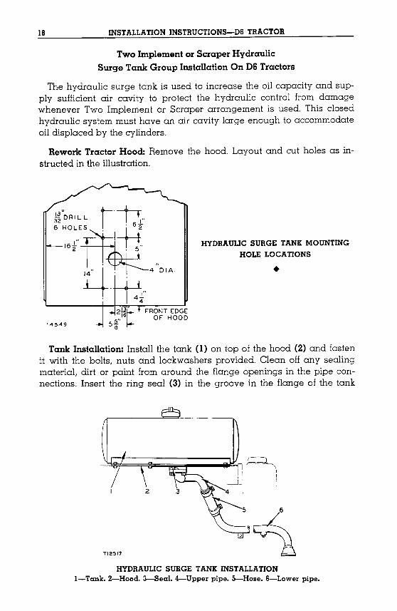
Two Implement or Scraper HydraulicSurge Tank Group Installation On D6 Tractors
The hydraulic surge tank is used to increase the oil capacity and supply sufficient air cavity to protect the hydraulic control from damagewhenever Two Implement or Scraper arrangement is used. This closedhydraulic system must have an air cavity large enough to accommodateoil displaced by the cylinders.
Rework Tractor Hood: Remove the hood. Layout and cut holes as instructed in the illustration.
~fDRILL t·n..6 HOLES , Ln
16.tTmL'T:.,2 I, ,5 ..4 4 D"
HYDRAULIC SURGE TANK MOUNTINGHOLE LOCATIONS
•FRONT EDGE
OF HOODT4549
Tank Installation: Install the tank (1) on top of the hood (2) and fastenit with the bolts, nuts and lockwashers provided. Clean off any sealingmaterial, dirt or paint from around the flange openings in the pipe connections. Insert the ring seal (3) in the groove in the flange of the tank
HYDRAULIC SURGE TANK INSTALLATIONI-Tank. 2-Hood. 3-Sea1. 4-Upper pipe. 5-Hose. S-Lower pipe.
INSTALLATION INSTRUCTIONS-D6 TRACTOR 19
and fasten the upper pipe (4) to the flange with the capscrews and lockwashers provided. Install and clamp hose (5) to the upper pipe.
Install the hood with tank on the tractor being careful to prevent dirtfromentering the hydraulic oil passages.
Remove the cover from the top left opening of the hydraulic controland clean off any sealing materiaL dirt or paint from around the openings of the hydraulic control and pipe. Install the lower pipe (6) in thehose (5) and fasten the pipe to the hydraulic control with capscrews andlockwashers provided with the hydraulic control. Be sure the gasketbetween the hydraulic control and lower pipe will properly seal thehydraulic oil system. Clamp the hose to the lower pipe. Using the holein the lower pipe bracket as a template, drill a 13/32 inch (10.3mm.) holein the radiator side guard and then fasten the pipe bracket to the guardwith bolt, nut and lockwasher.
Tool Bar Line Group Installation On D6Tractor
Remove the seat and floor plates then rework the right fender brace asinstructed in the topic, ONE IMPLEMENTGROUPINSTALLATIONOND6TRACTOR.The rear plate between the seat and transmission case is notused with the tool bar line group.
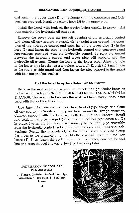
Pipe Assembly: Remove the cover from front of pipe flange and cleanoff any sealing materials, dirt or paint from around the flange openings.Connect support with the two rear bolts to the fender bracket. Installring seals in the pipe flange (1) and position tool bar pipe assembly (3)in place. Fasten the tool bar pipe assembly to the front pipe assemblyfrom the hydraulic control and support with two bolts (2), nuts and lockwashers. Fasten the brackets (4) to the transmission case and clampthe pipes to the brackets with the U-bolts provided. Install the tool barhoses (5). Then fasten the seat fuel tank to the tractor, connect the fuelline and open the fuel line valve. Replace the floorplates.
INSTALLATION OF TOOL BARPIPE ASSEMBLY
I-Flange. 2-Bolts. 3-Tool bar pipeassembly. 4-Brackets. 5-Tool bar
hoses•
•
20
Part TwoInstallation On D4 Tractor
MOUNTINGGROUP ANDHYDRAULICCONTROLINSTALLATION
The hydraulic control can be installed on all D4 Tractors. Three different drive couplings are needed and these coupling installation proceduresare included in the following three topics.
The hydraulic control mounts on the front of the tractor and is drivenfrom the front of the crankshaft. Drain and remove the radiator and oilcooler from all tractors.
See the topic, ATTACHMENTSwhen installing the various arrangements of hydraulic lines.
Drive Coupling Installation On D4 Tractors
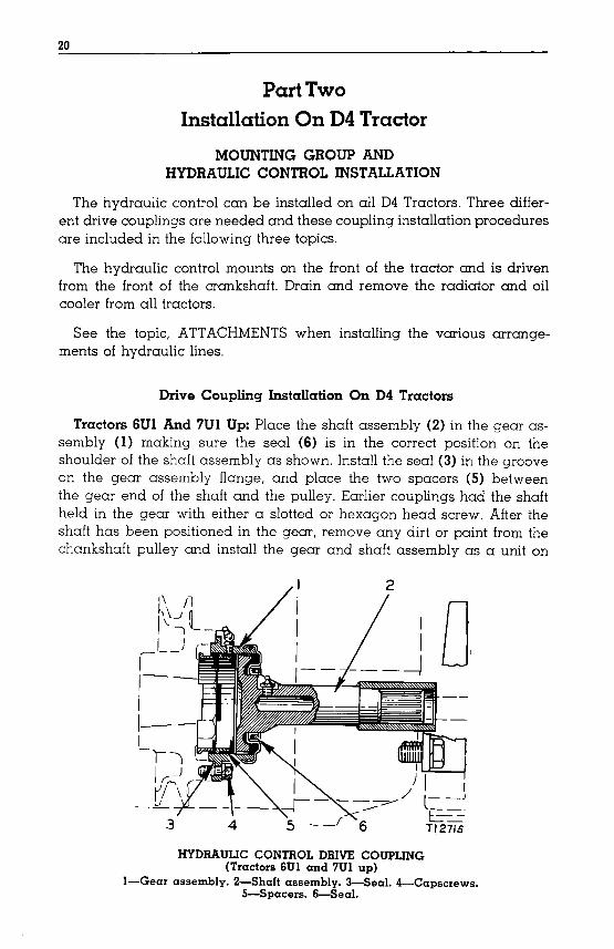
Tractors 6UI And 7UI Up: Place the shaft assembly (2) in the gear assembly (1) making sure the seal (6) is in the correct position on theshoulder of the shaft assembly as shown. Install the seal (3) in the grooveon the gear assembly flange, and place the two spacers (5) betweenthe gear end of the shaft and the pulley. Earlier couplings had the shaftheld in the gear with either a slotted or hexagon head screw. After theshaft has been positioned in the gear, remove any dirt or paint from thechankshaft pulley and install the gear and shaft assembly as a unit on
f'1 /lI\~~l_I )~--
II-II-I-I)
I r: _J _Jr_""",",rl"\
_L..
3 4
HYDRAULIC CONTROL DRIVE COUPLING(TractorsSUI and 7Ul up)
I-Gear assembly. 2-Shaft assembly. 3-Seal. 4-Capscrews.5-Spacers. S-Seal.
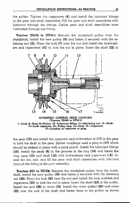
U.M.Ol.{SSDAenndetHO~urel.{~Ue~SDJpUDHDl.{Sel.{~JOpueel.{~leAO(IZ)leAO;)pUD(SZ)~e)]:sD6leAOJel.{~nD~suI·(IZ)leAO;)U1(SZ)IDesel.{~nD~SUI·Aenndel.{~U1(ZZ)HDl.{Sel.{~pesuI·e;)DldU~muel.{~)]:;)01oi(CZ)s.M.el;)sdD::>pUDslel.{sD.M.)]:::>01=nnDfSu1PUDmuel.{~leAO(81))]:::>01=ne::>Dld·(tZ)mu6u1u1D~elel.{~l.{E.M.Alem::>esEue~sDJpUD(61)Aennd.M.euel.{~nD~SU~'HDl.{S-)]:UDl::>el.{~urOlJAenndHDl.{S)]:UDl::>el.{leAoureH:tOISIl01IDtSlOI:lDll
·A]quressDlOe6el.{~U~6umlJel.{~l.{6noll.{~
~UD;)1lqnll.{P.M.senquressDHDl.{SPUDlOe6eq~unPUD'ljeqUDJel.{~nD~S-UI·(SOs.M.el::>sdwPUDslel.{sD.M.)]:::>O] l.{P.M.(ZOHDl.{SPUD(SOlOe6'6U1lel.{~uaisojPUD(to6U~lel.{~U~seAOOl6eq~U1(8)S]DeSel.{~nD~suI·(01)s6uHln~uD::>1lqn]el.{~nD~suI·l.{::>und)]:::>1ldDl.{H.M.e::>D]dU1pe)]:D~seqp]nol.{sl.{::>~l.{.M. rzn~D6n]dDpesnsfitrqdnoo=n=a·lOe6el.{~U1HDl.{Sel.{~P]ol.{oilOe6el.{~U1(lI)~Dlel.{sD.M.)]:::>O] PUD.M.el::>sdD::>=nnD~su1PUDrsnlOe6el.{~
·.6nldlOM9l:>sdD:>JOUOHD:>O"l-t.1·M9l:>sdD:J-91·.JD9!)-SI·.6upA9l1nd-t1·M9.J:>sdD:>:11:>0"1-;:1
·IJD1{S-Z:I·Inu.6U!U!DI911-11·.6umsIUD:>pqn"l-OI·A9I1nd-&·ID9S-8·:II:>O"l-L.(IUL.lS01tOISIL.SlO\:>Dll)
!)NI"ldnO:J3AIlIO"lOlllNO:J:JI"lnVIIOA.H
U1(ZI)HDl.{Sel.{~pesuI·e::>D]dU1~nuel.{~)]:::>0]o~(CI)s.M.el::>sdD::>pUDSle-qSD.M.)]:::>O] el.{~nDfSu1pUD~nuel.{~leAO(l))]:::>0]el.{~e::>D]d.(II)~nu6U1U~D~-eleq~l.{H.M.A]em::>esEue~SDJPUD(6)Aennd.M.euel.{~nD~SU~'HDl.{S)]:UDl::>el.{~urOlJAenndHDl.{S)]:UDl::>al.{~eAoureH:IItllS01tOISILsloPDll
·6uTHlJeuol.{6noll.{~pe~D::>pqn]ele.M.seHquressDHDl.{SPUDlOe6leHlO3:·s6umlJel.{~l.{6noll.{~~UD::>pqn]l.{H.M.senquressDHDl.{SPUDlOe6el.{~lEd·se1]quressDlJDl.{sPUDlOe6el.{~U~s6umlJ~uD::>1lqn]el.{~llDiSU~PUD(t)s.M.el::>sdD::>el.{~ueil.{6u·Aenndel.{~
IZ1I0l:JVlIltoSNOIl:JnlllSNINOIlV"I"lVlSNI

22 INSTALLATION INSTRUCTIONS-D4 TRACTOR
HYDRAULIC CONTROL DRIVE COUPLING(Tractors 4Gl to 715104)
IS-Lock. IS-Pulley. 20-Capscrew. 21-Cover. 22-Shaft. 23-Lock capscrews.24-Retaining nut. 25-Gasket. 26-Seal. 27-Angle washer. 2S-Spacer.
2S-Spacer at outer edge of radiator.
with the lockwashers and capscrews (20). Install the two fittings in thepulley and fill the pulley and shaft assembly with lubricant through afitting.
Reinstall The Radiator On D4 Tractors
Install the radiator and oil cooler group on the tractor, and install thefour studs and the two dowels in the radiator bottom tank. The dowelsare not necessary on tractors before 5T7411.Fill the cooling system witha suitable coolant.
CUT GUARD 8.SCREEN HERE
(Tractors 6Ul & 7Ul up) (Tractors 71731Sto 5T7411)RADIATOR GUARD SCREEN REWORKING INSTRUCTIONS
On tractors 6UI and 7UI up remove the two lower capscrews that holdthe radiator screen guard to the radiator bottom tank. Slot the screenlower mounting holes as shown. On tractors before 5T7411the radiatorscreen guard can be reworked to permit easy removal of the screen forcleaning.
°:l[UDlaqltoa6pa.ramoaqllO:l[UOluIOHOq10lO~pOlaqlpUO(SZ)sreoodsaqluaaNq-aqpeoojdamotdo;aAoqoaqlU~psuonueur(t.Z)slaqsO.M.aI6ulf°:l[UDlaqltoa6pa1alnoaqlro:l[UOlurouoq10lO~p01=npUOSla:l[;)OlqI01lUW;)!jnOlpAqaqluaa.M.laqpUO~I01lUO;);)!jnDlpAqaqlpUO:l[UOlurouoq10l-O~p01aqlUaa.M.laqHoqsaAFPaqlpunompasnamsreoodsasaq.LCa60dsnotxard0uovOIS.:ILoiIDvSlOPOlllOt6u!jdnwaA~lpIOllUO;);)HnDlp-AqtouOHDllsnmaqlaas)'(SZ)puc(SZ)sreoodstouomppoaqlqp.M.sotdo;snotxardO.M.laqlutpaq~l;)Sapsoamosaqlst6I8L1La10taqSlOP01luoI01lUW;)HnDlpAqaqltouOHollolSU~=u:SICL.ft.aloJagSlOI:JD1l
°:l[uOl=ntoa6pa1alnoaqllo:l[UDlmonoq10lO~pOlaqlpuosla:l[;)Olqaqluaa.M.laqpsocqdaqPInoqs'laqloaqluo:l[;)1qlq;)U~virpuoa6paauouo:l[;)~qlq;)U~9118amq;)1q.M.'(a60dsno~Aa1d0uovOIs1L0lIDvSlOPOlllOt6uHdnwaA~lpIOllUW;)lIno1pAqtoUO~lDllsnmaas)'(t.z;)slaqsO.M.aI6uoloqllda;)xa;)~dOlsno~Aaldaqlu1paq~l;)Sapsoamosaqls~IIVL.LS0l6I8LILSlOP01lUOI01lUO;);)!jno1p-Aq,cqltouOHollolSU~aq.L=lUt.1S01SICt.lt.Slol:JD1lt{HM.aAH:JaJJ3
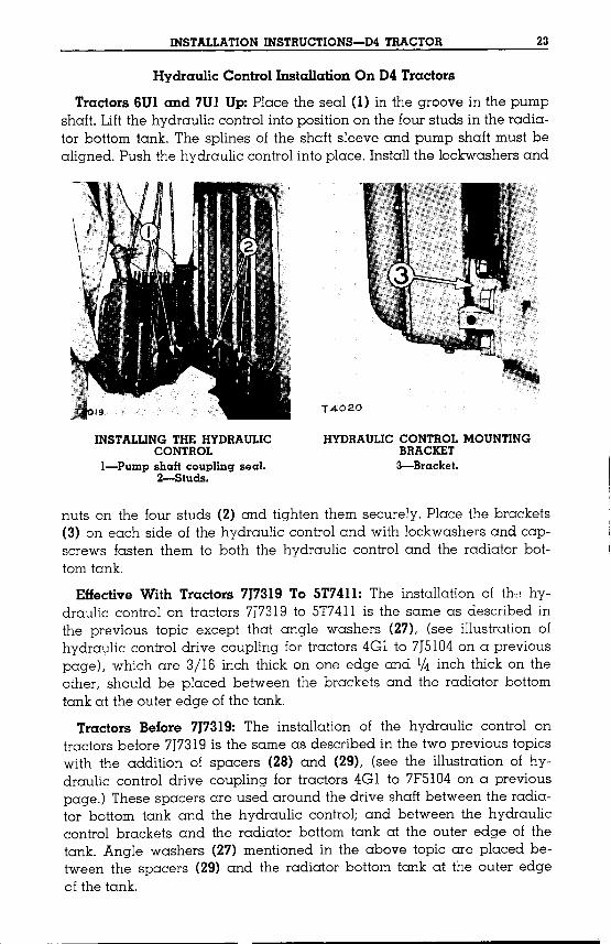
°:l[UOlmOl-loq10lO~pOlaqlpuoIOllUO;);)!jno1pAqaqlqloq0lmaqlualsqS.M.a1;)S-do;)puoslaqso.M.:l[;)0Iqp.M.puoIOllUO;);)!jnDlpAqaqltoap~sq;)oauo(C)sla:l[;)Olqaqla;)oId°AIam;)asmaqlualq6~lpuo(Z)spnlsmOtaqluoslnu
'Ialj;)IUII-C13}1:::>VHII
DNI1Nnow'IOH1NO:::>:::>I'InVHGA.H
'SpnlS-j';'IDes.6uHdno;)IJDl{Sdwnd-I
'IOH1NO:::>:::>I'InVHGA.H3HlDNI'I'IV1SNI
pUOslaqsO.M.:l[;)0IaqlllolsuI°a;)0Id0lU~IOllUO;);)!jnDlpAqaqlqsnd°pau6!joaqlsnmuoqsdmndpUOaAaaIsuoqsaqltosau!jdsaq.L°:l[UDlmonoq10l-O~pOlaqlU1spnlsmOtaqluouomsodOlU~I01lUW;)!jnDlpAqaqlun°HoqsdmndaqlU1aA0016aqlU1(I)Ioasaqla;)oId:dfilfit.pUDlfi9SlOI:JD1l
SlOI:JD1ltouOuOHDIIDlSUJ:1011UO:):JnnDlpAH
CZH01:::>VHltG-SNOIl:::>nH1SNINOI1V'I'IV1SNI

24 INSTALLATION INSTRUCTIONS-D4 TRACTOR
Crossover Valve. Basic Hydraulic PipesAnd Control Lever Installation On D4Tractors
See the HT4Shovel Operator's Instruction Book for installation instructions of line and control levers.
Whenever the complete basic hydraulic control is installed, the crossover valve, the basic hydraulic pipes and control lever with connectingrods must be installed with one or a combination of the groups in thetopic, ATTACHMENTS.
Rework Right Fender: Cut or drill two 13/32 inch 00.3 mm.) holes inthe right fender for the crossover valve (2) as shown in the followingillustration.
CROSSOVER VALVE AND CONTROL LEVER BRACKET MOUNTINGHOLE LOCATIONS
(Tractors 6U5843 and 7U11952 Up)
Drill the three 15/32 inch 01.9 mm.) holes in the right fender, as shownto mount the control lever bracket (1). On tractors before 7J7319,drill the
TRACTORS BEfORE 7J731B MOVE ALLa" TOWARD THE fRONT EDGE Of fENDER
T4021
CROSSOVER VALVE AND CONTROL LEVER BRACKETMOUNTING HOLE LOCATIONS
(Tractors Before 6U5843 and 7U11952)
control lever bracket mounting holes two inches closer to the front of thetractor than is shown in the preceding illustration. The tool box on earliertractors must be moved to a new location so the control bracket can beinstalled.

INSTALLATION INSTRUCTIONS-D4 TRACTOR 2S
Crossover Valve: When the crossover valve (2) is installed on the tractor right fender, the covers over the hydraulic passages in the valve willbe on the front, right and rear sides of the valve.
NOTE
Install the long pipe assembly of the scraper or two implement mounting group as instructed in the topic, SCRAPERORTWO IMPLEMENTMOUNTINGGROUP INSTALLATION,before installing the basic hydraulic pipe assembly if the longpipe assembly is to be used.
Basic Hydraulic Pipe Between Control And Crossover Valve: Removethe cover from the front of the crossover valve (2) and clean off anysealing materials, dirt or paint from around the openings in the pipe connections.
Remove the covers from the two center openings on top of the hydraulic control. Insert the ring seals in the grooves in the flange connections(6) and (8) of the control and crossover valve. A light coating of greaseon the seals will hold them in the grooves. Install the pipe assembly (3)between the crossover valve and hydraulic control, with the lockwashersand capscrews provided. On tractors before 7J7319,place the two inchspacer between the pipe and crossover valve. Fasten the valve to thefender with the capscrews and lockwashers provided.
Place a 1/4 inch spacer under the crossover valve on tractors notequipped with heavy duty fenders.
It may be necessary to slot the crossover valve mounting holes to prevent imposing a strain on the hydraulic pipe.
Control Levers and Rods: Bolt the operating control lever bracket (1)in place on the right fender with three bolts, nuts and lockwashers. Ontractors before 6U5843and 7Ul1952there is a reinforcement plate whichis to be bolted under the fender to give added support to the earlier controllever brackets. Put the operating control lever and washer on the outside end of the shaft in the bracket and install the cotter pin. The lubricantfitting in the lever should be to the front.
Insert the short offset end of the front control rod (7) through the outside bearing in the crossover valve (2). Install the locknuts on the eyebolts and install the bolts in both ends of the front control rod.
To install the hydraulic control long bottom lever (4) on the large control shaft which extends through the top of the hydraulic control, insertthe key in the shaft keyway, align the key and lever keyway and clampthe lever on the shaft with the clamping capscrew.
26 INSTALLATION INSTRUCTIONS-D4 TRACTOR
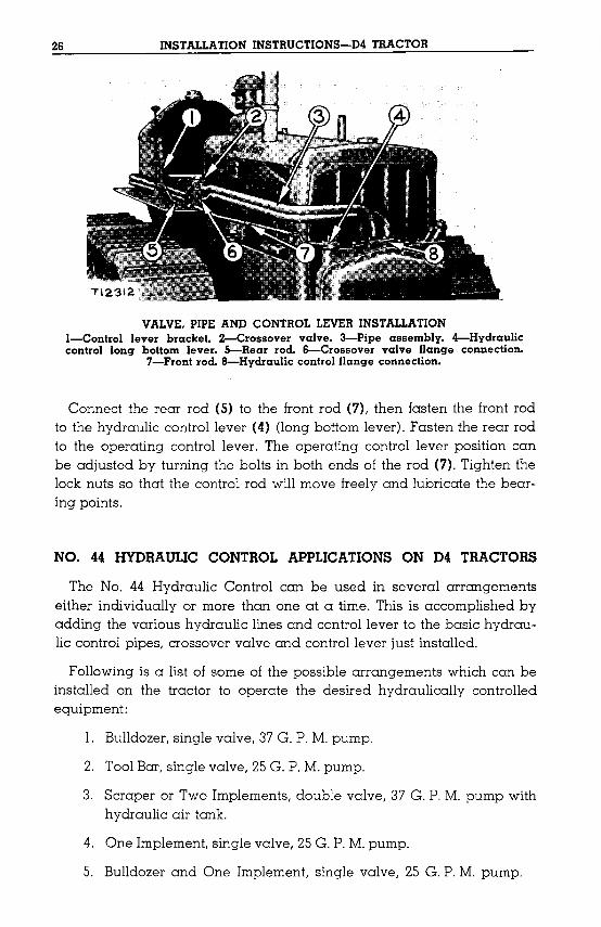
VALVE. PIPE AND CONTROL LEVER INSTALLATIONI-Control lever bracket. 2-Crossover valve. 3-Pipe assembly. 4-Hydrauliccontrol long bottom lever. 5-Rear rod. 6-Crossover valve flange connection.
7-Front rod. 8-Hydraulic control flange connection.
Connect the rear rod (5) to the front rod (7), then fasten the front rodto the hydraulic control lever (4) (long bottom lever). Fasten the rear rodto the operating control lever. The operating control lever position canbe adjusted by turning the bolts in both ends of the rod (7). Tighten thelock nuts so that the control rod will move freely and lubricate the bearing points.
NO. 44 HYDRAULIC CONTROL APPLICATIONS ON D4 TRACTORS
The No. 44 Hydraulic Control can be used in several arrangementseither individually or more than one at a time. This is accomplished byadding the various hydraulic lines and control lever to the basic hydraulic control pipes, crossover valve and control lever just installed.
Following is a list of some of the possible arrangements which can beinstalled on the tractor to operate the desired hydraulically controlledequipment:
1. Bulldozer,single valve, 37G. P.M.pump.
2. ToolBar, single valve, 25G. P.M.pump.
3. Scraper or Two Implements, double valve, 37 G. P.M. pump withhydraulic air tank.
4. One Implement, single valve, 25G. P.M.pump.
5. Bulldozer and One Implement, single valve, 25 G. P.M. pump.
'lauoap1~0aqj,noj,su~aH'dn016aqj,qgM.pand-dnsir-upuolaqsoM.:lJ:::JoI 't)oqqgM.lapuataqj,OJ,j,a:lJ:::JOlqaqj,uaj,sod'j,ald-uroi°,lOtj,a:lJ:::JOlq=nfitrrsnlapuat+talaqj,trtaloq('wwS'O!)q::JU!6S/S1auomIppuoedtdSS01:)aqj,topua+talaqj,OJ,(I)j,a:lJ:::JOlqaqj,uaj,sod
'ad!dSSOl;)aqj,P10M.0j,IoasqHM.adtdSS01:)puosa6uoUasoqaqj,uaaM.j,aqpa;)oIdaqPlnoqsHsdtdSSOl;)aqj,uopaqs!umtS!aj,0Idlaj,dopoaqj,uaq.M.
'sall.o016aqj,U!waqj,PloqlHM.sloasaqj,uoasoa16to6unoO;)j,q6nV'all.Ioll.la1l.0SS01;)aqj,puosuonoeuuooa6uoUesoq;)n-nOlpAqaqj,uaaM.j,aqH6u~dwopAqall.Ioll.aqj,OJ,(Z)sdtdSSOl;)aqj,uaj,sotpuoall.Ioll.la1l.0SS01;)aqj,U!saaoo.rfiaqj,U!SIDas6U!1aqj,j,lasuI'uonosu-uooaqj,j,osmupnj,slnotaqj,6U!1I.0WalAqad~dj,alu11!0aqj,WOltlauoap110alHuaaqj,all.owaH'suo!pauuo;)ad!dSSOl;)aqj,U!s6u!uadoaqj,punolOUlOltj,u10d10P!P'SIO!laj,Ow6unoasAUOHOuoappUOall.Ioll.la1l.0SS01;)aqj,toap!sj,q611aqj,WOltla1l.0;)aqj,all.owaH:dnlnt.pUDIn9S.l0I:>D.l1
'NOI.LV11V.LS-NIH3:A3:110H.LNO:)GNV3:dId:)l1flVHG.A.H:)ISVS:'3:A1VAH3:AO-SSOH:)';)!doj,aqj,u1papnlj,su1solall.arrOlj,UO;)puoad1d;)nnOlpAq;)!soqaqj,touOHon0j,su1aqj,lauD10POlj,aqj,uopan0j,SU!aqUO;)dno16s1q.L
SlN3WH~\f11\f
'j,uawa6uOllO10dno16j,uawd!nbaq;)oaqHM.paqs!u-mtsuo!pnlj,suIS,lOj,OladOaqj,U!puno}aqlHM.panOlj,UO;)ou!aqluaUl-d!nbaaqj,lOtSUOH;)nlj,SU!a::Juouaj,U!OUl pUOuonolado'uoHOnOISU!aq.L
'unsa.lADW10.llUO:>aqlOJaDDWDpa:>U!spapuawwo:>a.lIOUS!s.lapU!IA:>DU!I:>DalDU!sJOasnaq1'SUo!suaW!ppaHwHJOs.lapU!1A:>DU!J:>DalqnopAUDqH.M.aJD.ladoOJpaUD!SapS!10.lluo:>:>HnD.lpAqsq1
':lJ:0oquon:::mlj,suIS,lOj,-OladOIall.oqsv.LHaqj,U!pa18l1.o;)aqll!M.SIOlj,UO;)pUOsaunIall.oqsv.LHaqj,lOtSUO!pnlj,SU!UOHon0j,SU!aq.L's::J!doj,OU!M.0nOtaqj,U!palall.o;)alOsj,uawaouOllOIonp!lI.!pu!SnO!lOlI.aqj,tosUOn::mlj,sU!u01j,0n0j,sU!aq.L
'Iall.0qsaqj,qHM.paqs!umJsaunpuo:lJ:u0.L'dwnd'w'd''.:)£S'all.Ioll.alqnop'Iall.oqsv.LH'6
':lJ:UOj, a6ms::JnnOlpAqqnM.dUlnd'W'd''.:)£S'all.Ioll.alqnop'j,uawaldwIOM..L10ladol;)SlaqnapUOlazOpnns:'8
'dwnd'W'd''.:)~Z'all.Ioll.alou!s'lOS:IOo.LpuolazOpnns:'£
')jUOIaoms;)nnolpAqqnM.'dwnd'w'd''.:)~Z'all.Ioll.alqnop'j,uawaldwIOM..L'9
I.Z'H01:>'If'H.LtaSNOI1:>n'H.LSNINOI1'lf'I'I'lflSNI
28 INSTALLATION INSTRUCTIONS-D4 TRACTOR
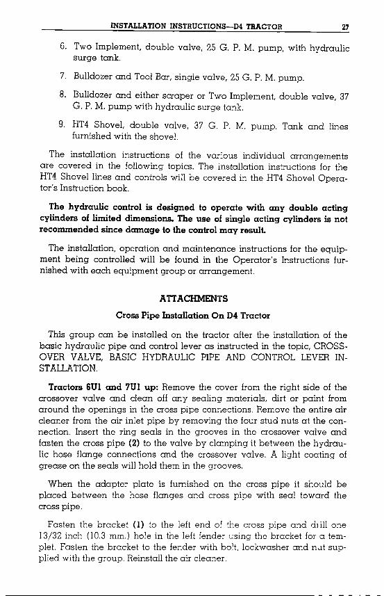
CROSS PIPE INSTALLATIONI-Bracket. 2-Cross pipe.
Tractors Before 6Ul and 7Ul: Installation is the same as for the abovetractors except that the Diesel engine air cleaner does not have to beremoved.
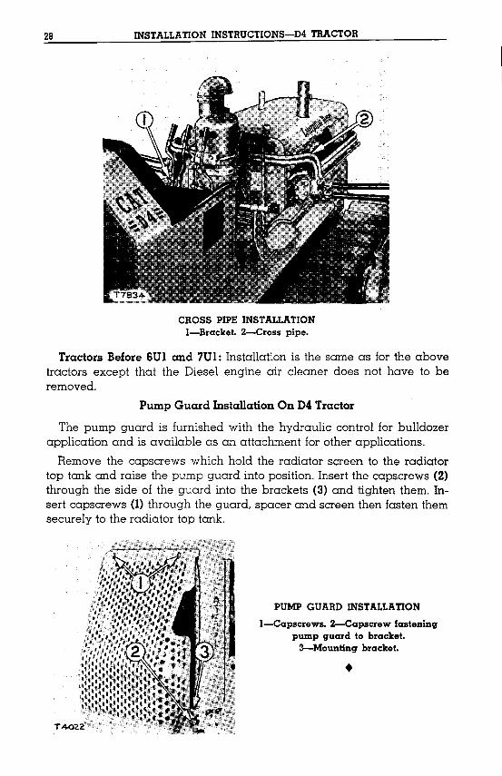
Pump Guard Installation On D4 Tractor
The pump guard is furnished with the hydraulic control for bulldozerapplication and is available as an attachment for other applications.Remove the capscrews which hold the radiator screen to the radiator
top tank and raise the pump guard into position. Insert the capscrews (2)through the side of the guard into the brackets (3) and tighten them. Insert capscrews (1) through the guard, spacer and screen then fasten themsecurely to the radiator top tank.
PUMP GUARD INSTALLATION
I-Capscrews. 2-Capscrew fasteningpump guard to bracket.3-Mounting bracket .
•

INSTALLATION INSTRUCTIONS-D4 TRACTOR 29
No. 64 Tool Bar Lines Group Installation On D4 Tractor
This group can be installed on the tractor after the installation of thehydraulic control, basic hydraulic pipe and control lever as instructed inthe topic, CROSSOVER VALVE,BASIC HYDRAULICPIPE AND CONTROLLEVERINSTALLATION.
To install the tool bar lines, remove the seat whether equipped withseat or fender mounted fuel tank. The same tool bar pipe is used foreither type fuel tank.
Remove the cover from the rear of crossover valve and clean anysealing material, dirt or paint from around the openings in the pipe connections. Insert the ring seals in the grooves in the crossover valve body,then fasten the front end of the pipe to the crossover valve (3).
Fasten the rear end of the pipe with the pipe bracket to the tool barlift frame bracket. See the No. 64 TOOL BAROPERATOR'SINSTRUCTION BOOK, for information on the installation of the tool bar lift framebracket and cylinder.
Fender Mounted Fuel Tank: Drill six 13/32 inch (10.27mm.) holes in thefenders as shown in the fender drilling diagram. These holes are formounting two brackets which raises the operator's seat. The bracketsare not required if a seat mounted fuel tank is used. Install the seat withbrackets on the fenders using the bolts, lockwashers and nuts provided.
FENDER DRILUNG DIAGRAM
•~"DRILL326 HOLES
REAR EDGEOF FENDf:R74'04
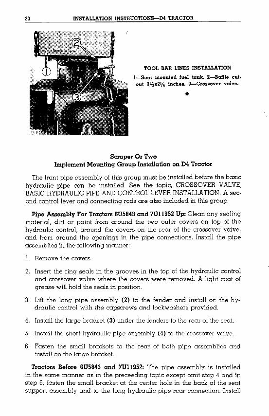
Seat Mounted Fuel Tank: Before installing the seat mounted fuel tank(I), remove a section from the right end of the baffle, 311z inches by 21/4inches as shown at (2). This should be done by cutting with a hacksaw,thus about 1/4 inch of the baffle will remain on the bottom of the tank atthis location. Install the seat mounted fuel tank on the fenders.
30 INSTALLATION INSTRUCTIONS-D4 TRACTOR
TOOL BAR LINES INSTALLATION
l-Seat mounted fuel tank. 2-Baffle cutout 31/2x21/4 inches. 3-Crossover valve .
•
Scraper Or TwoImplement Mounting Group Installation on D4 Tractor
The front pipe assembly of this group must be installed before the basichydraulic pipe can be installed. See the topic, CROSSOVERVALVE,BASICHYDRAULICPIPEANDCONTROLLEVERINSTALLATION.A second control lever and connecting rods are also included in this group.
Pipe Assembly For Tractors 6U5843 and 7U1l952 Up: Clean any sealingmateriaL dirt or paint from around the two outer covers on top of thehydraulic control, around the covers on the rear of the crossover valve,and from around the openings in the pipe connections. Install the pipeassemblies in the followingmanner:
1. Remove the covers.
2. Insert the ring seals in the grooves in the top of the hydraulic controland crossover valve where the covers were removed. A light coat ofgrease will hold the seals in position.
3. Lift the long pipe assembly (2) to the fender and install on the hydraulic control with the capscrews and lockwashers provided.
4. Install the large bracket (3) under the fenders to the rear of the seat.
5. Install the short hydraulic pipe assembly (4) to the crossover valve.
6. Fasten the small brackets to the rear of both pipe assemblies andinstall on the large bracket.
Tractors Before 6U5843 and 7U1l952: The pipe assembly is installedin the same manner as in the preceeding topic except omit step 4 and instep 6, fasten the small bracket at the center hole in the back of the seatsupport assembly and to the long hydraulic pipe rear connection. Install

INSTALLATION INSTRUCTIONS-D4 TRACTOR 31
SHORT TOP LEVER AND PIPEINSTALLATION
I-Short top lever. 2-Pipeassembly.
•
the large bracket to the short hydraulic pipe rear connection. Usingthe large bracket as a template, drill a 13/32 inch (10.3mm.) hole in theseat support assembly and fasten the bracket to the support with thelockwasher, bolt and nut provided.
Control Levers And Rods: Place the operating control lever (5) andwasher on the inside end of the shaft in the fender mounted bracket andinstall the cotter pin. The lubricant fitting in the lever should be to thefront.
To install the short top lever (I) on the small shaft which is in the center of the large shaft which extend through the top of the hydraulic control, insert the key in the small shaft keyway, align the key with the leverkeyway and clamp the lever on the shaft with the clamping capscrew.
LARGE BRACKET AND PIPEINSTALLATION
3-Large bracket. 4-Pipe assembly.
•
32 INSTALLATION INSTRUCTIONS-D4 TRACTOR
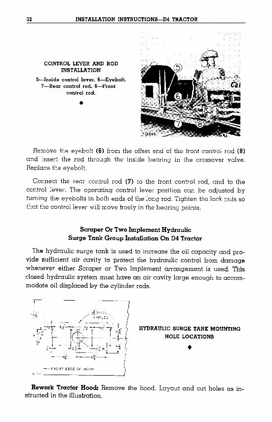
CONTROL LEVER AND RODINSTALLATION
S-Inside control lever. 6-Eyebolt.7-Rear control rod. a-Front
control rod.
•
Remove the eyebolt (6) from the offset end of the front control rod (8)and insert the rod through the inside bearing in the crossover valve.Replace the eyebolt.
Connect the rear control rod (7) to the front control rod, and to thecontrol lever. The operating control lever position can be adjusted byturning the eyebolts in both ends of the long rod. Tighten the lock nuts sothat the control lever willmove freely in the bearing points.
Scraper Or TwoImplementHydraulicSurge Tank Group Installation On D4Tractor
The hydraulic surge tank is used to increase the oil capacity and provide sufficient air cavity to protect the hydraulic control from damagewhenever either Scraper or Two Implement arrangement is used. Thisclosed hydraulic system must have an air cavity large enough to accommodate oil displaced by the cylinder rods.
.---~-----
--FRONT EDGEOF HOOD
HYDRAULIC SURGE TANK MOUNTINGHOLE LOCATIONS
•
Rework Tractor Hood: Remove the hood. Layout and cut holes as instructed in the illustration.

INSTALLATION INSTRUCTIONS-D4 TRACTOR 33
Tank Installation: Install the tank (1) on top of the hood and fasten it,with the reinforcing plate (2), on the bottom side of the hood, with thebolts, lockwashers and nuts provided. Clean off any sealing materials,dirt or paint from around the openings in the pipe connection. Insert thering seal (3) in the groove in the flange of the tank and fasten the upper
TI2307
_____5 \~
HYDRAULIC SURGE TANK INSTALLATIONI-Tank. 2-Reinforcing plate. 3-Seal. 4-Upper pipe.
S-Hose. 6-Lower pipe.
pipe (4) to the flange with the lock washers and capscrews provided.Install and clamp hose (5) to the upper pipe.
Install the hood with tank, on the tractor being careful to prevent dirtentering the hydraulic oil passage.
Remove the cover from the top left opening of the hydraulic controland clean off any sealing material, dirt or paint from around the openings in the lower pipe connection. Install the lower pipe (6) in the hoseand fasten the pipe to the hydraulic control with lock washers and capscrews provided with the hydraulic control. Be sure the gasket betweenthe lower pipe and hydraulic control will properly seal the hydraulic system oil. Clamp the hose to the lower pipe.
One Implement Group Installation On D4 Tractor
Pipe Assembly For Tractor 6U5843 And 7U11952 Up: Clean any sealingmaterial, dirt or paint from around the covers on the rear of the cross.over valves, and fromaround the openings in the pipe connections.
Install the pipe assembly in the followingmanner:
1. Remove the covers.
2. Insert the ring seals in the grooves in the crossover valve (5). A lightcoating of grease on the seals will hold them in position.

34 INSTALLATION INSTRUCTIONS-D4 TRACTOR
3. Fasten the small bracket (3) to the short hydraulic pipe rear connection (2).
4. Install the large bracket (1) under the fenders and to the rear of theseat.
5. Fasten the short hydraulic pipe assembly (4) to the crossover valvewith capscrews and lockwashers provided.
6. Fasten the pipe assembly to the large bracket.
Tractors Before 6U5843 And 7U11952: The pipe assembly is installedin the same manner as in the preceding topic except omit step 4 and instep 6, fasten the small bracket at the center hole in the back of the seatsupport assembly and to the short hydraulic pipe rear connection. Usingthe large bracket as a template, drill a 13/32 inch (10.3mm.) hole in theseat support assembly and fasten the bracket to the support with thelockwasher, bolt and nut provided.
ONE IMPLEMENT GROUP INSTALLATIONI-Large bracket. 2-Rear connection. 3-Small bracket. 4-Pipe
assembly. 5-Crossover valve.

35
Part ThreeInstallation On D2 And R2 Tractors
MOUNTINGGROUP ANDHYDRAULICCONTROLINSTALLATION
The hydraulic control mounts on the front of the tractor and is drivenfrom the front of the crankshaft. Drain and remove the radiator and oilcooler from all tractors.See the topic, ATTACHMENTSwhen installing the various arrange
ments ofhydraulic lines.
DriveCoupling Installation On D2 and R2TractorsThe hydraulic control can be installed on all D2 and R2 Tractors. Dif
ferent drive couplings are needed for D2 Tractors before 4Ul and SUIand R2 Tractors, than for D2 tractors effective with 4Ul and SUI. Thesetwo coupling installation procedures are included in the following twotopics.Effective With Tractors 4Ul and SUI: Place the shaft assembly (6) in
the gear (1) and install the seal (2) making sure it is in the correct position against the shoulder in the gear. Install the capscrew and lockwasherat (3) in the gear so the shaft assembly is held in the gear, earlier couplings used a plug at (3) which should be staked in place with a prickpunch. Clean the bore in the crankshaft pulley install the gasket, supplied with the group, in the bore. Then fill the gear with lubricant andinstall the drive coupling as a unit on the crankshaft pulley (4). Tightenthe capscrews (S) and install the lubricant fitting in the crankshaft pulley.Install the radiator on the tractor.
HYDRAULIC CONTROL DRIVECOUPLING INSTALLATION
I-Gear. 2-Seal. 3-Capscrew or retaining plug installed here. 4-Crank
shaft pulley. 5-Capscrew.6-Shaft assembly.
•
Effective With Tractors 3JL 4JL SJl and 6Jl: Layout and cut away aportion of the bottom of the radiator shell as shown.Position the radiator support plate (13)supplied in the bulldozer ship
ment in the opening cut in the radiator shell (15)as shown and weld in

36 INSTALLATION INSTRUCTIONS-D2 AND R2 TRACTORS
7" I1------'-"----16e -------I
RADIATOR BOTTOM SHELL REWORKING DIMENSIONS
place. With a 3fa inch filletweld all the way around at the joint. See illustration on page 37for reference.After reworking the radiator bottom shell remove the crank jaw from
the crankshaft and install the crankshaft pulley capscrew and lock (1).Align the holes in the pulley and lock, then install the six studs (10) inthe crankshaft pulley. The lugs on the lock should point toward the frontof the tractor.
REAR EDGE OfRADIATORSHELL
T35S3
REAR EDGE OFRADIATORSHELL
T3S54-
LOCA TING SUPPORT PLATE(Tractors 3J2555 - up: 511276 - up:
4J63 - up and 61130 - up)(Tractors 311 to 3J2555: 511 to 511276:
411 to 4J63 and 611 to 61130)
Assemble the hydraulic control drive shaft. Insert the oil seal (1I) in thecover (5) with the lip of the seal out. Install the lubricant fitting (4) in thecover (5). Slip the cover over the drive shaft (6).Install the drive shaft coupling (2) on the crankshaft pulley studs (10).
Then install the gasket (3). Position the drive shaft in the drive shaftcoupling (2) and install the nuts and lockwashers (12) fastening it securely to the pulley.Install the radiator on the radiator mounting bracket (14) and fasten it
securely with the eight capscrews provided in the shipment.
INSTALLATION INSTRUCTIONS-D2 AND R2 TRACTORS 37
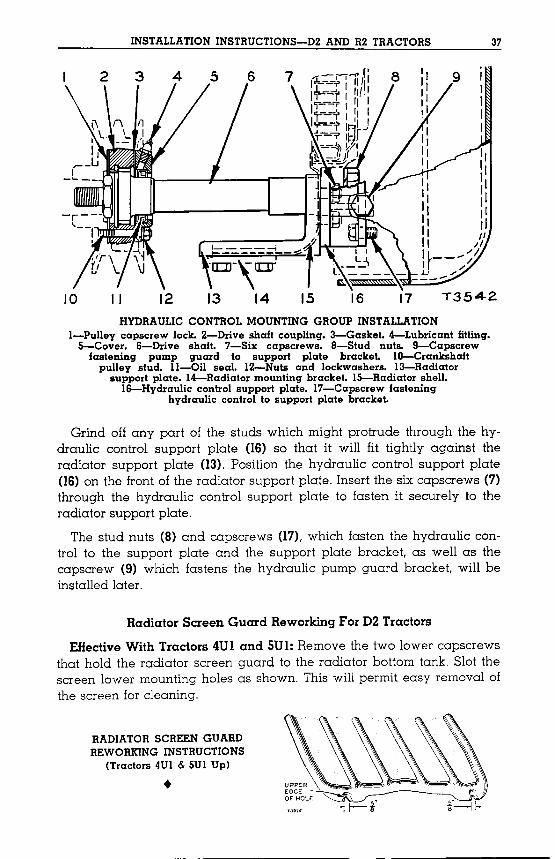
10 II 12 13 14 15 16 17 T3542
HYDRAULIC CONTROL MOUNTING GROUP INSTALLATIONI-Pulley capscrew lock. 2-Drive shaft coupling. 3-Gasket. 4-Lubricant fitting.S-Cover. 6-Drive shaft. 7-Six capscrews. a-Stud nuts. 9-Capscrewfastening pump guard to support plate bracket. IO-Crankshaftpulley stud. ll-Oil seal. 12-Nuts and lockwashers. 13-Radiatorsupport plate. 14-Radiator mounting bracket. IS-Radiator shell.
16-Hydraulic control support plate. 17-Capscrew fasteninghydraulic control to support plate bracket.
Grind off any part of the studs which might protrude through the hydraulic control support plate (16) so that it will fit tightly against theradiator support plate (13). Position the hydraulic control support plate(16) on the front of the radiator support plate. Insert the six capscrews (7)through the hydraulic control support plate to fasten it securely to theradiator support plate.
The stud nuts (8) and capscrews (17), which fasten the hydraulic control to the support plate and the support plate bracket, as well as thecapscrew (9) which fastens the hydraulic pump guard bracket, will beinstalled later.
Radiator Screen Guard Reworking For D2 Tractors
Effective With Tractors 4UI and SUI: Remove the two lower capscrewsthat hold the radiator screen guard to the radiator bottom tank. Slot thescreen lower mounting holes as shown. This will permit easy removal ofthe screen for cleaning.
RADIATOR SCREEN GUARDREWORKING INSTRUCTIONS
(Tractors 4UI & SUI Up)
•
'Mel:lsdD:::>-l'lell:lDlq.6uHunoW-g
NOI1VTIV1SNIl:nI:::>VHB:!:>NI1NnOW10H1NO:::>:::>I1nVHaA.H
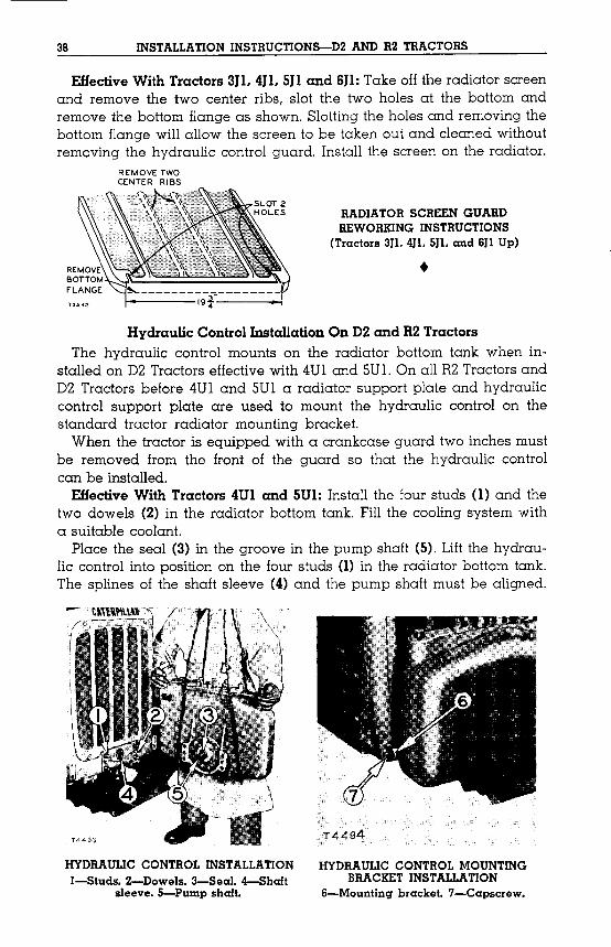
'lJDqsdwnd-S'eAee[SHDt{S-l>'[DeS-&'S[eMOa-Z'SpnlS-I
NOI1V11V1SNI10H1NO:::>:::>I1nVHaA.H
'peu6nDeqisnurHDqSdumdeqlPUD(t)eAeeIsHDqSeqlJOsauqdseq.L':l{UDlUlonoq.I0lD!PD.IeqlU!(I)spnlsmOJ=nuououtsod0lU!I0.IlUO;);)n-nD.rpKqeqlun'(S)HDqSdumdeqlU!eAoo.I6eqlU!(C)IDes=ne;)Dld
'lUDIOO;)elqDHnsDqHMUlelSKs6un0Q;)eqlnu':l{UDltnouoq.IOlD!Po.reqlU!(~)sIeMopOMleqlPUD(I)sprusmOJeqlIIDlsuI:mspUDInt5.101:>D.l11.{HMeAH:>aJJ~
'penDlSU!eqUD;)I0.IlUO;);)1{no.rpKqeqllDqlospmn6eqlJOlUO.IJeqlUlO.IJpeAOUle.Ieqisntnseq;)u!OMlpronfeSD;):l{uD.I;) DqHMpaddmbaS!.I0PD.Ileqlueq.M.
'le:l{;)o.rqfnnrtmotn.I0lD!pD110PD1lpmpuDlseqluoI01lUO;);)nnD1pKqeqlnmouroipesnemelDIdjroddnsI01lUO;)
::>nnD1pKqPUDelDlduoddns10lD!PD1DInSPUDInte10JeqSlOPo.r.LzoPUDSlOPD1.LZHIIDvo'InSPUDIntqHMeAH;)eneS.IOPD1.LzcuopeIIDls-U!ueqM:l{UDlurouoq10lD!PD1eqluositmourI01lUO;);)HnD1pKqeq.L
5.101:>D.l1~HpUDeouOUOHDTID1stIJ:1011u0:J:>nnD.lpAH
• (dnU9PUD'US'Ul>'U&SlOl:lDl1)SNOI1:::>nH1SNI!:>NI>IHOM3HaHVn!:>N33H:::>SH01VIaVH
S9lllll3.LN3:JOM13AOV'l3ll
'lOlD!PD1eqluoUee1;)SeqlIIDlsuI'pmn6I01lUO;);)HnD1pKqeql6U!AOUle1lnoqHMpeuDepPUDlnoue:l{Dleq0lUee1;)SeqlMOlIDInMe6uDUUIonoqeql6U!AOUIe1PUDseloqeql6umoIS'UMOqSSDe6uDUUlonoqeqleAOUle1PUDUIolloqeqllDseroqOMleqllOIs'sqp1elue;)OMleqleAOUIe1PUDUee1;)S10lD!PD1eqlnoe:l{D.L:If9pUDIfS'Ift'IfCSlOl:>D.l11.{HMeAH:>eJr.:[
SH01:::>VH1ZHaNVzaSNOI1:::>nH1SNINOI1V11V1SNI8&
INSTALLATION INSTRUCTIONS-D2 AND R2 TRACTORS 39
Push the hydraulic control into place. Install the lockwashers and nuts onthe four mounting studs and tighten them securely. Place the mountingbrackets (6) on each side of the hydraulic control and with the lockwashers and capscrews (7) fasten them to both the hydraulic control and radiator bottom tank.
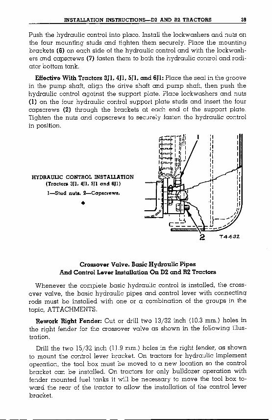
EffectiveWith Tractors 3J1.4J1.SJ1.and 6JI: Place the seal in the groovein the pump shaft, align the drive shaft and pump shaft, then push thehydraulic control against the support plate. Place lockwashers and nuts(1) on the four hydraulic control support plate studs and insert the fourcapscrews (2) through the brackets at each end of the support plate.Tighten the nuts and capscrews to securely fasten the hydraulic controlin position.
•
.....-I1......,j1...-- ......,,111/11+--='1' I II!.I1'1---1' I II I"r---Y I II I
1...-:-,. In' J~~,. wi--..Ji.WI
0. 1:1('tl.t...,..~,HYDRAULIC CONTROL INSTALLATION(Tractors 3Jl. 4JI. 5Jl and 6Jl)
I-Stud nuts. 2-Capscrews •
2 T4432.
Crossover Valve, BasicHydraulic PipesAnd ControlLever Installation On D2and R2Tractors
Whenever the complete basic hydraulic control is installed, the crossover valve, the basic hydraulic pipes and control lever with connectingrods must be installed with one or a combination of the groups in thetopic, ATTACHMENTS.
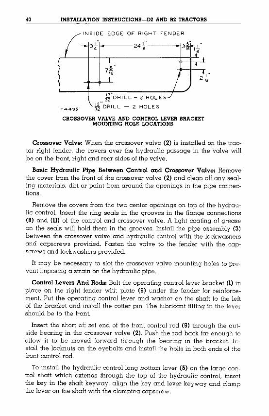
Rework Right Fender: Cut or drill two 13/32 inch 00.3 mm.) holes inthe right fender for the crossover valve as shown in the following illustration.
Drill the two 15/32 inch 01.9 mm.) holes in the right fender, as shownto mount the control lever bracket. On tractors for hydraulic implementoperation, the tool box must be moved to a new location so the controlbracket can be installed. On tractors for only bulldozer operation withfender mounted fuel tanks it will be necessary to move the tool box toward the rear of the tractor to allow the installation of the control leverbracket.
40 INSTALLATION INSTRUCTIONS-D2 AND R2 TRACTORS
INSIDE EDGE OF RIGHT FENDER
I"3t~----24i6 ------.4
T4495
~rDRILL-2 HOLES
~rDRILL - 2 HOLES
CROSSOVER VALVE AND CONTROL LEVER BRACKETMOUNTING HOLE LOCATIONS
Crossover Valve: When the crossover valve (2) is installed on the tractor right fender, the covers over the hydraulic passage in the valve willbe on the front, right and rear sides of the valve.
Basic Hydraulic Pipe Between Control and Crossover Valve: Removethe cover from the front of the crossover valve (2) and clean offany sealing materials, dirt or paint from around the openings in the pipe connections.
Remove the covers from the two center openings on top of the hydraulic control. Insert the ring seals in the grooves in the flange connections(8) and (Il) of the control and crossover valve. A light coating of greaseon the seals will hold them in the grooves. Install the pipe assembly (3)between the crossover valve and hydraulic control with the lockwashersand capscrews provided. Fasten the valve to the fender with the capscrews and lockwashers provided.
It may be necessary to slot the crossover valve mounting holes to prevent imposing a strain on the hydraulic pipe.
Control Levers And Rods: Bolt the operating control lever bracket (l) inplace on the right fender with plate (6) under the fender for reinforcement. Put the operating control lever and washer on the shaft to the leftof the bracket and install the cotter pin. The lubricant fitting in the levershould be to the front.
Insert the short off set end of the front control rod (9) through the outside bearing in the crossover valve (2). Push the rod back far enough toallow it to be moved forward through the bearing in the bracket. Install the locknuts on the eyebolts and install the bolts in both ends of thefront control rod.
To install the hydraulic control long bottom lever (S) on the large control shaft which extends through the top of the hydraulic control. insertthe key in the shaft keyway, align the key and lever keyway and clampthe lever on the shaft with the clamping capscrew.
INSTALLATION INSTRUCTIONS-D2 AND R2 TRACTORS
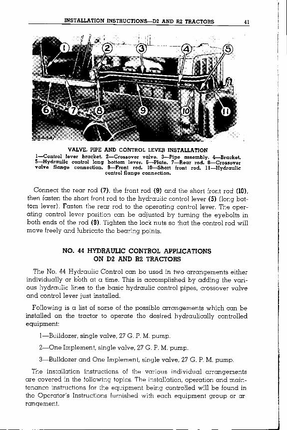
VALVE, PIPE AND CONTROL LEVER INSTALLATIONI-Control lever bracket. 2-Crossover valve. 3-Pipe assembly. 4-Bracket.5-Hydraulic control long bottom lever. 6-Plate. 7-Rear rod. 8-Crossovervalve flange connection. 9-Front rod. IO-Short front rod. II-Hydraulic
control flange connection.
Connect the rear rod (7), the front rod (9) and the short front rod (10),then fasten the short front rod to the hydraulic control lever (5) (long bottom lever). Fasten the rear rod to the operating control lever. The operating control lever position can be adjusted by turning the eyebolts inboth ends of the rod (9). Tighten the lock nuts so that the control rod willmove freely and lubricate the bearing points.
NO. 44 HYDRAULIC CONTROL APPLICATIONSON D2 AND R2 TRACTORS
The No. 44 Hydraulic Control can be used in two arrangements eitherindividually or both at a time. This is accomplished by adding the various hydraulic lines to the basic hydraulic control pipes, crossover valveand control lever just installed.
Following is a list of some of the possible arrangements which can beinstalled on the tractor to operate the desired hydraulically controlledequipment:
I-Bulldozer, single valve, 27G. P.M.pump.
2-0ne Implement,single valve, 27G. P.M.pump.
3-Bulldozer and One Implement,single valve, 27G. P.M.pump.
The installation instructions of the various individual arrangementsare covered in the followingtopics. The installation, operation and maintenance instructions for the equipment being controlled will be found inthe Operator's Instructions furnished with each equipment group or arrangement.
41
42 INSTALLATION INSTRUCTIONS-D2 AND R2 TRACTORS
The hydraulic control is designed to operate with any double actingcylinders of limited dimensions. The use of single acting cylinders is notrecommended since damage to the control may result.
ATTACHMENTSCross Pipe Installation On D2 and R2 Tractors
This group can be installed on the tractor after the installation of thebasic hydraulic pipe and control lever as instructed in the topic, CROSSOVERVALVE,BASICHYDRAULICPIPEANDCONTROLLEVERINSTALLATION.Remove the cover from the right side of the crossover valve and clean
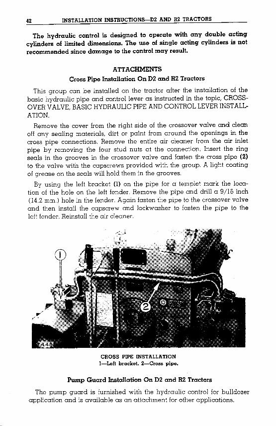
off any sealing materials, dirt or paint from around the openings in thecross pipe connections. Remove the entire air cleaner from the air inletpipe by removing the four stud nuts at the connection. Insert the ringseals in the grooves in the crossover valve and fasten the cross pipe (2)to the valve with the capscrews provided with the group. A light coatingof grease on the seals will hold them in the grooves.By using the left bracket (1) on the pipe for a templet mark the loca
tion of the hole on the left fender. Remove the pipe and drill a 9/16 inch04.2 mm.) hole in the fender. Again fasten the pipe to the crossover valveand then install the capscrew and lockwasher to fasten the pipe to theleft fender. Reinstall the air cleaner.
CROSS PIPE INSTALLATIONI-Left bracket. 2-Cross pipe.
Pump Guard Installation On D2 and R2 Tractors
The pump guard is furnished with the hydraulic control for bulldozerapplication and is available as an attachment for other applications.

INSTALLATION INSTRUCTIONS-D2 AND R2 TRACTORS 43
PUMP GUARD INSTALLATION(Tractors 4Ul and SUI Up)
l-Capscrews. 2-Capscrew inmounting bracket .
•
EHective With Tractors 4Ul and SUI: Remove the capscrews whichhold the radiator screen to the radiator top tank and raise the pumpguard into position. Insert the capscrews (1) through the top of the guard,spacer and screen, then fasten them securely to the radiator top tank.Insert the screws (2) through the side of the guard into the mountingbrackets and tighten them.
Effective With Tractors 3JI, 4JI, 5JI, and 6JI: Install the two pump guardtop support brackets (3) on the sides of the tractor. Fasten the bracketssecurely using the four capscrews (4) provided for each side.
Raise the pump guard (6) into position and insert the capscrewsthrough the holes in the sides of the guard and into the hydraulic control support plate and tighten them. Install the two capscrews (5) througheach top support bracket and fasten the guard securely.
PUMP GUARD TOP SUPPORTBRACKET INSTALLATION
(Tractors 3Jl. 4J1. 511 and 6Jl Up)
3-Support bracket. 4-Capscrew holdingbracket. 5-Capscrew holding guard. 3
6-Pump guard. ~_....L... ....L.__ -..
•

44 INSTALLATION INSTRUCTIONS-D2 AND R2 TRACTORS
Bulldozer or Two Implement Hydraulic Surge TankGroup Installation on D2 Tractors
The hydraulic surge tank is used to increase the oil capacity and provide sufficient air cavity to protect the hydraulic control from damagewhenever either Bulldozer or Two Implement arrangement is used. Thisclosed hydraulic system must have an air cavity large enough to accomodate oil displaced by the cylinder rods.
STARTING ENGINE EXHAUST 1r 9f. .9~1~.. !_>"DRILL •.~_ 16 I:: HOLES 12~
r:-' "".,1-0- r I51'+---·-t--·~---r- j__ _j~. ._.~LE TO BE CUT _
I 213 "'-----2 I R I"N iii ,4~ 17*4---5f._. ~ - 1::---+--1"' . -1;--1
1.__ ':'";:6"2 7~~ ~]----<>-
O----DIESEL ENGINE EXHAUST
FRONT EDGE OF HOOD~Tl"O~9
HYDRAULIC SURGE TANK MOUNTING HOLE LOCATIONS
Rework Tractor Hood: Remove the hood. Layout and cut holes as instructed in the illustration.Tank Installation: Install the tank (1) on top of the hood and fasten it,
with the reinforcing plate (2), on the bottom side of the hood, with thebolts, lockwashers and nuts provided. Clean off any sealing materials,dirt or paint fromaround the openings in the pipe connections. Insert thering seal (3) in the groove in the flange of the tank and fasten the upperpipe (4) to the flange with the lockwashers and capscrews provided.Install and clamp hose (5) to the upper pipe.
HYDRAULIC SURGE TANK INSTALLATIONI-Tank. 2-Reinforcing plate. 3-Seal. 4-Upper pipe.
S-Hose. 6-Lower pipe.

INSTALLATION INSTRUCTIONS-D2 AND R2 TRACTORS 45
Install the hood with tank, on the tractor being careful to prevent dirtentering the hydraulic oil passage.
Remove the cover from the top left opening of the hydraulic controland clean off any sealing material, dirt or paint from around the openings in the lower pipe connection. Install the lower pipe (6) in the hoseand fasten the pipe to the hydraulic control with lockwashers and capscrews provided with the hydraulic control. Be sure the gasket betweenthe lower pipe and hydraulic control will properly seal the hydraulic system oil. Clamp the hose to the lower pipe.
One ImplementGroup Installation On D2 and R2 Tractors
Remove the cover from the rear of crossover valve (3) and clean anysealing materiaL dirt or paint from around the openings in the pipe connections. Insert the ring seals in the grooves in the crossover valve body.A light coating of grease on the seals will hold them in position. Lift thehydraulic implement pipe assembly (2) to the fender and fasten it to thecrossover valve with the capscrews and lockwashers provided. Use thebracket (1) as a templet for locating the mounting holes in the right fender. Drill two 13;32 inch (10.3mm.) holes in the fender and fasten thepipe assembly with the bolts, lockwashers and nuts provided.
ONE IMPLEMENT PIPE ASSEMBLY INSTALLATIONI-Bracket. 2-Pipe assembly. 3-Crossover valve .
•

46
Lubrication InstructionsGENERAL LUBRICATION INFORMATION
Detailed instructions regarding the lubrication of the hydraulic controlare given in the lubrication chart and in the illustrations following. Thelubrication chart specifies the points to be serviced, the hourly intervalsand the type of lubricant to be used. Hourly intervals are to be interpreted as those recorded on the "Hour Meter" of the tractor. The hoursindicated are for normal service. For operating conditions of extremewater, dust and mud lubricate more frequently where hydraulic fittingsare used. Clean the fittings before lubricating so that dirt will not becarried in with the lubricant.
Careful attention to the following information on lubricants and theirproper selection will add much to performance, economy and long lifeof the hydraulic control.
When checking and refilling the hydraulic control, do so with thetractor on level ground.
Use the brush supplied in the tractor tool equipment when removingdirt from fittings and when cleaning around the filleropening and covers.Lubricate all miscellaneous points, not equipped with fittings,with crankcase lubricating oil every 60hours.
The following topics recommend the types, viscosities and grades oflubricants best suited for use in the hydraulic control for various operating temperatures. The S.A.E. (Society of Automotive Engineers) andN.L.G.I.(National Lubricating Grease Institute) numbers refer only to theviscosity or consistency of the lubricant and have reference to no othercharacteristic or property.
CRANKCASE LUBRICATING OIL(Abbreviated CO)
(CO) Use either Superior Lubricants (Series 2) or an oil conforming tothe requirements of MIL-L-2l04Aspecification in the hydraulic controltank.
The oil in the hydraulic system should be fluid enough to flow freelyat the lowest temperature at which the engine will be started in orderto insure maximum service life from the hydraulic system. For this reasonuse S.A.E. No. lOW oil for temperatures above 0° F. For temperaturesbelow 0° F. dilute the oil with kerosene up to 251'0 so it will be fluidenough to insure free circulation.
Naturally, any precautions taken during cold weather to keep thetractor and hydraulic system warm will reduce the need for diluting thehydraulic system oil.

47A
"lEG.U,S, PAT.0,.".
LUBRICATION CHARTCATERPILLAR
No. 44HYDRAULIC CONTROL
The folded page is arranged to serve two purposes:
First, it is a complete outline of all the informationrequired to lubricate the hydraulic control.
Second, the illustration and identification of points oflubrication can be used with the detailed illustrationsand information on the pages following the chart as areference for lubrication and service information.
CO Crankcase lubricating Oil ilK lIall and Koller lIearlng LUOrlcant
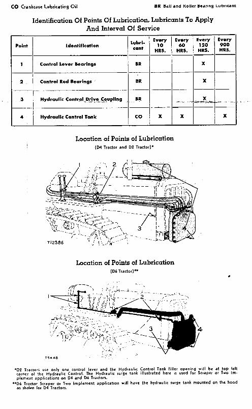
Identification Of Points Of Lubrication, Lubricants To ApplyAnd Interval Of Service
Point Identification Lubricant
Every I Every Every Every10 60 120 900
HRS. HRS. HRS. HRS.1---1·------------11------ -------
x---1------------- --- --- ---------
Hydraulic ContrC)U),~,..!'!~_._C.,~o..,u.pling BR X--' -' -I---·"·"-····-"'''-~·-',..··'-I···Hydraulic Control Tank CO X X X .
Control Lever Bearings BR x
BR2 Control Rod Bearings
.3
4
Location of Points of Lubrication(04 Tractor and 02 Tractor)·
Location of Points of Lubrication(06 Tractor)··
~1?~:~~~'~;~1i;{>.c~','f
.02 Tractors use only one control lever and the Hydraulic Control Tank filler opening will b. at top leftcorner 01 the Hydraulic Conlrol. The Hydraulic surge tank illuslrated here is used for Scraper or Two lmplement applicalions on 04 and 06 Tractors .
•• 06 Tracter Scraper or Two Implement applicalion will have the hydraulic surge lank mounled on the hoodas shown for 04 Tractors.
co Crankcase Lubricating Oil
vATERpIl.t,A
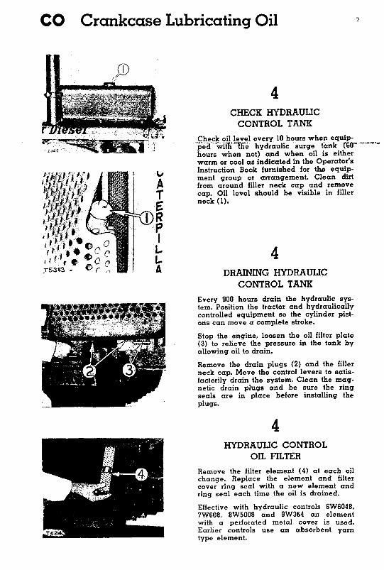
4CHECK HYDRAUUCCONTROL TANK
Check oil level every 10hours when equip-'ped -\vHf{ 'tile hydraulic surge tank (SII =.~,,,..,,,hours when not) and when oil is eitherwarm or cool as indicated in the Operator'sInstruction Book furnished for th.e equip-ment group or arrangement. Clean dirtfrom around filler neck cap and removecap. Oil level should be visible in fillerneck 0).
4DRAINING HYDRAUUC
CONTROL TANKEvery 900 hours drain the hydraulic system. Position the tractor and hydraulicallycontrolled equipment so the cylinder pistons can move a complete stroke.
Stop the engine. loosen the oil filter plate(3) to relieve the pressure in the tank byallowing oil to drain.
Remove the drain plugs (2) and the fillerneck cap. Move the control levers to satisfactorily drain the system. Clean the magnetic drain plugs and be sure the ringseals are in place before installing theplugs.
4HYDRAUUC CONTROL
OIL FILTERRemove the filter element (4) at each oilchange. Replace the element and filtercover ring seal with a new element andring seal each time the oil is drained.
Effective with hydraulic controls 6W6048.7W608. 8W5008 and 9W364 an elementwith a perforated metal cover is used.Earlier controls use an absorbent yamtype element.
LUBRICATION INSTRUCTIONS 47
Hydraulic oil should be drained and replaced with undiluted S.A.E.No. lOWoil at the end of the cold season when dilution of the oil is nolonger required.
It is extremely important in handling the oil to keep it clean. Everyprecaution should be taken to use only clean filler cans and to be surethat all dirt is removed from the filler cap for the hydraulic control beforeit is taken off for filling.
Careful attention was given to the design of the hydraulic system toguard against oil leaks. Connections were eliminated where possibleand metal to metal joints, with rubber ring seals, are used instead of theusual pipe thread joints.
Oil leaks should not be neglected as the loss of oil is an unnecessaryexpense as well as a possible cause of damage to the hydraulic system.
The operator should take every precaution to prevent dirt getting intothe hydraulic system to extend the life of the hydraulic pump.
BALL AND ROLLER BEARING LUBRICANT(Abbreviated BR)
(BR)This lubricant is a mixture of mineral oil and metallic soaps. UseNo.2 grade for most temperatures. For extremely low temperatures useNo. 0 or No. 1 grade.
This grease can be applied to all bearing points - plain bushings,ball bearings and roller bearings-where equipped with hydraulic pressure fittings or when bearings are hand packed.
Use only a high grade Ball and Roller Bearing Grease of short fiber.This grease must be satisfactory in anti-friction bearings at speeds upto 3000RPMat a maximum temperature of 3000 F. It is a grease withsufficient adhesive qualities to cling to the bearings in all extremes ofhigh and low operating temperatures. Greases of this kind have beenclassified by grades by the N.L.G.I.(National Lubricating Grease Institute) designated in order of "worked" penetration or consistency.
LUBRICATION INSTRUCTIONS 49
co Crankcase Lubricating Oil
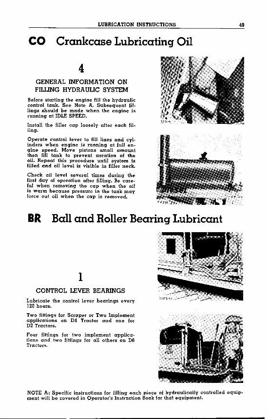
4GENERAL INFORMATION ONFILLING HYDRAULIC SYSTEM
Before starting the engine fill the hydrauliccontrol tank. See Note A. Subsequent fillings should be made when the engine isrunning at IDLESPEED.
Install the filler cap loosely after each filling.
Operate control lever to fill lines and cylinders when engine is running at full engine speed. Move pistons small amountthen fill tank to prevent aeration of theoil. Repeat this procedure until system isfilled and oil level is visible in filler neck.
Check oil level several times during thefirst day of operation after filling. Be careful when removing the cap when the oilis warm because pressure in the tank mayforce out oil when the cap is removed.
BR Ball and Roller Bearing Lubricant
1CONTROL LEVER BEARINGS
Lubricate the control lever bearings every120hours.
Two fittings for Scraper or Two Implement.applications on 04 Tractor and one for02 Tractors.
Four fittings for two implement applications and two fittings for all others on 06Tractors.
NOTE A: Specific instructions for Jilling each piece of hydraulically controlled equipment will be covered in Operator's Instruction Bookfor that equipment.
50 LUBRICATIONINSTRUCTIONS
BR Ball and Roller Bearing Lubricant
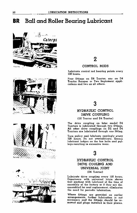
2CONTROL RODS
Lubricate control rod bearing points every120hours.
Four fittings on 06 Tractor, one on 04Tractor Scraper or Two Implement applications and two on all others.
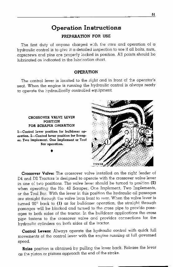
3HYDRAULIC CONTROL
DRIVE COUPLING(02 Tractor and 04 Tractor)
The drive coupling on later model 04Tractors is lubricated through two fittings.All other drive couplings on 02 and 04Tractors are lubricated through one fitting.
Turn pulley and lubricate sparingly every120 hours. 00 not overlubricate. Excesslubricant lodges on the fan belts and pulleys resulting in excessive wear.
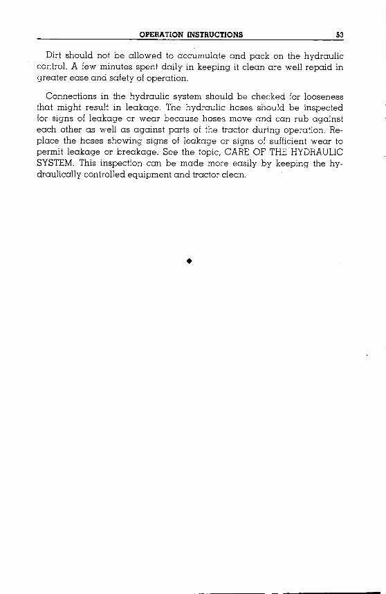
3HYDRAULIC CONTROLDRIVE COULING ANDUNIVERSAL JOINT
(06 Tractor)
Lubricate drive coupling every 120 hours.Experience with universal joints showsthat packing with lubricant at the time ofassembly at the factory or if they are disassembled for seal replacement, eliminatesthe need for periodic lubrication.
Where fittings are provided on earlierarrangements, further lubrication is notnecessary and the fittings should be removed and plugs installed in their places.
51
Operation InstructionsPREPARATION FOR USE
The first duty of anyone charged with the care and operation of ahydraulic control is to give it a detailed inspection to see if all bolts, nuts,capscrews and pins are properly locked in position. All points should belubricated as indicated in the lubrication chart.
OPERATION
The control lever is located to the right and in front of the operator'sseat. When the engine is running the hydraulic control is always readyto operate the hydraulically controlled equipment.
CROSSOVER VALVE LEVERPOSITION
FOR SCRAPER OPERATION
I-Control lever position for bulldozer operation. 2-Control lever position for Scraper, Two Implement, One Implement or Tool
Bar operation .
•
Crossover Valve: The crossover valve installed on the right fender ofD4 and D2Troctors is designed to operate with the crossover valve leverin one of two positions. The valve lever should be turned to position (2)when operating the No. 40 Scraper, One Implement, Two Implements,or the Tool Bar. With the lever in this position the hydraulic oil passagesare straight through the valve from front to rear. When the valve lever isturned 90° back to (1) as for bulldozer operation, the straight throughpassages will be blocked and turned to the cross pipe to provide passages to both sides of the tractor. In the bulldozer applications the crosspipe fastens to the crossover valve and provides connections for thehydraulic cylinders on both sides of the tractor.
Control Levers: Always operate the hydraulic control with quick fullmovements of the control lever with the engine running at full governedspeed.
Raise position is obtained by pulling the lever back. Release the leveras the piston or pistons approach the end of the stroke.

52 OPERATION INSTRUCTIONS
HYDRAULIC CONTROL LEVER POSITIONS
The cylinder piston can be held in any position, by releasing the control lever and allowing it to return to the neutral or hold position. It isnecessary to pull the control lever out of float position then release it toallow it to return to neutral or hold position.
Lower position is obtained by pushing the control lever forward untilresistance is felt in the control lever.
Release the control lever when the piston or pistons have reached thelimit of their strokes to stop the oil by-passing the valves and also toreduce heat and wear.
Float position is obtained by pushing the control lever forward throughlower position. At this point, a noticeable resistance will be felt on thelever. Continue to push it forward to the float position. The control leverwill remain in float position until it is pulled back and released to returnto the hold or neutral position.
Float position is available in only one valve of a double valve hydraulic control or in all single valve controls.
DAILY CARE
A daily check of the hydraulic control should be made to see if thereare any loose nuts, bolts, capscrews, or parts worn to such an extentthat they are no longer serviceable. If corrective steps are taken immediately upon discovery of loose or worn parts, fewer forced stops andmore economical operation will result.
OPERATION INSTRUCTIONS 53
Dirt should not be allowed to accumulate and pack on the hydrauliccontrol. A few minutes spent daily in keeping it clean are well repaid ingreater ease and safety of operation.
Connections in the hydraulic system should be checked for loosenessthat might result in leakage. The hydraulic hoses should be inspectedfor signs of leakage or wear because hoses move and can rub againsteach other as well as against parts of the tractor during operation. Replace the hoses showing signs of leakage or signs of sufficient wear topermit leakage or breakage. See the topic, CAREOF THEHYDRAULICSYSTEM.This inspection can be made more easily by keeping the hydraulically controlled equipment and tractor clean .
•

54
Maintenance Instructions"Caterpillar" Hydraulic Controls have been constructed so that very
few adjustments are necessary. If they are properly maintained they willgive an unlimited amount of trouble free service. Maintenance and careof the hydraulic system will be covered in the following topics.
CARE OF THE HYDRAULIC SYSTEM
The hydraulic system is designed so that no adjustments are necessary. There are, however, a few precautionary measures which should befollowed. Cleanliness is of great importance in the hydraulic system andgreat care should be taken to keep dirt out.
Check the oil every 10hours in Two Implement or Scraper applicationsand fillwith oil ii necessary. If the oil is low, make a thorough inspectionof the hoses and connections for leaks. It should not be necessary to addoil if all the connections are tight and the hoses are in good condition.See the LUBRICATIONINSTRUCTIONSfor type of oil, general draining,filter replacement and general fillingof the hydraulic system.
Details of draining and filling the hydraulic system will be found inthe Operator's InstructionBookfor the controlled equipment.
The control levers and rods should be in correct adjustment at all timesto prevent partial opening or closing of the control valves. The controllever should always operate freely and return to the "hold" position byspring action when released from either "raised" or "lower" position.
Hose Replacement: Check the hose daily for any signs of leakageor wear. Do not wait for actual breakage before replacing the hoses.Check the hose clamps frequently after installing new hoses, to makecertain they are tight. A loose clamp could cause a separation of the hosefrom the sleeve. The loss of hydraulic system oil, due to a broken hose,will cause unnecessary loss of time as well as damage to the hydrauliccontrol.
Remove the hose by disconnecting the flange connections at the cylinder and the pipe assembly or crossover valve. Cap all openings of thehydraulic system when the hoses are removed. Remove the clamp (2) andcut half way around the hose at a 45° angle fromthe end of the hose untilit can be removed from the stem (4). It is necessary to cut only the wirebraids in the hose. Cut the hose with an 18teeth to the inch hack saw byusing short choppy strokes. Lift the blade slightly on the return stroke.
If the stem is cut or burrs are noticed, remove the burrs or replace thestem with a new one. Replace the hose with new % inch (l.90 cm.) twowire braid high pressure hydraulic hose the same length as the one beingreplaced. Clean the cuttings from the hose before installing the stem.
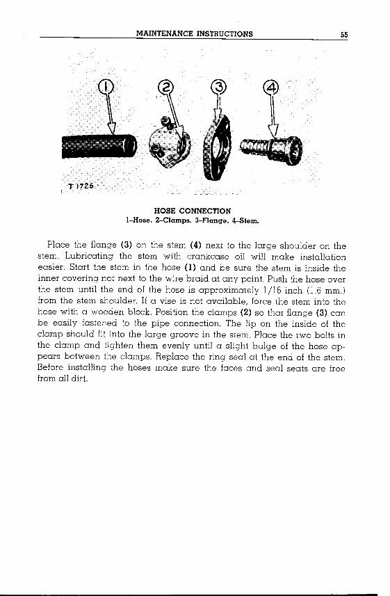
MAINTENANCE INSTRUCTIONS 55
HOSE CONNECTIONI-Hose. 2-Clamps. 3-Flange. 4-Slem.
Place the flange (3) on the stem (4) next to the large shoulder on thestem. Lubricating the stem with crankcase oil will make installationeasier. Start the stem in the hose (1) and be sure the stem is inside theinner covering not next to the wire braid at any point. Push the hose overthe stem until the end of the hose is approximately 1/16 inch (1.6mm.)from the stem shoulder. If a vise is not available, force the stem into thehose with a wooden block. Position the clamps (2) so that flange (3) canbe easily fastened to the pipe connection. The lip on the inside of theclamp should fit into the large groove in the stem. Place the two bolts inthe clamp and tighten them evenly until a slight bulge of the hose appears between the clamps. Replace the ring seal at the end of the stem.Before installing the hoses make sure the faces and seal seats are freefromall dirt.

56
PageAttachments-06 Tractor 13Attachments-04 Tractor 27Attachments-02 and R2 Tractors 42
Ball and Roller BearingLubricant
Basic Hydraulic Pipes andControl Lever Installationon 06 Tractor ...
Bulldozer Crosspipe Installationon 04 Tractor ....on 02 and R2 Tractors
Bulldozer or Two ImplementHydraulic Surge Tank GroupInstallation on 02 Tractors
Capacities ... Inside BackCare of the Hydraulic SystemCrankcase Lubricating Oil ..Crossover Valve, BasicHydraulic Pipes and ControlLever Installation on04 Tractors02 and R2 Tractors
Oaily Care ...Orive Coupling Installationon D6 Tractorson 04 Tractorson 02 and R2 Tractors
General Lubricating Information
Hose Replacement ...Hydraulic Control Installationon 06 Tractorson 04 Tractorson 02 and R2 Tractors
Hydraulic System, Care of the
Installation Instructions-GeneralInstallation on 06 Tractor-Part One
Installation on 04 TractorPart Two ..
Installation on 02 and R2Tractors-Part Three
Introduction
Lubrication ChartLubrication InstructionsLubrication of MiscellaneousPoints
FORM 12761-3
Cover5446
354
47A46
Index
47
Maintenance InstructionsMounting Group and HydraulicControl Installation-06 Tractor
Mounting Group and HydraulicControl Installation-04 Tractor
Mounting Group and HydraulicControl Installation-02 and R2 Tractors ....9
2742
No. 44 Hydraulic ControlApplications on 06 TractorApplications on 04 TractorsApplications on 02and R2 Tractors .
No. 64 Tool Bar Lines GroupInstallation on 04 Tractors.
44
2439
52
One Implement Group Installationon 06 Tractoron 04 Tractoron 02 and R2 Tractors
OperationOperation Instructions
Preparation for UsePump Guard Installation on04 Tractors02 and R2 Tractors7
2035
46
54
Radiator Screen GuardReworking for 02 Tractors
Reinstall the Radiator on04 Tractors
8233854
5
Scraper on Two ImplementMounting Group Installationon 04 Tractors
Scraper or Two ImplementHydraulic Surge Tank GroupInstallation on 04 Tractors
Serial Number7
Page54
7
20
35
1226
41
29
1333455151
51
2842
37
22
30
Location Inside Back Cover
32
Tool Bar Line Group Installa-tion on 06 Tractor . . . 19
Two Implement or ScraperHydraulic Surge Tank GroupInstallation on 06 Tractor 18
Two Implement or ScraperMounting Group Installation on 06 Tractor ...
20
46 15
9-54PRINTED IN U.S.A.

CapacitiesApproximate Quantities
No. 44 Hydraulic:Control (Front Mounted) 31/2gal.See the Operator's Instruction Book furnished with each equipment
group or arrangement for fullcapacity of the hydraulic system.
Serial No. Valves B.P.M. G.P.M. P.8.L
6W5001 I 1400 37 1000
7Wl 2 1400 37 1000
8W5001 2 1400 25 1000
9Wl (D4) 1 1400 25 1000
9Wl (D2) 1 1525 27 1000
•Location Of Serial Number
«''<'
FORM 12761-3
CATERPILLAR TRACTOR CO.PEORIA, ILLINOIS,U.S.A.
Diesel Engines •• Tractors •• Motor Graders• • • • • Earthmoving Equipment • • •• '.
THERE IS A "CATERPILLAR" DEALERNEAR YOU
PRINTED IN U.S.A.