Embed Size (px)
Citation preview
-23-
Hydraulic BrakesDexter offers several varieties of hydraulic trailer brakes. Your vehicle may be equipped with drum brakes or disc brakes.
The hydraulic brakes on your trailer are much like those on your automobile or light truck. The hydraulic fluid from a master cylinder or actuation system is used to actuate the wheel cylinder which, in turn, applies force against the brake shoes and drum. The main difference between automotive hydraulic brakes and hydraulic trailer brakes is the trailers’ actuation system. These systems respond to the braking signal from the tow vehicle and supply the required brake fluid volume and pressure to the trailer brakes.
In the following pages you will find a more detailed description of the hydraulic brakes and actuation system used on your trailer.
CAUTIONThe maximum operating pressure for Dexter brakes:• 7" diameter drum brakes maximum operating pressure is 750 psi• 10" diameter and larger drum brakes maximum operating pressure is 1,000 psi• Hydraulic disc brakes (all sizes) maximum operating pressure is 1,600 psi
Braking Systems - Hydraulic
10-13
-24-
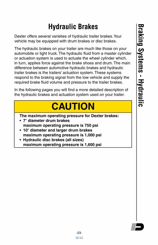
Hydraulic Drum Brake OperationDuo-ServoThe duo-servo brake uses a dual piston wheel cylinder to apply the brakes. This type of brake is typically used in an electric/hydraulic, vacuum/hydraulic, or air/hydraulic system. A description of operation of this brake is as follows:
When the brakes are applied, the double-acting wheel cylinder moves the primary and secondary shoes towards the drum. The frictional force between the brake drum and lining attempts to turn the primary shoe into the secondary shoe. The secondary shoe is forced onto the anchor pin and from this point, the secondary and primary shoes attempt to “wrap around”. In essence, the brake has utilized frictional force to help the applying force on both shoes.
If the brakes are applied while the vehicle is backing, the shoes rotate in the direction of the drum rotation. This causes the secondary shoe to leave the anchor and causes the primary shoe to move against the anchor. Action of the brake is the same in reverse as forward.
Uni-ServoThis type of hydraulic brake utilizes a single acting cylinder. Upon actuation, the primary shoe is pressed against the brake drum, which causes the shoe to move in the direction of rotation. This movement in turn actuates the secondary shoe through the adjuster assembly. Braking in reverse is significantly less effective than in the forward direction.Br
akin
g Sy
stem
s - H
ydra
ulic
Anchor Post
Retractor Springs
Backing Plate
Secondary Shoe
Adjuster SpringAdjuster Assembly
Primary Shoe
Hold Down Spring
Actuating Pin
Hydraulic Wheel Cylinder
10-13
-25-
Braking Systems - Hydraulic
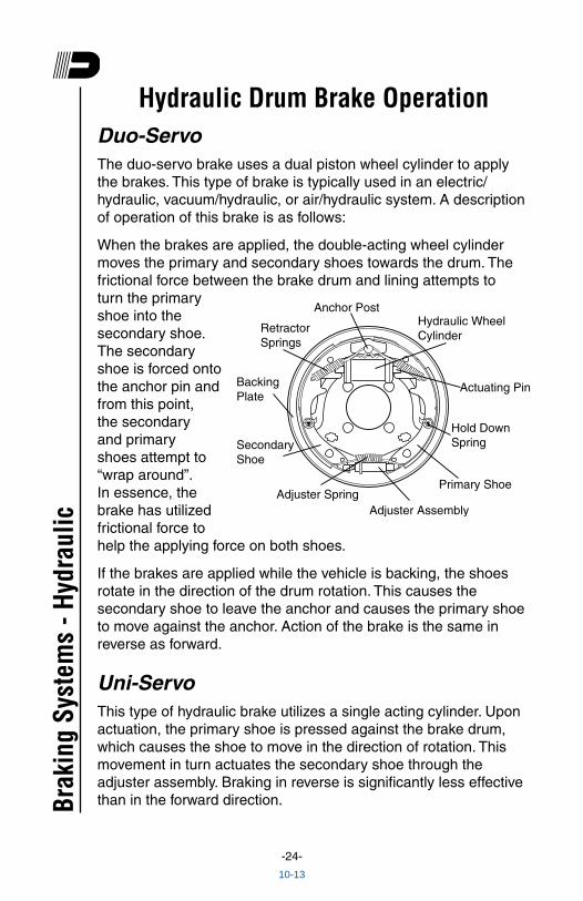
Another variation is called a “free backing” brake which is commonly used on trailers with a surge hitch system. When backing with a surge brake hitch, normal brakes are applied through the surge mechanism and if there is more brake force on the trailer than the tow vehicle can override, no backing is possible. The free backing brake was developed to allow backing in this application. This brake has a primary shoe on a pivot which allows normal application in the forward direction, but allows the primary shoe to rotate away from the drum surface when backing.
Self Adjusting Mechanism for 12¼" Hydraulic BrakesForward self-adjust hydraulic brakes were introduced in March of 1997. This feature adjusts the brakes on both forward and reverse stops. Brake adjustment occurs only when lining wear results in enough gap between the shoes and the drum surface. This added clearance will allow the adjuster mechanism to rotate the screw assembly at the bottom of the brake. That action expands the distance between the shoes and thus closes the gap to the drum surface.
Hydraulic Parking Brake Option (Not available on all sizes)
The parking feature on Dexter hydraulic brakes is cable operated. On the 10" and 12" brakes, the parking cable body is mounted to the brake backing plate. The cable end is attached to the internal parking brake lever to actuate the brake. On Dexter 12¹⁄₄" brakes manufactured before February of 2002, the parking cable body
Anchor Post
Retractor Springs
Backing Plate
Secondary Shoe
Adjuster SpringAdjuster Assembly
Primary Shoe
Hold Down Spring
Actuating Pin
Hydraulic Wheel Cylinder
10-13
-26-
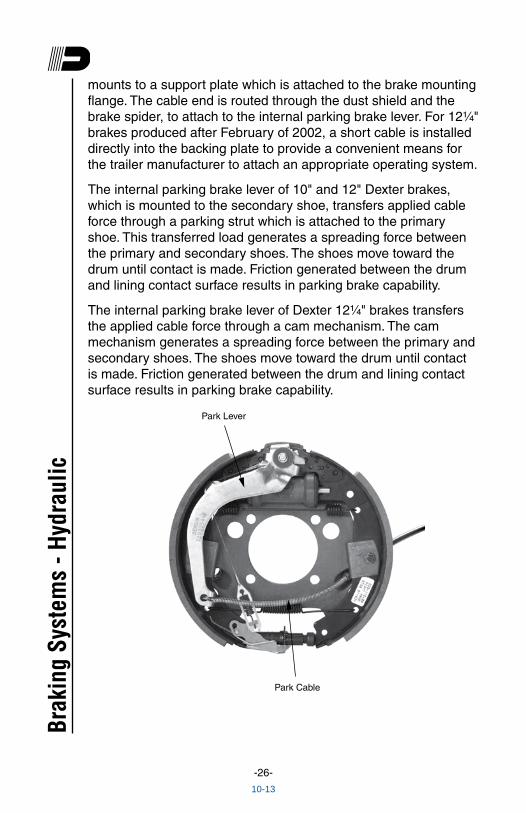
mounts to a support plate which is attached to the brake mounting flange. The cable end is routed through the dust shield and the brake spider, to attach to the internal parking brake lever. For 12¹⁄₄" brakes produced after February of 2002, a short cable is installed directly into the backing plate to provide a convenient means for the trailer manufacturer to attach an appropriate operating system.
The internal parking brake lever of 10" and 12" Dexter brakes, which is mounted to the secondary shoe, transfers applied cable force through a parking strut which is attached to the primary shoe. This transferred load generates a spreading force between the primary and secondary shoes. The shoes move toward the drum until contact is made. Friction generated between the drum and lining contact surface results in parking brake capability.
The internal parking brake lever of Dexter 12¹⁄₄" brakes transfers the applied cable force through a cam mechanism. The cam mechanism generates a spreading force between the primary and secondary shoes. The shoes move toward the drum until contact is made. Friction generated between the drum and lining contact surface results in parking brake capability.
Park Cable
Park Lever
Brak
ing
Syst
ems
- Hyd
raul
ic
10-13
-27-
Braking Systems - Hydraulic
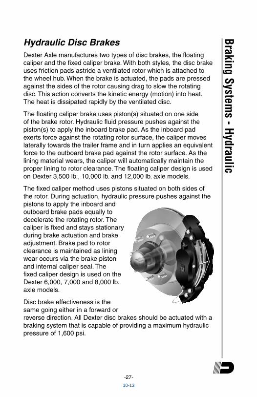
Hydraulic Disc BrakesDexter Axle manufactures two types of disc brakes, the floating caliper and the fixed caliper brake. With both styles, the disc brake uses friction pads astride a ventilated rotor which is attached to the wheel hub. When the brake is actuated, the pads are pressed against the sides of the rotor causing drag to slow the rotating disc. This action converts the kinetic energy (motion) into heat. The heat is dissipated rapidly by the ventilated disc.
The floating caliper brake uses piston(s) situated on one side of the brake rotor. Hydraulic fluid pressure pushes against the piston(s) to apply the inboard brake pad. As the inboard pad exerts force against the rotating rotor surface, the caliper moves laterally towards the trailer frame and in turn applies an equivalent force to the outboard brake pad against the rotor surface. As the lining material wears, the caliper will automatically maintain the proper lining to rotor clearance. The floating caliper design is used on Dexter 3,500 lb., 10,000 lb. and 12,000 lb. axle models.
The fixed caliper method uses pistons situated on both sides of the rotor. During actuation, hydraulic pressure pushes against the pistons to apply the inboard and outboard brake pads equally to decelerate the rotating rotor. The caliper is fixed and stays stationary during brake actuation and brake adjustment. Brake pad to rotor clearance is maintained as lining wear occurs via the brake piston and internal caliper seal. The fixed caliper design is used on the Dexter 6,000, 7,000 and 8,000 lb. axle models.
Disc brake effectiveness is the same going either in a forward or reverse direction. All Dexter disc brakes should be actuated with a braking system that is capable of providing a maximum hydraulic pressure of 1,600 psi.
10-13
-28-
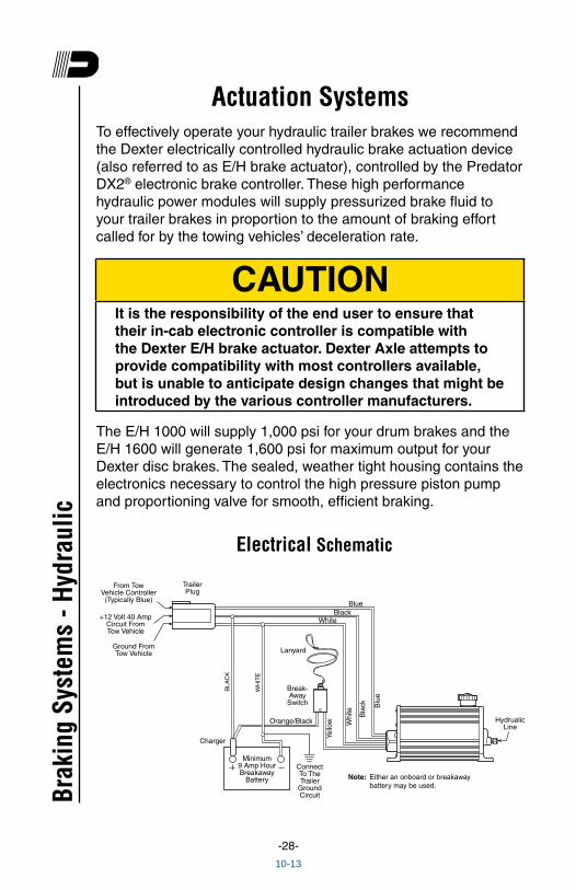
Actuation SystemsTo effectively operate your hydraulic trailer brakes we recommend the Dexter electrically controlled hydraulic brake actuation device (also referred to as E/H brake actuator), controlled by the Predator DX2® electronic brake controller. These high performance hydraulic power modules will supply pressurized brake fluid to your trailer brakes in proportion to the amount of braking effort called for by the towing vehicles’ deceleration rate.
CAUTIONIt is the responsibility of the end user to ensure that their in-cab electronic controller is compatible with the Dexter E/H brake actuator. Dexter Axle attempts to provide compatibility with most controllers available, but is unable to anticipate design changes that might be introduced by the various controller manufacturers.
The E/H 1000 will supply 1,000 psi for your drum brakes and the E/H 1600 will generate 1,600 psi for maximum output for your Dexter disc brakes. The sealed, weather tight housing contains the electronics necessary to control the high pressure piston pump and proportioning valve for smooth, efficient braking.
TrailerPlug
From TowVehicle Controller(Typically Blue)
+12 Volt 40 AmpCircuit FromTow Vehicle
Ground From Tow Vehicle
Break-Away
Switch
BlueBlack
White
Minimum9 Amp Hour Breakaway
Battery
BLA
CK
WH
ITE
Lanyard
Connect To TheTrailer
GroundCircuit
HydrualicLine
Orange/Black
Yello
w Whi
te Bla
ck Blu
e
Charger
Electrical Schematic
Note: Either an onboard or breakawaybattery may be used.Br
akin
g Sy
stem
s - H
ydra
ulic
10-13
-29-
Scan to view E/H Actuator Installation video
Troubleshooting GuideBrakes are slow to respond
1. Re-bleed the trailer brakes and actuator.
2. If the trailer is equipped with drum brakes, readjust the drum brakes to the brake manufacture’s recommended running clearance.
3. Slow response can be caused by trailer wiring that is too small.
4. For trailers where the E/H brake actuator is located less than 10 feet from the tow vehicle, 12 gage wire is recommended for the black and white wires between the tow vehicle and the E/H brake actuator. All other wires should be a minimum of 16 gauge.
5. For trailers where the E/H brake actuator is located more than 10 feet from the tow vehicle, 10 gage wire is recommended for the black and white wires between the tow vehicle and the E/H brake actuator. All other wires should be a minimum of 16 gauge.
6. Slow response can be caused by improper adjustment of the brake controller. On inertia-based electronic brake controls, adjust the pendulum (inertia sensor) to a more aggressive setting and/or increase the gain setting.
Unit will not run when the ignition is on and the brake pedal is depressed
1. Verify that the trailer and tow vehicle are wired as detailed on the electrical schematic.
2. With the ignition switch on and the brakes not applied, you should have 12-13 volts between the black and white wires on the E/H brake actuator.
Braking Systems - Hydraulic
10-13
-30-
3. Clean and replace the ground between the trailer and the E/H brake actuator.
4. Test operation of the unit using the breakaway test procedure.
Breakaway test procedure - do not leave the breakaway switch pulled for more than two minutes during any of the steps outlined below
1. Pull the breakaway switch on the trailer.
2. If the unit runs and builds pressure, that indicates the actuator is functioning properly. The problem most likely is a defective electronic brake controller in the tow vehicle or defective wiring between the tow vehicle and the E/H brake actuator.
3. If the unit runs but will not build pressure, the problem most likely is a defective solenoid valve in the E/H brake actuator and the actuator should be replaced.
4. If the unit still does not run after the breakaway battery is fully charged, verify that the voltage between the white wire and yellow wire is at least 12 volts.
5. If the voltage is less than 12 volts, either the breakaway switch or the breakaway wiring is defective.
6. If the voltage is greater than 12 volts, the E/H brake actuator should be replaced.
Trailer brakes too aggressive1. Reduce the gain setting on the in-cab electronic brake
controller.
Brak
ing
Syst
ems
- Hyd
raul
ic
10-13
-31-
Braking Systems - Hydraulic
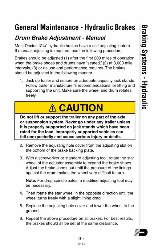
General Maintenance - Hydraulic BrakesDrum Brake Adjustment - ManualMost Dexter 12¹⁄₄" hydraulic brakes have a self adjusting feature. If manual adjusting is required, use the following procedure:
Brakes should be adjusted (1) after the first 200 miles of operation when the brake shoes and drums have “seated,” (2) at 3,000 mile intervals, (3) or as use and performance requires. The brakes should be adjusted in the following manner:
1. Jack up trailer and secure on adequate capacity jack stands. Follow trailer manufacturer’s recommendations for lifting and supporting the unit. Make sure the wheel and drum rotates freely.
! CAUTIONDo not lift or support the trailer on any part of the axle or suspension system. Never go under any trailer unless it is properly supported on jack stands which have been rated for the load. Improperly supported vehicles can fall unexpectedly and cause serious injury or death.
2. Remove the adjusting hole cover from the adjusting slot on the bottom of the brake backing plate.
3. With a screwdriver or standard adjusting tool, rotate the star wheel of the adjuster assembly to expand the brake shoes. Adjust the brake shoes out until the pressure of the linings against the drum makes the wheel very difficult to turn.
Note: For drop spindle axles, a modified adjusting tool may be necessary.
4. Then rotate the star wheel in the opposite direction until the wheel turns freely with a slight lining drag.
5. Replace the adjusting hole cover and lower the wheel to the ground.
6. Repeat the above procedure on all brakes. For best results, the brakes should all be set at the same clearance.
10-13
-32-
Most of the brake components are very similar to those used in electric brakes, and maintenance is comparable for the hub and drum, shoes and linings, and bearings. Specific maintenance activities are as follows:
Wheel CylindersInspect for leaks and smooth operation. Clean with brake cleaner and flush with fresh brake fluid. Hone or replace as necessary.
Brake LinesCheck for cracks, kinks, or blockage. Flush with fresh brake fluid. Bleed system to remove all air. Replace as necessary.
Shoes and LiningsA simple visual inspection of your brake linings will tell if they are usable. Replacement is necessary if the lining is worn (to within ¹⁄₁₆" or less), contaminated with grease or oil, or abnormally scored or gouged. Hairline heat cracks are normal in bonded linings and should not be cause for concern. When replacement is necessary, it is important to replace both shoes on each brake and both brakes of the same axle. This will help retain the “balance” of your brakes.
! CAUTIONPOTENTIAL ASBESTOS DUST HAZARD! Some older brake linings may contain asbestos dust, which has been linked to serious or fatal illnesses. Certain precautions need to be taken when servicing brakes:1. Avoid creating or breathing dust.2. Avoid machining, filing or grinding the brake linings.3. Do not use compressed air or dry brushing for
cleaning (dust can be removed with a damp brush).
After replacement of brake shoes and linings, the brakes must be re-burnished to seat in the new components. This should be done by applying the brakes 20 to 30 times from an initial speed Br
akin
g Sy
stem
s - H
ydra
ulic
10-13
-33-
of 40 m.p.h., slowing the vehicle to 20 m.p.h. Allow ample time for brakes to cool between applications. This procedure allows the brake shoes to seat in to the drum surface.
HardwareCheck all hardware. Check shoe return spring, hold down springs, and adjuster springs for stretch or wear. Replace as required. Service kits are available.
Instructions for Brake Caliper Kit 3.5K Hydraulic Disc BrakesNotice to BuyerIt is recommended that all brakes be replaced at the same time to ensure balanced braking performance.
Remove the old brake caliper1. Jack up trailer and secure on adequate capacity jack stands.
Follow trailer manufacturers recommendations for lifting and supporting the unit.
! CAUTIONDo not lift or support the trailer on any part of the axle or suspension system. Never go under any trailer unless it is properly supported on jack stands which have been rated for the load. Improperly supported vehicles can fall unexpectedly and cause serious injury or death.
2. Remove the wheel from the hub, leaving the brake exposed.
3. Disable the brake actuation system. Check that the hydraulic system has zero pressure and that the hub and rotor rotate freely.
4. Remove the hose from the caliper, then remove the two caliper mounting bolts. Do not allow the caliper to hang from the hose.
Braking Systems - Hydraulic
10-13
-34-
Installing the new brake caliper1. First, inspect the brake assembly for grooves, flaking,
cracks, heat checking, thickness variation, insufficient rotor thickness, and look to see that the mounting hardware is straight. Replace any component as needed (or desired) per manufacturer recommendations.
2. Install the new caliper assembly. Make sure that the bleed screw points up.
3. Remount the caliper assembly onto the caliper attaching bracket. Ensure that there is thread locking compound on the threads of the new mounting bolts. Torque mounting bolts to 40-50 Ft. Lbs.
Note: Use two lug nuts to secure rotor against the hub face when reassembling the caliper. After the caliper is assembled remove the lug nuts.
4. Reconnect the hose to the elbow adapter on the back of the caliper and torque to 10-12 Ft. Lbs.
5. Reconnect the brake actuation system. Refer to your actuation systems Operation Maintenance Service Manual for proper operation.
6. Bleed and flush brake system per your actuation systems Operation Maintenance Service Manual.
7. Remount the wheel. Refer to your Operation Maintenance Service Manual for proper wheel nut torque procedures.
Instructions for Brake Rotor Kit 3.5K Hydraulic Disc BrakesNotice to BuyerIt is recommended that all brakes be replaced at the same time to ensure balanced braking performance.
Remove the old brake rotor1. Jack up trailer and secure on adequate capacity jack stands.
Follow trailer manufacturers recommendations for lifting and supporting the unit.
Brak
ing
Syst
ems
- Hyd
raul
ic
10-13
-35-
! CAUTIONDo not lift or support the trailer on any part of the axle or suspension system. Never go under any trailer unless it is properly supported on jack stands which have been rated for the load. Improperly supported vehicles can fall unexpectedly and cause serious injury or death.
2. Remove the wheel from the hub, leaving the brake exposed.
3. Disable the brake actuation system. Check that the hydraulic system has zero pressure and that the hub and rotor rotates freely.
4. Remove the two caliper mounting bolts. Do not allow the caliper assembly to hang from the hose. Do not disconnect the hose or allow air into the hydraulic system.
5. With the caliper assembly out of the way remove the brake rotor. Save the brake mounting hardware for reinstalling the brake calipers.
Installing the new brake rotor1. First inspect the brake assembly for grooves, flaking,
cracks, heat checking, thickness variation, insufficient rotor thickness, and look to see that the mounting hardware is straight. Replace any component as needed (or desired) per manufacturer recommendations.
2. Install the new brake rotor by fitting it onto the hub flush with the hub face.
3. Remount the caliper assembly onto the caliper attaching bracket. Place thread locking compound on threads of mounting bolts. Torque mounting bolts to 40-50 Ft. Lbs.
Note: Use two lug nuts to secure rotor against the hub face when reassembling the calipers. After the calipers are assembled remove the lug nuts.
4. Reconnect the brake actuation system. Refer to your Operation Maintenance Service Manual for proper operation.
Braking Systems - Hydraulic
10-13
-36-
5. Remount the wheel. Refer to your Operation Maintenance Service Manual for proper wheel nut torque procedures.
Instructions for Brake Rotor Kit 6K or 8K Hydraulic Disc BrakesNotice to BuyerIt is recommended that all brakes be replaced at the same time to ensure balanced braking performance.
Remove the old brake rotor1. Jack up trailer and secure on adequate capacity jack stands.
Follow trailer manufacturers recommendations for lifting and supporting the unit.
! CAUTIONDo not lift or support the trailer on any part of the axle or suspension system. Never go under any trailer unless it is properly supported on jack stands which have been rated for the load. Improperly supported vehicles can fall unexpectedly and cause serious injury or death.
2. Remove the wheel from the hub, leaving the brake exposed.
3. Disable the brake actuation system. Check that the hydraulic system has zero pressure and that the hub and rotor rotates freely.
4. For brakes produced after April 2008, locate the crossover brake line threaded into the bottom side of both calipers. The crossover brake line is attached to the inboard side of the anchor yoke using a metal tube clamp. Remove the ¹⁄₄-20 bolt that connects the tube clamp to the yoke.
5. Remove the four caliper mounting bolts. Do not allow the caliper assembly to hang from the hose. Do not disconnect the hose or allow air into the hydraulic system.
6. With the caliper assembly out of the way remove the brake rotor. Save the brake mounting hardware for reinstalling the brake calipers.Br
akin
g Sy
stem
s - H
ydra
ulic
10-13
-37-
Installing the new brake rotor1. First inspect the brake assembly for grooves, flaking,
cracks, heat checking, thickness variation, insufficient rotor thickness, and look to see that the mounting hardware is straight. Replace any component as needed (or desired) per manufacturer recommendations.
2. Install the new brake rotor by fitting it onto the hub flush with the hub face.
Note: Use two lug nuts to secure rotor against the hub face when reassembling the calipers. After the calipers are assembled remove the lug nuts.
3. Remount the caliper assembly onto the caliper attaching bracket. It may be necessary to push the piston into the calipers to obtain enough clearance. Torque mounting bolts to 25-35 Ft. Lbs.
4. For brakes produced after April 2008, locate the tube clamp attached to the crossover brake line and attach to the caliper mounting bracket. Using the ¹⁄₄-20 bolt, torque to 85-100 In. Lbs.
5. Spin the rotor to ensure that there is enough clearance between the rotor and the crossover brake line.
6. Reconnect the brake actuation system. Refer to your Operation Maintenance Service Manual for proper operation.
7. Remount the wheel. Refer to your Operation Maintenance Service Manual for proper wheel nut torque procedures.
8. Spin the wheel to ensure that there is enough clearance between the wheel, crossover brake line, and rotor.
Instructions for Brake Hub/Rotor Kit 7K Hydraulic Disc BrakesNotice to BuyerIt is recommended that all brakes be replaced at the same time to ensure balanced braking performance.
Braking Systems - Hydraulic
10-13
-38-
Remove the old brake rotor1. Jack up trailer and secure on adequate capacity jack stands.
Follow trailer manufacturers recommendations for lifting and supporting the unit.
! CAUTIONDo not lift or support the trailer on any part of the axle or suspension system. Never go under any trailer unless it is properly supported on jack stands which have been rated for the load. Improperly supported vehicles can fall unexpectedly and cause serious injury or death.
2. Remove the wheel from the hub, leaving the brake exposed.
3. Disable the brake actuation system. Check that the hydraulic system has zero pressure and that the hub/rotor rotates freely.
4. For brakes produced after April 2008, locate the crossover brake line threaded into the bottom side of both calipers. The crossover brake line is attached to the inboard side of the anchor yoke using a metal tube clamp. Remove the ¹⁄₄-20 bolt that connects the tube clamp to the yoke.
5. Remove the four caliper mounting bolts. Do not allow the caliper assembly to hang from the hose. Do not disconnect the hose or allow air into the hydraulic system.
6. With the caliper assembly out of the way, remove the brake rotor by removing the grease or oil cap, spindle nut and outer bearing, then pull hub/rotor off the spindle.
Installing the new brake hub/rotor1. First inspect the brake assembly for grooves, flaking,
cracks, heat checking, thickness variation, insufficient rotor thickness, and look to see that the mounting hardware is straight. Replace any component as needed (or desired) per manufacturer recommendations.
2. Install the new brake hub/rotor assembly and outer bearing onto axle spindle.
Brak
ing
Syst
ems
- Hyd
raul
ic
10-13
-39-
3. Install washer and spindle nut onto spindle to secure hub. Install nut per the bearing adjustment procedure in your Operation Maintenance Service Manual.
4. Ensure spindle nut retainer is in place. Install new grease or oil cap with rubber plug, and torque as shown on cap.
5. Remount the caliper assembly onto the caliper attaching bracket. It may be necessary to push the piston into the calipers to obtain enough clearance. Torque mounting bolts to 25-35 Ft. Lbs.
6. For brakes produced after April 2008, locate the tube clamp attached to the crossover brake line and attach to the caliper mounting bracket. Using the ¹⁄₄-20 bolt, torque to 85-100 In. Lbs.
7. Spin the hub/rotor to ensure that there is enough clearance between the rotor and the crossover brake line.
8. Reconnect the brake actuation system. Refer to your Operation Maintenance Service Manual for proper operation.
9. Remount the wheel. Refer to your Operation Maintenance Service Manual for proper wheel nut torque procedures.
10. Spin the wheel to ensure that there is enough clearance between the wheel, crossover brake line, and rotor.
Instructions for Brake Pad Kit 6K, 7K or 8K Hydraulic Disc BrakesNotice to BuyerIt is recommended that all brakes be replaced at the same time to ensure balanced braking performance.
Remove the old brake pads1. Jack up trailer and secure on adequate capacity jack stands.
Follow trailer manufacturers recommendations for lifting and supporting the unit.
Braking Systems - Hydraulic
10-13
-40-
! CAUTIONDo not lift or support the trailer on any part of the axle or suspension system. Never go under any trailer unless it is properly supported on jack stands which have been rated for the load. Improperly supported vehicles can fall unexpectedly and cause serious injury or death.
2. Remove the wheel from the hub, leaving the brake exposed.
3. Disconnect the brake actuation system. Check that the hydraulic system has zero pressure and that the hub and rotor rotates freely.
4. Remove the brake pad retaining pin.
5. Remove the old pads from the caliper assembly. Save the brake pad retaining hardware for reinstalling the new pads onto the caliper.
! CAUTIONPOTENTIAL ASBESTOS DUST HAZARD! Some older brake linings may contain asbestos dust, which has been linked to serious or fatal illnesses. Certain precautions need to be taken when servicing brakes:1. Avoid creating or breathing dust.2. Avoid machining, filing or grinding the brake linings.3. Do not use compressed air or dry brushing for
cleaning (dust can be removed with a damp brush).
Installing the new brake pads1. First inspect the brake assembly for grooves, flaking,
cracks, heat checking, thickness variation, insufficient rotor thickness, and look to see that the mounting hardware is straight. Replace any component as needed (or desired) per manufacturer recommendations.
2. Press the caliper pistons into the calipers until enough clearance is available to fit the new pads between the pistons and the rotor.Br
akin
g Sy
stem
s - H
ydra
ulic
10-13
-41-
Note: Use two lug nuts to secure rotor against the hub face when reassembling the new pads. After the pads are assembled remove the lug nuts.
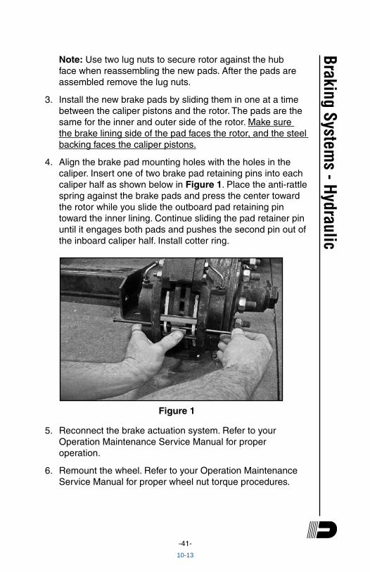
3. Install the new brake pads by sliding them in one at a time between the caliper pistons and the rotor. The pads are the same for the inner and outer side of the rotor. Make sure the brake lining side of the pad faces the rotor, and the steel backing faces the caliper pistons.
4. Align the brake pad mounting holes with the holes in the caliper. Insert one of two brake pad retaining pins into each caliper half as shown below in Figure 1. Place the anti-rattle spring against the brake pads and press the center toward the rotor while you slide the outboard pad retaining pin toward the inner lining. Continue sliding the pad retainer pin until it engages both pads and pushes the second pin out of the inboard caliper half. Install cotter ring.
Figure 1
5. Reconnect the brake actuation system. Refer to your Operation Maintenance Service Manual for proper operation.
6. Remount the wheel. Refer to your Operation Maintenance Service Manual for proper wheel nut torque procedures.
Braking Systems - Hydraulic
10-13
-42-
Instructions for Brake Caliper Kit 6K, 7K or 8K Hydraulic Disc BrakesNotice to BuyerIt is recommended that all brakes be replaced at the same time to ensure balanced braking performance.
Remove the old brake calipers1. Jack up trailer and secure on adequate capacity jack stands.
Follow trailer manufacturers recommendations for lifting and supporting the unit.
! CAUTIONDo not lift or support the trailer on any part of the axle or suspension system. Never go under any trailer unless it is properly supported on jack stands which have been rated for the load. Improperly supported vehicles can fall unexpectedly and cause serious injury or death.
2. Remove the wheel from the hub, leaving the brake exposed.
3. Disable the brake actuation system. Check that the hydraulic system has zero pressure and that the hub and rotor rotates freely.
4. For brakes produced after April 2008, the crossover brake line also attaches to the inboard side of the caliper mounting bracket using the metal tube clamp. Slide the clamp over the crossover brake line and bend it to the closed position. Apply anti-seize or similar thread lubricant to the ¹⁄₄-20, ¹⁄₂" bolt. Attach the tube clamp to the threaded hole in the caliper mounting bracket using the ¹⁄₄-20, ¹⁄₂" length bolt. Torque to 85-100 In. Lbs.
5. Remove the hose from the caliper, then remove the four caliper mounting bolts. Do not allow the caliper to hang from the hose.
Installing the new brake caliper1. First inspect the brake assembly for grooves, flaking,
cracks, heat checking, thickness variation, insufficient rotor Brak
ing
Syst
ems
- Hyd
raul
ic
10-13
-43-
thickness, and look to see that the mounting hardware is straight. Replace any component as needed (or desired) per manufacturer recommendations.
2. Assemble the new caliper assembly.
Note: Use two lug nuts to secure rotor against the hub face when reassembling the calipers. After the brake is assembled, remove the lug nuts.
3. One caliper will be used on the inboard side, with the hydraulic line fitting adapter installed on the top side of the piston boss. The other caliper will be used on the outboard side with the bleed screw installed at the top of the piston boss. Install both of these calipers onto the attaching bracket. Make sure that the bleed screw points up and is located on the outboard caliper. Torque bolts to 25-35 Ft. Lbs.
4. Connect the new crossover brake line on the bottom sides of the piston boss on both calipers.
Note: Make sure the crossover line fits snug around the calipers and rotor without touching the rotor. Spin the rotor to ensure there is proper clearance. Torque the crossover line to 12-15 Ft. Lbs. Torque the bleed screw and the hydraulic line fitting adapter to 60-76 Inch Lbs.
5. For brakes produced after April 2008, locate the crossover brake line threaded into the bottom side of both calipers. The crossover brake line is attached to the inboard side of the anchor yoke using a metal tube clamp. Remove the ¹⁄₄-20 bolt that connects the tube clamp to the yoke.
6. Reassemble the brake pads into the disc brake. Make sure to locate the brake lining side of the pads toward the rotor surface, and the steel side of the pads toward the calipers. Align the brake pad mounting holes with the holes in the caliper. Insert one of two brake pad retaining pins into each caliper half as shown previously in Figure 1. Place the anti-rattle spring against the brake pads and press the center toward the rotor while you slide the outboard pad retaining pin toward the inner lining. Continue sliding the pad retainer pin until it engages both pads and pushes the second pin out of the inboard caliper half. Install cotter ring.
Braking Systems - Hydraulic
10-13
-44-
7. Reconnect the brake actuation system. Refer to your Operation Maintenance Service Manual for proper operation.
8. Bleed and flush brake system per your actuation systems Operation Maintenance Service Manual.
9. Remount the wheel. Refer to your Operation Maintenance Service Manual for proper wheel nut torque procedures.
10. Spin wheel to ensure proper clearance between the wheel, crossover brake line, and the rotor.
Brak
ing
Syst
ems
- Hyd
raul
ic
10-13
-45-
Introduction to TroubleshootingProper brake function is critical to the safe operation of any vehicle. A properly installed vacuum/hydraulic, electric/hydraulic, or air/hydraulic system should not require any special attention with the exception of routine maintenance as defined by the manufacturer. If problems occur, the entire tow vehicle/trailer braking system should be analyzed by a qualified mechanic. Typical problems in a hydraulic braking system are:
• Air or vacuum leaks • Hydraulic system leaks • Air in brake lines • Water or other impurity in brake fluid • Rusted or corroded master or wheel cylinders • Actuation system malfunction
Please consult the following troubleshooting charts to determine the causes and solutions for common problems found in trailer braking systems.
CAUTIONThe maximum operating pressure for Dexter brakes:• 7" diameter drum brakes maximum operating pressure is 750 psi• 10" diameter and larger drum brakes maximum operating pressure is 1,000 psi• Hydraulic disc brakes (all sizes) maximum operating pressure is 1,600 psi
Braking Systems - Hydraulic
10-13
-46-
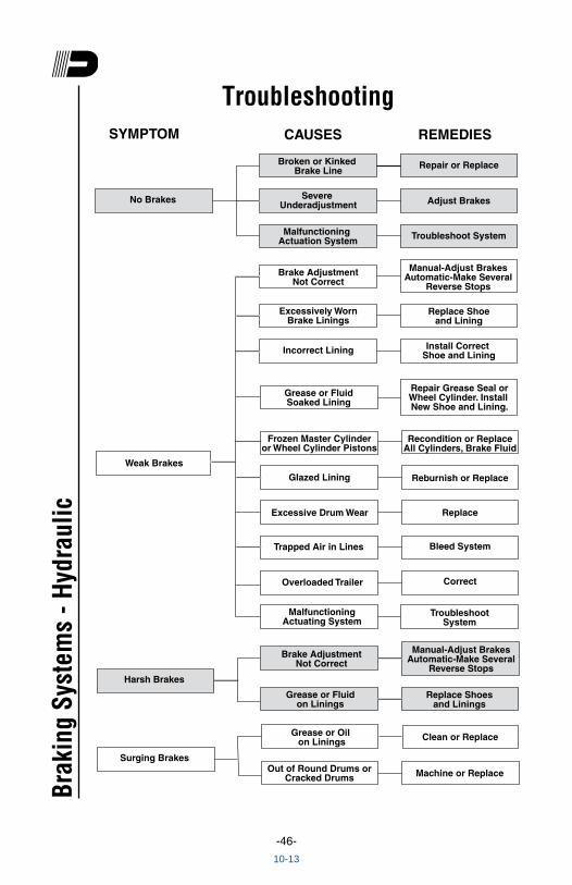
Troubleshooting
Broken or Kinked Brake Line
Malfunctioning Actuation System
Brake AdjustmentNot Correct
Excessively WornBrake Linings
Grease or FluidSoaked Lining
Glazed Lining
Excessive Drum Wear
Severe Underadjustment
Incorrect Lining
Trapped Air in Lines
Overloaded Trailer
Repair or Replace
Adjust Brakes
Troubleshoot System
Replace Shoeand Lining
Install Correct Shoe and Lining
Repair Grease Seal orWheel Cylinder. Install New Shoe and Lining.
Recondition or ReplaceAll Cylinders, Brake Fluid
Reburnish or Replace
Replace
Bleed System
Correct
No Brakes
Weak Brakes
Frozen Master Cylinderor Wheel Cylinder Pistons
Manual-Adjust BrakesAutomatic-Make Several
Reverse Stops
SYMPTOM CAUSES REMEDIES
MalfunctioningActuating System
TroubleshootSystem
Grease or Fluidon Linings
Replace Shoesand Linings
Manual-Adjust BrakesAutomatic-Make Several
Reverse StopsHarsh Brakes
Brake AdjustmentNot Correct
Machine or Replace
Surging Brakes
Grease or Oil on Linings
Out of Round Drums orCracked Drums
Clean or Replace
Brak
ing
Syst
ems
- Hyd
raul
ic
10-13
-47-
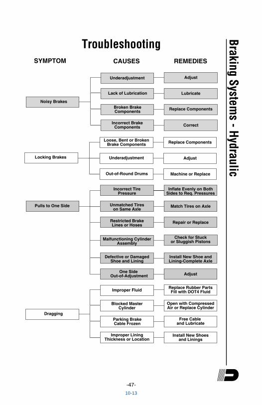
Troubleshooting
Hydtrbl.eps2/22/94
Loose, Bent or BrokenBrake Components
Underadjustment
Out-of-Round Drums
Replace Components
Adjust
Machine or Replace
Locking Brakes
Incorrect TirePressure
Restricted BrakeLines or Hoses
Malfunctioning CylinderAssembly
Defective or DamagedShoe and Lining
Blocked MasterCylinder
Parking BrakeCable Frozen
Unmatched Tireson Same Axle
One Side Out-of-Adjustment
Improper LiningThickness or Location
Inflate Evenly on BothSides to Req. Pressures
Match Tires on Axle
Repair or Replace
Install New Shoe andLining-Complete Axle
Adjust
Replace Rubber PartsFill with DOT4 Fluid
Open with CompressedAir or Replace Cylinder
Free Cable and Lubricate
Install New Shoesand Linings
Pulls to One Side
Improper Fluid
Dragging
Check for Stuckor Sluggish Pistons
SYMPTOM CAUSES REMEDIES
Lack of Lubrication
Broken BrakeComponents
Incorrect BrakeComponents
Adjust
Lubricate
Replace Components
Correct
Underadjustment
Noisy Brakes
Braking Systems - Hydraulic
10-13