Embed Size (px)
Citation preview
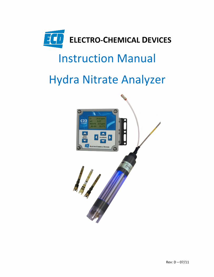
Rev: D – 07/11
ELECTRO-CHEMICAL DEVICES
Instruction Manual
Hydra Nitrate Analyzer

Page ii HYDRA NO3--N
PREFACE
Purchasing products from Electro-Chemical Devices, Inc. provides you with the finest liquid analytical
instrumentation available. If this is your first purchase from ECD, please read this manual before
installing and commissioning your new equipment.
If there are any questions concerning this equipment, please contact your local ECD representative, or
the factory directly at:
Electro-Chemical Devices, Inc.
1681 Kettering St.
Irvine, CA 92614 USA
Telephone: +1-949-336-6060
FAX: +1-949-336-6064
Website: www.ecdi.com
Email: [email protected]
© 2010 Electro-Chemical Devices, Inc. All rights reserved. No part of this manual may be used or reproduced in any form or by any means, or
stored in a database or retrieval system without prior written permission from Electro-Chemical Devices, Inc. Making copies of any part of this
manual for any purpose other than personal use is a violation of United States copyright laws. Document printed in the United States of
America.

HYDRA NO3--N Page iii
TABLE OF CONTENTS
PREFACE ........................................................................................................................................................ ii
TABLE OF CONTENTS .................................................................................................................................... iii
WARRANTY .................................................................................................................................................. vi
IMPORTANT SERVICE INFORMATION .......................................................................................................... vi
UNPACKING THE INSTRUMENT................................................................................................................... vii
1.0 GENERAL DESCRIPTION ........................................................................................................................... 1
1.0.0 Description ................................................................................................................................... 1
1.0.1 Chloride Ion Compensation ......................................................................................................... 1
1.0.2 Optional pH or Ammonium Measurement .................................................................................. 1
1.0.3 Temperature Compensation ........................................................................................................ 1
1.0.4 Cleaning and Maintenance .......................................................................................................... 1
1.1 FEATURES ............................................................................................................................................ 2
1.1.1 Features and Benefits .................................................................................................................. 2
1.2 Specifications ...................................................................................................................................... 2
1.2.1 Hydra Sensor ................................................................................................................................ 2
1.2.2 C22 Analyzer ................................................................................................................................ 3
1.3 Hydra Dimensional Drawing ............................................................................................................... 4
2.0 INSTALLATION ......................................................................................................................................... 5
2.1 UNPACKING ......................................................................................................................................... 5
2.2 ASSEMBLY ........................................................................................................................................... 5
2.2.1 Spray Cleaner ............................................................................................................................... 5
2.2.2 Immersion /Support Tube ............................................................................................................ 5
2.3 MOUNTING ......................................................................................................................................... 5
2.3.1 C-22 Analyzer ............................................................................................................................... 5
2.3.2 Hydra Sensor ................................................................................................................................ 6
2.4 WIRING ................................................................................................................................................ 6
2.4.1 Wiring, power .............................................................................................................................. 6
2.4.2 Wiring, Sensor .............................................................................................................................. 6
2.4.3 Wiring, 4-20 mA Outputs ............................................................................................................. 6
2.4.4 Wiring, Contact Relay Outputs ..................................................................................................... 7

Page iv HYDRA NO3--N
3.0 OPERATION ............................................................................................................................................. 8
3.1 KEYS ..................................................................................................................................................... 8
3.2 MENUS ................................................................................................................................................ 9
3.2.1 Nitrate Ion Channel 1 Menu Structure ........................................................................................ 9
3.2.2 Chloride Ion Channel 2 Menu Structure ...................................................................................... 9
3.2.3 pH or NH4+
Channel 3 Menu Structure ......................................................................................... 9
3.2.4 Graphical Display Screen ............................................................................................................ 10
3.2.5 Buffer Menu ............................................................................................................................... 10
3.2.6 Set-Up Menu .............................................................................................................................. 11
3.2.7 Status Menu ............................................................................................................................... 12
3.2.8 Configuration and Trim Menu.................................................................................................... 13
3.3 OUTPUTS ........................................................................................................................................... 13
3.3.1 Manual Mode (4-20 mA Hold Function) .................................................................................... 13
3.4.2 One AC10 with Two HYDRAs ...................................................................................................... 14
3.5 ION SELECTIVE FEATURES ................................................................................................................. 15
3.5.1 The Isopotential point ................................................................................................................ 15
3.5.2 Chloride Ion Interference Correction ......................................................................................... 16
4.0 START UP ............................................................................................................................................... 17
4.1 SET-UP AND CONFIGURATION .......................................................................................................... 17
4.1.1 Set Up Menus ............................................................................................................................. 17
4.1.2 Set Up Menu, MASTER/SLAVE ................................................................................................... 18
4.1.3 Configure and Trim Menu .......................................................................................................... 19
4.1.4 Configure and Trim Menu, MASTER/SLAVE ............................................................................... 20
4.2 CALIBRATION ..................................................................................................................................... 22
4.2.1 Recommended Materials ........................................................................................................... 22
4.2.2 Temperature Calibration ............................................................................................................ 23
4.2.3 Single point Calibration .............................................................................................................. 23
4.2.4 Two point Calibration ................................................................................................................. 24
4.2.5 Chloride Ion Compensation ....................................................................................................... 24
5.0 MAINTENANCE ...................................................................................................................................... 25
5.1 MAINTENANCE SCHEDULE ................................................................................................................ 25
5.2 CLEANING THE SENSOR ..................................................................................................................... 25

HYDRA NO3--N Page v
5.3 REPLACING THE ELECTRODES ........................................................................................................... 25
6.0 TROUBLESHOOTING .............................................................................................................................. 26
7.0 ENGINEERING DOCUMENTATION ......................................................................................................... 27
7.1 SPECIFICATIONS ................................................................................................................................ 27
7.2 OUTLINE & DIMENSIONAL DRAWING ............................................................................................... 28
7.2.1 Hydra Sensor Dimensions .......................................................................................................... 28
7.2.2 C-22 Dimensions ........................................................................................................................ 28
7.2.3 Sun Shield ................................................................................................................................... 29
7.3 WIRING DIAGRAM ............................................................................................................................. 30
7.3.1 Sensor Color Coded Diagram ..................................................................................................... 30
7.3.2 Instrument – Terminal Layout/Connections .............................................................................. 30
8.0 ORDERING INFORMATION .................................................................................................................... 31
8.1 PART NUMBERS/MODEL NUMBERS ................................................................................................. 31
8.2 ACCESSORIES ..................................................................................................................................... 31
8.3 SPARE PARTS ..................................................................................................................................... 32

Page vi HYDRA NO3--N
WARRANTY Electro-Chemical Devices, Inc. (ECD) warrants all products it manufactures to be free from defect in materials and factory
workmanship, and agrees to repair or replace any product that fails to perform, as specified, within one (1) year after date of
shipment. This warranty shall not apply to any product that has been:
1. Subjected to misuse, negligence or accident;
2. Connected, installed, adjusted or otherwise used not in accordance with the instructions furnished by ECD;
3. Repaired, modified or altered by persons not authorized by ECD, resulting in injury to the performance, stability or
reliability of the product.
This warranty is in lieu of any other warranty, expressed or implied. ECD reserves the right to make changes in the design or
construction of its products at any time, without prior notification, and without incurring any obligation to make any changes in
previously delivered products.
Seller’s sole liabilities and the buyer’s sole remedies under this agreement shall be limited to a refund in the purchase price, or
at ECD’s discretion, to the repair or replacement of any product that proves, upon ECD’s examination, to be defective, when
returned to the factory, transportation prepaid by the buyer, within one (1) year of the product’s original shipment date. Seller
shall not be liable for damages consequential or incidental to defects in any product, for failure of delivery in whole or in part,
for injuries resulting from its use, or for any other cause.
This warranty and the writing attached constitute the full understanding of seller and the buyer, and no terms, conditions,
understanding, or agreement purporting to modify or vary the terms hereof shall be binding unless hereafter made in writing
and signed by an authorized official of Electro-Chemical Devices, Inc.
This warranty does not cover pH, ORP or Specific Ion measurement, reference or combination electrodes or electrode
cartridges that have been commissioned in service.
IMPORTANT SERVICE INFORMATION Use only factory authorized components for repair. Tampering or unauthorized substitution of components may
adversely affect the operation of this product and may void the warranty.
If service or repair is required, please obtain the serial number(s) or sales order number of the product(s) in
question and contact ECD’s Service Department at:
+1-800-729-1333 (USA/Canada) or +1-949-336-6060
or email [email protected]
A Return Material Authorization (RMA) number must be obtained from the service department before returning
any material to ECD. All material returned to ECD shall be shipped prepaid to the factory.

HYDRA NO3--N Page vii
UNPACKING THE INSTRUMENT
Your Electro-Chemical Devices instrument has been carefully packaged to protect it from damage during
shipment and dry storage. Upon receipt please follow the procedure outlined below.
1. Before unpacking, inspect the condition of the shipping container to verify proper handling by
the carrier. If damage is noted, save the shipping container as proof of mishandling for the
carrier.
2. Check the contents of the shipping container with the items and quantities shown on the
packing list. Immediately report any discrepancies to ECD.
3. Save the original packing material until you are satisfied with the contents. In the event the
product(s) must be returned to ECD, the packing material will allow you to properly ship it to
ECD.
4. Familiarize yourself with the instrument before installation, and follow proper installation and
wiring procedures.

HYDRA NO3--N Page 1
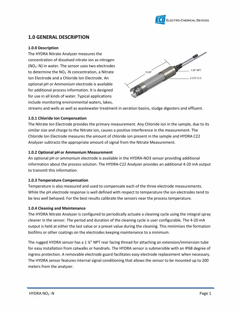
1.0 GENERAL DESCRIPTION
1.0.0 Description
The HYDRA Nitrate Analyzer measures the
concentration of dissolved nitrate ion as nitrogen
(NO3--N) in water. The sensor uses two electrodes
to determine the NO3--N concentration, a Nitrate
Ion Electrode and a Chloride Ion Electrode. An
optional pH or Ammonium electrode is available
for additional process information. It is designed
for use in all kinds of water. Typical applications
include monitoring environmental waters, lakes,
streams and wells as well as wastewater treatment in aeration basins, sludge digesters and effluent.
1.0.1 Chloride Ion Compensation
The Nitrate Ion Electrode provides the primary measurement. Any Chloride ion in the sample, due to its
similar size and charge to the Nitrate ion, causes a positive interference in the measurement. The
Chloride Ion Electrode measures the amount of chloride ion present in the sample and HYDRA C22
Analyzer subtracts the appropriate amount of signal from the Nitrate Measurement.
1.0.2 Optional pH or Ammonium Measurement
An optional pH or ammonium electrode is available in the HYDRA-NO3 sensor providing additional
information about the process solution. The HYDRA-C22 Analyzer provides an additional 4-20 mA output
to transmit this information.
1.0.3 Temperature Compensation
Temperature is also measured and used to compensate each of the three electrode measurements.
While the pH electrode response is well defined with respect to temperature the ion electrodes tend to
be less well behaved. For the best results calibrate the sensors near the process temperature.
1.0.4 Cleaning and Maintenance
The HYDRA Nitrate Analyzer is configured to periodically actuate a cleaning cycle using the integral spray
cleaner in the sensor. The period and duration of the cleaning cycle is user configurable. The 4-20 mA
output is held at either the last value or a preset value during the cleaning. This minimizes the formation
biofilms or other coatings on the electrodes keeping maintenance to a minimum.
The rugged HYDRA sensor has a 1 ¼” NPT rear facing thread for attaching an extension/immersion tube
for easy installation from catwalks or handrails. The HYDRA sensor is submersible with an IP68 degree of
ingress protection. A removable electrode guard facilitates easy electrode replacement when necessary.
The HYDRA sensor features internal signal conditioning that allows the sensor to be mounted up to 200
meters from the analyzer.

Page 2 HYDRA NO3--N
1.1 FEATURES
1.1.1 Features and Benefits
• Separate, economical, easily replaceable Nitrate, Chloride and optional pH electrodes
• Fast and Accurate Nitrate Measurement NO3- or NO3
--N
• Automatic compensation for Cl- interference
• Temperature compensated NO3--N measurement
• Rugged PVC design with removable electrode guard for easy maintenance
• Integral Spray Head Cleaner
� Cleans sensor in situ with turbulence caused by pressurized air
• Internal Signal Conditioning allows up to 200 meters between Sensor and Analyzer
1.2 Specifications
1.2.1 Hydra Sensor
• Three Electrode System with spray cleaner
• Nitrate ISE (NO3--N) is the primary measurement
• Chloride ISE is used for compensation of the NO3- signal.
• Optional pH or NH4+ electrode
• The Sensor is waterproof with an ingress rating of IP 68.
Measurement Range
• NO3--N: 0.1 to 1000 ppm
• Cl-: 0.1 to 10,000 ppm
• pH: 2-12 pH
• NH4+: 0.1 to 1000 ppm
Operating Temperature
• 0° C to 40° C (32° F to 104° F)
Min/Max Flow Rate by the sensor
• Minimum 0.1 m/s
• Maximum 3.0 m/s
Wetted Materials
• PVC, PES, PVDF, PTFE, Viton, Glass, 316 SS
Accuracy
• ± 3% of reading, dependent on Calibration
Response Time
• T90 approximately 1 minute

HYDRA NO3--N Page 3
Electrode Life
• ISEs: 4- 6 months, typical
• pH electrode: 6-12 months, typical
1.2.2 C22 Analyzer
Measurements
• Nitrate: 0.1 ppb to 1000 ppm as NO3-- N
• Chloride: 0.1 ppm to 1000 ppm
• pH: 0 to 14 pH or NH4+: 0.1 to 1000 ppm
• Temperature: 0° C to 100° C (32° F to 212° F)
Compensation
• Chloride: 0.1 to 1000 ppm
• Temperature: 0° - 50°C
Display
• 2.5” X 1.75” backlit LCD
• 4 lines of Text
• Graphical display, NO3-- N vs. Time
Enclosure
• NEMA 4X, LxWxD: 5.7” x 5.7” x 7”
Outputs
• (2) 4-20 mA maximum load 800 ohms @ 24 VDC
• mA #1: 0.1 to 50 mg/l NO3-- N (User Configurable)
• mA #2 (Optional): 2 - 12 pH or 0.1 to 50 mg/l NH4+ (User Configurable)
• Optionally up to (4) 4-20 mA outputs*

Page 4 HYDRA NO3--N
Input Power
• 110/220 VAC @ 50/60 Hz
Alarm Relay Ratings
• SPDT 230 VAC/5A or 30 VDC/5A resistive max. All are configured as Normally Open (NO).
Relay Standard Configuration Master Configuration Slave Configuration
1 Spray Cleaner NH4-N Alarm NH4-N Alarm
2 NH4-N Alarm (PV 1) Digital Input to Slave pH Alarm
3 Spray Cleaner
4 Diverter Valve
1.3 Hydra Dimensional Drawing
Figure 1.3
1.3.1 Parts List:
o HYDRA Sensor with Electrodes, Calibration Cap,
o 30’ of ¼” air tubing, Electrode Removal Tool

HYDRA NO3--N Page 5
2.0 INSTALLATION
2.1 UNPACKING
Carefully remove the HYDRA sensor from its shipping container. Inspect the sensor for damage. Verify
the electrodes, Nitrate, Chloride, (optional pH or NH4+) and the Spray Cleaner Nozzle are installed in the
sensor housing. The electrodes should be hand tightened into place so that the sealing o-rings are not
visible. The electrodes are supplied with protective caps that must be removed before start up. Do not
remove the caps until ready to use.
### NEVER SUPPORT THE HYDRA SENSOR BY THE CABLE, IRREPAIRABLE DAMAGE WILL OCCUR ###
2.2 ASSEMBLY
The HYDRA Sensor is shipped completely assembled, before use it must be connected to the analyzer
and an air supply. Connect the spray cleaner feed tube to a compressed air supply controlled by a
solenoid valve (not supplied). Attach an immersion/support tube (not supplied). Finally connect the
sensor wires and 110 VAC power to the analyzer as shown on the wiring diagram. Connect the Cleaner
Relay to the solenoid and connect the 4-20 mA Output(s) and Alarm Relay to the Control System, (PLC or
DCS). The HYDRA is now ready to use.
2.2.1 Spray Cleaner
The Spray Cleaner uses compressed air to create turbulence around the electrodes which removes dirt
and films from the measurement surfaces. Depending on the process being measured the cleaner
should be actuated for 15-30 seconds every 0.25 -2 hour period. The spray cleaner connection is a ¼”
compression fitting and requires between 25-75 psi air pressure. The air supply is controlled with a user
supplied solenoid valve through Relay 1 in the C-22 analyzer. The solenoid valve should be a 110 AC
powered, <10 watt device. Wire the solenoid to Relay 1 as described in Section 2.4.4 below.
### NEVER SUPPORT THE HYDRA SENSOR BY THE CABLE, IRREPAIRABLE DAMAGE WILL OCCUR ###
2.2.2 Immersion /Support Tube
Feed the cable and compressed air line through the immersion/support tube (not supplied). Connect a
support tube to the 1 ¼” MNPT thread at the rear of the sensor. The Hydra sensor weighs approximately
5.3 lbs. The support tube must be able to support the weight of the HYDRA sensor in the user’s
installation, whether vertical or angled. The recommended material for the immersion tube is 1.5”
Schedule 80 PVC pipe with a reducer fitting to 1 ¼” FNPT.
2.3 MOUNTING
2.3.1 C-22 Analyzer
Mount the C-22 in a location where there is easy access to the analyzer and sensors. Install the system
in an area where vibrations, electromagnetic and radio frequency interference are minimized or absent.
Do not mount in direct sunlight or areas of extreme heat (temperature > 120°F). The NEMA 4X C-22 is
suitable for outdoor use but it is best to mount it with a protective cover or sunshield, PN 1000260-1
with vertical pole mounting hardware or 1000260-2 for horizontal rail mounting hardware.
Page 6 HYDRA NO3--N
There are three basic installation methods for the C-22, Wall Mount (UM), Panel Mount (PM) and Pipe
Mount (HM). The Pipe Mounting hardware includes 2” “U” bolts for attaching to standard 2” handrails.
(See the installation drawings in Section 9.3 at the rear of the manual)
2.3.2 Hydra Sensor
Install the sensor where the measured sample is representative of the entire process. Although the
sensor will function in a quiescent sample, flow improves the measurement. The recommended
minimum flow is 0.1 m/sec.
Securely mount the HYDRA sensor with the measuring end at least 6”away from the tank wall and
bottom. Ensure that the sensor is immersed at least 6” at all times.
Use care when servicing the sensor to ensure that the sensor does not hit the tank wall or bottom which
could break the sensing electrodes.
2.4 WIRING
Electrical wiring should only be conducted by qualified personnel. See the wiring color code for the
Hydra Sensor and the C-22 wiring diagram in Section 7.3 below.
2.4.1 Wiring, power
Attach power cable as shown in the diagram in Section 7.3 or the inside of the C22 cover. Feed the cable
through the gland fitting on the right hand side of the C-22. Tighten the cable gland to provide a good
seal to the cable. The instrument can be powered up at this point with no harm to the analyzer but it is
best to wait until the sensors are installed.
2.4.2 Wiring, Sensor
Attach the sensor wires as described on the diagram inside the C22 cover. Feed the sensor cable
through the gland fitting on the left hand side of the C-22. Do not use the same gland fitting for the AC
power or Alarm/Relays. The green terminal strip connectors are detachable from the circuit boards.
Remove the connector by pulling straight back from the circuit board.
2.4.3 Wiring, 4-20 mA Outputs
The 4-20 mA output is an unpowered output, 24V must be supplied from an external source, the PLC or
DCS receiving the signal or from the internal PS2 power supply.
If the internal PS2 Power Supply is used, first connect a jumper wire between Terminal #1 (RTN) on the
PS2 Power Supply Board and Terminal #2 of the 4-20 mA 1 output connector, the two slot connector on
the top of the Channel 2 input card. (See diagram in Section 7.3) Then connect a shielded 22 gauge
twisted pair communication cable to Terminal #2 (+24V) on the PS2 power supply board and Terminal
#1 of the 4-20 mA 1 connector.
If a second mA output is supplied connect it in the same manner, jumper Terminal #1 of the PS2 board
to Terminal #2 of the 4-20 mA 2 output terminal strip then connect the two wire communication cable
to PS2 Terminal #2 and mA 2 Terminal #1.

HYDRA NO3--N Page 7
If the 4-20 mA loop is powered from an external source then simply connect a shielded 22 gauge twisted
pair communication wire to Terminals #1 and #2 of the 4-20 mA terminal on the Channel 2 input card.
The standard Hydra C-22 is configured with the NO3--N on mA 1 and pH on mA 2.
2.4.4 Wiring, Contact Relay Outputs
The standard configuration has two SPDT 230V 5 A relays that can be wired either normally open (NO)
or normally closed (NC). The default configuration is set to use the relays as normally open. Relay 1
actuates the solenoid for the air blast spray cleaner and Relay 2 is an NO3--N alarm relay, either a High or
Low Alarm.
Relay 1
Connect the Line terminal of the 110VAC power to the C (common) terminal of Relay 1. Connect the
Cleaner solenoid wires to the neutral terminal of the 110 VAC power and the NO (normally open)
terminal of Relay 1. (See Section 7.3)
Relay 2
Wire Relay 2 as a NO relay. Relay 2 is an alarm relay and should be connected to the Control System or
an external alarm.
Do not run the cable through the same cable gland fitting as the electrodes or the 4-20 mA signals.
The MASTER configuration has (4) SPDT 230V 5 A relays that are wired as normally open (NO) relays.
Relay 1
Wire Relay 1 as a NO relay. Relay 1 is an alarm relay and should be connected to the Control System or
an external alarm.
Do not run the cable through the same cable gland fitting as the electrodes or the 4-20 mA signals.
Relays 2 (NO) to Slave Analyzer, Aux In Terminals
Relay 3 (NO) to AC10 Air Blast Spray Cleaner, Compressor terminals
Relay 4 (NO) to AC10 Air Blast Spray Cleaner, Diverter terminals
The SLAVE configuration has (2) SPDT 230V 5 A relays that are wired as normally open (NO) relays.
Relays 1, 2
Wire Relays 1 and 2 as a NO relays. Relays 1 and 2 are alarm relays and should be connected to the
Control System or an external alarm.
Do not run the cable through the same cable gland fitting as the electrodes or the 4-20 mA signals.

Page 8 HYDRA NO3--N
3.0 OPERATION
This section will provide a basic overview of the C22 Analyzer/Controller. It covers the basic Menu
structure, the function of the MENU SELECT keys and the CALIBRATE keys.
The C-22 HYDRA analyzer has three measurement channels:
Channel 1, Nitrate as Nitrogen, NO3--N,
Channel 2, Chloride, Cl- and
Channel 3, (optional) pH or NH4+
3.1 KEYS
The blinking cursor indicates the active point where menus can be selected or numerical values
adjusted. There are two sets of keys on the C22 analyzer, the MENU SELECT keys and the CALIBRATE
keys.
The MENU SELECT keys are used to move the cursor vertically changing the displayed menu. These keys
are also used to Save/Accept the calibration data and exit the calibration menu.
The CALIBRATE keys are used to enter menus, change numerical values and move the cursor
horizontally.
To enter a calibration menu or parameter adjustment line simultaneously press both of the
Horizontal CALIBRATE keys, ◄CALIBRATE►
Pressing either of the Horizontal CALIBRATE keys separately will move the cursor horizontally to the
point under the digit to be adjusted. The Vertical CALIBRATE keys are used to adjust numeric values.
Pressing the upper key will increase the value and pressing the lower key will decrease the value. When
HYDRA NO3--N Page 9
the cursor is on a menu line, not in the menu, pressing the down CALIBRATE key will return the cursor to
the HOME Screen from any menu.
3.2 MENUS
There are three sets of menus on the Model C-22. The Channel 1 menus (PV1) the Nitrate Ion channel
(NO3--N), the Channel 2 menus (PV2) the Chloride Ion channel and the Channel 3 menus (PV3) the pH or
NH4+ channel. Pressing the MENU SELECT UP key will first access the Chloride channel and then the pH
channel, pressing the MENU SELECT DOWN key will access the Nitrate channel. Follow the guide below
for the general menu structure.
3.2.1 Nitrate Ion Channel 1 Menu Structure
Screen Displayed Button Pressed
Home Screen MENU SELECT ▼
Graphical display MENU SELECT ▼
Parameter Selection Screen (Ch 1 Buffer) MENU SELECT ▼
Parameter Selection Screen (Ch 1 Set-Up) MENU SELECT ▼
Parameter Selection Screen (Ch 1 Status) MENU SELECT ▼
Configure/ Trim Menu MENU SELECT ▲..... To return to the Home screen
3.2.2 Chloride Ion Channel 2 Menu Structure
Screen Displayed Button Pressed
Home Screen MENU SELECT ▲
pH Manual Mode Screen MENU SELECT ▲
Parameter Selection Screen (Ch 2 Status) MENU SELECT ▲
Parameter Selection Screen (Ch 2 Set-Up) MENU SELECT ▲
Parameter Selection Screen (Ch 2 Buffer) MENU SELECT ▲
To channel 3 MENU SELECT ▼….. To return to the Home screen
3.2.3 pH or NH4+
Channel 3 Menu Structure
Screen Displayed Button Pressed
Parameter Selection Screen (Ch 2 Buffer) MENU SELECT ▲
Parameter Selection Screen (Ch 3 Status) MENU SELECT ▲
Parameter Selection Screen (Ch 3 Set-Up) MENU SELECT ▲
Parameter Selection Screen (Ch 3 Buffer) MENU SELECT ▲
Contrast (adjustment screen) MENU SELECT ▼….. To return to the Home screen
Page 10 HYDRA NO3--N
3.2.4 Graphical Display Screen
This Graphical Display is only available in the Channel 1 menu. It is located one screen down from the
Home Screen. It displays a user assigned output value, for example, 4-20 mA1 vs. time. The Graphical
Display variables of; which Output is displayed and what Time interval is used is configured in the
Channel 1 Set-Up Menu. See Section 3.2.6, below, for more information on the Set-Up Menu.
3.2.5 Buffer Menu
The Buffer Menus are Calibration Menus. To access the Buffer Menu the cursor must be flashing in front
of the “Ch X Buffer” line. Simultaneously press both of the Horizontal CALIBRATE keys to enter the
Calibration screens. The calibration is structured for a two point calibration.
The first calibration “1 NO3-N” is the “zero point” calibration. This sets a base millivolt value to a specific
ion concentration. The concentration is adjustable to suit the measurement range, see procedure
below. When adjusting a value first move the cursor to the largest integer to be adjusted, perform the
adjustment and then move to the next lower value. When a calibration is performed the Cal line will
display the millivolt value associated with calibration standard solution. The Cal value can be reset to 0
millivolts by “entering” the Cal line.
The second calibration screen is the “slope, mV/ppm” calibration. This calibration should use a standard
solution that is at least 10X the concentration of the solution used in the first calibration. Scroll down to
the “2 NO3-N” line and enter the value of the standard solution and the Cal line will display the new
slope, mV/ppm. Follow the same procedure for calibration of Channels 2 & 3.
Screen Displayed Button Pressed
Ch1 Buffer
◄ CALIBRATE ► (enter the calibration menu by pressing
both ◄► simultaneously)
1 NO3-N 4.00 ppm
Cal .0 mV
◄ CALIBRATE ►(enter line, zero pt. Cal 1)
Sensor should be in the Cal 1 solution. (example 5 ppm)
1 NO3-N 4.00 ppm
Cal 393.5 mV
To set Calibration Sol. Value use the CALIBRATE ◄ or ► to
move cursor. Use the ▲or▼ to adjust the integer value.
1 NO3-N 5.00 ppm
Cal 393.5 mV
Wait for reading to stabilize….
MENU SELECT ▼ (accept Calibration)
1 NO3-N 5.00 ppm
Cal 393.5 mV
MENU SELECT ▼ (move to Cal line)
1 NO3-N 5.00 ppm
Cal 393.5 mV
MENU SELECT ▼(move to Cal 2, Slope)
Remove sensor, rinse and place in Cal 2 solution
2 NO3-N 00.0 ppm
Cal 29.6 mV/dec
◄ CALIBRATE ► (enter screen)
2 NO3-N 00.0 ppm
Cal 29.6 mV/dec
To set Calibration Sol. Value use the CALIBRATE ◄ or ► to
move cursor. Use the ▲or▼ to adjust the integer value.
2 NO3-N 50.0 ppm
Cal 29.6 mV/dec
Wait for reading to stabilize….
MENU SELECT ▼ (accept Calibration)
2 NO3-N 50.0 ppm
Cal 29.2 mV/dec
CALIBRATE ▼ (return to Home Screen)
HYDRA NO3--N Page 11
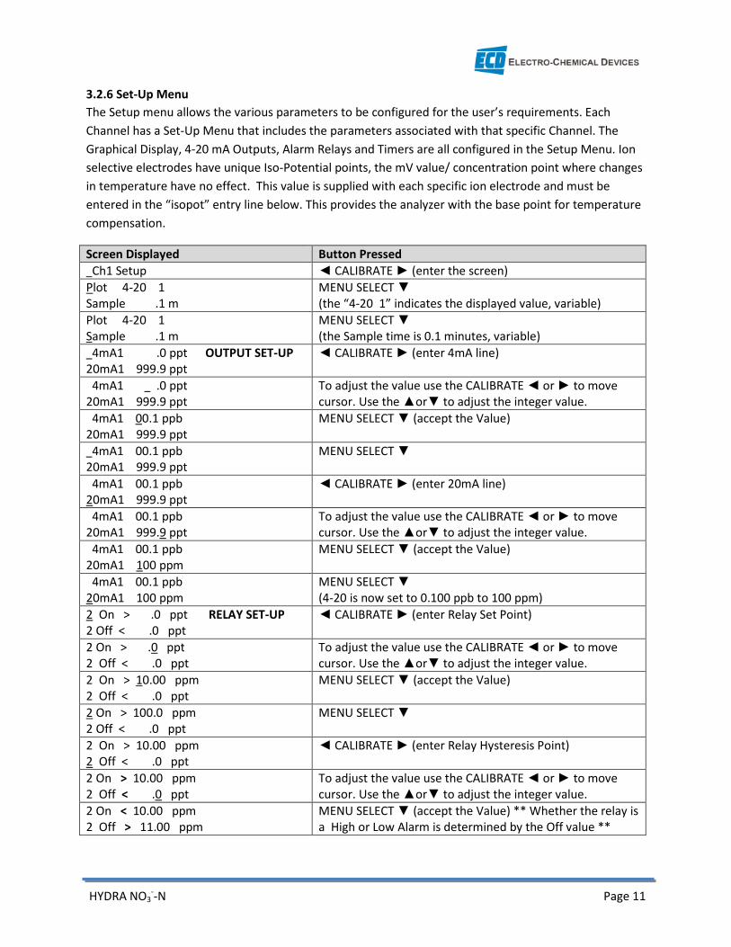
3.2.6 Set-Up Menu
The Setup menu allows the various parameters to be configured for the user’s requirements. Each
Channel has a Set-Up Menu that includes the parameters associated with that specific Channel. The
Graphical Display, 4-20 mA Outputs, Alarm Relays and Timers are all configured in the Setup Menu. Ion
selective electrodes have unique Iso-Potential points, the mV value/ concentration point where changes
in temperature have no effect. This value is supplied with each specific ion electrode and must be
entered in the “isopot” entry line below. This provides the analyzer with the base point for temperature
compensation.
Screen Displayed Button Pressed
Ch1 Setup ◄ CALIBRATE ► (enter the screen)
Plot 4-20 1
Sample .1 m
MENU SELECT ▼
(the “4-20 1” indicates the displayed value, variable)
Plot 4-20 1
Sample .1 m
MENU SELECT ▼
(the Sample time is 0.1 minutes, variable)
4mA1 .0 ppt OUTPUT SET-UP
20mA1 999.9 ppt
◄ CALIBRATE ► (enter 4mA line)
4mA1 .0 ppt
20mA1 999.9 ppt
To adjust the value use the CALIBRATE ◄ or ► to move
cursor. Use the ▲or▼ to adjust the integer value.
4mA1 00.1 ppb
20mA1 999.9 ppt
MENU SELECT ▼ (accept the Value)
4mA1 00.1 ppb
20mA1 999.9 ppt
MENU SELECT ▼
4mA1 00.1 ppb
20mA1 999.9 ppt
◄ CALIBRATE ► (enter 20mA line)
4mA1 00.1 ppb
20mA1 999.9 ppt
To adjust the value use the CALIBRATE ◄ or ► to move
cursor. Use the ▲or▼ to adjust the integer value.
4mA1 00.1 ppb
20mA1 100 ppm
MENU SELECT ▼ (accept the Value)
4mA1 00.1 ppb
20mA1 100 ppm
MENU SELECT ▼
(4-20 is now set to 0.100 ppb to 100 ppm)
2 On > .0 ppt RELAY SET-UP
2 Off < .0 ppt
◄ CALIBRATE ► (enter Relay Set Point)
2 On > .0 ppt
2 Off < .0 ppt
To adjust the value use the CALIBRATE ◄ or ► to move
cursor. Use the ▲or▼ to adjust the integer value.
2 On > 10.00 ppm
2 Off < .0 ppt
MENU SELECT ▼ (accept the Value)
2 On > 100.0 ppm
2 Off < .0 ppt
MENU SELECT ▼
2 On > 10.00 ppm
2 Off < .0 ppt
◄ CALIBRATE ► (enter Relay Hysteresis Point)
2 On > 10.00 ppm
2 Off < .0 ppt
To adjust the value use the CALIBRATE ◄ or ► to move
cursor. Use the ▲or▼ to adjust the integer value.
2 On < 10.00 ppm
2 Off > 11.00 ppm
MENU SELECT ▼ (accept the Value) ** Whether the relay is
a High or Low Alarm is determined by the Off value **

Page 12 HYDRA NO3--N
2 On < 10.00 ppm (Low Alarm
2 Off > 11.00 ppm example)
2 On > 10.00 ppm (High Alarm
2 Off < 9.500 ppm example)
MENU SELECT ▼(If the NO3--N drops below 10.0 ppm the
contact closes until it is higher than 11 ppm. If the Off value
is set to 9.5 ppm then the contact will switch to a High
Alarm, closing at 10.0 ppm and re-opening below 9.5 ppm.)
Timer 1: periodic
←Clock
◄ CALIBRATE ►
Per 0d00 :00 :00 Cleaning Timer
Now 0 00 :00 :00 (Per sets the time
On 0 00 :00 :00 between cleaning
Off 0 00 :00 :00 cycles)
◄ CALIBRATE ►
(Set the Period to 1 hour then every hour the Now Clock
will reset to 0:00:00 and trigger the On Timer which is set at
0:00:00, starting the cleaning cycle.)
Per 0d00 :00 :00
Now 0 00 :00 :00
On 0 00 :00 :00
Off 0 00 :00 :00
To adjust the value use the CALIBRATE ◄ or ► to move
cursor. Use the ▲or▼ to adjust the integer value, 30 min
then MENU SELECT ▼ (accept the Value)
MENU SELECT ▼, MENU SELECT ▼, MENU SELECT ▼
Per 0d00 :30 :00
Now 0 00 :00 :00 (Set the Off time
On 0 00 :00 :00 at 30 seconds)
Off 0 00 :00 :30
◄ CALIBRATE ► (enter the Off line, the duration of the
cleaning cycle) To adjust the value use the CALIBRATE ◄ or
► to move cursor. Use the ▲or▼ to adjust the integer
value, then MENU SELECT ▼ (accept the Value)
Timer 2: oneshot↑
←timer 1←clock
◄ CALIBRATE ►
4-20 mA hold time after cleaning cycle, (CT + 1 minute)
Now 0 00 :00 :00 Manual Mode Timer
On 0 00 :00 :00 (Hold Function)
Off 0 00 :01 :30 (Set at 1 min 30 sec)
MENU SELECT ▼, MENU SELECT ▼, ◄ CALIBRATE ►
To adjust the value use the CALIBRATE ◄ or ► to move
cursor. Use the ▲or▼ to adjust the integer value.
Cl coef .004
Cl comp Off
MENU SELECT ▼ NO3 electrode selectivity ratio for Cl-
(NO3 ppm) – 0.004(Cl- ppm) = NO3 –N concentration
Cl coef .004
Cl comp Off
MENU SELECT ▼ Cl- compensation should be Off for
Calibration and On for Measurement
TC .333 %/°C
Isopot 20.0 mV
MENU SELECT ▼ Temperature Compensation (no adjustments needed)
TC .333 %/°C
Isopot .0 mV ** Mandatory **
◄ CALIBRATE ► (Enter Iso-Potential Entry line)
**Iso-Potential value supplied with each electrode**
TC .333 %/°C
Isopot 20.0 mV
To adjust the value use the CALIBRATE ◄ or ► to move
cursor. Use the ▲or▼ to adjust the integer value.
TC .333 %/°C
Isopot 187.0 mV
MENU SELECT ▼ (accept the Value)
MENU SELECT ▼
Noise Filter 5 CALIBRATE ▼ (return to Home Screen)
3.2.7 Status Menu
The Status menu displays the actual uncompensated millivolt value from the sensor, very handy
information for troubleshooting. The day and time, hours: minutes: seconds, are also displayed.
Screen Displayed Button Pressed
Ch1 Status ◄ CALIBRATE ► (enter screen)
Fri 09:11:28 MENU SELECT ▼
Input 364.2 mV CALIBRATE ▼ (return to Home Screen)

HYDRA NO3--N Page 13
3.2.8 Configuration and Trim Menu
The Configure/Trim menu provides access to the menus used to assign parameters, define functions and
trim input and output signals. This group of menus should rarely be needed as the instrument was
configured at the factory before testing and shipment. The basic structure is as follows. See the “System
22 Configuration Manual” for details about these menus, available at www.ecdi.com.
Screen Displayed Button Pressed
Configure/Trim ◄ CALIBRATE ► (enter screen)
Passwords MENU SELECT ▼(allows menus to be password protected)
Default Display MENU SELECT ▼(defines Home Screen)
4-20 assign MENU SELECT ▼(Assigns parameter/function to mA output)
Manual Mode MENU SELECT ▼(Allows manual control of mA outputs)
Relay assign/Test MENU SELECT ▼(Assigns triggering parameter to a relay)
PID Assign MENU SELECT ▼(Assigns PID to a PV)
PWM Assign MENU SELECT ▼(Assigns Pulse Width Modulation to a PV)
Clock and timers MENU SELECT ▼(Sets Clock function, assigns Timers)
Logic Gates MENU SELECT ▼(assigns AND/OR gates)
Ion Species MENU SELECT ▼(Sets Ion Measured)
General MENU SELECT ▼( Not Used)
°C/°F & Temp Cal MENU SELECT ▼( allows temperature trim/cal, choose °C/°F)
4-20 Trim/Test MENU SELECT ▼(allows mA trim)
Millivolt Trim CALIBRATE ▼ (return to Home Screen)
3.3 OUTPUTS
The Standard C-22 HYDRA Analyzer has two 4-20 mA outputs. The default configuration has “mA 1”
configured for NO3-N, 4-20 mA = .100 ppb to 50 ppm and “mA 2” is configured for pH, 4-20 mA = 2-12
pH. To reconfigure the outputs see Section 3.2.6, Set-Up Menu, above.
The Outputs, mA 1 and mA 2, are held at the “Last Value” by Timer 2 during the Air Blast Cleaning Cycle.
The Outputs return to live readings one minute after the cleaning cycle ends. Timer 2 is a “one-shot”
timer triggered by Timer 1. When Timer 1 triggers, it starts Timer 2 which is set to run for a period of
time equal to the cleaning time plus one minute.
3.3.1 Manual Mode (4-20 mA Hold Function)
The % Output is displayed on the Home Screen for the NO3-N output, mA 1, and one screen above the
Home Screen for the pH % Output, mA 2.
The outputs can be set for manual control by simultaneously pressing both horizontal CALIBRATE keys
when the cursor is in front of the % Output line. An “M” will be displayed in front of the % Output value.
Page 14 HYDRA NO3--N
The Output will remain frozen at the last value until the Manual Mode is turned off. The Manual Mode
hold function is commonly used to freeze the outputs during maintenance and calibration cycles. While
in Manual Mode the Output can be adjusted between 0 and 99.9% using the CALIBRATE keys, very
useful for troubleshooting loop communication problems.
To exit Manual Mode press the left CALIBRATE arrow, ◄, three times and the “M” will disappear, the
Output will return to a live reading.
3.4 CONTACTS-Alarm Relays
3.4.1 Standard Configuration
Relay 1 is configured to control the Air Blast Spray Cleaner. It is triggered by Timer 1. Timer 1 is
configured as a periodic timer. The default setting for the period is 15 minutes with the duration set at
30 seconds. The period and duration of the cleaning cycle is user configurable and dependent on the
application. For water going to the clarifier an adequate cleaning cycle may be, every two hours for 15
seconds, where incoming water to an aeration basin may require a 30 second cleaning cycle every 15
minutes.
The Now clock is an arbitrary timer. The Period determines the amount of time that must pass before
the Now clock resets to 00 hours, 00 minutes and 00 seconds, 00: 00: 00. The On time is the start time
and it is set at 00: 00: 00, so every time the clock resets Relay 1 is triggered. The Off time sets the
duration of Timer 1 and is set at 00: 00: 30, thirty seconds. (See Section 3.2.6 above)
To Change how often the Spray Cleaner actuates, change the Per line to the desired period. The display
is set for days, hours: minutes: seconds, 0d00: 00: 00.
To Change the duration of the Cleaning cycle change the Off line. If the duration is changed from the
default value of 30 seconds then the Manual Mode Timer should be adjusted to allow the sensor to
stabilize after the cleaning cycle. Adjust Timer 2; Off line; to the new Clean Time (CT) + 1 minute.
Relay 2 is configured as a high alarm triggering at 10.0 ppm NH4+-N. The value can be changed in the Set-
Up Menu as shown in Section 3.2.6. Changing the > sign to a < sign in the On line changes the set point
from a high to a low alarm. This can also be accomplished by setting the Off value higher than the On
value which forces an automatic sign change. The Off value is the hysteresis point that the PV has to
correct to before the relay disengages.
3.4.2 One AC10 with Two HYDRAs
When two HYDRA Analyzers are connected to one AC10 Air Blast Spray Cleaning System then one C22
Analyzer becomes the MASTER and the other C22 Analyzer is a SLAVE.
3.4.2.1 Master Configuration
Relay 1 is configured as a high alarm triggering at 10.0 ppm NO3-N. The value can be changed in the Set-
Up Menu as shown in Section 3.2.6. Changing the > sign to a < sign in the On line changes the set point
from a high to a low alarm. This can also be accomplished by setting the Off value higher than the On

HYDRA NO3--N Page 15
value which forces an automatic sign change. The Off value is the hysteresis point that the PV has to
correct to before the relay disengages.
Relay 2 is configured to trigger the Digital Input (Aux In) of the SLAVE analyzer. This initiates the Manual
Mode function of the SLAVE analyzer, placing the mA outputs in a Last Value Hold (Bumpless).
Relay 3 is configured to control the Air Blast Spray Cleaner. It is triggered by Timer 1. Timer 1 is
configured as a periodic timer. The default setting (Set Up Menu) for the period is 15 minutes with the
duration set at 30 seconds. This triggers a cleaning cycle every 15 minutes alternating between the
MASTER and the SLAVE units, so each HYDRA sensor is cleaned every 30 minutes. (see Relay 4
below)The period and duration of the cleaning cycle is user configurable and dependent on the
application. For water going to the clarifier an adequate cleaning cycle may be, every two hours for 15
seconds, where incoming water to an aeration basin may require a 30 second cleaning cycle every 15
minutes.
The Now clock is an arbitrary timer. The Period determines the amount of time that must pass before
the Now clock resets to 00 hours, 00 minutes and 00 seconds, 00: 00: 00. The On time is the start time
and it is set at 00: 00: 00, so every time the clock resets Relay 1 is triggered. The Off time sets the
duration of Timer 1 and is set at 00: 00: 30, thirty seconds. (See Section 3.2.6 above)
To Change how often the Spray Cleaner actuates, change the Per line to ½ the desired period. The
display is set for days, hours: minutes: seconds, 0d00: 00: 00.
To Change the duration of the Cleaning cycle change the Off line. If the duration is changed from the
default value of 30 seconds then the Manual Mode Timer should be adjusted to allow the sensor to
stabilize after the cleaning cycle. Adjust Timer 2; Off line; to the new Clean Time (CT) + 1 minute.
Relay 4 is configured to control the diverter valve which alternates the Air Blast between the two
sensors. It is triggered by Timer 2. Timer 2 is configured as a periodic timer. The default setting (Set Up
Menu) for the period is 30 minutes with the duration set at 30 seconds. The Period of Timer 2 must be
twice the Period of Timer 1 and have the same duration.
3.5 ION SELECTIVE FEATURES
The Hydra C22 analyzer has several features unique to Ion Selective Electrode measurements,
Isopotential and Interfering Ion Correction. The measurement range of the sensors is from some ppb
level to some ppm level, XXX ppb – XXX ppm, not the traditional 0 – XXX common to most
measurements, there is no zero value. This is most evident when configuring the 4-20 mA outputs.
3.5.1 The Isopotential point
Isopot in the menu is the mV value of the specific sensor where changes in the temperature of the
solution do not change the output of the sensor. This is the base point for temperature compensation
correction. Most pH electrodes have an isopotential near pH 7, but each type of Ion Selective electrode
has a unique isopotential value. Each NO3- and Cl- electrode is supplied with an Isopot that must be
entered in the respective Set-Up Menu.
Page 16 HYDRA NO3--N
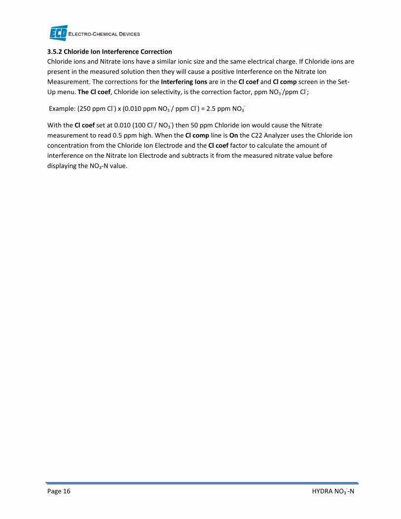
3.5.2 Chloride Ion Interference Correction
Chloride ions and Nitrate ions have a similar ionic size and the same electrical charge. If Chloride ions are
present in the measured solution then they will cause a positive Interference on the Nitrate Ion
Measurement. The corrections for the Interfering Ions are in the Cl coef and Cl comp screen in the Set-
Up menu. The Cl coef, Chloride ion selectivity, is the correction factor, ppm NO3-/ppm Cl
-;
Example: (250 ppm Cl-) x (0.010 ppm NO3
-/ ppm Cl
-) = 2.5 ppm NO3
-
With the Cl coef set at 0.010 (100 Cl-/ NO3
-) then 50 ppm Chloride ion would cause the Nitrate
measurement to read 0.5 ppm high. When the Cl comp line is On the C22 Analyzer uses the Chloride ion
concentration from the Chloride Ion Electrode and the Cl coef factor to calculate the amount of
interference on the Nitrate Ion Electrode and subtracts it from the measured nitrate value before
displaying the NO3-N value.

HYDRA NO3--N Page 17
4.0 START UP
The HYDRA Analyzer and Sensor was assembled and tested at the factory before shipment. The sensor
was then disconnected from the analyzer, cleaned and packaged for shipment. The HYDRA C22 analyzer
is configured as shown below and should be ready to use aside from any changes the user may wish to
make to the Outputs, Cleaning Timers and Alarm Set points.
Complete all of the steps in Section 2 INSTALLATION (above) before proceeding further. These steps
include:
1. Install the Analyzer in a suitable environment.
2. Determine an installation method and representative sample point for the sensor.
3. Connect the Air Blast Spray Cleaner tube to a solenoid controlled air supply, 1-4 bar (15-60 psig).
4. Wire the Power, Outputs, Contact Relays and the HYDRA Sensor to the HYDRA C22 Analyzer.
Familiarize yourself with the MENU Structure of the HYDRA C22 Analyzer, Section 3 (above).
4.1 SET-UP AND CONFIGURATION
The HYDRA C22 analyzer is configured as shown below. Changes to the default configuration can be
easily made as described in Section 3 above.
4.1.1 Set Up Menus
Ch 1 Setup Menu Settings Settings
Plot 4-20 1
Sample .1 m
4mA1 0.100 ppb
20mA1 50.00 ppm
2 On > 10.00 ppm
2 Off < 9.500 ppm
Timer 1 : periodic
Per 0d00 :30 :00
Now 0 00 :00 :00
On 0 00 :00 :00
Off 0 00 :00 :15
Timer 2 : oneshot↑ Now 0 00 :00 :00
On 0 00 :00 :00
Off 0 00 :01 :15
Cl coef 0.004
Cl comp On
TC .333 %/°C
Isopot XXX.X mV
Nitrate Ion value
Noise filter 5
Ch 2 Setup Menu Settings Settings
TC .333 %/°C
Isopot XXX.X mV
Chloride Ion value
Noise filter 5
Page 18 HYDRA NO3--N
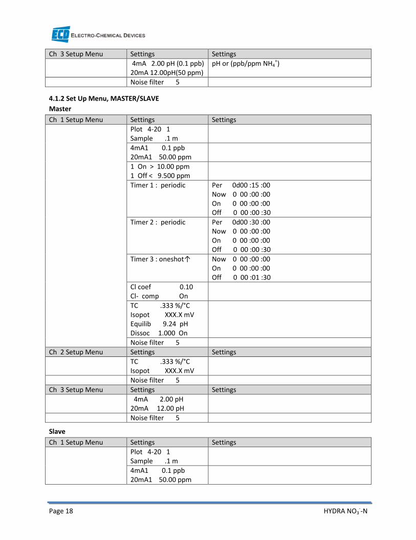
Ch 3 Setup Menu Settings Settings
4mA 2.00 pH (0.1 ppb)
20mA 12.00pH(50 ppm)
pH or (ppb/ppm NH4+)
Noise filter 5
4.1.2 Set Up Menu, MASTER/SLAVE
Master
Ch 1 Setup Menu Settings Settings
Plot 4-20 1
Sample .1 m
4mA1 0.1 ppb
20mA1 50.00 ppm
1 On > 10.00 ppm
1 Off < 9.500 ppm
Timer 1 : periodic
Per 0d00 :15 :00
Now 0 00 :00 :00
On 0 00 :00 :00
Off 0 00 :00 :30
Timer 2 : periodic Per 0d00 :30 :00
Now 0 00 :00 :00
On 0 00 :00 :00
Off 0 00 :00 :30
Timer 3 : oneshot↑ Now 0 00 :00 :00
On 0 00 :00 :00
Off 0 00 :01 :30
Cl coef 0.10
Cl- comp On
TC .333 %/°C
Isopot XXX.X mV
Equilib 9.24 pH
Dissoc 1.000 On
Noise filter 5
Ch 2 Setup Menu Settings Settings
TC .333 %/°C
Isopot XXX.X mV
Noise filter 5
Ch 3 Setup Menu Settings Settings
4mA 2.00 pH
20mA 12.00 pH
Noise filter 5
Slave
Ch 1 Setup Menu Settings Settings
Plot 4-20 1
Sample .1 m
4mA1 0.1 ppb
20mA1 50.00 ppm

HYDRA NO3--N Page 19
Ch 1 Setup Menu,
cont’d
1 On > 10.00 ppm
1 Off < 9.500 ppm
Timer 1 : oneshot↑ Now 0 00 :00 :00
On 0 00 :00 :00
Off 0 00 :01 :30
Cl coef 0.10
Cl- comp On
TC .333 %/°C
Isopot XXX.X mV
Equilib 9.24 pH
Dissoc 1.000 On
Noise filter 5
Ch 2 Setup Menu Settings Settings
TC .333 %/°C
Isopot XXX.X mV
Noise filter 5
Ch 3 Setup Menu Settings Settings
4mA 2.00 pH
20mA 12.00 pH
1 On > 7.50 pH
1 Off < 7.40 pH
Noise filter 5
4.1.3 Configure and Trim Menu
The Configure and Trim is configured as shown be and does not require any adjustments.
Menu Settings
Passwords No Pass Words (not configured)
Default display 0 (not configured)
4-20 assign 4-20 1 : Ch1 PV
4-20 2 : Ch3 PV
Manual Mode Ch1 man mode on: 4-20 1
Initial ch1 manual setting: Bumpless
Ch1 auto entry: timer 2
Ch2 man mode on: nothing
Initial ch2 manual setting: Bumpless
Ch2 auto entry: unused
Ch3 man mode on: 4-20 2
Initial ch3 manual setting: Bumpless
Ch3 auto entry: timer 2
Relay assign/test Relay 1 timer 1
Relay 2 Ch1 PV
(Relays 3-8 set to missing)
PID Assign PID A unused
PID B unused
Page 20 HYDRA NO3--N
Clock and timers Clock: Software
Hide Clock N
Hide Rate Y
Hide Flash N
Man trig OK Y
Timer 1: periodic
Timer2: oneshot↑
Retriggerable N
Resettable N
Trig 2 timer 1
(Timers 3-8 unused)
Logic gates All unused
Ion Species Ch1 ion NO3-N
Ch2 ion Cl-
General No Menu
°C/°F & temp cal 1 Trim °C .0
Unit 200.0 °C
4-20 Trim/Test (not configured)
Millivolt trim (not configured)
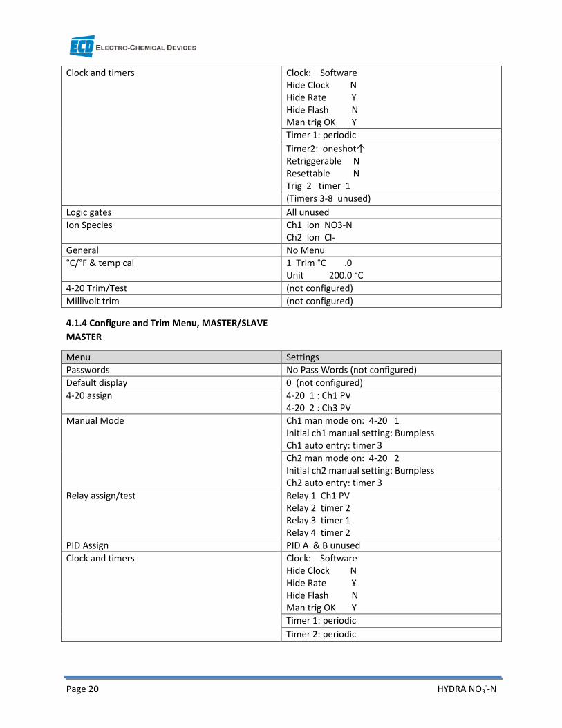
4.1.4 Configure and Trim Menu, MASTER/SLAVE
MASTER
Menu Settings
Passwords No Pass Words (not configured)
Default display 0 (not configured)
4-20 assign 4-20 1 : Ch1 PV
4-20 2 : Ch3 PV
Manual Mode Ch1 man mode on: 4-20 1
Initial ch1 manual setting: Bumpless
Ch1 auto entry: timer 3
Ch2 man mode on: 4-20 2
Initial ch2 manual setting: Bumpless
Ch2 auto entry: timer 3
Relay assign/test Relay 1 Ch1 PV
Relay 2 timer 2
Relay 3 timer 1
Relay 4 timer 2
PID Assign PID A & B unused
Clock and timers Clock: Software
Hide Clock N
Hide Rate Y
Hide Flash N
Man trig OK Y
Timer 1: periodic
Timer 2: periodic
HYDRA NO3--N Page 21
Timer3: oneshot↑
Retriggerable N
Resettable N
Trig 2 AND A
Logic gates AND Gate A
In Timer 1
In Timer/2
OR Gates A, B, C Not Used
AND Gate B, C Not Used
Ion Species Ch1 ion NO3-N
Ch2 ion Cl-
General No Menu
°C/°F & temp cal 1 Trim °C .0
Unit 200.0 °C
4-20 Trim/Test (not configured)
Millivolt trim (not configured)
SLAVE
Menu Settings
Passwords No Pass Words (not configured)
Default display 0 (not configured)
4-20 assign 4-20 1 : Ch1 PV
4-20 2 : Ch3 PV
Manual Mode Ch1 man mode on: 4-20 1
Initial ch1 manual setting: Bumpless
Ch1 auto entry: timer 1
Ch2 man mode on: 4-20 2
Initial ch3 manual setting: Bumpless
Ch2 auto entry: timer 1
Relay assign/test Relay 1 Ch 1 PV
Relay 2 Ch 2 PV
(Relays 3-8 set to missing)
PID Assign PID A unused
PID B unused
Clock and timers Clock: Software
Hide Clock N
Hide Rate Y
Hide Flash N
Man trig OK Y
Timer 1: oneshot↑
Retriggerable N
Resettable N
Trig 2 Ext /1
(Timers 3-8 unused)
Logic gates All unused
Ion Species Ch1 ion NO3-N
Ch2 ion Cl-
Page 22 HYDRA NO3--N
General No Menu
°C/°F & temp cal 1 Trim °C .0
Unit 200.0 °C
4-20 Trim/Test (not configured)
Millivolt trim (not configured)
4.2 CALIBRATION
The HYDRA Nitrate Analyzer was calibrated at the factory using the Two Point Calibration described
below. The sensor was assembled and placed beaker of equilibration solution for 8-12 hours before
starting the calibration. The Chloride Ion and Nitrate Ion electrodes sensing membranes require several
hours to properly hydrate/ equilibrate to the measured solution. The calibration sets the zero potential
and slope for each of the sensors into the analyzers memory.
Since the factory calibration characterizes the complete measurement system the initial user calibration
should only require a standardization of the Nitrate Ion Electrode once the HYDRA has equilibrated to
the process solution.
The Factory Calibration and all subsequent calibrations should be performed in the following sequence:
1. Temperature Calibration
2. Chloride Electrode calibration in 1 ppm (or 10 ppm) and 100 ppm solutions (2 point)
3. Nitrate Electrode calibration in 1 ppm (or 10 ppm) and 100 ppm solutions (2 point)
Calibration checks should be performed weekly by comparison to a grab sample or immersing the
HYDRA sensor into a standard solution with known pH, Cl- and NO3
--N values. Performing a Single Point
Calibration will eliminate any offset found in the calibration check. Continuous drifting of the Chloride or
Nitrate ion reading may indicate the electrode needs to be replaced. (See Section 6 Trouble Shooting
below)
Two Point Calibration is required whenever an electrode is replaced, pH, Chloride or Nitrate. Two Point
Calibrations are also recommended every two months to verify the response of the electrodes is greater
than 50 mV/decade.
4.2.1 Recommended Materials
pIon Calibration Solutions
1. 1 ppm Cl-, 500 ml (Part# 2010453)
2. 100 ppm Cl-, 500 ml (part# 2010454)
3. 1 ppm NO3--N, 500 ml (Part# 2010451)
4. 100 ppm NO3--N, 500 ml (part# 2010452)
pH Calibration Solutions (optional)
1. pH 4.01, 500 ml (Part # 2010100) or 1.00 ppm NH4-N (Part # 2010445)
2. pH 7.00, 500 ml (Part # 2010101) or 100 ppm NH4-N (Part # 2010446)
Accessories

HYDRA NO3--N Page 23
1. 1 liter plastic beakers
2. Distilled Water for rinsing
3. Calibrated thermometer with 0.1 °C graduations
4. Stir plate with magnetic stir bars.
4.2.2 Temperature Calibration
Place the HYDRA sensor in a beaker of water so that the bottom 3 inches (7.6 cm) of the body is
immersed. Allow the sensor to equilibrate for 10 minutes. Verify the displayed temperature agrees with
the thermometer. If not, then adjust the temperature in the Configure/Trim > °C/°F & temp cal > 1 Trim
°C menu to agree with the thermometer. This calibration was performed in the factory calibration but it
is advisable to perform a temperature check every 2-3 months.
4.2.3 Single point Calibration
Single Point Calibrations are used to standardize the sensor’s reading to a known value typically to
eliminate errors caused by drift or large changes in the makeup of the measured solution. A Single Point
Calibration adjusts the base potential of the sensor by shifting the response curve to a higher or lower
level but it does not affect the slope (mV/ppm) of the curve.
Single point calibration is available for each of the measured parameters in the appropriate Buffer
Menu, Channel 1 Buffer for the NO3--N, Channel 2 Buffer for the Cl
- and Channel 3 Buffer for pH or NH4
+.
(See the Single Point Calibration Screen table below)
Immerse the front end of the sensor into a container of the calibration solution, enter the value of the
calibration solution or the value derived from a grab sample into the “1 (ion) xxx ppm” line of the
Buffer menu as described in Section 3.2.5 above. Accept the reading when stable by pressing either of
the MENU SELECT keys. The lower line in the menu, the Cal line will show the new mV value associated
with the entry.
***Important Note for Nitrate Calibrations*** When using the 1 ppm and 100 ppm NO3--N calibration
solutions to calibrate the HYDRA C22 analyzer the chloride ion compensation, the “Cl comp” line in the
Channel 1 Setup menu should be turned on, it is on by default.
If the Single Point Calibration is the first point in a Two Point Calibration it is customary to use the
solution with the lowest value for the single point calibration. There are no restrictions on the value
entered in the “1 (ion) xxx ppm” line of the Buffer menu; it can be higher or lower than the value in line
2 of the menu. For the pH calibration the zero point is set with pH 7.0 calibration buffer and the slope is
set with the pH 4.01 calibration buffer.
Single Point Calibration Screens
Channel Screen Recommended Solution
Ch1 Buffer (NO3-N) 1NO3-N 1.000 ppm
Cal 460.0 mV
1.0 ppm NO3-N (Part# 2010451)
or Grab Sample value
Ch2 Buffer (Cl-) 1Cl- 1.000 ppm
Cal 165 mV
1.0 ppm Cl (Part# 2010453)
or Grab Sample value

Page 24 HYDRA NO3--N
Ch3 Buffer (pH) 1 pH 7.00 pH
Cal 3.1 mV
pH 7.0 Buffer (part# 2010101)
or Grab Sample value
Ch3 Buffer (NH4-N) 1NH4-N 1.000 ppm
Cal 320.0 mV
1.0 ppm NH4-N (Part# 2010445)
or Grab Sample value
4.2.4 Two point Calibration
The second point of a Two Point Calibration sets the slope of the sensor, the mV per decade. The slope is
calculated by comparing the millivolt values and ppm values in the “1NO3-N 1.00 ppm” line to the
values in the “2NO3-N 100 ppm” line of the Buffer Menu. The concentration of the solution used for
the second point should be at least 10 times higher than the value used in the first point of the
calibration. The recommended calibration standards for both the nitrate ion and chloride ion
calibrations are 1 ppm and 100 ppm. Perform a two point calibration whenever an electrode is replaced.
After completing the single point calibration, see section 4.2.3 above, rinse the sensor with distilled
water and gently dab it dry with a paper towel or soft tissue. Carefully rinsing the sensor prevents errors
in the calibration due to carryover from the first solution. Place the sensor in the second solution, either
the pH 4.01 buffer or one of the 100 ppm solutions and wait for the reading to stabilize before accepting
the value. See section 3.2.5 above for further instruction.
4.2.5 Chloride Ion Compensation
Chloride ions have a positive interference on the Nitrate Ion Electrode, the nitrate reading is higher than
the actual value. The Chloride Ion Compensation, Cl comp, adjusts the measured nitrate ion
concentration using the measured chloride concentration and the interference/selectivity value, the Cl
coef, and subtracts the resulting amount from the Nitrate Ion Signal. The Cl coef value in the NO3-N Set
Up screen allows the interference ratio to be adjusted as needed. The default setting is Cl coef = .004
which is 250 chloride ions produce the same signal as 1 nitrate ion, Ks = 0.04 would change the
correction to 25:1. The 0.004 correction factor is good for most solutions with levels of chloride greater
than 50 ppm.
Each Chloride Ion Electrode should have similar characteristics but adjustments are necessary when the
chloride electrode is replaced or when low levels of chloride are present in the solution. If the nitrate ion
concentration is less than expected when compared to a grab sample measurement then adjust the Cl
coef value to a smaller value. Adjusting from 0.004 > 0.002 for example would increase the chloride to
nitrate ion ratio from 250:1 to 500:1 thereby slightly increasing the displayed nitrate ion concentration
by subtracting less in the compensation. See section 3.2.6 above.

HYDRA NO3--N Page 25
5.0 MAINTENANCE
5.1 MAINTENANCE SCHEDULE
The HYDRA sensor requires little maintenance since most of the required cleaning is accomplished by
the Air Blast Spray Cleaner. Determining the proper cleaning cycle and duration for the application will
keep the front end of the sensor clean for extended periods but weekly inspection of the sensing end is
recommended.
Weekly calibration checks versus a grab sample are recommended to minimize any drift in the sensor.
Once the stability of the sensor has been established in the process, the time between calibration
checks can be adjusted. A calibration check must occur at least once per month.
The HYDRA should be checked monthly in calibration solutions for proper span of both the Nitrate and
Chloride electrodes. The electrodes start life with a span in the 55 mV/decade range and drop off into
the 40 mV/decade range as they age. Readings below 40 mV/decade indicate the electrode should be
replaced. Depending on the characteristics of the water being measured the Ion Selective electrodes
should last 3-6 months.
5.2 CLEANING THE SENSOR
The HYDRA sensor can be rinsed with water and wiped with a soft brush or cloth to remove most
coatings. DO NOT clean the Chloride or Nitrate ion electrodes with a stiff brush or vigorous wiping as the
sensing membrane is easily scratched or torn. DO NOT use alcohols or organic solvents to clean the
sensor, the Nitrate electrode will be irreparably harmed. The sensor can be soaked in a weak detergent
solution to remove oily coatings or dilute HCl, 2-3%, for 15 minutes to help remove stubborn coatings.
The pH, Chloride ISE and HYDRA housing can be cleaned in a more rigorous manner since the plastic
body, Chloride ISE and glass membrane are more durable than the Nitrate Ion Selective Electrode.
5.3 REPLACING THE ELECTRODES
The three electrodes, Nitrate, Chloride and pH are easily replaceable by simply removing the electrode
guard, screwing out the old sensor and screwing in the new one using the supplied installation tool.
Make sure no water gets inside the sensor when removing the electrodes. Water will cause the internal
electronics to fail. If the electronics are compromised the complete HYDRA sensor must be replaced.
The nitrate electrode, the chloride electrode and pH electrodes are combination electrodes. The
reference electrodes are combined to a single signal which is used for all the measurements.
Apply a thin film of o-ring lubricant to the o-rings on the electrode before installing it into the sensor
housing. Use the supplied electrode installation tool to remove or install electrodes into the sensor. The
use of pliers or other tools is not recommended as they may crack the electrode housing.
Page 26 HYDRA NO3--N
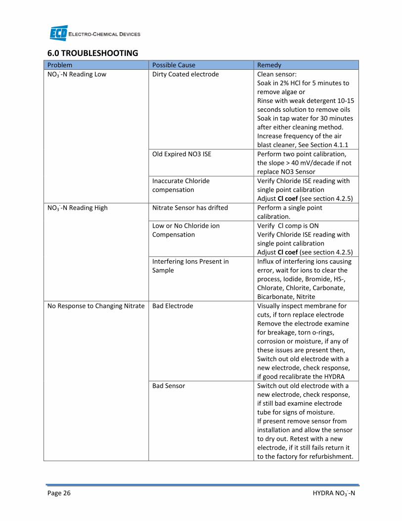
6.0 TROUBLESHOOTING
Problem Possible Cause Remedy
NO3--N Reading Low Dirty Coated electrode Clean sensor:
Soak in 2% HCl for 5 minutes to
remove algae or
Rinse with weak detergent 10-15
seconds solution to remove oils
Soak in tap water for 30 minutes
after either cleaning method.
Increase frequency of the air
blast cleaner, See Section 4.1.1
Old Expired NO3 ISE Perform two point calibration,
the slope > 40 mV/decade if not
replace NO3 Sensor
Inaccurate Chloride
compensation
Verify Chloride ISE reading with
single point calibration
Adjust Cl coef (see section 4.2.5)
NO3--N Reading High Nitrate Sensor has drifted Perform a single point
calibration.
Low or No Chloride ion
Compensation
Verify Cl comp is ON
Verify Chloride ISE reading with
single point calibration
Adjust Cl coef (see section 4.2.5)
Interfering Ions Present in
Sample
Influx of interfering ions causing
error, wait for ions to clear the
process, Iodide, Bromide, HS-,
Chlorate, Chlorite, Carbonate,
Bicarbonate, Nitrite
No Response to Changing Nitrate Bad Electrode Visually inspect membrane for
cuts, if torn replace electrode
Remove the electrode examine
for breakage, torn o-rings,
corrosion or moisture, if any of
these issues are present then,
Switch out old electrode with a
new electrode, check response,
if good recalibrate the HYDRA
Bad Sensor Switch out old electrode with a
new electrode, check response,
if still bad examine electrode
tube for signs of moisture.
If present remove sensor from
installation and allow the sensor
to dry out. Retest with a new
electrode, if it still fails return it
to the factory for refurbishment.
HYDRA NO3--N Page 27
7.0 ENGINEERING DOCUMENTATION
7.1 SPECIFICATIONS
Sensor
A Three Electrode system with spray cleaner, Nitrate ISE (NO3-- N) is the primary measurement. The
Chloride ISE is used to compensate the NO3- signal. An optional pH electrode is available for pH
measurement. The Sensor is waterproof with an ingress rating of IP 68.
Measurement Range
NO3-- N: 0.1 to 1000 ppm
Operating Temperature
0° C to 40° C (32° F to 104° F)
Min/Max Flow Rate
Minimum 0.1 m/s
Maximum 3.0 m/s
Wetted Materials
PVC, PES, PVDF, PTFE, Viton, Glass, 316 SS
Accuracy
± 3% of reading, dependent on Calibration
Response Time
T90 1 minute
Electrode Life
ISEs: 4- 6 months, typical
pH electrode: 6-12 months, typical
C22 Analyzer
Measurements
Nitrate: 0.01 to 1000 ppm as NO3-- N
Chloride: 0.01 to 1000 ppm
pH: 0 to 14 pH or NH4+: 0.1 to 1000 ppm
Temperature: 0° C to 100° C (32° F to 212° F)
Compensation
Chloride: 0.1 to 1000 ppm
Display
2.5” X 1.75” backlit LCD, 4 lines of Text & Graphical
Enclosure
NEMA 4X, LxWxD: 5.7” x 5.7” x 7
Outputs
(2) 4-20 mA maximum load 800 ohms @ 24 VDC
Configured: 0.1 to 20 mg/l NO3-- N; and 0 – 14 pH or 0.1 to 20 mg/l NH4
+
Optionally up to (4) 4-20 mA outputs

Page 28 HYDRA NO3--N
Input Power
110/220 VAC @ 50/60 Hz
Alarm Relay Ratings
(2) SPDT 230 VAC/5A or 30 VDC/5A resis0ve max.
Relay (1) Spray Cleaner, Relay (2) Alarm
Optionally up to (8) Relays
7.2 OUTLINE & DIMENSIONAL DRAWING
7.2.1 Hydra Sensor Dimensions
7.2.2 C-22 Dimensions
Panel Mount Dimensions and Cut-out Pattern

HYDRA NO3--N Page 29
Wall Mounting Dimensions, Screw Hole Pattern
7.2.3 Sun Shield

Page 30 HYDRA NO3--N
7.3 WIRING DIAGRAM
7.3.1 Sensor Color Coded Diagram
The White wire is either the pH signal or Ammonium signal on the option 3 electrode designs.
7.3.2 Instrument – Terminal Layout/Connections

HYDRA NO3--N Page 31
8.0 ORDERING INFORMATION
The HYDRA Nitrate Analyzer is a complete measurement system including the C22 analyzer/controller
(p/n 16LA2221.LA00) and the multiple parameters HYDRA Sensor (p/n 1290030-3). The Nitrate Ion
measurement is fully compensated for the effects of changes in the Chloride ion concentration in the
measured solution. The sensor features an Air Blast Cleaner that minimizes maintenance in the dirtiest
applications.
8.1 PART NUMBERS/MODEL NUMBERS
Part No. Model and Product Description
1290030-3 HYDRA NO3-N Sensor,
Complete, NO3, Cl-, pH, Temp, Spray Cleaner head and 30 ft. cable
1290030-4 HYDRA NO3-N Sensor, (No pH Sensor)
Complete, NO3, Cl-, Temp, Spray Cleaner head and 30 ft. cable
1290030-5 HYDRA NO3-N Sensor,
Complete, NO3-, Cl
-, NH4
+, Temp, Spray Cleaner head and 30 ft. cable
16LA2221.L100 HYDRA C22 NO3-N Analyzer, Standard
Cl- compensated & pH, (2) 4-20 mA output, 0.1 – 50 ppm NO3-N and (2) relays
16LA2221.L1L0 HYDRA C22 NO3-N Analyzer, SLAVE
Cl- compensated & pH, (2) 4-20 mA output, 0.1 – 50 ppm NO3-N and (2) relays
16LA2421.L1K0 HYDRA C22 NO3-N Analyzer, MASTER
Cl- compensated & pH, (2) 4-20 mA output, 0.1 – 50 ppm NO3-N and (4) relays
16L02221.L000 HYDRA C22 NO3-N Analyzer, Standard
Cl- compensated, no pH, (2) 4-20 mA output, 0.1 – 50 ppm NO3-N and (2) relays
16L02221.L0L0 HYDRA C22 NO3-N Analyzer, SLAVE
Cl- compensated, no pH, (2) 4-20 mA output, 0.1 – 50 ppm NO3-N and (2) relays
16L02421.L0K0 HYDRA C22 NO3-N Analyzer, MASTER
Cl- compensated, no pH, (2) 4-20 mA output, 0.1 – 50 ppm NO3-N and (4) relays
16LB2221.LT00 HYDRA C22 NO3-N Analyzer, Standard, Cl- compensated, NH4+, (2) 4-20 mA
outputs, 0.1 - 20 ppm NO3--N, 0.1 - 20 ppm NH4+ and (2) relays
16LB2221.LTL0 HYDRA C22 NO3-N Analyzer, SLAVE, Cl- compensated, NH4+, (2) 4-20 mA outputs,
0.1 - 20 ppm NO3--N, 0.1 - 20 ppm NH4+ and (2) relays
16LB2421.LTK0 HYDRA C22 NO3-N Analyzer, MASTER, Cl- compensated, NH4+, (2) 4-20 mA
outputs, 0.1 - 20 ppm NO3--N, 0.1 - 20 ppm NH4+ and (4) relays
8.2 ACCESSORIES
Part No. Accessories Description
1000254-XX Immersion Assembly, 1 ½” Slip x 45°, 1 ¼” NPT sensor connection and 1 ½” Slip x Cable feed through Elbow End Cap, XX= Length in ft.
1000254-99 Immersion Assembly, 1 ½” Slip by 45° 1 ¼” NPT sensor connection and 1 ½” Slip x Cable feed through Elbow End Cap, Fittings Only , User supplied Pipe (1 ½” Pipe)
2000255-1 2” Handrail Swivel Mounting Bracket
2010451 Nitrate Calibration solution, NO3-N, 1 ppm (500 ml)
2010452 Nitrate Calibration solution, NO3-N, 100 ppm (500 ml)
2010453 Chloride Calibration solution, 1 ppm (500 ml)
2010454 Chloride Calibration solution, 100 ppm (500 ml)

Page 32 HYDRA NO3--N
2010100 pH 4 Buffer Calibration solution (500 ml)
2010101 pH 7 Buffer Calibration solution (500 ml)
2010445 Ammonium Calibration solution, NH4-N 1 ppm
2010446 Ammonium Calibration solution, NH4-N 100 ppm
1000260-1 Sun Shield with Pole Mounting Hardware (Vertical Pole)
1000260-2 Sun Shield with Rail Mounting Hardware (Horizontal Rail)
1000300-1 4-20 mA USB Data Logger
8.3 SPARE PARTS
Part No. Spare Parts Description
2005086.VIT Nitrate Electrode Cartridge (recommended spare)
2005008.VIT Chloride Electrode Cartridge (recommended spare)
2005145.VIT pH Electrode Cartridge (recommended spare)
2005084.VIT Ammonium Electrode Cartridge (recommended spare)
3300854-1 Replacement Spray Nozzle
3501078-1 PVC Front Sensor Guard
3500007 Electrode Replacement Tool


![[XLS] · Web viewF14/3437 F14/3433 F14/3432 F14/3431 F14/3430 F14/3422 F14/3417 F14/3411 F14/3398 F14/3397 F14/3396 F14/3394 F14/3393 F14/3392 F14/3391 F14/3388 F14/3387 F14/3386](https://img.pdfslide.us/doc/110x75/5af067057f8b9ad0618e00da/xls-viewf143437-f143433-f143432-f143431-f143430-f143422-f143417-f143411.jpg)


![BYU TMA201 historiography [f14]](https://img.pdfslide.us/doc/110x75/55a0f5071a28abd44f8b46f4/byu-tma201-historiography-f14.jpg)