Embed Size (px)
Citation preview
middot S-1 middotmiddotmiddot shy
NRELTP-440-21272
UC Category 1213
DE96007901
Hybrid2The Hybrid SystemSimulation Model Version 10
User Manual
E lan Baring-Gould
bullbullbullbull --bull
National Renewable Energy Laboratory
1617 Cole Boulevard
Golden Colorado 8040 1-3393 A Division of Midwest Research Institute Operated for the US Department of Energy
under Contract No DE-AC02-83CH 10093
Prepared under task noWE617330
June 1996
Cover Page Photo Credits Ed Linton New World Power Technology Company Waitsfield Vermont Warren Gretz National Renewable Energy Laboratory Golden Colorado
Cover Page Design Deb Braun National Renewable Energy Laboratory Golden Colorado
NOTICE
This report was prepared as an account of work sponsored by an agency of the United States government Neither the United States government nor any agency thereof nor any of their employees makes any warranty express or implied or assumes any legal liability or responsibility for the accuracy completeness or usefulness of any information apparatus product or process disclosed or represents that its use would not infringe privately owned rights Reference herein to any specific commercial product process or service by trade name trademark manufacturer or otherwise does not necessarily constitute or imply its endorsement recommendation or favoring by the United States government or any agency thereof The views and opinions of authors expressed herein do not necessarily state or reflect thoseof the United States government or any agency thereof
Available to DOE and DOE contractors from Office of Scientific and Technical Information (OSTI) PO Box 62 Oak Ridge TN 37831
Prices available by calling (615) 576-8401
Available to the public from National Technical Information Service (NTIS) US Department of Commerce 5285 Port Royal Road Springfield VA 22161 (703) 487-4650
t Printed on paper containing at least 50 wastepaper and 10 postconsumer waste
middot--i_ _Mamp = Grln
Technidal
ll1
(i
ForewordNew markets for renewable hybrid power systems are emerging driven by the growing need for electric power generation in the developing world In order to address these emerging markets an analysis tool is required by industry researchers and development institutions for conducting preliminary hybrid system design and evaluation To respond to this need engineers at the National Renewable Energy Laboratory and the University of Massachusetts with funding from the US Department of Energy have developed the Hybrid2 model for the simulation of the performance and cost of hybrid power systems Hybrid2 is sufficiently versatile to simulate the many system locations widely varying hardware configurations and differing control strategies being proposed for potential hybrid systems It is our hope that Hybrid2 will help to facilitate the broader application of renewable energy sources wind and photovoltaic into remote power systems in both domestic and international markets
This report provides instruction on how to use Hybrid2 It is a companion volume to the Hybrid2 Theory Manual which describes the theory used in the simulation algorithms within the model One of our prime objectives in the development ofHybrid2 was to create user-friendly software We are well aware that the ease of use of any model is a key to its acceptance and success Two features of the model described in this report that have helped us reach that objective are the graphical user interface (GUI) and the library of input data The GUI provides a series of windows in which the user can define the input parameters needed to define a project for simulation execute the simulation and view the results A library of input data assembled mostly from manufacturers data is provided that will allow a user to more rapidly and accurately assemble input parameters
As with any simulation model Hybrid2 must be tested to ensure that the model is sound and to build confidence in the use of the model NREL and the University of Massachusetts are conducting a test program with three main components (1) verification (2) validation and (3) beta-testing Verification is the process of confirming that the selected mathematical algorithms have been accurately expressed in the source code Over 300 different verification tests are being conducted using 68 different power system configurations Validation refers to comparisons of simulated performance to measured performanc data from operating systems Four validations are planned for Hybrid2 Two of these are now complete and are being published under separate cover Beta-testing is model testing conducted by individuals outside of the development team A group of about 20 potential users ofHybrid2 trained in the use of the model have been asked to exercise the model and to provide feedback as to model useability effectiveness and acceptance Expected outcomes of the Hybrid2 testing are to establish confidence that the model is technically sound to demonstrate its effectiveness and usefulness and to clearly identify limitations of which users should be aware A future report will summarize the results of the overall Hybrid2 test program once that program is complete
-middotmiddot t
Jim Monitor
National Wind Technology Center
Date middot _
Table of Contents
1 Introduction middot 1 11 Introduction to Hybrid2 112 General description of the Hybrid2 model 1 13 Current status of the Hybrid2 model 3 14 Plans for near future 3
2 The Hybrid2 Package 5 21 Getting Started 522 Contents of the Hybrid2 Package 5 23 Required Hardware 6 24 Installation Procedure 6 25 Technical Support and Feedback 7 26 Conventions 7
3 Structure of the Hybrid2 code 8 3 1 Program structure 8
32 Units 10 33 Directory Structure 1 1 34 Code Speed 1 1
4 Menu Commands 13 41 File 13 42 Run 13 43 Results 13 44 Help 13
5 Program Features 14 51 Library 1452 Glossary 14 53 ImportExport Function 14 54 Graphical Results Interface 15 55 Text Editor 16
6 Operating The Hybrid2 Code 17 61 Starting Hybrid2 1762 Building a project 17 63 How to run a simulation 17 64 How to run the economics separately 18 65 Importing time series data 18 66 Description of the simulation output 20
v
Vl
7 Creating a Project 21 71 Loads Module 21
7 1 1 Primary loads bull ( 22 7 1 2 Primary Matrix Load 23 7 1 3 Deferrable Load 24 7 1 4 Optional Load 25
72 The SiteResource Module and Resource Data 26 73 Power Systems 28
73 1 Configurations 30 73 2 Configuration restrictions 3 1 733 Components 3 1 733 1 Wind Turbine 3 1
7332 PV Module 32 7333 Diesels 33 7334 Dump load 34 7335 Batteries 34 7336 Power Conversion 35 7337 Dispatch 35
74 Base Case 36 75 Economics 37
8 Summary of Test Program 40
9 Frequently Asked Questions 42
Appendix 43 Appendix A Output File Extensions 44
Appendix B Description of Hybrid2 Detailed Output File 46 Appendix C Battery Use Primer 49 Appendix D Dispatch Strategies 51
51 Appendix E Hybrid2 Bug Response Form 56
1 Introduction
11 Introduction to Hybrid2
Hybrid2 is a very flexible and easy to use computer software to help with the long term prediction of hybrid power system performance It will allow industry government and other non-government agencies interested in the electrification of rural areas but who may have limited knowledge of hybrid power systems to evaluate hybrid alternatives to standard petroleum-based generators Hybrid2 is also detailed enough to be used by experienced hybrid system designers as a tool to conduct peliminary system It is our hope that with the availability of this code power system developers will have a important and useful tool to assist in the evaluation and design of rural off grid electrification projects
Hybrid2 contains four parts -- the Graphical User Interface (GUI) the Simulation Module the Economics Module and the Graphical Results Interface (GRI) The GUI allows the user to construct projects easily and maintain an organized structure to all of the current projects The GUI incorporates a library of projects power systems time series data and mechanical components The library is used to construct projects and expands as users enter more components or import time series data into the Hybrid2 code The GUI also includes a glossary of frequently used terms and definitions to all of the Hybrid2 input parameters The Simulation and Economics Modules allow the user to run simulations with relative ease and includes error checking of inputs The new simulation module is quite versatile and allows for a great variety of system architectures using various loads wind turbines photovoltaic (PV) arrays diesels batteries converters and a dump load on an AC bus andor a DC bus The simulation module also has an extensive choice of dispatch algorithms that allow for more than one hundred different system control options The independent economics module allows the user to perform an economic analysis using system performance information from the simulation Parameters such as capital costs 0 amp M expense and system replacement costs are used to calculate system cash flows payback periods and numerous other economic indicators This independent analyses tool allows the user to vary economic parameters without requiring that the performance simulation be rerun The GRI allows the user to easily view the detailed output data in a graphical form without leaving the Hybrid2 environment All of these features makes the Hybrid2 code the most user-friendly versatile and detailed long-term computer simulation model of hybrid power systems available Hybrid2 is programmed in Microsoft VisualBASIC and uses a Microsoft Access Database
12 General description of the Hybrid2 model Two types of simulation models for hybrid systems are widely used The first type are known as logistic models They are used primarily for long-term performance predictions and for providing input to economic analyses Historically most of these models have been of the time series type The second type are called dynamic models and these models consider very rapid fluctuations and system responses to changes in system parameters Hybrid2 is of the former type although it uses statistical analysis to more accurately model what occurs during a given time step The Hybrid2 code can model systems with time series input data of any length but is
1
The
Done
recommended for time steps ranging from 5 minutes to 2 hours Briefly Hybrid2 was designed to provide a consistent platform for comparing a variety of winddiesel hybrid power systems a means of performance estimation for feasibility studies a baseline for comparison with other models and for providing insight into control system options
Hybrid2 is a combined probabilistictime series model designed to study a wide variety of hybrid power systems The types of hybrid systems that can be modeled include those with one or more diesel generators of different types (up to 7) up to 1000 wind turbines of 10 different types storage batteries four types of power conversion dump load photovoltaics and three types of consumer loads on each bus The model uses a statistical approach to account for the effect of short-term fluctuations in wind power and load and to consider the power smoothing effect of multiple wind turbines The spacing between turbines in a multi-turbine system is also considered Many different control strategiesoptions are included These allow for minimum diesel operating power levels diesel back drive using the diesel as a limited dump load minimum diesel run time and other specialized control and dispatching options
Two levels of output are available with the Hybrid2 code a summary output file and a detailed output file Both of these types of files are available for the simulation engine and the economic analysis The summary file is a tab delineated ASCIT text file that reports on the general results of the simulation and economic analysis It includes the results as well as an overview of the project input The summary files are designed to be a permanent record of the analysis and include all of the information required except for the specific manufacturers component data to repeat an analysis even if the original data is misplaced The detail files report simulation output and power flows for each time step of the simulation run and year of the economic analysis This data is comma delimited can be imported into any spreadsheet for further analysis The detailed analysis for the simulation engine is also available in two levels a standard output that is generally used and an extended output that includes a number of the control variables associated with the operation of the code Both outputs are described in greater detail in section 66 The Hybrid2 code provides a graphical results interface and integrated text editor that allows the user to view the detailed results file as well as the summary files without leaving the Hybrid2 environment
The program is structured in four blocks figure 1 first is the user-friendly GUI where the user builds the project to be analyzed This includes setting up the power system importing the loads and resource data and tying all of them together through the project definition The GUI includes a glossary of terms commonly associated with hybrid power systems as well as an extensive library of equipment ranging from wind turbines to diesels to assist the user in designing hybrid power systems In addition the library includes sample
Figure 1 Structure of Hybrid2
2
power systems and projects that the user can use as a template The GUI allows the user to create all aspects of the hybrid system project The GUI also performs range checking on all user input it also preforms a completeness check to insure that every entry in each form has been filled in before the form can be saved In addition prior to the execution of the project simulation Hybrid2 performs a consistency check to insure that everything in the project is in order An example of such a check would be to insure that if two buses are being used power conversion equipment to transfer power from one bus to the other has been specified The second block consists of the simulation run where the actual performance of the hybrid system is calculated The economics module is the third section of the code in which the performance of the system is combined with a number of user-input economic parameters to calculate a number of economic indicators (eg system payback periods and lifetime cost of energy) The final stage is the analysis of output where the user considers both the performance simulation and the economic analysis output The user may then wish to modify the original project and conduct another simulation
The validation and verification of the Hybrid2 code is ongoing but very positive Comparisons have been made between a number of operational hybrid power systems and the Hybrid2 code The Hybrid2 code is also heavily based on its predecessor HYBRID which has been extensively validated(l 2) The validation of the Hybrid2 code is discussed in greater detail in Section 8
13 Current status of the Hybrid2 model The simulation engine and economics has undergone extensive testing over the past 6 months and we are confident in its results There still may well be errors in the code especially for overly complex systems The Hybrid2 code allows so many combinations of system and control structures that it would be virtually impossible to check every possible combination Care should be taken to check the detailed output of each run for any inconsistencies If an error is found please inform the user support personnel at NREL or UMass so that the proper corrections can be made before subsequent versions are released
The GUI has only recently been developed and has not been extensively tested This will likely be the source of any errors encountered working with the code In most cases problems within the GUI will not have any ramifications other than annoyance The use of a database structure insures that once data has been entered it is safe and a system failure will not result in lost work The GRI also has not been completely tested but it does not contribute to the simulation and will have no impact on system results
14 Plans for near future There are many plans for the further development of the Hybrid2 although all of them are dependent on the future funding of the Hybrid2 program over the next several years Our first order of business will be to address any bugs found within the code Provided in the appendix is a simple bug report form that we hope you will complete if you find any bugs while working with the code We also plan to improve a number of other portions of the code such as
3
Engineering
Proceedings Energy Symposium
England Multi-Science Publishing Company LTD 1994
increasing the number of system consistency checks upgrading the users manual expanding the help functions provided with the code and including other modules such as microhydro and different combustion generators We hope that if you see potential areas of improvement that you will let us know
1 ) JF Manwell JG McGowan EI Baring-Gould WQ Jeffries WM Stein Hybrid Systems Modeling Development and Validation Wind Vol 18 No 5 p 241 Brentwood
2) EI Baring-Gould JF Manwell WQ Jeffries WM Stein Experimental Validation of the University of Massachusetts WindDiesel System Simulator Code HYBRIDl
New Orleans LA January 1994 of
the 13th ASME Wind
4
2 The Hybrid2 Package
21 Getting Started
Welcome to the Hybrid2 code The first task of a new Hybrid2 user is to check and insure that all of the components of the Hybrid2 package have been included and that the computer system that is to be used for the Hybrid2 code meets the requirements listed below It is important that the user read sections 22 Contents of the Hybrid2 Package and 23 Required Hardware before installing the code Section 24 Installation Procedure describes the code installation while section 25 Technical Support and Feedback describes the user support that is being provided to the user If you have any questions regarding what is included in your Hybrid2 package what computer configuration should be used to run Hybrid2 or if you have any problems with the installation procedure please feel free to call user support -- thats what we are here for
22 Contents of the Hybrid2 Package
The Hybrid2 software package that is provided includes both the Hybrid2 software and several other documents The package includes
bull The Hybrid2 Users Manual this document bull The Hybrid2 Installation Disks ( 3 disks) bull Copy of the Hybrid2 Theory Manual bull Copy of the initial model validation report
The Hybrid2 Users Manual this document describes all of the basic functions of the Hybrid2 code the installation process and how to create run and analyze a simulation using Hybrid2 The manual should answer most of the questions relating to the operation of the code and should be consulted first if any error arises If you are still having problems with the operation of the Hybrid2 code please feel free to contact user support for assistance
Hybrid2 is included on 3 installation disks Included with the Hybrid2 code are all of the required software drivers the on-line glossary and the library database of sample projects resource files power systems and components Instructions for installing the Hybrid2 code are given in section 24
The Hybrid2 theory manual describes the operation of the code in detail and allows interested users to become familiar with the algorithms used in the Hybrid2 code We strongly recommend that users familiarize themselves with the content of the theory manual even if they are not interested in the exact operation of the code The manual tells the user what assumptions have been made in the development of the code and indicates the importance of a number of the system parameters
The Hybrid2 validation report is the first installment of a series of Hybrid2 validations being conducted at NREL This fust report describes our plan for verifying the Hybrid2 model and the initial results The first validation report compares the Hybrid2 simulation of the FrZiya Island hybrid system to actual system performance data This validation is of a winddieselbattery
5
system and uses 17 days of 10 minute data collected at the site We feel strongly that for the Hybrid2 code to be used successfully in modeling potential hybrid power systems users must convince themselves of the models validation and therefore we are committed to that effort More information on the validation effort can be found in chapter 8
23 Required Hardware We have made an effort to keep the hardware requirements associated with the operation of the
To operate the Hybrid2 code the host must provide
bull An IBM or compatible PC This PC must be at least a 386 micro-processor with a math co-processor [The faster the speed of the processor the shorter the time required for each simulation run A 1 year simulation run for a winddieselbattery system on a 486-50 is approximately 25 minutes while on a Pentium 66 the simulation requires approximately 8 minutes ]
bull DOS operating system bull 1 Meg of Random Access Memory (RAM) bull 15 MB of free hard disk space Hybrid2 requires approximately 7 MB of memory but the
detailed simulation result files can be quite lengthy bull VGA video driver with 640 x 480 resolution bull Mouse bull 35 disc drive bull Microsoft Windows 31 or better (Hybrid2 will run with Windows95)
Hybrid2 is configured to function on most laptop computers
24 Installation Procedure
Hybrid2 code as low as possible Although we have not succeeded completely in this effort the level of hardware required is minimal compared to most software codes
Hybrid2 comes on 3 high density 35 disks The user should insert disk 1 into drive A or B and then from the windows file command run the lnstallexe program on Disk 1 The Hybrid2 installation software will prompt the user for a directory name The Hybrid2 directory must be placed on the first level of your computers main directory ( ie CHybrid2 ) However it can have any name CHy2 for example The installation software will also install an icon into your windows environment for easy access to the Hybrid2 model Following the installation procedure the Hybrid2 code can be run by selecting the code from your program directory or double clicking on the Hybrid2 icon Hybrid2 can be removed from your computer by running Hybrid2 uninstall program what will also be loaded into the Hybrid2 directory This program will remove any software drivers that were installed on your computer to run the Hybrid2 code Some users particularly users with laptops may need an independent version of a specific driver that cant be replaced during the installation procedure If this occurs a copy of the driver Threed V BX has been provided on disk 3 this will have to be copied while in DOS because it is used to operate windows The driver should be copied into the Windowssystem directory
6
Note for Windows95 Users The install program will prompt you to place the Hybrid2 subdirectory in CProgram FilesHybrid2 Hybrid2 must be placed in the root directory CHybrid2 and therefore you must edit the installation path accordingly
25 Technical Support and Feedback
Technical support to all users is being provided by the University of Massachusetts In addition any feedback bug report forms or just general comments about the software should be addressed there Since user support will not be constantly available we are recommending that most correspondence regarding problems should be completed via e-mail or fax The use of e-mail will allow for a quick response to potential problems as well as facilitate the distribution of relevant questions and responses to all beta testers regardless of who asked the question In this light we recommend that beta testers check their e-mail for any bug notices or further code clarifications on a regular basis User support will generally be available afternoons on Monday Wednesday and Friday for phone consultations
Technical Support questions should be directed to Utama Abdulwahid Renewable Energy Research Laboratory Department of Mechanical Engineering University of Massachusetts Amherst MA 01003 (415) 545-3916 (413) 545-1027 E-mail Hybrid2kiraecsumassedu
People interested in obtaining copies of Hybrid2 or additional information should contact Ian Baring-Gould NRELINWTC 1 6 17 Cole Blvd Golden CO 80401-3393 Phone (303) 384-7041 Fax (303) 384-6901 E-mail Hybrid2nrelgov
26 Conventions Names of individual screens windows or tabs are in Italics
Menu commands are in bold Buttons are shown in ltinequality bracketsgt File names and directories are shown in [square brackets]
7
3 Structure of the Hybrid2 code
31 Program structure Hybrid2 divides projects into five branches that extend out from the Hybrid2Project screen Each of these five branches are defined in a 4 level structure as shown in figure 2 The four levels are the Project level the Module level the Subsystem level and the ResourceLoadComponent level Every project will contain elements from each level and each level is inclusive of the elements in the lower levels
Project
Module
Sub-System
ResourceLoad Component Level
Figure 2 GUI Structure
The Project level consists of all of the information that defines the project in question The Project level specifies which modules are being used in the specific analysis and allows users to identify different modules that are to be used
The Module level defines the different elements of the project There are five modules which correspond to the five branches from the Project They are 1) Loads 2) SiteResource 3) Power System 4) Economics and 5) Base Case Diesel System Each module contains information that is specific to that area of the project The Loads and Base Case Diesel System Modules are unique because they are defined explicitly for each project The three other modules may be used in many different projects and therefore are saved independently of the project Each of the modules are described briefly below with a more in-depth description saved for later in this document
bull The Loads Module describes all of the loads for the community being modeled The type of loads and their names are specified in this module The actual loads are held in independent records that are inserted into the Loads Module as required This defines the particular combination of loads to be analyzed in the current project Load records
8
can be inserted in many different Load Modules More information on system loads can be found in section 7 1
bull The SiteResource Module specifies which resource files are going to be used in the analysis The different resource files available are the wind speed solar insulation and temperature In addition specific information about each of the resources andor the specific site are located in this module The siteresource module is also very dependent on the location of the analysis but it may contain resource data that was not collected at the specific site Unlike the loads module the siteresource module exists independently and can be inserted into a project as a unit Importing data and creating siteresource modules is described in detail in section 7 2
bull The Power System Module describes the specific power system that is to be used in the analysis The exact configuration of the power system its components and the control strategy are defined in this module As with the SiteResource Module the power system can be created as a unit and then inserted into any number of distinct projects The power system module is defined in depth in section 73
bull The Base Case Diesel System Module specifies all of the information used to define a preexisting diesel system if present or an all diesel system to compare with the hybrid power system Like the loads the base case module is linked to the project and can not be saved independently for use in more than one project The base case all-diesel system is described in section 7 4
bull The Economics Module contains all of the economic parameters that are required to perform an economic analysis The user is required to enter all of the cost information about system components and operation Because an economic analysis can be performed independently from the simulation engine the economics is saved independent from the project This module should be completed only after the power system has been completely defined The Economics Module is described in section 75
The Subsystem level is used to describe the different components of the same type that make up a power system Because the Power System can include multiple diesels wind turbines power converters solar modules and batteries the subsystem is used to define the parameters that are specific to each type of component An example of such a subsystem would be a PV array A PV array is made up of a number of off-the-shelf PV modules placed in a certain configuration with certain array parameters The subsystem specifies which module will be used and the array configuration but it does not describe the specific characteristics of the module itself
The ResourceLoadComponent level represents the lowest level in the Hybrid2 hierarchy System component files include the parameters of each piece of equipment like a specific wind turbine PV module diesel and battery The Component file contains all of the information to
9
describe how that single piece of equipment functions its efficiencies and cost The load records in this level describe the specified type of community load whether AC primary load or DC optional load These files may be either time series in nature thus including one value for each time step in the simulation or a standard file that provides information that is used for the whole simulation The Resourcemiddot data of the Component level includes all of the time series information for each resource that is to be used The resource files also include information about the type of data and the conditions in which it was collected
The Graphical User Interface GUI allows the user to define each of the modules in any order The only restriction is that only one module can be worked on at a time and most of the modules must be completed in full before it can be exited This is done to insure that a module is not left partially completed and then included in a simulation run The only exception to this is the Power System module that may be left before being completed This is allowed because the Hybrid2 code performs a consistency check on the project before a simulation is performed and inconsistencies in the power system will cause the simulation to be canceled and the user returned to the Run Simulation window We urge the user to quickly review each project before running a simulation to insure that everything is in order before the simulation is started
The first step of creating a project is to select ltNewgt on the project screen and then name the project The user should then specify the simulation time step in the lower left comer of the project screen All of the time series data being used in the project will have to use the same time-series time step We recommend that the user first define the loads using the Loads Module then proceed to the SiteResource Module both of which use data dependent on the specific site in question The user should then define the power system using the Power System Module The all-diesel Base Case and Economics Module can be completed last if those analysis are going to be conducted A project must contain Loads SiteResource information and a functioning Power System before a simulation can be conducted The user may also define components and import data into the library without including them in any specific project
The Hybrid2 simulation engine uses ASCII test files to import all of the information needed to perform a simulation The GUI currently writes out text files that the simulation engine uses in performing the simulation All of the files used are saved with the name hy2sim and are saved in the hy2sim sub-directory of the Hybrid2 directory The Hybrid2 code deletes all of these files whenever a new simulation is performed so that the user does not need to worry about deleting them However this function allows the user to maintain text copies of any of the records in the database by printing these files before they are deleted This function is described in more detail in the ImportExport section of this manual
32 Units Units are defined in Hybrid2 in various places and although this may seem confusing it was added to allow versatility and is actually quite simple Units are defined on both the Module level and the Component level In this fashion the units used to define the parameters in the ResourceSite Module can actually be different from the units in the Resource Component For
10
example a ResourceSite Module can be defined using metric parameters while the wind speed resource is in English and the solar insolation is also in metric The information on the Wind
Resource tab will be displayed in English while the rest of the parameters on the ResourceSite
screen will be displayed in Metric units This function is duplicated in the Base case and Power System Modules
33 Directory Structure The Hybrid2 code is linked to a Microsoft Access database that records all of the library in a data base form This separates the user from the need to maintain strict directories with regard to the project under consideration as was the case in HYBRID 1 code The only data sets that are not included in a database form are all of the time series data records The files for all of the time series data are held in a directory called [ts_data] This directory must not be deleted or moved because the database will be unable to access that time series data The Hybrid2 code will automatically delete any time series data that has been removed by the user from the Hybrid2 library The second directory used by Hybrid2 is the [h2sim] directory This directory must also remain intact and is used as the default directory for all code input and output Because of the quantity of data that is generated by Hybrid2 we recommend that the users create and maintain a directory structure to separate the different project simulations they are working on Hybrid2 result files a short text file describing the simulations and optionally a backup of the project may be stored in separate sub-directories of the Hybrid2 root directory for future use This will keep the Hybrid2 directory clean and reduce the risk of accidentally overwriting any Hybrid2 result files
34 Code Speed On older computer systems the Hybrid2 code may run slowly The GUI will talk a long time to move between windows and any simulation will take a long time to be conducted The speed of the GUI can be improved by the addition of more internal memory but short of that nothing can be done to increase the speed of the GUI
The simulation itself is very computational intensive and can require a great deal of time on older computer systems We are presently unsure of what portions of the code are causing the slow down of the simulation engine disk access speed internal memory or cpu computational speed in some iterative loops The speed of the code is greatly dependent on the computer Some yearly simulations can take minutes of some computers and nearly an hour on others There are a few thinks that the user can keep in mind if simulations are requiring too much time 1) Do not create a detailed output file for all the simulation runs that you are conducting When conducting repeated analysis use the summery file only and save the detailed file once you have narrowed the scope of you analysis This will reduce the amount of disk access required by the simulation for each time step and can decrease the run time of the simulation by about 20 2) When running a simulation for a year run a complete analysis for the year andthen see what season(s) or month(s) will drive the system design For example a single month with low wind speeds and a large load may well drive the battery bank size Run all of the simulations to finalize the design only on this time period instead of the whole year Once you are satisfied that
1 1
the system will preform during the worst case season then complete a final simulation for the whole year Typical years can also be simulated using a week from each season or a week from each month instead of running the complete year for each simulation
12
4 Menu Commands The following is a description of the elements in the menu bar of the Hybrid2Project window
41 File Program functions ExportImport Projects This allows the user to select a project and export it to a separate
database file for transport The user may also import a file from another Hybrid2 database by using the import function See Section 53 for a description of project importing and exporting
Splash Returns the user to the introduction window of Hybrid2 Exit Exits and closes the Hybrid2 code
42 Run The means for running a Hybrid2 simulation or an economic analysis Simulation Allows the user to conduct a Hybrid2 simulation See Section 63 for more
information on rupning a simulation Economics Allows the user to conduct a Hybrid2 economic analysis See Section 64 for more
information on running an economic analysis
43 Results Methods for viewing results Graphics Opens the Hybrid2 graphical results interface which allows users to view the
detailed simulation results file while still in Hybrid2 Please consult Section 54 for more information regarding the graphics capability of Hybrid2
Editor Allows the user to view any of the summary files while still in the Hybrid2 interface This feature is discussed in Section 55 of this manual
44 Help Help services supplied with Hybrid2 Glossary Access to the Hybrid2 glossary where a user may find the definitions of frequently
used hybrid power system terms The glossary is also accessed by double clicking with the right mouse button on the background of any Hybrid2 window See Section 52 for a description of the Hybrid2 Glossary
Technical Assist Provides information on accessing Hybrid2 technical assistance Credit Credits for the people who have been instrumental in the design coding and
development of Hybrid2
13
I
L
I L
5 Program Features
51 Library The Hybrid2 code includes a large number of records that make up a library of files for use in the project development The Hybrid2 library includes sample projects time series data sample power systems and manufacturers data on system components The user may use the library records modify library records or enter data for components not included in the NREL distribution library The records may be used in any number of projects simultaneously and can be deleted by the user The user may choose to edit an existing library record to add an additional feature or update performance information Edits to a record are permanent that is the original data that has been replaced is lost Therefore to edit a record the user must first copy the record and then make any modifications to that copy All user records become part of the library and can be used at a later date and in multiple projects
All of the components of the NREL distribution library are read only records and cannot be replaced altered or deleted by the user The entries can be copied and then modified but the user will be prompted to assign a new name to the record in question This procedure insures the accuracy of the distribution library If a user is having problems conducting a simulation data from the NREL library should be used to insure that the input parameters to the simulator are accurate All of the data provided by NREL were taken from manufacturers specifications Users should take care to manage the size of the library because although each record does not take much space many records can slow down the operation of the user interface
Each of the library records for the specific type of module resource or component is accessible by clicking the left mouse button on the underlined downward facing arrow on the window in question Hybrid2 uses a phrase to identify each of the records in the library The record titles should be as distinct and descriptive as possible so the user can easily identify the different records in their libraries Two records can not have the same title description
52 Glossary A glossary of terms is provided to assist the user in the construction of hybrid power systems The glossary provides a definition for all of the inputs required for the Hybrid2 code as well as terms that are commonly associated with hybrid power systems In addition to definitions the glossary provides were applicable an example default values recommended ranges and hard limits for all code input parameters The glossary is accessible on the Hybrid2Project screen under the Help menu or by double clicking the right mouse button on the background of any Hybrid2 screen
53 ImportExport Function The Hybrid2 GUI contains an importexport function that allows the user to transfer projects from one computer to another or it can be a means of backing up projects that are not presently being used in Hybrid2 Hybrid2 creates a Microsoft Access transitional database that can be merged into another copy of Hybrid2 The importexport functions are accessible from the
14
Hybrid2Project screen under the File label of the Menu bar Users are allowed to import or export one complete project at a time
When importing a project a few things need to be kept in mind Since record descriptions are used as identifiers each record of the same type the PV modules for example must have a unique description If any of the records being imported have the same description as one already existing in the database Hybrid2 will add the word IMPORT to the title Hybrid2 will only allow one imported copy of a specific record into the database If an imported copy of a record already exists the new record will not be imported For this reason after importing a project the user should check to see if any duplicate records were made If any records are duplicates we recommend that they be replaced in the project by the original record already in the library and then the imported duplicate deleted This will ensure that the Hybrid2 database will not be filled with duplicate records
Exporting projects serve two functions The primary use will be to transfer projects from one copy of Hybrid2 to another The second use of the exporting function will be to back up projects that are not currently being worked with The exported project may then be deleted from Hybrid2 which will free up space in the database but still allows the project to be available if needed When exporting projects the user must specify the file name for the project to be saved as and select a project to be exported When a project is exported all of the supporting records are also exported into the transition database To export a single file the user will need to attach to a dummy project and then export that project
The user may also wish to print out files from the database A printing function is not presently available although the user may save the Hybrid2 simulation engine input files before they are deleted by Hybrid2 As noted in the Program Structure section of this manual the Hybrid2 GUI writes out text files that the simulation engine reads to run the simulation The GUI will overwrite these files every time a simulation is performed Because these files are simple text files the user may start a simulation run and after the files are written select the ltNogt option to not run the simulation The GUI has already written the specified files and the user may -- using any text editor -- open copy andor save them under a different name All of these files have the name h2sim but the file extensions are different for each type of record -- project power system or component -- they describe Appendix A contains a listing of the file extensions for each type of Hybrid2 record
54 Graphical Results Interface The Hybrid2 code includes a Graphical Results Interface (GRI) that allows the user to view the results of a simulation from within the Hybrid2 code The GRI can be opened from the Results
menu of the Hybrid2Project screen It can be used to quickly look at the results of previous simulation runs or a run just completed Once in the GRI the user will need to open a detailed results file using the Open command from the File menu tab Plots created with the graphics package can be copied and pasted into reports or other documents The GRI can plot more than one time series but is limited to 6000 total data points The GRI time series index assumes the
15
time step is in hours and thus the data is plotted as such although it is a series plot and can have any units The GRI uses the detailed output record and thus will only work if one is generated Users should note that the GRI can be rather slow if large data sets are being examined but it allows faster access to the detailed results file than most spreadsheet applications
55 Text Editor Hybrid2 includes a simple text editor that can be used for viewing any of the summary results files created by Hybrid2 without switching to another code Because the imbedded text editor has a limited buffer size of 36000 characters users should be wary of loading time series data files into the editor
16
6 Operating The Hybrid2 Code
61 Starting Hybrid2
The Hybrid2 software can be started either by double clicking on the Hybrid2 icon from the Windows Program Manager or double clicking on the Hybrid2exe file in the Windows File ManagerExplorer
62 Building a project
Prior to executing a simulation the user must construct the project and power system for the site being analyzed Projects can be constructed in three ways -- piecing together records from the Hybrid2 library modifying library files andor constructing new records from scratch Each of these three options will likely be used in creating an actual project The GUI simplifies this process using a windows environment to give the user easy access to all of the parameters that need to be defined To construct a functioning project the user must fill in all of the data requested by Hybrid2
The Hybrid2 library distributed by NREL includes records of every type to allow the user to select pre-defined components for use in the projects The user may select any of the records from the pull-down menus associated with those systems and insert them in their project using the ltInsertgt button As the user modifies or creates new records the work becomes part of the library to allow for use at a later date If the user has a completely new system he or she may create new records or modify existing records using the ltNewgt or ltCopygt buttons respectively As stated before any modifications made to a record are final and cannot be undone To insure that the original data is not lost the user must frrst copy a record and then make any modifications Once a record has been selected it must be inserted into the project module or subsystem using ltInsertgt Any record that has a record description must be inserted into a project for it to be included in the analysis If the user does not wish to include a new record in a project she or he will just not insert it into the project The ltRemovegt button is the opposite of insert and will remove the record specified from the project A more complete description of creating a project in Hybrid2 is described in section 7
63 How to run a simulation
A simulation is executed by selecting the option Simulation under the Run menu bar of the Hybrid2Project screen The simulation run window prompts the user to enter data relevant to the simulation run The user is also asked to specify the type of output and the file names for the output files The program also asks if the user plans to perform an economic evaluation based on the simulation and if that is to be done in conjunction with the simulation run The simulation engine creates a data file containing all of the performance information used for the economic evaluation only if requested to do so by the user An economic evaluation can not be completed without the simulation performance data Therefore if an economic evaluation is to be completed using a particular simulation run a simulation performance output file must be completed or an additional simulation run will be required After the type and file name of output files have been specified the user simply clicks the ltOKgt button to start a simulation A
17
consistency check is performed on the project as the first step of the simulation processes If the check fails the user is returned to the Run Simulation window with an error message indicating the system conflict discrepancy andor emission Any errors in the project will have to be corrected before a simulation will run successfully Once the consistency check has passed the simulation and if applicable the economics analysis will be conducted A progress bar has been provided to allow the user to keep track of the simulation progress When the simulation is completed and the result files are printed the user is returned to the Run Simulation window
64 How to run the economics separately An economic analysis can be completed by in two ways either selecting the option Economics
under the Run menu bar of the Hybrid2Project screen or by specifying that an analysis is to be completed as part of a performance simulation run Because the user may wish to conduct more than one economic analysis for a given simulation the economics module of the Hybrid2 code was separated from the main simulation engine If economic evaluations are to be completed for a specific simulation run the user must initially specify that a Simulation Economic Parameter File be constructed when running a performance simulation This can be done either by selecting the Run Economics Now or Run Economics Later choice from the Run Simulation
window prior to running the simulation This will cause the Hybrid2 to create a simulation performance file that is used by the Economics Module As described in Section 75 Economic Module this file contains all of the system performance data that is needed to complete an economic evaluation The other piece of information required by the simulation to run an economics analysis is the economic input record created by the user in the GUI An economic analysis is completed by specifying the Simulation Economic Parameter File to evaluate and the project economic input record from the Hybrid2 database The user must then select the type of output wanted and specify the file names for the appropriate files The Economics Module creates two types of output files a summary report and a project cash flow report The summary report is a text file that includes all of the economic indicators like years to payback internal rate of return present worth and annualized system expenses The summary report also provides a single cash flow for the project The detailed output file is a spreadsheet formatted text file that provides a cash flow analysis for many system parameters Cash flows for yearly income specific expenses system profits and the replacement cost of various components are given for each year of the projects economic life The economic input record in the database can be modified and another economic evaluation completed to perform a parametric analysis on various economic considerations This process can be repeated either saving different versions of the economic input file or modifying a single record The summary report constructed by the economic module records all of the input provided by the user and thus will act as a log of the inputs for each particular analysis
65 Importing time series data Time series data is used to define primary loads as well as wind solar and temperature resources Some time series data has been included as part of the Hybrid2 library but the user will likely want to include their own data in the analysis of certain projects This is done using the ltImportgt button located on the window tabs of any windows allowing data importing
18
Presently any data that is imported into Hybrid2 must be put in the proper form before the import can be completed this is discussed below This manipulation can be done in any word processor or spreadsheet although the data must be saved in a text format to be imported into the database Before importing data the user needs to create a new record for this data using the ltNewgt button and fill in all of the information requested including the data time step This data represents a specific place time and conditions Although it is useable in other locations the original condition in which the data was collected should not be changed The user should then using the left mouse button press the ltImportgt button A file dialog box will appear prompting the user to select the file of time series data Once the data file is selected the user will be prompted whether the data is in metric or English units and then it will be copied into the [ts_data] sub-directory of the Hybrid2 directory Once imported it is recommended that the data be plotted and the statistics noted to insure that all of the data arrived successfully The graphics will only print and calculate the statistics on the first 10000 points of data although the whole data set is still present and can be used in a simulation We also recommend that the user take advantage of the notes field to include important information about the data such as how it was collected calibration when it was collected and the name of a contact people if applicable who collected the data Once imported the time series data becomes part of the library and can be used in any project until it is deleted by the user
To import data it first must be placed in the proper form data should be in a single column followed by a line feed and a carriage return Example 2234 ltLFgtltCRgt
2454 ltLFgtltCRgt
If a standard deviation for each time step is known for wind and load time series data and is being included it must be specified in the time series file next to the corresponding average separated by several spaces Example 2234 3245 ltCRgtltLFgt
2454 3933 ltCRgtltLFgt
In this example 2234 is the average for the time step and 3245 is the standard deviation of the data over that average The data file should not contain a header or any special characters and must be saved in a text format The data file can be located anywhere on your system and will not be altered or deleted by the importing process
One limitation of the Hybrid2 software is that all of the time series data both resource and load that is to be used in the same project must have the same time-step or averaging interval This time-step must also be used as the Simulation Time Step during simulation runs In addition all of the time series data must be synchronized not only daily but down to the time step Obviously if the load and resource data for a PV village system are 12 hours out of phase with the peak solar output being generated by the simulator at midnight load time the results of the simulation will be in error
19
66 Description of the simulation output Hybrid2 provides output from both the simulation engine and the economic package Two forms of output for each portion of the code are provided The first file is a summary file while the second is a detailed output file
The summary output file for the simulation engine includes summations of all of the important power flows performance of individual components total fuel usage and fuel savings The summary file also includes enough information to recreate the project This file allows the user to determine the performance of the modeled system and if applicable compare it to the base case all-diesel system Using the summary file the user can determine possible revisions to improve the performance of the hybrid system The summary file is a tab-delimited text file that can be viewed and formatted in any word processing software or the text editor provided with Hybrid2
The detailed file is a space-delimited text file that includes time step by time step values for each important parameter associated with the hybrid system The file can be viewed in the Hybrid2 Graphical Result Interface or imported into a standard spreadsheet Two levels of detailed output are available the standard detailed file includes parameters such as power diesel fuel use unmet load system losses and battery state of charge This level of detail will be sufficient for most users to determine interactions between different components and the effectiveness of the control strategy selected by the user The extended time series file includes all of the time series data specified in the standard version as well as parameters like the maximum and minimum net loads ambient temperature horizontal solar insolation and losses associated with the discharge of a battery bank The extended file is probably most useful in determining the accuracy of detailed performance data system control logic and detailed loss calculations Both the standard and extended detailed output files will only provide results for components that are included in the project being simulated This cuts down on the size of the files but they depending on the complexity of the system and length of the simulation can be more than two megabyte in size for a 1-year simulation Because of the size of the detailed output files users should take care to delete any unneeded or outdated time series output files Appendix B provides a description of each time series output provided by the simulation engine
The output for the economics package also comes in a summary and detailed form The summary file provides all of the economic figures of merit such as payback period internal rate of return and all of the economic input parameters that go into the analysis The detailed output file includes a year-by-year breakdown or revenues expenses and overhaul expense schedules The summary file is a tab-delimited text file while the detailed file is a comma-delimited text file More information on the output of the economics package is provided in the Economics Section of this document section 75 as well as the Hybrid2 Theory Manual
20
7 Creating a Project Creating a project is a task that we have tried to make as simple as possible The use of the Hybrid2 library will allow the user to select components or even whole modules without needing to worry about any of the system details If a more accurate analysis is needed all of the parameters can be edited to more closely model the site in question We recommend that the user follow these instructions to create the project
The first step of creating a project is to select ltNewgt on the Hybrid2Project screen and then name the project The user should then specify the simulation time step in the lower left comer of the project screen All of the time series data being used in the project will have to use the same time series time step This time step must also be used as the Simulation Time Step during simulation runs As an additional requirement all of the time series data must be synchronized not only daily but down to the time step
To Cofy the current Projec using a new name
Delete the Project
Start a new Project
Notes about the Project
The Simulation time step for the Project
The different Modules that make up a Project
71 Loads Module Hybrid2 allows for a system to contain loads on both the AC andor DC buses The code also provides the use of three types of loads -- primary deferrable and optional Primary loads are time series dependent while deferrable and optional loads are specified for all or part of the simulation period A primary matrix load is a time-series load generated by Hybrid2 based on representative values input by the user Each of the loads are defined on an individual tab which can be accessed by clicking on the tab with the left button of your mouse The Hybrid2 library is accessible by clicking the left mouse button on the underlined down arrow next to the load
2 1
description Each of the library records can then be selected using the mouse The time series data can be viewed using the ltPlotgt button on that tab Once a load has been selected it should be inserted into the project by clicking the ltInsertgt button on that specific tab The description of the load will appear in the appropriate box in the top portion of the loads module To remove a load from your project simply press the appropriate ltRemovegt button with your mouse All the AC and DC deferable and optional loads are defined by a series of load specifications Each load is defined as a separate line in the specific grid and there can be more then one load of each type All the different types of loads are discussed in detail below Importing data for the primary loads is done with the ltImportgt button and is discussed below Once all of the loads for your particular site have been selected clicking on the ltOKgt button will return the user to the Hybrid2Project screen
Loads in Project
Remove from Project
Load Tabs
Plot Function
Data Import
Insert into Project
Data Statistics
Done Defining Loads
711 Primary loads The primary load is used to specify the on-demand load of the community under analysis The primary load is made up of time series data in which each time step of the simulation has a specified load The primary load can also contain an inter-time step variability or standard deviation The primary load must be supported by the power system Any load that is not met and the amount of time for which the load was not met is reported in the summary output file If a project includes optional or deferrable loads on either bus a primary load must be included The primary load is required because if the deferable load has not been met in its required period the deferable load is transferred to the primary load The user can specify a primary load record that consists of zeros (in other words no load) to satisfy this demand
22
The inter-time step variability within the load can be specified in one of three ways A standard deviation can be specified for each time step of the load this value forms another string of time series input One value for the standard deviation can be specified for the whole data set An average variability in the load can be used instead of this standard deviation This also applies to the entire data set
If detailed time series data is available they can be imported into the library using the import function on the Primary load tabs of the loads module Importing data is described in section 53 Importing time series data Load time series data can include either an average value or an average and the corresponding standard deviation of the data for that average
7 12 Primary Matrix Load The second way to create a time series load is by using the primary load matrix function incorporated into the Hybrid2 code This matrix allows the user to specify
Plot of hour average
Plot of monthly scale factor
Load Statistics
Monthly scale factor starting with first month of the data
Daily load profile starting with the hour from 1200 PM to 1 00 AM
the average load for each hour of a typical day and a monthly scale factor for each month of the year The Hybrid2 code then uses the hour average and scaler to create a yearly load profile
23
The user is still required to specify the average variability for the load The Hybrid2 code includes a daily load profile generator that user can access to determine a daily load profile in the Hybrid2 matrix load generator called Load_genxls This load generator uses an Excel spreadsheet and was originally created by Sergio Castedo of the American Wind Energy Association Using this external package the user specifies the different power needs for a community defined by the number of specific energy devices their rated power and the number of hours of operation daily This data set is used to generate a daily load profile that can be used in Hybrid2 to generate a yearly load profile General operating instructions are provided with the software
If the user has more available data than is needed for the matrix load generator it may be better to create a load time series using a spreadsheet and then import that data as a titpe series This method although more time consuming will result in more accurate performance estimates if a single daily load profile does not capture the actual community load Examples of such loads would be large variations in the daily load over a week -- such as weekend loads or market days -- and places with wide variations in the daily load profile because of the seasons -- as may be found in the far north or south In places such as these the user will have to decide if the increased accuracy of the simulation is worth the extra time used in creating a primary load profile outside on the Hybrid2 environment
713 Deferrable Load A deferrable load is an electrical load that contains a limited amount of storage and thus allows some leeway in when it is fulfilled Deferrable loads may be postponed for some time while waiting to see if excess energy from renewable energy sources or from diesels forced to run at a minimum can provide the required energy If the deferrable load is not met in its time period the load is treated as a Primary Load and must be supplied immediately Any failure to meet the load constitutes a power outage Examples of a deferrable load are an ice maker or water cistern that must be filled on a regular basis The time of day the load is meet however is of little concern Two types of deferrable loads have been designed in Hybrid2 -- the block and the running average method Block average deferrable loads have a fixed time duration over which the load must be met For example every 24 hours the pump needs to be run at rated power for 8 hours The user may specify a number of Block average loads all of which run sequentially with the last one defined operating for the remainder of the simulation Each deferable load is operated for the same period of time The running average method fills the load and then restarts the clock saying now we have 16 hours before we may need to start the pump The running average method allows for concurrent deferable loads with different deferral period Both of these methods are described in the Hybrid2 theory manual and code glossary Deferrable loads can be on both the AC andor DC busses simultaneously or one bus alone If a deferrable load is present on a bus that bus must also contain a primary load Each load is defined by four parameters bull Rated power of each device bull Duty cycle of its operation which describes the amount of time it must operate over its
Deferral period
24
bull Deferral period which is how often the load must be filled For Block average loads only one deferral period is defined for all of the loads Different Deferral Periods can be specified for each load when using the Running average method
bull Part or full load operation of the deviceeacuteMore detailed descriptions of each parameter are given in the Hybrid2 glossary accessible by double clicking the right mouse button on the background of the main window
Two defined loads
Add an additional load
Defines which type of load to use for Project Delete the highlighted load
714 Optional Load An optional load represents a useful application for excess electricity Here excess energy is the energy that is left after supply of primary load battery storage and any deferrable loads Loads can be defined that use this energy instead of it being wasted In the event that excess energy is not available to meet such a load one of two circumstances will apply the application is a need that may be met by other means or the application is a convenience rather than a need and may be neglected indefinitely with no harm being done The value of optional energy is that waste energy which would normally have to be dissipated is used to replace another source for power generation or heating An example of an optional load
25
is a water-heating system featuring both an electrical heating element and a combustible fuel When extra power is available it is used to heat water instead of being dissipated using a dump load The use of the excess power has a monetary value because it replaced the fuel that would have been expended to heat the water Optional loads can be on both the AC andor DC buses simultaneously or on one bus alone The optional load is defined in the same manner as the deferrable load except that only one load on each bus can be active at one time Multiple optional loads can be defined but they are fulfilled in sequence with each one being fulfilled for the duration period specified by the user An example of an optional load could be space heating for a northern community One Operational Load D11ration is defined for all of the loads ( say a month or 730 hours) and then 12 optional loads are defined using different duty cycles to describe the different seasonal heating requirements Hybrid2 will start with the first optional load defined and run that for the specified Operational Load Duration and then it will move to the next optional load If no additional optional loads are defined and the simulation has not been completed Hybrid2 will use the last optional load for the remainder of the simulation
Use of deferrable and optional loads are forms of load management and can greatly enhance the quantity of the loads that can be served by renewable energy and thereby the use of renewable energy Power used for optional and deferrable loads can have economic value when it replaces other power sources or can be sold It also allows the power system to use excess power when it is available instead of wasting the power through the use of a power dump This increases the system flexibility and as efficiency
72 The SiteResource Module and Resource Data
The SiteResource Module allows the user to create a combination of data and site parameters to include in different projects The resource data records include information specific to the collection of the data whereas the SiteResource Module includes parameters that are specific to the particular site For example the SiteResource Module shown below is for Cuttyhunk Island although the wind resource data was collected at Block Island about 35 miles to the WestSouthwest The average wind resource will likely be the same but the local site conditions and turbulence may well differ The SiteResource module is saved as an independent record and may be used in any number of different projects This was done so that the same site record may be used in a number of different but similar locations such as the numerous islands along the coast of Massachusetts and Rhode Island
Three types of resource input data can be used in simulation runs of Hybrid2 -- wind speed solar insulation and ambient temperature The type of resource data that will be required will depend on the type of system being modeled Accurate time series resource data are of great importance in obtaining an accurate simulation of the system therefore if data from the actual site in question are available they should be used Numerous techniques can be used to obtain resource data some of which are discussed below
26
Time series data of wind (including fluctuations) insolation ambient temperature may be imported into the Hybrid2 database from the appropriate tab on the SiteResource screen The methods of importing data are covered in section 65 Importing Time Series Data Before the data can be imported into the Hybrid2 database it must be put in the proper form as discussed in section 65
Site record included in the Project Remove a Site record from the project
Insert a Site record into the project
Units of Site record
Remove time series (TS) data from Site
TS data in Site
TS Data Tab
Import TS data
Plot TS data
Insert TS date into site record
Plot of TS data
Units of time series (TS) data Data Statistics (only after plotting)
To Wind Resource Parameter window
Wind speed time series data can include not only the time interval data but also the standard deviation of the wind speed over that interval If a standard deviation is not available the user may enter an average value for the standard deviation or the average variability to be used in each discreet time step When a standard deviation is included with the time series data it should be prepared in a text form with each line containing the average value of wind speed several spaces and the standard deviation of the wind speed for that time step
27
The user is also required to include a number of parameters associated with the data that is being used These parameters -- such as anemometer height and pyronometer location are important characteristics of the data and should be reported properly We also recommend that the user take advantage of the notes field to include important information about the data -- such as how they were collected and calibrated when they were collected and the name of a contact person if applicable who collected the data Because the time series data was taken under specific conditions once this record has been created the data can not be altered or copied Values for the wind speed can be scaled to allow the time series data to be used with a different yearly average at another site for which the same wind speed distribution is judged to be appropriate
If no detailed resource data can be obtained for the site the user will have to be more creative and careful about the data that are used for the simulation There are a number of approaches that can be used to generate resource data but they all depend on the amount of data available from the site in question The Hybrid2 library contains a number of wind time series data sets from various places in various climate regions Most of these data sets contain only 6048 hours of data 21 days per month for 1 2 months This was done because of incomplete data and worries of using wind speed synthesis routines on large portions of missing data If the user only has a yearly average for wind speed the data file that most closely typifies the location of the site could be used with the wind speed scale factor used to adjust the average wind speed to that of the site If monthly averages are known the user could print out one of the data sets as described in the ImportExport section of this document modify the monthly averages using a spreadsheet and then import the data back into Hybrid2 for the simulation In addition the wind resource parameters could be modified to better model the turbulence spacing and wind shear conditions at the site in question
Solar insolation and ambient temperature resource data are also included in the Hybrid2 library Solar insolation and temperature data are usually easier to obtain because local topography will have a much smaller effect than is seen with wind data Insolation and temperature data from an airport located 40 miles away are not likely to vary substantially from that at the site in question However local terrain conditions may have a great effect on the local wind speed and thus any wind data from the airport may be virtually useless The creation of resource data is very complicated and great care must be taken in determining what data to use and what errors should be expected from their use It should be clear to anybody using this code that an expertly designed system may fail miserably if the resource data used for the design is not accurate The purpose of this manual is not a guide to resource assessment and therefore interested users should consult the reference section of this chapter for more information on this subject But we recommend that a system should not be installed without some amount of reasonable data from a site in close proximity to the site under consideration
73 Power Systems
The Power System Module in Hybrid2 allows the user to create or specify a power system to be included in a project The power system is based on a three-bus grid that includes an AC DC and shaft bus system Specific types of hardware components are then included in each
28
subsystem that is attached to one of the buses Converters can be placed between the two buses and a control strategy can be defined to describe the interaction between the different components The arrows on the Power System Module screen indicate the flow of power from the devices through the grid and act as a simple system one line diagram
Like the Siteresource records the power system is defined and named separately and can be included in many different projects The library of different power systems can be seen by clicking on the downward arrow with the line underneath just to the right of the power system description
Sub-systems of the Power System
To remove the Power System the project
Make copy of PS
Create a new PS
Delete the current PS
Insert the current PS Into the current Project
PS notes Arrows indicate power flow
To define the Dispatch Strategy
The loads connected to the current Project
The subsystem is used to describe which specific component of each type and their quantities is being included in the power system The components describe a specific piece of equipment like a wind turbine or diesel engine Basically the components are independent pieces of equipment that are combined using the subsystems to create the power system An example of the difference between the subsystem and the components is found when defining a PV array Each
29
operation specific
PV module is defined as a component and then included in the PV array subsystem The subsystem describes the number of modules in the array the presence of a maximum power point tracker any array losses and the type of rack or tracker on which the modules are installed The component on the other hand describes the operation of the specific module -- such as the amount of power it will produce the module voltage and the module temperature coefficients Each different Subsystem is defined by clicking the appropriate button with the left mouse button selecting the desired Components and their number defining any required system parameters and then returning to the Power system window
PV module that makes up the PV array Number of Components and configurations that make up the PV array
Remove the Component from the Sub-System
The Sub-System defmes what is in the Power System
The Component defmes the
of a peace of
hardware
Insert Component Access to Component library into the Sub-System
731 Configurations Many different types of hybrid power system configurations are allowed using the Hybrid2 code Systems can contain none or multiple wind turbines on either or both buses none or multiple diesels and PV on one bus at a time battery storage and a dump load A number of different power conversion options have also been provided The dispatch strategy that is used will greatly depend on the system configuration and therefore should be one of the final elements within the power system to be completed The type of power system will also depend on the type of renewable resource available and the nature of the loads For example a
30
telecommunication repeater station in northern location that will be served using DC power where the only resource is wind would not contain PV In addition the power system should be based on a DC bus because the load is strictly on the DC bus Any configuration not violating the restrictions described in Configuration Restrictions section 732 below is allowed
7 32 Configuration restrictions A number of system configuration restrictions that have been imposed by the structure of the model These restrictions are also based on the desirable system architecture so that impossible or impractical systems can not be designed There are six general system restrictions
Diesels can only be on one bus A power system can not have a combination of diesels on different buses as well as the shaft bus
Photovoltaics are only allowed on one bus at a time Power systems can not have redundant power converters A power system may have only
one power converter in each direction This would prohibit configurations that would include for example an inverter and a rotary converter
A power system that uses the DC bus must include battery storage Integral to the DC bus is a voltage defined by these batteries
The battery bank voltage must be between 65 and 85 of the DC PV array voltage if a Maximum Power Point Tracker (MPPT) is not being used If this is not the case errors in voltage matching between the battery and a DC PV array may result
A system with a coupled diesel present must include a rotary converter of approximately equal rating
A small number of other simulation restrictions are also included such as the need for a control strategy if diesels or batteries are included in the system These restrictions do not limit the configuration of power systems being modeled The user will be warned of these restrictions when in the GUI
733 Components The power system is made up of a combination of components each of which is specified by a set of parameters particular to that component The components may either be selected by the user from the library pull down menus or created by the user All of the information required to define a component should be readily available from the component manufacturer although a little prodding may be necessary This section describes each of the components and the information that is required to define them
7331 Wind Turbine Hybrid2 divides wind turbines into two types AC and DC DC turbines are usually smaller in size under 20 kW and will most likely be used in smaller systems AC turbines are larger ranging from 10 kW up to 5 MW although AC turbines in the range of 10 to 250 kW will most likely be used in hybrid power systems Turbines are defined in Hybrid2 mainly by their power curve rated power and hub height Therefore most types of conventional wind turbines can be modeled The power generation by the turbine is determined by the wind speed and the power curve entered for the turbine Several adjustments are made to the power
3 1
informatio11 manmacture
J C9py wtfh
Graphi the component
Two Components included in Sub-system
The number of each specific Component in Sub-system
Su J lfton the same for all Components of this type
Access to Component Library
Component a new name
Insert Component into Sub-system
Delete Component
Defme new Comp
depends on
Delete data from grid Component available from Component Add data to grid
and wind speed because of differences in heights between the turbine and anemometer power smoothing and air density A complete description of the calculation of power from the wind turbines is included in the Hybrid2 Theory Manual A power system is allowed to have up to 10 different types of wind turbines while the maximum number of turbines of each specific type is 100 Wind turbines can be placed on the AC andor DC simultaneously Wind turbines are described in the AC and DC Wind Turbine Component window and although all of the information defining the turbines is identical AC and DC turbines cannot be cross connected If an economic analysis is being conducted the replacement period and cost of each wind turbine need to be specified in the economic module The order of the specification in the economics module should be the same as they are specified in the power system starting with the AC wind turbines
7 332 PV Module A number of different types of solar panels can be modeled using the Hybrid2 code Most PV modules can be broken into two types crystalline and thin film The
32
crystalline type modules polycrystalline or monocrystalline silicon for example consist of a number of individual solar cells that are connected in series Thin-film modules like the amorphous silicon (a-Si) cadmium indium selenide (CIS) or cadmium telluride (CdTe) are made up of one solar cell per module Hybrid2 can model both types of modules Power from the PV modules is calculated using a one-diode model the most commonly used PV model The one-diode model is not exact in modeling the performance of some PV modules (the Siemens M75 for example) but has the benefit of only requiring information readily available from module manufactures A PV array is defined by selecting a PV module and then inserting that into a PV sub-system where all of the system parameters are specified DC connected PV arrays without a MPPT need to be matched to the voltage of the battery bank If the battery bank voltage is not between 65 and 85 of the PV array voltage inconsistencies between the operation of the batteries and the PV array will result If the DC connected PV array is connected through a MPPT voltage correlation does not need to be considered PV arrays that are connected to the AC bus must include an MPPT which also acts as a dedicated inverter with a signal system efficiency
One of the problems with the PV power model being used in Hybrid2 as well as almost every available PV system simulation code is that it does not model every type of module with the same accuracy Some modules (most notably some Polycrysalline) are not modeled well using the one-diode model This problem is primarily because of the shape of the PV modules 1-V curve and the modules fill factor a term describing the shape of the 1-V curve The effect of these inconsistences is that the power output from the module may be in error under certain conditions An error message is given to remind the user of this shortcoming when a user has inserted a module into the pv middotarray It should be noted that this tradeoff in accuracy was made to model PV modules with information from a manufactures specification sheet instead of requiring detailed module information and independent testing to determine the parameters required for the model It should also be noted that almost every other hybrid simulation code that incorporates PV including PVForm and WATTSUN-PV use this same model More detailed information about the PV section of Hybrid2 and the one-diode mode is located in the Hybrid2 Theory Manual
7333 Diesels Diesel gensets are also divided into two categories -- AC diesels and DC diesels There are no specification differences between the two diesel types and both use the same input format and information but they cannot be cross connected Diesel performance is defined by means of the rated diesel power linear fuel curve and minimum power level The fuel curve is the mass flow rate of fuel as a function of the diesels power level The use of a linear curve in place of a more complicated curve to represent the fuel use will result in some small errors These errors could be minimized by linearizing the fuel curve over the area of general use instead of over the whole diesel operational range The linear relation is used to calculate the fuel use of the hybrid system and determine optimal operation of multiple generator systems In addition curves that correspond to the locally available fuel should be used The BTU content of fuels can vary in different parts of the world and this should be considered in detailed calculations Diesels can only be included on one of the three buses for a given simulation Up to seven diesels are
33
allowed in both the hybrid power system and base case diesel system All of the diesels may be of different types or a combination of a few different types If an economic analysis is being conducted the replacement time and cost of each diesel need to be specified in the same order as they are specified in the power system The use of other generators such as gas turbines natural gas engines and other combusters can all be modeled using Hybrid2 The heart of Hybrid2s Diesel algorithm is the linear curve of unit of fuel use per kW of power output Any combuster that follows this relationship can be used The restriction does exist that generators using different types of fuel can not be used in the same simulation because a single fuel consumption is reported for all the generators
7334 Dump load The dump load is a device that allows the release of power usually through resistive air or water heaters which maintains grid stability If a system does not contain a dump load and the energy production goes above the required demand the power system voltage and frequency can exceed acceptable limits Power dispersed through the dump load is not used for productive applications and is assumed to be wasted Dump loads as all electrical equipment have a specified rated power that they cannot exceed If the power generation is above the demand load and the rating of the dump load Hybrid2 reports this error as excess dump power in the summary and detailed output files If any excess dump power is produced the designed rated power of the dump load is probably inadequate Dump loads are a critical element to most hybrid power systems If a system has an abundance of dumped energy an investigation of some ways to use that power either through optional loads such as water or space heating or deferrable loads such as water pumping or ice making should be conducted Most DC power generation components include a virtual dump load because they are not able to generate power if an excess of power exists on the DC bus This type of loss known as spilled power is not presently recorded in Hybrid2
7 335 Batteries Similar in nature to the PV system each type of battery is considered an independent component and is specified in the battery bank subsystem The subsystem is used to specify parameters such as the number of batteries their configuration initial state of charge and a bank-scale factor This building block approach allows for the easy inclusion of new batteries into the Hybrid2 database Hybrid2 uses the Extended Kinetic Battery Model (EKiBaM) developed at the University of Massachusetts to predict the performance of the battery bank (Manwell et al 1995) The EKiBaM model takes into consideration the effects of voltage in charging and discharging charging and discharging losses and the effect of current on battery capacity EKiBaM has been tested against real data for both Lead Acid and Nickel Cadmium (NiCad) batteries with good results and is based on research conducted at the Department of Energy BEST laboratory (Hyman et al 1986a) The battery model may work for other types of batteries but this has not been experimentally confirmed Hybrid2 currently uses a simple model requiring only the input of four types of data that can usually be obtained from a manufacturers specification sheet The first series of parameters is the battery capacity at various constant current discharge rates The second is the battery voltages at the beginning and end of charging and discharging specified as 20 and 80 state of charge The third set of parameters is the battery life defined by a depth of discharge (DoD) vs cycles to failure (CtF) curve The last
34
parameter required for the battery model is the internal resistance of the battery If life information is not available for a battery a nominal life can be specified If a system contains a DC connected PV array without a MPPT the voltage of the battery bank will need to be matched to the voltage of the PV array If the battery bank voltage is not between 65 and 85 of the PV array voltage inconsistencies between the operation of the batteries and the PV array will result If the DC connected PV array is connected through a MPPT voltage correlation does not need to be considered A short primer on batteries has been included in Appendix C This describes some of the important considerations about the use of batteries in hybrid power systems More information on the EKiBaM model and the battery algorithms can be found in the Hybrid2 Theory Manual
7336 Power Conversion Four types of power converters may be used in the Hybrid2 code inverters rectifiers bi-directional converters and rotary converters All converters are modeled in the same fashion a rated power and a linear efficiency curve generated from a no-load loss and a full-load efficiency The bi-directional converter uses different efficiency curves for the two directions of power flows the rotary converter combines the efficiencies for the AC and DC portions of the converter One restriction in the use of power converters is that redundant converters cannot be used in the power system For example this restriction would not allow the use of a bi-directional converter and an inverter in the same power system Converters can be specified as either switched or parallel in operation Parallel inverters are ones that can be operated in parallel with another generating source on the AC bus such as a diesel A switched inverter cannot synchronize with another generating device and thus may only operate when no other generation devices are connected to the AC grid Parallel inverters are inherently more complex and thus usually more expensive
7337 Dispatch All power systems must also include a control strategy that describes the interactions between its components Depending on the configuration of the system under design the user will only have to define certain parameters A user will have to be careful about changing the configuration of a power system without corresponding changes in the dispatch strategy Such an oversight may cause problems or errors when running the simulation
The Dispatch strategies is divided into three sections based on the power system configuration Battery Dispatch Diesel Dispatch and Battery and Diesel Dispatch The level and type of input that is required from the user depends on configuration of the power system being used The only parameter that must be specified for a system containing a battery but no diesel is the minimum charge level of the battery Batteries may not be discharged below this level even if it results in a loss of the load When a diesel is included in a system but batteries are not questions such as the diesel minimum run time and the order of diesel dispatch must be defined One of the control parameters provided for the diesel operation is a period of forced shut off This period uses a 24-hour day with the action starting at the start of the hour However an anomaly in the code occurs at midnight that requires the use of a 25th hour If the user does not want the diesel to run from 1OPM to 7 AM they must specify the first forced off period being from 22 to 25 (hour 22 to hour 1) and the second from 1 to 6 (hour 1 to hour 6) When a system includes
35
both batteries and diesels the user must provide the code with all of the parameters for the battery-only system diesel-only system as well as there interactions These interactions deal with when the batteries should be charged and with what how they should be discharged when the diesel should start and stop and what level the diesels should operate at when they are operational Differences in dispatch can greatly affect the system operation and thus the system economics To help the user in the selection of a dispatch strategy twelve different generic strategies have been included in the Hybrid2 library and are described in detail in Appendix D
74 Base Case To use as a comparison to the hybrid simulation the Hybrid2 code allows for the specification of a Base Case all-diesel system The base case is envisioned as a diesel plant that may already be in the community in question or one that is being considered instead of the hybrid power system The base case system is described by one or more diesels some operation criteria and a dispatch order The loads that are used for the base case are the sum of the primary load(s) and the deferrable load(s) Optional loads are not considered by the base-case system
Number of each type of diesels
BC diesel dispatch and control
Types and number of diesels in Base Case(BC) diesel system
Component information
36
The base-case diesel system is configured by opening the Base Case Module screen and selecting the diesel(s) that are to be included in the base-case system The diesel base case can contain up to seven diesels each of which can be of a different type and may be different than the ones specified for the hybrid system The base-case diesel system is assumed to be based on an AC bus and thus only the AC diesel library is given The user is also required to specify some rudimentary control and dispatching for the all-diesel system If an economics simulation is being performed the user may also specify a number of costs associated with the diesel system Care must be taken to accurately describe the operation of the diesels at an existing diesel plant if a retrofit comparison is being conducted Some time should be spent determining the size operating characteristics and operational order of any diesels present at any site under investigation This should be done to conduct an accurate model of the existing system and because diesels present at the site may be used in the hybrid power system
75 Economics Hybrid2 includes a detailed economic model that allows the user to determine basic economic figures for a particular simulation run The economics engine uses performance information from the simulation run and economic data supplied by the user to calculate parameters such as payback period internal rate of return cash flow and equipment replacement expenses The user has wide versatility in determining the expenses of the project and what detail of inputs to include Parameters such as grid extension importation tariffs system administration costs and taxes can be included in the analysis The economic package has been provided so that the user may conduct comparisons between differing hybrid possibilities other power solutions and to determine ballpark costs Hybrid2 will also allow a user to conduct parametric analysis on certain cost parameters such as fuel price discount rate and inflation rate to help determine how the value of certain parameters can affect the viability of the project As we recommended for the results of the simulation engine after a certain system configuration has been defined by iterative use of the Hybrid2 code the user should complete a detailed system design and economic analysis to determine the true viability of the power system being proposed before an economic simulation can be completed the user must complete the economics portion of the project found in the Economics Module This version of Hybrid2 requires that the user manually input the total equipment cost specifications even if these numbers appear in the individual component screens In future versions of the Hybrid2 code the component costs will automatically be calculated from the individual component descriptions The user must then run or have run a simulation that specified that an economic analysis is to be conducted This is required because the Hybrid2 code will only calculate and produce an economic performance file if requested to do so by the user When conducting an economic evaluation independently of the simulation engine the user must specify the economic performance file as well as the user input economic parameter record to be used The user may use the economic performance file any number of times to perform a parametric analysis The Economic Summary Results file includes all of the information contained in the user input Economic Parameter Record so that a record is maintained if the user economic parameters are changed
37
As configured the economic package does not provide for the replacement of diesel gensets or wind turbines over the projects financial life These figures can be included using either the operation and maintenance or overhaul costs specified in the user input economic parameter record For further information regarding the economic package in Hybrid2 please refer to the Hybrid2 Theory Manual
Economics Module included in Project
Economics Module undr Edit
Insert Economics into Project
Economic Tabs
Component cost Tabs
References 1) Baker R W Whitney R L and Hewson E W A Low-Level Wind Measurement
Technique of Wind Generator Sitting Wind Engineering Vol 3 No 2 pp 107-114 1979
Stevens M J M and Smulders P T The Estimation of the Parameters of the Weibull Wind Speed Distribution for Wind Energy Utilization Purpose Wind Engineering Vol 3 No 2 pp 132-146 1979
38
3) Hiester T R and Pennell W T The Meteorological Aspects of Siting Large Wind Turbines
DOE Report PNL-2522 Pacific Northwest Laboratories Richland Washington January 1981
4) Panofsky H Shirer H N LipshutZ R and Larko D A Model for Wind Spectra over Uniform and Complex Terrain AIAASERI Wind Energy Conference proceedings Boulder CO pg 194 April 1980
5) Frost W and Smith C F Wind Characteristics Over Complex Terrain Relative to WECS Siting AIAASERI Wind Energy Conference Boulder CO pg 185 April 1980
6) Wegley H L Ramsdell J V Orgill M M and Drake R L A Siting Handbook for Small
Wind Energy Conversion Systems DOE report PNL-2521 Rev 1 Pacific Northwest Laboratories Richland Washington March 1980
7) Manwell JF McGowan JG Baring-Gould El and Stein W Recent Progress in Battery Models for Hybrid Wind Power Systems Proceedings of the 1995 American Wind
Energy Association Washington DC March 1995 8) Hyman E et al Modeling and Computerized Characterization of Lead-Acid Battery
Discharges BEST Facility Topical Report RD 83-1 EPRI 1986a
39
8 Summary of Test Program
As with any simulation model Hybrid2 must be tested to ensure that it is sound and to build confidence in the use of the model The model developers NREL and the University of Massachusetts are conducting a test program with three main components -- verification validation and beta-testing We expect the outcomes of Hybrid2 testing will make it possible for us to establish confidence that the model is technically sound to demonstrate its effectiveness and usefulness and to clearly identify limitations of which users should be aware We also expect to demonstrate that model results have a reasonable correspondence to a few real systems for which historical data is available
Verification is the process of confirming that the selected mathematical models have been accurately expressed in the source code Essentially this means debugging the code to ensure that the programming has been done correctly The verification consists of designing probable scenarios for which the output can be determined by hand calculations prior to the simulation The simulation is then conducted and compared to the expected results Any discrepancies are considered and corrections to the model are made accordingly
The Verification efforts were completed at the University of Massachusetts prior to the release of the software code These tests include preforming over 300 different simulations using 68 different configurations A verification exercise was conducted using data from Block Island RI in addition to an analysis of the results of the HYBRID 1 validation procedure and its applicability to the Hybrid2 code HYBRID I developed at the University of Massachusetts with support from NREL was the predecessor to the Hybrid2 code (Manwell et al 1994) HYBRID I is a winddieselphotovoltaicbattery model much like Hybrid2 but limited in scope and versatility The HYBRID I model underwent a strenuous validation effort which included more than 12 test comparisons between the model and the University of Massachusetts WindDiesel Test Bed (Baring-Gould et al 1994 and Baring-Gould 1995) This experimental work acts as further evidence of the validity of the Hybrid2 code
Validation refers to comparisons of simulated performance to measured performance data from operating systems Validation is useful to demonstrate the degree of correspondence between the model and real power systems and to identify limitations of the model Four validations planned for Hybrid2 are noted in table 1 (Others may be done as data sets become available and resources permit)
Beta-testing is model testing conducted by individuals outside of the development team A group of about 30 potential users of Hybrid2 was trained to use the model and then asked to exercise the model to simulate power systems of interest to them The beta-testers have provided feedback as to model usability effectiveness and acceptance Beta-test results have been qualitative to a great degree Nevertheless they are an important measure of the overall effectiveness of the model
40
H b LYI
Corp
Engineering
Proceedings Energy Symposium
T bl e 1 n a on es s a d2 Valid ti T t
Source of Measured Data
FrZSya Island Norway
Xcalac Mexico
New World Power Technology tested at NREL
WindDiesel System Test Bed University of Massachusetts
Power System Description Length of Data Set Sampling Rate
WindDieselBatteryDump Load 17 days of 50 kW nominal 10-minute data
WindPV Battery 83 days of 40 kW nominal 1-hour data
WindDieselBatteryDump Load Testing underway 296 50 kW nominal 10-minute data
5 Different Configurations of 12 data sets WindDieselBatteryDump each consisting of 15 kW nominal 2 hours of 2-sec data
References 1 ) JF Manwell JG McGowan EI Baring-Gould WQ Jeffries WM Stein Hybrid
1994 3)Baring-Gould E I Experimental Validation of the University of Massachusetts WindDiesel
System Simulator Code HYBRID I MSME Thesis Amherst MA University of Massachusetts of Amherst May 1995
Systems Modeling Development and Validation Wind Vol 18 No 5 p 241 Brentwood England Multi-Science Publishing Company LTD 1994
2) EI Baring-Gould JF Manwell WQ Jeffries WM Stein Experimental Validation of the University of Massachusetts WindDiesel System Simulator Code HYBRID
of the 13th ASME Wind New Orleans LA January
41
9 Frequently Asked Questions
Q Why do I get a Data Type Mismatch Error as soon as I start running a project simulation A The most likely problem is that one of the data sets that you imported into Hybrid2 had a
header of some kind attached to it -- perhaps a header to the column that you exported from your spreadsheet To verify this run the project again but when you get the message Do you want to run the simulation now switch to a text editor or word processor by using an ltAltgt ltTabgt combination Once there open up the h2simacp h2simdcp h2simwnd h2simsol and h2simamb files If immediately after the Code for fluctuations line there are characters or text before the test data then that data set will have to be imported again without the additional text
Q I ran a simulation with wind turbines but am getting no wind turbine power in any of the output files why
A Check to make sure that you have the air density correction factor set to a non-zero number The air density is found in the Wind Parameter window which is accessible from the SiteResource window If this is not the case go back to the power system that you defined and check that the wind turbines you specified are displayed in the proper subsystem window
Q Why am I not getting any power from my PV array A First check to see that the PV array efficiency and the MPPT efficiency both found on the
PV Subsystem window are right and were not entered as a fractions If this is not the problem plot out the solar insolation time series data and make sure that they are correct
42
Appendix
Appendix A Output File Extensions 43 Appendix B Description of Hybrid2 Detailed Output File 45 Appendix C Battery Primer 48 Appendix D Dispatch Strategies 50 Appendix E Hybrid2 Bug Response Form 55
43
prj
Appendix A Output File Extensions The output files created by the GUI for the simulation engine are written in the CHybrid2H2sim directory and all have the same file name h2sim The individual files can be identified using the file extensions that are listed below If more than one type of file has been created the file name is extended to h2himl h2sim2 and so on The files are deleted when a new project simulation is run
Project Files (project files)
Module Files sit (site date) pow (power systems) eci (economics data)
Resource Files wnd (wind speed) sol (solar insolation) amb (temperature)
Load Files acp (AC primary loads time series) acd (AC deferrable loads) aco (AC optional loads) dcp (DC primary loads time series) dcd (DC deferrable loads) dco (DC optional loads)
COMPONENT ctl (dispatch parameter file) acw (AC-connected wind turbines) pvm (PV modules) acg (AC-connected gensets) dmp (dump loads AC only) dew (DC-connected wind turbines) dcg (DC-connected gensets) btr (batteries) cnb (bi-directional inverter) cni (inverter) cnr (rectifier) ens (rotary converter)
44
Recommended User-Defined Output Extensions sum (simulation summary file) det (detailed file w hourly results contingent on user choice) eco (simulation economic performance file created by the simulation
engine) ecs (economics summary output from the economics algorithm) ecd (economics detailed output from the economics algorithm)
45
Appendix B Description of Hybrid2 Detailed Output File
Hybrid2 can write a detailed output file that will provide the user with a time step by time step description of many different system parameters Hybrid2 allows for two types of detailed output standard and detailed Below is a short description of each column of output Hybrid2 will not report details for systems that are not present in the system being simulated For example if your system does not contain DC wind turbines the DC wind turbine power will not be given
Standard output Primary _AC The average AC primary load for that time step Any load specified as an AC
primary load This column does not represent power supplied to the load only what was called for
Defer_AC_l Power delivered to the first AC deferrable load during that time step Defer_AC_2 Power delivered to the Second AC deferrable load during that time step Optional_AC Power delivered to the AC optional load during that time step Primary_DC The average DC primary load for that time step Any load specified as primary
load This column does not represent power supplied to the load only what was called for
Defer_DC_l Power delivered to the first DC deferrable load during that time step Defer_DC_2 Power delivered to the second DC deferrable load during that time step Optional_DC Power delivered to the DC optional load during that time step Unmet_Load Any primary and deferrable load both AC and DC that was not met by the power
system for that time step Spilled The power lost by any mismatch between DC generators and the battery bank For
example if a DC PV array is undersized and the voltage is below that of the battery bank the power can not be used
Wtg_AC The power generated by all of the AC wind turbines in the power system PV _AC The total power generated by the PV array if it is located on the AC bus Diesel_AC The power generated by all of the AC combustion generators Dump_AC The power supplied to the AC dump load This indicates an excess of power that is
being wasted Dump_AC_XS Any power produced in addition to all of the required loads as well as the rated
power of the dump load It also indicates that the dump load is undersized or the system power generation is oversized This indicates that the power system as designed is unstable and should be redesigned by the reduction in power sources increase of storage or installation of an additional optional or deferrable load
Wtg_DC The power generated by all of the DC wind turbines in the power system PV _DC The total power generated by the PV array if it is located on the DC bus This will be
different than the actual power received on the DC bus because of voltage losses associated with the battery bank
Diesel_DC The power generated by all of the DC combustion generators
46
Diesel_Shaft The power generated by the engine connected to a rotary converter in a three-bus power system
Dump_DC The power supplied to the DC dump load This indicates an excess of power that is being wasted
Dump_DC_XS Any power produced above all of the required load as well as the rated power of the dump load This indicates that the dump load is undersized or the system power generation is oversized This indicates that the power system as designed is unstable and should be redesigned by the reduction in power sources increase of storage or installation of an additional optional or deferrable load
Store_In Energy put into the battery bank during the time step Store_ Out Energy removed from the battery bank during the time step Losses All system losses associated with power conversion and the use of the battery storage Voltage The voltage of the battery bank at the end of the time step Storage The capacity of the battery bank at the end of the time step V _Hub The wind speed at hub height of the first turbine Sun_Slope The solar irradiation falling on the solar array taking into consideration the position
of the sun and the slope of the PV array Fuel_Hybrid The total fuel consumed by all of the generators in the hybrid system during that
time step Fuel_Base The total fuel consumption of all of the generators in the base-case all diesel system
during that time step PV_POWER_DC Actual energy received on the DC bus from the PV array This will be less
than that produced by the PV array because of voltage losses associated with the battery I
bank PV _XMPT_LOS Losses associated with the use of a Maximum Power Point Tracker
Additional parameters in the extended detailed output Balance The system power balance meaning the power from all of the power sources minus all
of the power sinks This should always add up to zero or very close to it Load_Max_AC The maximum load on the AC bus during the time step because of variation in
the load Load_Min_AC The minimum load on the AC bus during the time step because of variations in
the load Net_Ld_AC The average net load on the AC bus The net load is the total load minus the power
middot produced by renewable s during the time step Basically it represents the amount of power that will be required from the battery bank or diesels This value is used during dispatching the diesels and batteries A negative value indicates power generation in excess of that needed to meat the power demand
Net_Ld_Max_AC The statistical maximum net load during the time step on the AC bus The power system must be able to supply this load to prevent a system failure during the time step
Net_Ld_Min_AC The statistical minimum net load during the time step on the AC bus Load_Max_DC See Load_Max_AC but as it applies to the DC bus
47
Load_Min_DC See Load_Min_AC but as it applies to the DC bus Net_Ld_DC See Net_Ld_AC but as it applies to the DC bus Net_Ld_Max_DC See Net_Ld_Max_AC but as it applies to the DC bus Net_Ld_Min_DC See Net_Ld_Min_AC but as it applies to the DC bus Loss_ Chg Losses associated with the charging of the battery banlc This includes converter
losses if the energy came from the AC bus Loss_Dis Losses associated with the discharging of the battery bank This includes converter
losses if the energy was going to the AC bus Time_Not_Met_AC The amount of time that the load on the AC bus was not met This time
period can be less than a time step because the maximum net load may be much larger than the average net load
Time_Not_Met_DC The amount of time that the load on the DC bus was not met This time period can be less than a time step because the maximum net load may be much larger than the average net load
PV _ Tempr The temperature of the PV modules of the PV array Sun_Horiz The solar irradiation on a plane horizontal to the earth Sun_Kt The portion of defuse radiation as collected by the PV panel V _Anem The anemometer wind speed it should be the exact wind speed entered in the wind
resource file Ambient_Tempr Ambient temperature from the temperature resource file Diesel_Flag_ Specifies if a particular diesel was operating during that time step
48
Appendix C Battery Use Primer
Some of the key issues for the use of batteries in hybrid power systems are the size of the battery bank level of discharge boost changingbattery equalization and the effects of all of this on battery life We have included this primer to help those with little field experience with batteries A variety of functions can be served by battery banks that are installed into hybrid power systems and the size of the battery bank relative to the system load is one of the major design criteria Small battery sy tems are mainly designed to cover transients in the average load to avoid the need for the operation of a diesel or gasoline generator Such a battery bank can also be used while a diesel genset is started following a drop in renewable power Small battery banks allow the diesel(s) to be dispatched to cover the average load while the batteries cover any fluctuations outside of the diesels operational range Battery banks of this type are typically designed to cover the average load for a period of time from several minutes to an hours Large battery banks are used for systems with intermittent power or when keeping all diesels off is of paramount importance This is obviously for systems that rely completely on renewable power -- such as solar home systems -- in which the batteries are required to cover any load between charging by renewable sources In systems where dispatchable power is available the batteries are used to provide the difference in power required and that generated by renewables In this case the diesel generators are completely shut down thus conserving fuel Such systems can have a battery capacity to cover the average load for many hours -- up to a number of days In both types of systems when the diesel is operating it can be run either following the load thus not charging the batteries or at a rate where the batteries are charged
A second major issue with the use of batteries is a tradeoff between the depth of allowable discharge and the life of the batteries Many types of batteries are available all with different physical construction and thus different performance and life Standard auto batteries are designed for long life undergoing very shallow discharges -- up to approximately 10 depth of discharge -- but cannot be deeply discharged Deep-cycle batteries are more expensive but can be discharged repeatedly to a much lower depth of discharge -- approximately 70 Deep discharge batteries can also be found in a number of sizes with projected cycle life from a few hundred cycles to a few thousand Nickel Cadmium batteries (NiCad) allow repeated deep discharging but are very expensive The temperature of the site and thus the battery bank will also greatly affect the life and apparent capacity of batteries in different way depending on their type and construction The choice of which battery to use will greatly depend on the location of the site and the requirements of the system A system in a developing country that can use a local supply of inexpensive poor quality batteries may be more economical than importing better batteries even if they are replaced more frequently On the other hand a very remote system with large transportation costs may well use very expensive batteries so that they will not require frequent replacement
As batteries undergo repeated charge and discharge cycling the batteries characteristics will change The two major results of this cycling is the sulfation of the battery plates and voltage drift The buildup of sulfites on the battery plates is a result of the chemical process when the
49
batteries are not charged fully on a periodic basis The result of this buildup will be a reduction in the usable capacity of the battery bank Voltage drift occurs because batteries in different parts of the battery bank will be discharged and charged at different rates This will cause a spread in voltages among the batteries and subsequently will reduce the efficiency and life of certain cells The most common method to alleviate both of these problems is to perform a battery equalization charge periodically An equalization cycle is completed by charging the batteries to a very high state of charge and voltage which is accompanied by gassing in flooded batteries A 12-volt battery should have an equalization charge voltage to about 155 volts This equalization removes most of the sulfite build up on the battery plates and equalizes the voltage of all of the battery cells within the battery bank A periodic boost charge also insures that the batteries are not left at a low state of charge for long periods of time The interval of boost charging will depend on the cyclic use of the battery bank in question but at least once or twice every month is recommended A boost charge of 95 of the full state of charge of the battery is standard
Some consider batteries a black art and for the most part everybody agrees that it is very difficult to predict the operation and life of batteries For more information we suggest reading any book on battery operation (Yoder 1995) available from most battery manufactures
References 1)Yoder J A Primer on Lead-Acid Storage Batteries DOE Handbook DOE-HDBK-1084-95 FSC-6910 US Department of Energy Washington DC September 1995
50
instability
Appendix D Dispatch Strategies
Dispatch strategies are one of the most complicated portions of the Hybrid2 code Currently the model has approximately 180 different combinations of possible dispatch strategies not all of which would be practical or advisable In an attempt to simplify this matter we have defmed a number of different dispatch strategies and described how they work The second section of this appendix contains a list of dispatch combinations that are not advised The user should consult this list if the dispatch strategy that you are using gives strange results Users are encouraged to read the quick discussion on batteries and boost charging that is covered in Appendix C
The dispatch configurations available in Hybrid2 should be used to represent real operational control strategies to the extent possible Hybrid2 is designed as a long term performance model and so the time step to time step operation of the simulated system might not operate in the same fashion as a real system although the overall performance may well be very close to the real system It should be clear that Hybrid2 does not consider the dynamic characteristics of a real system and therefore will not indicate a potential in the system being modeled One of the clear examples of such problems would be a system containing no storage Because Hybrid2 looks at the next time step and dispatches diesels appropriately it will always have adequate diesel capacity if available on line and will not drop the load This is not the always the case in a real system which would fail any time the renewable power could not cover the load while the diesel was not operating Users should also compare a number of different control strategies to determine which one will work best for the system under design A different control strategy can greatly enhance the performance of your system
Dl Dispatch Strategies Thirteen dispatch strategies which are provided in the Hybrid2 library are described below To simplify the following discussion we will use the following code terminology in expressing the different control functions
DSC Diesel Starts code 0) Diesel starts to meet the load The diesel starts only when it is required to meet the
load 1) Diesel starts to meet the load and charge the batteries The diesel is started to meet the
load or if the battery bank has been discharged below the minimum battery state of charge specified by the user
BDC Battery Discharge code 0) For transient peaks only batteries can be discharged to cover only transient peaks in
the load while the diesels are dispatched to cover the average net load Using this choice the batteries will not be discharged to cover the whole load unless the diesel(s) are unable to meet the average load
1) For all or part of average load the batteries will be used to cover all or part of the load to allow one or more diesels to be shut off
51
DOPC Diesel Operating Power Level code 0) Load following with batteries covering transients the diesel is run to cover the
average load while the batteries are used to cover any transients above the average When the net load is below the average the excess diesel power is used to charge the batteries
1) Rated power the diesel is run to cover the load as well as charge the batteries at the highest rate allowed by the battery model
2) Load following with diesel covering transients the diesel is run to cover the load The diesel will be dispatched to cover the average load but will cover any transients up to the diesels rated power The battery bank will cover any transients above the diesels rated power and will not be charged by the diesel unless the net load goes below any minimum power level set for the diesel(s)
DSDC Diesel Shut Down code 1) When wind solar and batteries can meet the load the diesel is shut down if there is
enough renewable power and power in the battery to cover the load 2) When wind solar can meet the load the diesel is shut down if the renewables are
generating enough power to cover the load 3) When wind solar can meet the load and charge batteries at the maximum charge rate
the diesel is shut down if the renewable power in the next time step can charge the batteries at the maximum charge rate allowed by the batteries
4) When the batteries have reached SOC (State of Charge) the diesel is shut off when the batteries have been charged to the state of charge to stop diesel charging of the batteries as specified by the user
5) Multiple diesel dispatch the diesel shut down code to use if more than one diesel has been included in the power system See strategies 9 and 10 below
Dl 1 Traditional Power Smoothing (DSC = 0 BDC = 0 DOPC = 2 DSDC = 2) Battery power is never used to meet the average load in a time step Diesels are dispatched to cover the average load and the battery covers any loads above the rated power of the diesel The diesel will follow the load and the battery bank will not be charged unless the power during the time step goes below the minimum power level of the diesel This strategy is used for small battery banks in the order of a few hours at average load where renewables are assumed to charge the battery bank periodically This allows the diesel to be shut down during times of reasonable winds
D l 2 Short Term Power Smoothing (DSC = 0 BDC = 1 DOPC = 1 DSDC = 2) Minimum battery SOC for diesel charge set at Approximately 50 This control strategy is to be used with short-term storage to cover short fluctuations in the power output allow the diesel to be shut down and start the diesel in a loss of renewable power The storage is planned to be less than an hour at the average load The strategy requires the diesel to meet the average net load (if positive) with the batteries covering any fluctuations above zero net load when the diesel is off The diesel is started once the battery bank gets to a moderate state of charge so that the battery will always be able to cover any power deficits and there will always be battery power to cover
52
53
the load while the diesel is started The diesel will charge the battery bank and will operate at the maximum level set by the netload and the allowable battery charge rate Diesel charging of the batterywill stop and the diesel shut down if the netload is negative This strategy depicts a real system where the diesel will not have ail instantaneous start capability The minimum battery level should be padded to allow for the batteries to cover the maximum possible load for enough time to perform an emergency start of a diesel The model will never allow the battery to discharge to the real minimum level but this will more accurately model a real system In this case it is more important to have a full battery even at the expense of diesel fuel
Dl 3 Power SmoothingDiesel Charging (DSC = 0 BDC = 0 DOPC = 1 DSDC = 2) Minimum battery SOC for diesel charge set at Approximately 40 and the SOC for diesel charging of the battery to stop set at approximately 70 Used for systems with moderate battery capacity ( 3-2 hours of average load ) and similar in nature to short-term power smoothing but for systems with larger storage banks in locations that have a low wind penetration for at least part of the year The battery bank covers only transients in the load allowing the diesel to be shut down The diesel will not be started to charge the batteries and it is operated to cover any positive netload and charge the battery at the maximum allowed battery charge rate The advantage of this strategy is that in a period when the renewables are not capable of charging the battery bank you are still able to shut down your diesel
D1 4 Load Following (DSC = 1 BDC = 0 DOPC = 2 DSDC = 1) This strategy allows the batteries to be used to cover any renewable deficit in the average load before a diesel is brought on line When the diesel is operational it is run following the load only charging the batteries if excess energy is produced Renewables are used to charge the batteries when excess power is produced This strategy should only be used with a relatively large battery bank in high renewable penetration systems where renewable power can keep the batteries charged In a low-penetration system the batteries will be depleted and never recharged A boost charge in this type of system is critical
Dl 5 Full PowerMinimum Run Time (DSC = 1 BDC = 0 DOPC = 1 DSDC = 1) The battery bank will be used to meet the average load if possible and the diesel is operated to cover the net load and allow the battery to be charged at the maximum charge rate The diesel is run until renewables or the battery can meet the load and its minimum run time requirement has been fulfilled
Dl 6 Full PowerMinimum Run Time for Intermediate Diesel (DSC = 1 BDC = 1 DOPC = 1 DSDC = 1) Follows the same logic as the Full PowerMinimum Run Time strategy but allows the diesel to start to charge the batteries This case would be best for small PV systems or for systems in which the diesel is not allowed to operate during various times during the day In this case the Minimum Battery SOC for diesel charging and the minimum battery SOC would be set at different levels This would allow the diesel to start at the end of a forced off period if the
54
battery SOC was lower than the diesel charging SOC but above the minimum SOC of the batteries
D1 7 Soft Cycle Charge (DSC = 1 BDC = 1 DOPC = 1 DSDC = 2) In this dispatch strategy the batteries are used to meet the average load if renewables are not sufficient before a diesel is started When the batteries have been discharged the diesel is started and used to charge the batteries as well as to cover load deficiencies from the renewables Once the diesel minimum run time requirement has been fulfilled the diesel will remain operating until the power generated by the renewables can cover the load and any fluctuations This may cause prolonged diesel operation with the batteries at a nearly full state of charge This strategy is mainly for systems with a large battery bank in which renewable power is fairly constant and can keep batteries charged
D 1 8 Moderate Cycle Charge (DSC = 1 BDC = 1 DOPC = 1 DSDC = 3) In this dispatch strategy the batteries are used to meet the average load if renewables are not sufficient before a diesel is started When the batteries have been discharged the diesel is started and used to charge the batteries as well as to cover load deficiencies from the renewables Once the diesel minimum run time requirement has been fulfilled the diesel will remain operating until the power generated by the renewables can cover the load and charge the battery bank at the maximum rate set forth by the Battery Charge Rate Limit which is dependent on the battery bank state of charge This may cause prolonged diesel operation with the batteries at a nearly full state of charge This strategy is mainly for systems with a large battery bank in which renewable power is fairly constant and can keep batteries charged
D 1 9 Hard Cycle Charge (DSC = 1 BDC = 1 DOPC = 1 DSDC = 4) The batteries are used to cover any deficiency in renewable power to keep a diesel from being started Once the batteries have been discharged the diesel is started and run covering the load and charging the batteries at the maximum rate possible The diesel will continue to operate until the batteries have been fully charged and the diesels minimum run time requirement has been fulfilled This strategy is mainly for systems with a large battery bank in which renewable power comes in spurts with long lulls in between
D1 10 Multiple Diesel Load Following (DSC = 0 BDC = 0 DOPC = 2 DSDC = 5) This multiple diesel control option keeps diesels operational to cover the average netload if positive The code determines the netload and then starts as many diesels as needed to cover the average load The battery bank will cover any fluctuations above the rated power of the operational generators The diesels remain operational until changes in the renewables andor load allow more diesels to be taken off line or started The battery will still cover transients if the average netload is negative allowing all diesels to be shut off
Dl l l Multiple Diesel Hard Cycle Charge (DSC = 1 BDC = 1 DOPC = 1 DSDC = 5) This multiple diesel control option keeps diesels operational to charge the batteries when they have been discharged The batteries are charged at the maximum rate set forth by the battery
55
charge rate limit and are charged to the amount set forth by the battery SOC for diesel charging to stop parameter Diesels are dispatched in the most efficient manner possible to supply the average load and charge the batteries Any operating diesel will be run at the maximum allowed by the battery charge rate limit
Dl 12 BatteryRenewable system control (No Control options) This strategy is used for systems not incorporating any diesel engines The only parameter that the user may specify is the depth of discharge the batteries will be allowed to be discharged to before the load will cease to be met All of the other parameters such as boost charging are dependent on the renewable resource only and are not controllable by the user
Dl 13 DieselRenewable system control (No Control options) This strategy is used for systems that do not contain battery storage Only the parameters on the diesel control tab need to be addressed It should be noted that if all the diesels are allowed to be shut down Hybrid2 will predict the performance of a system that IS NOT stable dynamically without very advanced control logic A user should be VERY hesitant of this control option unless he or she knows a great deal about the dynamics of hybrid power systems without storage
D2 Unusual Dispatch Parameters W have found several combinations of dispatch parameters that either cause unusual problems or are not allowed in the Hybrid2 code Using the same coding terminology as was described previously these control strategies should be used with care An X in the place of a control option indicates that any choice of that control code should be used with extreme caution
(DSC = 0 BDC = X DOPC = 0 DSDC = X) This option is not allowed in the code (DSC = X BDC = X DOPC = 0 DSDC = 2) and (CC = X BDC = X DOPC = 0 DSDC =
4) Keeps the diesel on even when the wind is charging the batteries (DSC = 0 BDC = X DOPC = 1 DSDC = 1) Not a meaningful strategy (DSC = 1 BDC = X DOPC = 1 DSDC = 1) May cause rapid cycling between the diesel
and the battery bank depending on other control parameters (DSC = 1 BDC = X DOPC = 0 DSDC = 5) (CC = 1 BDC = X DOPC = 2 DSDC = 5)
and (CC = 0 BDC = X DOPC = 1 DSDC = 5) These are not options allowed in the code
(DSC = X BDC = X DOPC = X DSDC = 3) and (CC = X BDC = X DOPC = X DSDC = 4) can lead to extended diesel operation under certain loading configurations
(DSC = X BDC = X DOPC = 0 DSDC = X) This strategy is not commonly used (DSC = 1 BDC = X DOPC = 0 or 2 DSDC = X) This strategy is inconsistent because the
diesel is told to start to charge the batteries but runs in a load following mode This will lead to strange system operation
Name _________ _ Data ________ _
Appendix E Hybrid2 Bug Response Form
After completing please fax or mail to user support
Was the bug in the graphical user interface or in the simulation GUI GRI Simulation Economics
Graphical user and result interface errors Window that the bug was found on (If the error occurred between windows indicate the
starting window and the destination window)
Was an error message given If yes what was it
Was data filled in on the window that you left
What was the result from the error Allowed to continue Hybrid2 close system crash
Describe in as much detail as possible the process you went through to get the error
Could you repeat the error
Simulation errors
1) Call user support to determine if there is a real bug or the code is handling the input in an unexpected fashion
2) Export the project that the error occurred with and save a copy of the simulation or economics summary for that simulation
3) Describe the error in as much detail as possible
56
Form Approved REPORT DOCUMENTATION PAGE OMB NO 0704-0 188
Public reporting_ burden for thi ollection of information is estimaed to aver ge 1 hour per response includi g the time for reviewing instructions searching existing dat sources gathennl and ma1_ntambulln_g the da_ta n eded and compl etmg and rev1 wmg_ the collection of 1 format1on Send comments regarding this burden estimate or any_other aspect of th1s collection of 1nformat1on mclud1ng suggestions for reduc1ng th1s burden to Washington Headquarters Services Directorate for Information Operationand Reports 1 21 5 Jefferson Davis Highway Suite 1 204 Arlington VA 22202-4302 and to the Office of Management and Budget Paperwork Reduction Project (0704-01 88) Washington DC 20503
1 2 REPORT DATE 3 REPORT TYPE AND DATES COVERED June 1 996 Technical Report
4 TITLE AND SUBTITLE
Hybrid2 The Hybrid System Simulation Model Version 1 0 Users Manual
6 AUTHOR(S)
E lan Baring-Gould
7 PERFORMING ORGANIZATION NAME(S) AND ADDRESSES) National Renewable Energy Laboratory
1 6 1 7 Cole Blvd
Golden CO 8040 1 -3393
9 SPONSORINGMONITORING AGENCY NAME(S) AND ADDRESS(ES) National Renewable Energy Laboratory
1 6 1 7 Cole Blvd
Golden CO 8040 1 -3393
1 1 SUPPLEMENTARY NOTES
5 FUNDING NUMBERS
C
WE6 1 7330
8 PERFORMING ORGANIZATION REPORT NUMBER
1 0 SPONSORINGMONITORING AGENCY REPORT NUMBER TP-440-2 1 272
DE96007901
1 2a DISTRIBUTIONAVAILABILITY STATEMENT 1 2b DISTRIBUTION CODE National Technical Information Service
US Department of Commerce UC-1 2 1 3 5285 Port Royal Road
Springfield VA 22 1 6 1
1 3 ABSTRACT (Maximum 200 words) In light of the large scale desire for energy in remote communities especially in the developing world the need for a detailed long
term performance prediction model for hybrid power systems was seen To meet these ends engineers from the National Renewable
Energy Laboratory (NREL) and the University of Massachusetts (UMass) have spent the last three years developing the Hybrid2
software The Hybrid2 code provides a means to conduct long term detailed simulations of the performance of a large array of
hybrid power systems This work acts as an introduction and users manual to the Hybrid2 software The manual describes the
Hybrid2 code what is included with the software and instructs the user on the structure of the code The manual also describes
some of the major features of the Hybrid2 code as well as how to create projects and run hybrid system simulations The Hybrid2
code test program is also discussed Although we have made every attempt to make the Hybrid2 code easy to understand and use
this manual will allow many organizations to consider the long term advantages of using hybrid power systems instead of
conventional petroleum based systems for remote power generation
1 4 SUBJECT TERMS 1 5 NUMBER OF PAGES wind energy hybrid power systems
1 6 PRICE CODE
1 7 SECURITY CLASSIFICATION 1 8 SECURITY CLASSIFICATION 1 9 SECURITY CLASSIFICATION 20 LIMITATION OF ABSTRACT OF REPORT OF THIS PAGE OF ABSTRACT
Unclassified Unclassified Unclassified UL
NSN 7540-0 1 -280-5500 Standard Form 298 (Rev 2-89) Prescribed by ANSI Std Z39-18
298-102
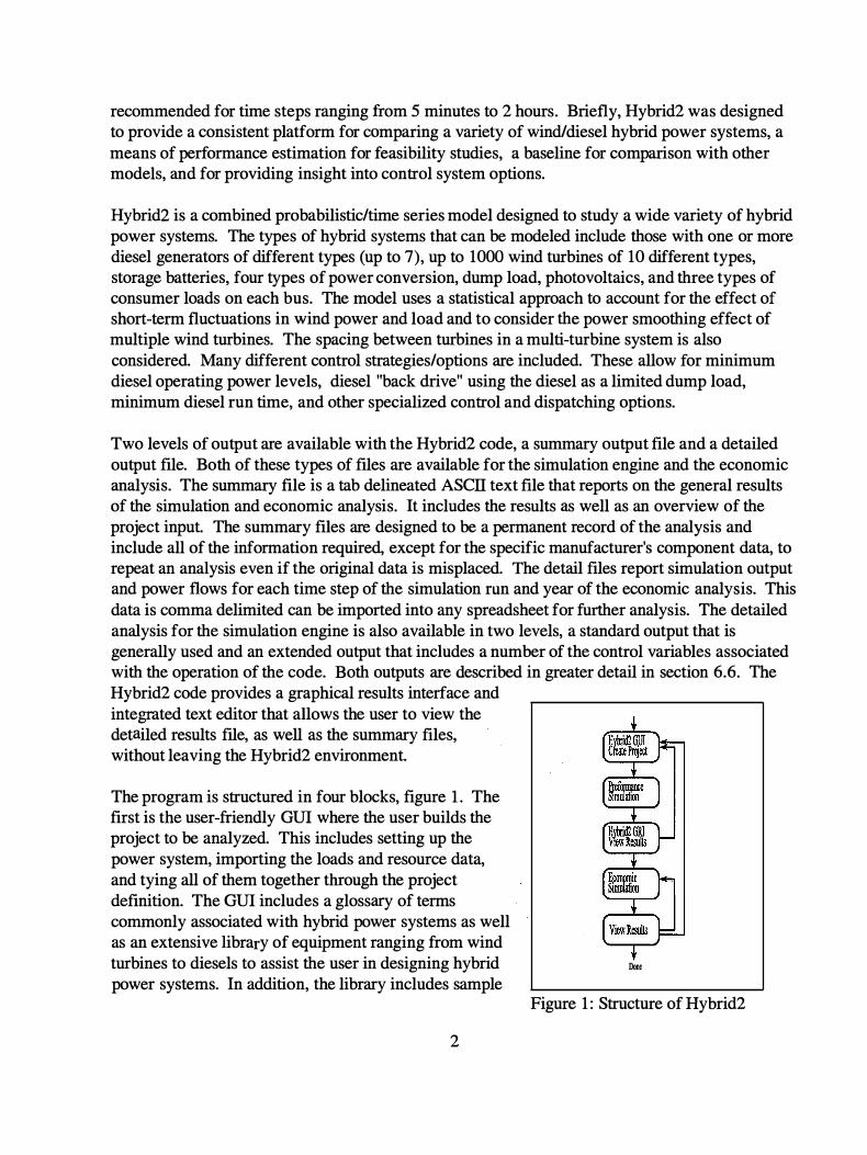
Engineering
Proceedings Energy Symposium
England Multi-Science Publishing Company LTD 1994
increasing the number of system consistency checks upgrading the users manual expanding the help functions provided with the code and including other modules such as microhydro and different combustion generators We hope that if you see potential areas of improvement that you will let us know
1 ) JF Manwell JG McGowan EI Baring-Gould WQ Jeffries WM Stein Hybrid Systems Modeling Development and Validation Wind Vol 18 No 5 p 241 Brentwood
2) EI Baring-Gould JF Manwell WQ Jeffries WM Stein Experimental Validation of the University of Massachusetts WindDiesel System Simulator Code HYBRIDl
New Orleans LA January 1994 of
the 13th ASME Wind
4
2 The Hybrid2 Package
21 Getting Started
Welcome to the Hybrid2 code The first task of a new Hybrid2 user is to check and insure that all of the components of the Hybrid2 package have been included and that the computer system that is to be used for the Hybrid2 code meets the requirements listed below It is important that the user read sections 22 Contents of the Hybrid2 Package and 23 Required Hardware before installing the code Section 24 Installation Procedure describes the code installation while section 25 Technical Support and Feedback describes the user support that is being provided to the user If you have any questions regarding what is included in your Hybrid2 package what computer configuration should be used to run Hybrid2 or if you have any problems with the installation procedure please feel free to call user support -- thats what we are here for
22 Contents of the Hybrid2 Package
The Hybrid2 software package that is provided includes both the Hybrid2 software and several other documents The package includes
bull The Hybrid2 Users Manual this document bull The Hybrid2 Installation Disks ( 3 disks) bull Copy of the Hybrid2 Theory Manual bull Copy of the initial model validation report
The Hybrid2 Users Manual this document describes all of the basic functions of the Hybrid2 code the installation process and how to create run and analyze a simulation using Hybrid2 The manual should answer most of the questions relating to the operation of the code and should be consulted first if any error arises If you are still having problems with the operation of the Hybrid2 code please feel free to contact user support for assistance
Hybrid2 is included on 3 installation disks Included with the Hybrid2 code are all of the required software drivers the on-line glossary and the library database of sample projects resource files power systems and components Instructions for installing the Hybrid2 code are given in section 24
The Hybrid2 theory manual describes the operation of the code in detail and allows interested users to become familiar with the algorithms used in the Hybrid2 code We strongly recommend that users familiarize themselves with the content of the theory manual even if they are not interested in the exact operation of the code The manual tells the user what assumptions have been made in the development of the code and indicates the importance of a number of the system parameters
The Hybrid2 validation report is the first installment of a series of Hybrid2 validations being conducted at NREL This fust report describes our plan for verifying the Hybrid2 model and the initial results The first validation report compares the Hybrid2 simulation of the FrZiya Island hybrid system to actual system performance data This validation is of a winddieselbattery
5
system and uses 17 days of 10 minute data collected at the site We feel strongly that for the Hybrid2 code to be used successfully in modeling potential hybrid power systems users must convince themselves of the models validation and therefore we are committed to that effort More information on the validation effort can be found in chapter 8
23 Required Hardware We have made an effort to keep the hardware requirements associated with the operation of the
To operate the Hybrid2 code the host must provide
bull An IBM or compatible PC This PC must be at least a 386 micro-processor with a math co-processor [The faster the speed of the processor the shorter the time required for each simulation run A 1 year simulation run for a winddieselbattery system on a 486-50 is approximately 25 minutes while on a Pentium 66 the simulation requires approximately 8 minutes ]
bull DOS operating system bull 1 Meg of Random Access Memory (RAM) bull 15 MB of free hard disk space Hybrid2 requires approximately 7 MB of memory but the
detailed simulation result files can be quite lengthy bull VGA video driver with 640 x 480 resolution bull Mouse bull 35 disc drive bull Microsoft Windows 31 or better (Hybrid2 will run with Windows95)
Hybrid2 is configured to function on most laptop computers
24 Installation Procedure
Hybrid2 code as low as possible Although we have not succeeded completely in this effort the level of hardware required is minimal compared to most software codes
Hybrid2 comes on 3 high density 35 disks The user should insert disk 1 into drive A or B and then from the windows file command run the lnstallexe program on Disk 1 The Hybrid2 installation software will prompt the user for a directory name The Hybrid2 directory must be placed on the first level of your computers main directory ( ie CHybrid2 ) However it can have any name CHy2 for example The installation software will also install an icon into your windows environment for easy access to the Hybrid2 model Following the installation procedure the Hybrid2 code can be run by selecting the code from your program directory or double clicking on the Hybrid2 icon Hybrid2 can be removed from your computer by running Hybrid2 uninstall program what will also be loaded into the Hybrid2 directory This program will remove any software drivers that were installed on your computer to run the Hybrid2 code Some users particularly users with laptops may need an independent version of a specific driver that cant be replaced during the installation procedure If this occurs a copy of the driver Threed V BX has been provided on disk 3 this will have to be copied while in DOS because it is used to operate windows The driver should be copied into the Windowssystem directory
6
Note for Windows95 Users The install program will prompt you to place the Hybrid2 subdirectory in CProgram FilesHybrid2 Hybrid2 must be placed in the root directory CHybrid2 and therefore you must edit the installation path accordingly
25 Technical Support and Feedback
Technical support to all users is being provided by the University of Massachusetts In addition any feedback bug report forms or just general comments about the software should be addressed there Since user support will not be constantly available we are recommending that most correspondence regarding problems should be completed via e-mail or fax The use of e-mail will allow for a quick response to potential problems as well as facilitate the distribution of relevant questions and responses to all beta testers regardless of who asked the question In this light we recommend that beta testers check their e-mail for any bug notices or further code clarifications on a regular basis User support will generally be available afternoons on Monday Wednesday and Friday for phone consultations
Technical Support questions should be directed to Utama Abdulwahid Renewable Energy Research Laboratory Department of Mechanical Engineering University of Massachusetts Amherst MA 01003 (415) 545-3916 (413) 545-1027 E-mail Hybrid2kiraecsumassedu
People interested in obtaining copies of Hybrid2 or additional information should contact Ian Baring-Gould NRELINWTC 1 6 17 Cole Blvd Golden CO 80401-3393 Phone (303) 384-7041 Fax (303) 384-6901 E-mail Hybrid2nrelgov
26 Conventions Names of individual screens windows or tabs are in Italics
Menu commands are in bold Buttons are shown in ltinequality bracketsgt File names and directories are shown in [square brackets]
7
3 Structure of the Hybrid2 code
31 Program structure Hybrid2 divides projects into five branches that extend out from the Hybrid2Project screen Each of these five branches are defined in a 4 level structure as shown in figure 2 The four levels are the Project level the Module level the Subsystem level and the ResourceLoadComponent level Every project will contain elements from each level and each level is inclusive of the elements in the lower levels
Project
Module
Sub-System
ResourceLoad Component Level
Figure 2 GUI Structure
The Project level consists of all of the information that defines the project in question The Project level specifies which modules are being used in the specific analysis and allows users to identify different modules that are to be used
The Module level defines the different elements of the project There are five modules which correspond to the five branches from the Project They are 1) Loads 2) SiteResource 3) Power System 4) Economics and 5) Base Case Diesel System Each module contains information that is specific to that area of the project The Loads and Base Case Diesel System Modules are unique because they are defined explicitly for each project The three other modules may be used in many different projects and therefore are saved independently of the project Each of the modules are described briefly below with a more in-depth description saved for later in this document
bull The Loads Module describes all of the loads for the community being modeled The type of loads and their names are specified in this module The actual loads are held in independent records that are inserted into the Loads Module as required This defines the particular combination of loads to be analyzed in the current project Load records
8
can be inserted in many different Load Modules More information on system loads can be found in section 7 1
bull The SiteResource Module specifies which resource files are going to be used in the analysis The different resource files available are the wind speed solar insulation and temperature In addition specific information about each of the resources andor the specific site are located in this module The siteresource module is also very dependent on the location of the analysis but it may contain resource data that was not collected at the specific site Unlike the loads module the siteresource module exists independently and can be inserted into a project as a unit Importing data and creating siteresource modules is described in detail in section 7 2
bull The Power System Module describes the specific power system that is to be used in the analysis The exact configuration of the power system its components and the control strategy are defined in this module As with the SiteResource Module the power system can be created as a unit and then inserted into any number of distinct projects The power system module is defined in depth in section 73
bull The Base Case Diesel System Module specifies all of the information used to define a preexisting diesel system if present or an all diesel system to compare with the hybrid power system Like the loads the base case module is linked to the project and can not be saved independently for use in more than one project The base case all-diesel system is described in section 7 4
bull The Economics Module contains all of the economic parameters that are required to perform an economic analysis The user is required to enter all of the cost information about system components and operation Because an economic analysis can be performed independently from the simulation engine the economics is saved independent from the project This module should be completed only after the power system has been completely defined The Economics Module is described in section 75
The Subsystem level is used to describe the different components of the same type that make up a power system Because the Power System can include multiple diesels wind turbines power converters solar modules and batteries the subsystem is used to define the parameters that are specific to each type of component An example of such a subsystem would be a PV array A PV array is made up of a number of off-the-shelf PV modules placed in a certain configuration with certain array parameters The subsystem specifies which module will be used and the array configuration but it does not describe the specific characteristics of the module itself
The ResourceLoadComponent level represents the lowest level in the Hybrid2 hierarchy System component files include the parameters of each piece of equipment like a specific wind turbine PV module diesel and battery The Component file contains all of the information to
9
describe how that single piece of equipment functions its efficiencies and cost The load records in this level describe the specified type of community load whether AC primary load or DC optional load These files may be either time series in nature thus including one value for each time step in the simulation or a standard file that provides information that is used for the whole simulation The Resourcemiddot data of the Component level includes all of the time series information for each resource that is to be used The resource files also include information about the type of data and the conditions in which it was collected
The Graphical User Interface GUI allows the user to define each of the modules in any order The only restriction is that only one module can be worked on at a time and most of the modules must be completed in full before it can be exited This is done to insure that a module is not left partially completed and then included in a simulation run The only exception to this is the Power System module that may be left before being completed This is allowed because the Hybrid2 code performs a consistency check on the project before a simulation is performed and inconsistencies in the power system will cause the simulation to be canceled and the user returned to the Run Simulation window We urge the user to quickly review each project before running a simulation to insure that everything is in order before the simulation is started
The first step of creating a project is to select ltNewgt on the project screen and then name the project The user should then specify the simulation time step in the lower left comer of the project screen All of the time series data being used in the project will have to use the same time-series time step We recommend that the user first define the loads using the Loads Module then proceed to the SiteResource Module both of which use data dependent on the specific site in question The user should then define the power system using the Power System Module The all-diesel Base Case and Economics Module can be completed last if those analysis are going to be conducted A project must contain Loads SiteResource information and a functioning Power System before a simulation can be conducted The user may also define components and import data into the library without including them in any specific project
The Hybrid2 simulation engine uses ASCII test files to import all of the information needed to perform a simulation The GUI currently writes out text files that the simulation engine uses in performing the simulation All of the files used are saved with the name hy2sim and are saved in the hy2sim sub-directory of the Hybrid2 directory The Hybrid2 code deletes all of these files whenever a new simulation is performed so that the user does not need to worry about deleting them However this function allows the user to maintain text copies of any of the records in the database by printing these files before they are deleted This function is described in more detail in the ImportExport section of this manual
32 Units Units are defined in Hybrid2 in various places and although this may seem confusing it was added to allow versatility and is actually quite simple Units are defined on both the Module level and the Component level In this fashion the units used to define the parameters in the ResourceSite Module can actually be different from the units in the Resource Component For
10
example a ResourceSite Module can be defined using metric parameters while the wind speed resource is in English and the solar insolation is also in metric The information on the Wind
Resource tab will be displayed in English while the rest of the parameters on the ResourceSite
screen will be displayed in Metric units This function is duplicated in the Base case and Power System Modules
33 Directory Structure The Hybrid2 code is linked to a Microsoft Access database that records all of the library in a data base form This separates the user from the need to maintain strict directories with regard to the project under consideration as was the case in HYBRID 1 code The only data sets that are not included in a database form are all of the time series data records The files for all of the time series data are held in a directory called [ts_data] This directory must not be deleted or moved because the database will be unable to access that time series data The Hybrid2 code will automatically delete any time series data that has been removed by the user from the Hybrid2 library The second directory used by Hybrid2 is the [h2sim] directory This directory must also remain intact and is used as the default directory for all code input and output Because of the quantity of data that is generated by Hybrid2 we recommend that the users create and maintain a directory structure to separate the different project simulations they are working on Hybrid2 result files a short text file describing the simulations and optionally a backup of the project may be stored in separate sub-directories of the Hybrid2 root directory for future use This will keep the Hybrid2 directory clean and reduce the risk of accidentally overwriting any Hybrid2 result files
34 Code Speed On older computer systems the Hybrid2 code may run slowly The GUI will talk a long time to move between windows and any simulation will take a long time to be conducted The speed of the GUI can be improved by the addition of more internal memory but short of that nothing can be done to increase the speed of the GUI
The simulation itself is very computational intensive and can require a great deal of time on older computer systems We are presently unsure of what portions of the code are causing the slow down of the simulation engine disk access speed internal memory or cpu computational speed in some iterative loops The speed of the code is greatly dependent on the computer Some yearly simulations can take minutes of some computers and nearly an hour on others There are a few thinks that the user can keep in mind if simulations are requiring too much time 1) Do not create a detailed output file for all the simulation runs that you are conducting When conducting repeated analysis use the summery file only and save the detailed file once you have narrowed the scope of you analysis This will reduce the amount of disk access required by the simulation for each time step and can decrease the run time of the simulation by about 20 2) When running a simulation for a year run a complete analysis for the year andthen see what season(s) or month(s) will drive the system design For example a single month with low wind speeds and a large load may well drive the battery bank size Run all of the simulations to finalize the design only on this time period instead of the whole year Once you are satisfied that
1 1
the system will preform during the worst case season then complete a final simulation for the whole year Typical years can also be simulated using a week from each season or a week from each month instead of running the complete year for each simulation
12
4 Menu Commands The following is a description of the elements in the menu bar of the Hybrid2Project window
41 File Program functions ExportImport Projects This allows the user to select a project and export it to a separate
database file for transport The user may also import a file from another Hybrid2 database by using the import function See Section 53 for a description of project importing and exporting
Splash Returns the user to the introduction window of Hybrid2 Exit Exits and closes the Hybrid2 code
42 Run The means for running a Hybrid2 simulation or an economic analysis Simulation Allows the user to conduct a Hybrid2 simulation See Section 63 for more
information on rupning a simulation Economics Allows the user to conduct a Hybrid2 economic analysis See Section 64 for more
information on running an economic analysis
43 Results Methods for viewing results Graphics Opens the Hybrid2 graphical results interface which allows users to view the
detailed simulation results file while still in Hybrid2 Please consult Section 54 for more information regarding the graphics capability of Hybrid2
Editor Allows the user to view any of the summary files while still in the Hybrid2 interface This feature is discussed in Section 55 of this manual
44 Help Help services supplied with Hybrid2 Glossary Access to the Hybrid2 glossary where a user may find the definitions of frequently
used hybrid power system terms The glossary is also accessed by double clicking with the right mouse button on the background of any Hybrid2 window See Section 52 for a description of the Hybrid2 Glossary
Technical Assist Provides information on accessing Hybrid2 technical assistance Credit Credits for the people who have been instrumental in the design coding and
development of Hybrid2
13
I
L
I L
5 Program Features
51 Library The Hybrid2 code includes a large number of records that make up a library of files for use in the project development The Hybrid2 library includes sample projects time series data sample power systems and manufacturers data on system components The user may use the library records modify library records or enter data for components not included in the NREL distribution library The records may be used in any number of projects simultaneously and can be deleted by the user The user may choose to edit an existing library record to add an additional feature or update performance information Edits to a record are permanent that is the original data that has been replaced is lost Therefore to edit a record the user must first copy the record and then make any modifications to that copy All user records become part of the library and can be used at a later date and in multiple projects
All of the components of the NREL distribution library are read only records and cannot be replaced altered or deleted by the user The entries can be copied and then modified but the user will be prompted to assign a new name to the record in question This procedure insures the accuracy of the distribution library If a user is having problems conducting a simulation data from the NREL library should be used to insure that the input parameters to the simulator are accurate All of the data provided by NREL were taken from manufacturers specifications Users should take care to manage the size of the library because although each record does not take much space many records can slow down the operation of the user interface
Each of the library records for the specific type of module resource or component is accessible by clicking the left mouse button on the underlined downward facing arrow on the window in question Hybrid2 uses a phrase to identify each of the records in the library The record titles should be as distinct and descriptive as possible so the user can easily identify the different records in their libraries Two records can not have the same title description
52 Glossary A glossary of terms is provided to assist the user in the construction of hybrid power systems The glossary provides a definition for all of the inputs required for the Hybrid2 code as well as terms that are commonly associated with hybrid power systems In addition to definitions the glossary provides were applicable an example default values recommended ranges and hard limits for all code input parameters The glossary is accessible on the Hybrid2Project screen under the Help menu or by double clicking the right mouse button on the background of any Hybrid2 screen
53 ImportExport Function The Hybrid2 GUI contains an importexport function that allows the user to transfer projects from one computer to another or it can be a means of backing up projects that are not presently being used in Hybrid2 Hybrid2 creates a Microsoft Access transitional database that can be merged into another copy of Hybrid2 The importexport functions are accessible from the
14
Hybrid2Project screen under the File label of the Menu bar Users are allowed to import or export one complete project at a time
When importing a project a few things need to be kept in mind Since record descriptions are used as identifiers each record of the same type the PV modules for example must have a unique description If any of the records being imported have the same description as one already existing in the database Hybrid2 will add the word IMPORT to the title Hybrid2 will only allow one imported copy of a specific record into the database If an imported copy of a record already exists the new record will not be imported For this reason after importing a project the user should check to see if any duplicate records were made If any records are duplicates we recommend that they be replaced in the project by the original record already in the library and then the imported duplicate deleted This will ensure that the Hybrid2 database will not be filled with duplicate records
Exporting projects serve two functions The primary use will be to transfer projects from one copy of Hybrid2 to another The second use of the exporting function will be to back up projects that are not currently being worked with The exported project may then be deleted from Hybrid2 which will free up space in the database but still allows the project to be available if needed When exporting projects the user must specify the file name for the project to be saved as and select a project to be exported When a project is exported all of the supporting records are also exported into the transition database To export a single file the user will need to attach to a dummy project and then export that project
The user may also wish to print out files from the database A printing function is not presently available although the user may save the Hybrid2 simulation engine input files before they are deleted by Hybrid2 As noted in the Program Structure section of this manual the Hybrid2 GUI writes out text files that the simulation engine reads to run the simulation The GUI will overwrite these files every time a simulation is performed Because these files are simple text files the user may start a simulation run and after the files are written select the ltNogt option to not run the simulation The GUI has already written the specified files and the user may -- using any text editor -- open copy andor save them under a different name All of these files have the name h2sim but the file extensions are different for each type of record -- project power system or component -- they describe Appendix A contains a listing of the file extensions for each type of Hybrid2 record
54 Graphical Results Interface The Hybrid2 code includes a Graphical Results Interface (GRI) that allows the user to view the results of a simulation from within the Hybrid2 code The GRI can be opened from the Results
menu of the Hybrid2Project screen It can be used to quickly look at the results of previous simulation runs or a run just completed Once in the GRI the user will need to open a detailed results file using the Open command from the File menu tab Plots created with the graphics package can be copied and pasted into reports or other documents The GRI can plot more than one time series but is limited to 6000 total data points The GRI time series index assumes the
15
time step is in hours and thus the data is plotted as such although it is a series plot and can have any units The GRI uses the detailed output record and thus will only work if one is generated Users should note that the GRI can be rather slow if large data sets are being examined but it allows faster access to the detailed results file than most spreadsheet applications
55 Text Editor Hybrid2 includes a simple text editor that can be used for viewing any of the summary results files created by Hybrid2 without switching to another code Because the imbedded text editor has a limited buffer size of 36000 characters users should be wary of loading time series data files into the editor
16
6 Operating The Hybrid2 Code
61 Starting Hybrid2
The Hybrid2 software can be started either by double clicking on the Hybrid2 icon from the Windows Program Manager or double clicking on the Hybrid2exe file in the Windows File ManagerExplorer
62 Building a project
Prior to executing a simulation the user must construct the project and power system for the site being analyzed Projects can be constructed in three ways -- piecing together records from the Hybrid2 library modifying library files andor constructing new records from scratch Each of these three options will likely be used in creating an actual project The GUI simplifies this process using a windows environment to give the user easy access to all of the parameters that need to be defined To construct a functioning project the user must fill in all of the data requested by Hybrid2
The Hybrid2 library distributed by NREL includes records of every type to allow the user to select pre-defined components for use in the projects The user may select any of the records from the pull-down menus associated with those systems and insert them in their project using the ltInsertgt button As the user modifies or creates new records the work becomes part of the library to allow for use at a later date If the user has a completely new system he or she may create new records or modify existing records using the ltNewgt or ltCopygt buttons respectively As stated before any modifications made to a record are final and cannot be undone To insure that the original data is not lost the user must frrst copy a record and then make any modifications Once a record has been selected it must be inserted into the project module or subsystem using ltInsertgt Any record that has a record description must be inserted into a project for it to be included in the analysis If the user does not wish to include a new record in a project she or he will just not insert it into the project The ltRemovegt button is the opposite of insert and will remove the record specified from the project A more complete description of creating a project in Hybrid2 is described in section 7
63 How to run a simulation
A simulation is executed by selecting the option Simulation under the Run menu bar of the Hybrid2Project screen The simulation run window prompts the user to enter data relevant to the simulation run The user is also asked to specify the type of output and the file names for the output files The program also asks if the user plans to perform an economic evaluation based on the simulation and if that is to be done in conjunction with the simulation run The simulation engine creates a data file containing all of the performance information used for the economic evaluation only if requested to do so by the user An economic evaluation can not be completed without the simulation performance data Therefore if an economic evaluation is to be completed using a particular simulation run a simulation performance output file must be completed or an additional simulation run will be required After the type and file name of output files have been specified the user simply clicks the ltOKgt button to start a simulation A
17
consistency check is performed on the project as the first step of the simulation processes If the check fails the user is returned to the Run Simulation window with an error message indicating the system conflict discrepancy andor emission Any errors in the project will have to be corrected before a simulation will run successfully Once the consistency check has passed the simulation and if applicable the economics analysis will be conducted A progress bar has been provided to allow the user to keep track of the simulation progress When the simulation is completed and the result files are printed the user is returned to the Run Simulation window
64 How to run the economics separately An economic analysis can be completed by in two ways either selecting the option Economics
under the Run menu bar of the Hybrid2Project screen or by specifying that an analysis is to be completed as part of a performance simulation run Because the user may wish to conduct more than one economic analysis for a given simulation the economics module of the Hybrid2 code was separated from the main simulation engine If economic evaluations are to be completed for a specific simulation run the user must initially specify that a Simulation Economic Parameter File be constructed when running a performance simulation This can be done either by selecting the Run Economics Now or Run Economics Later choice from the Run Simulation
window prior to running the simulation This will cause the Hybrid2 to create a simulation performance file that is used by the Economics Module As described in Section 75 Economic Module this file contains all of the system performance data that is needed to complete an economic evaluation The other piece of information required by the simulation to run an economics analysis is the economic input record created by the user in the GUI An economic analysis is completed by specifying the Simulation Economic Parameter File to evaluate and the project economic input record from the Hybrid2 database The user must then select the type of output wanted and specify the file names for the appropriate files The Economics Module creates two types of output files a summary report and a project cash flow report The summary report is a text file that includes all of the economic indicators like years to payback internal rate of return present worth and annualized system expenses The summary report also provides a single cash flow for the project The detailed output file is a spreadsheet formatted text file that provides a cash flow analysis for many system parameters Cash flows for yearly income specific expenses system profits and the replacement cost of various components are given for each year of the projects economic life The economic input record in the database can be modified and another economic evaluation completed to perform a parametric analysis on various economic considerations This process can be repeated either saving different versions of the economic input file or modifying a single record The summary report constructed by the economic module records all of the input provided by the user and thus will act as a log of the inputs for each particular analysis
65 Importing time series data Time series data is used to define primary loads as well as wind solar and temperature resources Some time series data has been included as part of the Hybrid2 library but the user will likely want to include their own data in the analysis of certain projects This is done using the ltImportgt button located on the window tabs of any windows allowing data importing
18
Presently any data that is imported into Hybrid2 must be put in the proper form before the import can be completed this is discussed below This manipulation can be done in any word processor or spreadsheet although the data must be saved in a text format to be imported into the database Before importing data the user needs to create a new record for this data using the ltNewgt button and fill in all of the information requested including the data time step This data represents a specific place time and conditions Although it is useable in other locations the original condition in which the data was collected should not be changed The user should then using the left mouse button press the ltImportgt button A file dialog box will appear prompting the user to select the file of time series data Once the data file is selected the user will be prompted whether the data is in metric or English units and then it will be copied into the [ts_data] sub-directory of the Hybrid2 directory Once imported it is recommended that the data be plotted and the statistics noted to insure that all of the data arrived successfully The graphics will only print and calculate the statistics on the first 10000 points of data although the whole data set is still present and can be used in a simulation We also recommend that the user take advantage of the notes field to include important information about the data such as how it was collected calibration when it was collected and the name of a contact people if applicable who collected the data Once imported the time series data becomes part of the library and can be used in any project until it is deleted by the user
To import data it first must be placed in the proper form data should be in a single column followed by a line feed and a carriage return Example 2234 ltLFgtltCRgt
2454 ltLFgtltCRgt
If a standard deviation for each time step is known for wind and load time series data and is being included it must be specified in the time series file next to the corresponding average separated by several spaces Example 2234 3245 ltCRgtltLFgt
2454 3933 ltCRgtltLFgt
In this example 2234 is the average for the time step and 3245 is the standard deviation of the data over that average The data file should not contain a header or any special characters and must be saved in a text format The data file can be located anywhere on your system and will not be altered or deleted by the importing process
One limitation of the Hybrid2 software is that all of the time series data both resource and load that is to be used in the same project must have the same time-step or averaging interval This time-step must also be used as the Simulation Time Step during simulation runs In addition all of the time series data must be synchronized not only daily but down to the time step Obviously if the load and resource data for a PV village system are 12 hours out of phase with the peak solar output being generated by the simulator at midnight load time the results of the simulation will be in error
19
66 Description of the simulation output Hybrid2 provides output from both the simulation engine and the economic package Two forms of output for each portion of the code are provided The first file is a summary file while the second is a detailed output file
The summary output file for the simulation engine includes summations of all of the important power flows performance of individual components total fuel usage and fuel savings The summary file also includes enough information to recreate the project This file allows the user to determine the performance of the modeled system and if applicable compare it to the base case all-diesel system Using the summary file the user can determine possible revisions to improve the performance of the hybrid system The summary file is a tab-delimited text file that can be viewed and formatted in any word processing software or the text editor provided with Hybrid2
The detailed file is a space-delimited text file that includes time step by time step values for each important parameter associated with the hybrid system The file can be viewed in the Hybrid2 Graphical Result Interface or imported into a standard spreadsheet Two levels of detailed output are available the standard detailed file includes parameters such as power diesel fuel use unmet load system losses and battery state of charge This level of detail will be sufficient for most users to determine interactions between different components and the effectiveness of the control strategy selected by the user The extended time series file includes all of the time series data specified in the standard version as well as parameters like the maximum and minimum net loads ambient temperature horizontal solar insolation and losses associated with the discharge of a battery bank The extended file is probably most useful in determining the accuracy of detailed performance data system control logic and detailed loss calculations Both the standard and extended detailed output files will only provide results for components that are included in the project being simulated This cuts down on the size of the files but they depending on the complexity of the system and length of the simulation can be more than two megabyte in size for a 1-year simulation Because of the size of the detailed output files users should take care to delete any unneeded or outdated time series output files Appendix B provides a description of each time series output provided by the simulation engine
The output for the economics package also comes in a summary and detailed form The summary file provides all of the economic figures of merit such as payback period internal rate of return and all of the economic input parameters that go into the analysis The detailed output file includes a year-by-year breakdown or revenues expenses and overhaul expense schedules The summary file is a tab-delimited text file while the detailed file is a comma-delimited text file More information on the output of the economics package is provided in the Economics Section of this document section 75 as well as the Hybrid2 Theory Manual
20
7 Creating a Project Creating a project is a task that we have tried to make as simple as possible The use of the Hybrid2 library will allow the user to select components or even whole modules without needing to worry about any of the system details If a more accurate analysis is needed all of the parameters can be edited to more closely model the site in question We recommend that the user follow these instructions to create the project
The first step of creating a project is to select ltNewgt on the Hybrid2Project screen and then name the project The user should then specify the simulation time step in the lower left comer of the project screen All of the time series data being used in the project will have to use the same time series time step This time step must also be used as the Simulation Time Step during simulation runs As an additional requirement all of the time series data must be synchronized not only daily but down to the time step
To Cofy the current Projec using a new name
Delete the Project
Start a new Project
Notes about the Project
The Simulation time step for the Project
The different Modules that make up a Project
71 Loads Module Hybrid2 allows for a system to contain loads on both the AC andor DC buses The code also provides the use of three types of loads -- primary deferrable and optional Primary loads are time series dependent while deferrable and optional loads are specified for all or part of the simulation period A primary matrix load is a time-series load generated by Hybrid2 based on representative values input by the user Each of the loads are defined on an individual tab which can be accessed by clicking on the tab with the left button of your mouse The Hybrid2 library is accessible by clicking the left mouse button on the underlined down arrow next to the load
2 1
description Each of the library records can then be selected using the mouse The time series data can be viewed using the ltPlotgt button on that tab Once a load has been selected it should be inserted into the project by clicking the ltInsertgt button on that specific tab The description of the load will appear in the appropriate box in the top portion of the loads module To remove a load from your project simply press the appropriate ltRemovegt button with your mouse All the AC and DC deferable and optional loads are defined by a series of load specifications Each load is defined as a separate line in the specific grid and there can be more then one load of each type All the different types of loads are discussed in detail below Importing data for the primary loads is done with the ltImportgt button and is discussed below Once all of the loads for your particular site have been selected clicking on the ltOKgt button will return the user to the Hybrid2Project screen
Loads in Project
Remove from Project
Load Tabs
Plot Function
Data Import
Insert into Project
Data Statistics
Done Defining Loads
711 Primary loads The primary load is used to specify the on-demand load of the community under analysis The primary load is made up of time series data in which each time step of the simulation has a specified load The primary load can also contain an inter-time step variability or standard deviation The primary load must be supported by the power system Any load that is not met and the amount of time for which the load was not met is reported in the summary output file If a project includes optional or deferrable loads on either bus a primary load must be included The primary load is required because if the deferable load has not been met in its required period the deferable load is transferred to the primary load The user can specify a primary load record that consists of zeros (in other words no load) to satisfy this demand
22
The inter-time step variability within the load can be specified in one of three ways A standard deviation can be specified for each time step of the load this value forms another string of time series input One value for the standard deviation can be specified for the whole data set An average variability in the load can be used instead of this standard deviation This also applies to the entire data set
If detailed time series data is available they can be imported into the library using the import function on the Primary load tabs of the loads module Importing data is described in section 53 Importing time series data Load time series data can include either an average value or an average and the corresponding standard deviation of the data for that average
7 12 Primary Matrix Load The second way to create a time series load is by using the primary load matrix function incorporated into the Hybrid2 code This matrix allows the user to specify
Plot of hour average
Plot of monthly scale factor
Load Statistics
Monthly scale factor starting with first month of the data
Daily load profile starting with the hour from 1200 PM to 1 00 AM
the average load for each hour of a typical day and a monthly scale factor for each month of the year The Hybrid2 code then uses the hour average and scaler to create a yearly load profile
23
The user is still required to specify the average variability for the load The Hybrid2 code includes a daily load profile generator that user can access to determine a daily load profile in the Hybrid2 matrix load generator called Load_genxls This load generator uses an Excel spreadsheet and was originally created by Sergio Castedo of the American Wind Energy Association Using this external package the user specifies the different power needs for a community defined by the number of specific energy devices their rated power and the number of hours of operation daily This data set is used to generate a daily load profile that can be used in Hybrid2 to generate a yearly load profile General operating instructions are provided with the software
If the user has more available data than is needed for the matrix load generator it may be better to create a load time series using a spreadsheet and then import that data as a titpe series This method although more time consuming will result in more accurate performance estimates if a single daily load profile does not capture the actual community load Examples of such loads would be large variations in the daily load over a week -- such as weekend loads or market days -- and places with wide variations in the daily load profile because of the seasons -- as may be found in the far north or south In places such as these the user will have to decide if the increased accuracy of the simulation is worth the extra time used in creating a primary load profile outside on the Hybrid2 environment
713 Deferrable Load A deferrable load is an electrical load that contains a limited amount of storage and thus allows some leeway in when it is fulfilled Deferrable loads may be postponed for some time while waiting to see if excess energy from renewable energy sources or from diesels forced to run at a minimum can provide the required energy If the deferrable load is not met in its time period the load is treated as a Primary Load and must be supplied immediately Any failure to meet the load constitutes a power outage Examples of a deferrable load are an ice maker or water cistern that must be filled on a regular basis The time of day the load is meet however is of little concern Two types of deferrable loads have been designed in Hybrid2 -- the block and the running average method Block average deferrable loads have a fixed time duration over which the load must be met For example every 24 hours the pump needs to be run at rated power for 8 hours The user may specify a number of Block average loads all of which run sequentially with the last one defined operating for the remainder of the simulation Each deferable load is operated for the same period of time The running average method fills the load and then restarts the clock saying now we have 16 hours before we may need to start the pump The running average method allows for concurrent deferable loads with different deferral period Both of these methods are described in the Hybrid2 theory manual and code glossary Deferrable loads can be on both the AC andor DC busses simultaneously or one bus alone If a deferrable load is present on a bus that bus must also contain a primary load Each load is defined by four parameters bull Rated power of each device bull Duty cycle of its operation which describes the amount of time it must operate over its
Deferral period
24
bull Deferral period which is how often the load must be filled For Block average loads only one deferral period is defined for all of the loads Different Deferral Periods can be specified for each load when using the Running average method
bull Part or full load operation of the deviceeacuteMore detailed descriptions of each parameter are given in the Hybrid2 glossary accessible by double clicking the right mouse button on the background of the main window
Two defined loads
Add an additional load
Defines which type of load to use for Project Delete the highlighted load
714 Optional Load An optional load represents a useful application for excess electricity Here excess energy is the energy that is left after supply of primary load battery storage and any deferrable loads Loads can be defined that use this energy instead of it being wasted In the event that excess energy is not available to meet such a load one of two circumstances will apply the application is a need that may be met by other means or the application is a convenience rather than a need and may be neglected indefinitely with no harm being done The value of optional energy is that waste energy which would normally have to be dissipated is used to replace another source for power generation or heating An example of an optional load
25
is a water-heating system featuring both an electrical heating element and a combustible fuel When extra power is available it is used to heat water instead of being dissipated using a dump load The use of the excess power has a monetary value because it replaced the fuel that would have been expended to heat the water Optional loads can be on both the AC andor DC buses simultaneously or on one bus alone The optional load is defined in the same manner as the deferrable load except that only one load on each bus can be active at one time Multiple optional loads can be defined but they are fulfilled in sequence with each one being fulfilled for the duration period specified by the user An example of an optional load could be space heating for a northern community One Operational Load D11ration is defined for all of the loads ( say a month or 730 hours) and then 12 optional loads are defined using different duty cycles to describe the different seasonal heating requirements Hybrid2 will start with the first optional load defined and run that for the specified Operational Load Duration and then it will move to the next optional load If no additional optional loads are defined and the simulation has not been completed Hybrid2 will use the last optional load for the remainder of the simulation
Use of deferrable and optional loads are forms of load management and can greatly enhance the quantity of the loads that can be served by renewable energy and thereby the use of renewable energy Power used for optional and deferrable loads can have economic value when it replaces other power sources or can be sold It also allows the power system to use excess power when it is available instead of wasting the power through the use of a power dump This increases the system flexibility and as efficiency
72 The SiteResource Module and Resource Data
The SiteResource Module allows the user to create a combination of data and site parameters to include in different projects The resource data records include information specific to the collection of the data whereas the SiteResource Module includes parameters that are specific to the particular site For example the SiteResource Module shown below is for Cuttyhunk Island although the wind resource data was collected at Block Island about 35 miles to the WestSouthwest The average wind resource will likely be the same but the local site conditions and turbulence may well differ The SiteResource module is saved as an independent record and may be used in any number of different projects This was done so that the same site record may be used in a number of different but similar locations such as the numerous islands along the coast of Massachusetts and Rhode Island
Three types of resource input data can be used in simulation runs of Hybrid2 -- wind speed solar insulation and ambient temperature The type of resource data that will be required will depend on the type of system being modeled Accurate time series resource data are of great importance in obtaining an accurate simulation of the system therefore if data from the actual site in question are available they should be used Numerous techniques can be used to obtain resource data some of which are discussed below
26
Time series data of wind (including fluctuations) insolation ambient temperature may be imported into the Hybrid2 database from the appropriate tab on the SiteResource screen The methods of importing data are covered in section 65 Importing Time Series Data Before the data can be imported into the Hybrid2 database it must be put in the proper form as discussed in section 65
Site record included in the Project Remove a Site record from the project
Insert a Site record into the project
Units of Site record
Remove time series (TS) data from Site
TS data in Site
TS Data Tab
Import TS data
Plot TS data
Insert TS date into site record
Plot of TS data
Units of time series (TS) data Data Statistics (only after plotting)
To Wind Resource Parameter window
Wind speed time series data can include not only the time interval data but also the standard deviation of the wind speed over that interval If a standard deviation is not available the user may enter an average value for the standard deviation or the average variability to be used in each discreet time step When a standard deviation is included with the time series data it should be prepared in a text form with each line containing the average value of wind speed several spaces and the standard deviation of the wind speed for that time step
27
The user is also required to include a number of parameters associated with the data that is being used These parameters -- such as anemometer height and pyronometer location are important characteristics of the data and should be reported properly We also recommend that the user take advantage of the notes field to include important information about the data -- such as how they were collected and calibrated when they were collected and the name of a contact person if applicable who collected the data Because the time series data was taken under specific conditions once this record has been created the data can not be altered or copied Values for the wind speed can be scaled to allow the time series data to be used with a different yearly average at another site for which the same wind speed distribution is judged to be appropriate
If no detailed resource data can be obtained for the site the user will have to be more creative and careful about the data that are used for the simulation There are a number of approaches that can be used to generate resource data but they all depend on the amount of data available from the site in question The Hybrid2 library contains a number of wind time series data sets from various places in various climate regions Most of these data sets contain only 6048 hours of data 21 days per month for 1 2 months This was done because of incomplete data and worries of using wind speed synthesis routines on large portions of missing data If the user only has a yearly average for wind speed the data file that most closely typifies the location of the site could be used with the wind speed scale factor used to adjust the average wind speed to that of the site If monthly averages are known the user could print out one of the data sets as described in the ImportExport section of this document modify the monthly averages using a spreadsheet and then import the data back into Hybrid2 for the simulation In addition the wind resource parameters could be modified to better model the turbulence spacing and wind shear conditions at the site in question
Solar insolation and ambient temperature resource data are also included in the Hybrid2 library Solar insolation and temperature data are usually easier to obtain because local topography will have a much smaller effect than is seen with wind data Insolation and temperature data from an airport located 40 miles away are not likely to vary substantially from that at the site in question However local terrain conditions may have a great effect on the local wind speed and thus any wind data from the airport may be virtually useless The creation of resource data is very complicated and great care must be taken in determining what data to use and what errors should be expected from their use It should be clear to anybody using this code that an expertly designed system may fail miserably if the resource data used for the design is not accurate The purpose of this manual is not a guide to resource assessment and therefore interested users should consult the reference section of this chapter for more information on this subject But we recommend that a system should not be installed without some amount of reasonable data from a site in close proximity to the site under consideration
73 Power Systems
The Power System Module in Hybrid2 allows the user to create or specify a power system to be included in a project The power system is based on a three-bus grid that includes an AC DC and shaft bus system Specific types of hardware components are then included in each
28
subsystem that is attached to one of the buses Converters can be placed between the two buses and a control strategy can be defined to describe the interaction between the different components The arrows on the Power System Module screen indicate the flow of power from the devices through the grid and act as a simple system one line diagram
Like the Siteresource records the power system is defined and named separately and can be included in many different projects The library of different power systems can be seen by clicking on the downward arrow with the line underneath just to the right of the power system description
Sub-systems of the Power System
To remove the Power System the project
Make copy of PS
Create a new PS
Delete the current PS
Insert the current PS Into the current Project
PS notes Arrows indicate power flow
To define the Dispatch Strategy
The loads connected to the current Project
The subsystem is used to describe which specific component of each type and their quantities is being included in the power system The components describe a specific piece of equipment like a wind turbine or diesel engine Basically the components are independent pieces of equipment that are combined using the subsystems to create the power system An example of the difference between the subsystem and the components is found when defining a PV array Each
29
operation specific
PV module is defined as a component and then included in the PV array subsystem The subsystem describes the number of modules in the array the presence of a maximum power point tracker any array losses and the type of rack or tracker on which the modules are installed The component on the other hand describes the operation of the specific module -- such as the amount of power it will produce the module voltage and the module temperature coefficients Each different Subsystem is defined by clicking the appropriate button with the left mouse button selecting the desired Components and their number defining any required system parameters and then returning to the Power system window
PV module that makes up the PV array Number of Components and configurations that make up the PV array
Remove the Component from the Sub-System
The Sub-System defmes what is in the Power System
The Component defmes the
of a peace of
hardware
Insert Component Access to Component library into the Sub-System
731 Configurations Many different types of hybrid power system configurations are allowed using the Hybrid2 code Systems can contain none or multiple wind turbines on either or both buses none or multiple diesels and PV on one bus at a time battery storage and a dump load A number of different power conversion options have also been provided The dispatch strategy that is used will greatly depend on the system configuration and therefore should be one of the final elements within the power system to be completed The type of power system will also depend on the type of renewable resource available and the nature of the loads For example a
30
telecommunication repeater station in northern location that will be served using DC power where the only resource is wind would not contain PV In addition the power system should be based on a DC bus because the load is strictly on the DC bus Any configuration not violating the restrictions described in Configuration Restrictions section 732 below is allowed
7 32 Configuration restrictions A number of system configuration restrictions that have been imposed by the structure of the model These restrictions are also based on the desirable system architecture so that impossible or impractical systems can not be designed There are six general system restrictions
Diesels can only be on one bus A power system can not have a combination of diesels on different buses as well as the shaft bus
Photovoltaics are only allowed on one bus at a time Power systems can not have redundant power converters A power system may have only
one power converter in each direction This would prohibit configurations that would include for example an inverter and a rotary converter
A power system that uses the DC bus must include battery storage Integral to the DC bus is a voltage defined by these batteries
The battery bank voltage must be between 65 and 85 of the DC PV array voltage if a Maximum Power Point Tracker (MPPT) is not being used If this is not the case errors in voltage matching between the battery and a DC PV array may result
A system with a coupled diesel present must include a rotary converter of approximately equal rating
A small number of other simulation restrictions are also included such as the need for a control strategy if diesels or batteries are included in the system These restrictions do not limit the configuration of power systems being modeled The user will be warned of these restrictions when in the GUI
733 Components The power system is made up of a combination of components each of which is specified by a set of parameters particular to that component The components may either be selected by the user from the library pull down menus or created by the user All of the information required to define a component should be readily available from the component manufacturer although a little prodding may be necessary This section describes each of the components and the information that is required to define them
7331 Wind Turbine Hybrid2 divides wind turbines into two types AC and DC DC turbines are usually smaller in size under 20 kW and will most likely be used in smaller systems AC turbines are larger ranging from 10 kW up to 5 MW although AC turbines in the range of 10 to 250 kW will most likely be used in hybrid power systems Turbines are defined in Hybrid2 mainly by their power curve rated power and hub height Therefore most types of conventional wind turbines can be modeled The power generation by the turbine is determined by the wind speed and the power curve entered for the turbine Several adjustments are made to the power
3 1
informatio11 manmacture
J C9py wtfh
Graphi the component
Two Components included in Sub-system
The number of each specific Component in Sub-system
Su J lfton the same for all Components of this type
Access to Component Library
Component a new name
Insert Component into Sub-system
Delete Component
Defme new Comp
depends on
Delete data from grid Component available from Component Add data to grid
and wind speed because of differences in heights between the turbine and anemometer power smoothing and air density A complete description of the calculation of power from the wind turbines is included in the Hybrid2 Theory Manual A power system is allowed to have up to 10 different types of wind turbines while the maximum number of turbines of each specific type is 100 Wind turbines can be placed on the AC andor DC simultaneously Wind turbines are described in the AC and DC Wind Turbine Component window and although all of the information defining the turbines is identical AC and DC turbines cannot be cross connected If an economic analysis is being conducted the replacement period and cost of each wind turbine need to be specified in the economic module The order of the specification in the economics module should be the same as they are specified in the power system starting with the AC wind turbines
7 332 PV Module A number of different types of solar panels can be modeled using the Hybrid2 code Most PV modules can be broken into two types crystalline and thin film The
32
crystalline type modules polycrystalline or monocrystalline silicon for example consist of a number of individual solar cells that are connected in series Thin-film modules like the amorphous silicon (a-Si) cadmium indium selenide (CIS) or cadmium telluride (CdTe) are made up of one solar cell per module Hybrid2 can model both types of modules Power from the PV modules is calculated using a one-diode model the most commonly used PV model The one-diode model is not exact in modeling the performance of some PV modules (the Siemens M75 for example) but has the benefit of only requiring information readily available from module manufactures A PV array is defined by selecting a PV module and then inserting that into a PV sub-system where all of the system parameters are specified DC connected PV arrays without a MPPT need to be matched to the voltage of the battery bank If the battery bank voltage is not between 65 and 85 of the PV array voltage inconsistencies between the operation of the batteries and the PV array will result If the DC connected PV array is connected through a MPPT voltage correlation does not need to be considered PV arrays that are connected to the AC bus must include an MPPT which also acts as a dedicated inverter with a signal system efficiency
One of the problems with the PV power model being used in Hybrid2 as well as almost every available PV system simulation code is that it does not model every type of module with the same accuracy Some modules (most notably some Polycrysalline) are not modeled well using the one-diode model This problem is primarily because of the shape of the PV modules 1-V curve and the modules fill factor a term describing the shape of the 1-V curve The effect of these inconsistences is that the power output from the module may be in error under certain conditions An error message is given to remind the user of this shortcoming when a user has inserted a module into the pv middotarray It should be noted that this tradeoff in accuracy was made to model PV modules with information from a manufactures specification sheet instead of requiring detailed module information and independent testing to determine the parameters required for the model It should also be noted that almost every other hybrid simulation code that incorporates PV including PVForm and WATTSUN-PV use this same model More detailed information about the PV section of Hybrid2 and the one-diode mode is located in the Hybrid2 Theory Manual
7333 Diesels Diesel gensets are also divided into two categories -- AC diesels and DC diesels There are no specification differences between the two diesel types and both use the same input format and information but they cannot be cross connected Diesel performance is defined by means of the rated diesel power linear fuel curve and minimum power level The fuel curve is the mass flow rate of fuel as a function of the diesels power level The use of a linear curve in place of a more complicated curve to represent the fuel use will result in some small errors These errors could be minimized by linearizing the fuel curve over the area of general use instead of over the whole diesel operational range The linear relation is used to calculate the fuel use of the hybrid system and determine optimal operation of multiple generator systems In addition curves that correspond to the locally available fuel should be used The BTU content of fuels can vary in different parts of the world and this should be considered in detailed calculations Diesels can only be included on one of the three buses for a given simulation Up to seven diesels are
33
allowed in both the hybrid power system and base case diesel system All of the diesels may be of different types or a combination of a few different types If an economic analysis is being conducted the replacement time and cost of each diesel need to be specified in the same order as they are specified in the power system The use of other generators such as gas turbines natural gas engines and other combusters can all be modeled using Hybrid2 The heart of Hybrid2s Diesel algorithm is the linear curve of unit of fuel use per kW of power output Any combuster that follows this relationship can be used The restriction does exist that generators using different types of fuel can not be used in the same simulation because a single fuel consumption is reported for all the generators
7334 Dump load The dump load is a device that allows the release of power usually through resistive air or water heaters which maintains grid stability If a system does not contain a dump load and the energy production goes above the required demand the power system voltage and frequency can exceed acceptable limits Power dispersed through the dump load is not used for productive applications and is assumed to be wasted Dump loads as all electrical equipment have a specified rated power that they cannot exceed If the power generation is above the demand load and the rating of the dump load Hybrid2 reports this error as excess dump power in the summary and detailed output files If any excess dump power is produced the designed rated power of the dump load is probably inadequate Dump loads are a critical element to most hybrid power systems If a system has an abundance of dumped energy an investigation of some ways to use that power either through optional loads such as water or space heating or deferrable loads such as water pumping or ice making should be conducted Most DC power generation components include a virtual dump load because they are not able to generate power if an excess of power exists on the DC bus This type of loss known as spilled power is not presently recorded in Hybrid2
7 335 Batteries Similar in nature to the PV system each type of battery is considered an independent component and is specified in the battery bank subsystem The subsystem is used to specify parameters such as the number of batteries their configuration initial state of charge and a bank-scale factor This building block approach allows for the easy inclusion of new batteries into the Hybrid2 database Hybrid2 uses the Extended Kinetic Battery Model (EKiBaM) developed at the University of Massachusetts to predict the performance of the battery bank (Manwell et al 1995) The EKiBaM model takes into consideration the effects of voltage in charging and discharging charging and discharging losses and the effect of current on battery capacity EKiBaM has been tested against real data for both Lead Acid and Nickel Cadmium (NiCad) batteries with good results and is based on research conducted at the Department of Energy BEST laboratory (Hyman et al 1986a) The battery model may work for other types of batteries but this has not been experimentally confirmed Hybrid2 currently uses a simple model requiring only the input of four types of data that can usually be obtained from a manufacturers specification sheet The first series of parameters is the battery capacity at various constant current discharge rates The second is the battery voltages at the beginning and end of charging and discharging specified as 20 and 80 state of charge The third set of parameters is the battery life defined by a depth of discharge (DoD) vs cycles to failure (CtF) curve The last
34
parameter required for the battery model is the internal resistance of the battery If life information is not available for a battery a nominal life can be specified If a system contains a DC connected PV array without a MPPT the voltage of the battery bank will need to be matched to the voltage of the PV array If the battery bank voltage is not between 65 and 85 of the PV array voltage inconsistencies between the operation of the batteries and the PV array will result If the DC connected PV array is connected through a MPPT voltage correlation does not need to be considered A short primer on batteries has been included in Appendix C This describes some of the important considerations about the use of batteries in hybrid power systems More information on the EKiBaM model and the battery algorithms can be found in the Hybrid2 Theory Manual
7336 Power Conversion Four types of power converters may be used in the Hybrid2 code inverters rectifiers bi-directional converters and rotary converters All converters are modeled in the same fashion a rated power and a linear efficiency curve generated from a no-load loss and a full-load efficiency The bi-directional converter uses different efficiency curves for the two directions of power flows the rotary converter combines the efficiencies for the AC and DC portions of the converter One restriction in the use of power converters is that redundant converters cannot be used in the power system For example this restriction would not allow the use of a bi-directional converter and an inverter in the same power system Converters can be specified as either switched or parallel in operation Parallel inverters are ones that can be operated in parallel with another generating source on the AC bus such as a diesel A switched inverter cannot synchronize with another generating device and thus may only operate when no other generation devices are connected to the AC grid Parallel inverters are inherently more complex and thus usually more expensive
7337 Dispatch All power systems must also include a control strategy that describes the interactions between its components Depending on the configuration of the system under design the user will only have to define certain parameters A user will have to be careful about changing the configuration of a power system without corresponding changes in the dispatch strategy Such an oversight may cause problems or errors when running the simulation
The Dispatch strategies is divided into three sections based on the power system configuration Battery Dispatch Diesel Dispatch and Battery and Diesel Dispatch The level and type of input that is required from the user depends on configuration of the power system being used The only parameter that must be specified for a system containing a battery but no diesel is the minimum charge level of the battery Batteries may not be discharged below this level even if it results in a loss of the load When a diesel is included in a system but batteries are not questions such as the diesel minimum run time and the order of diesel dispatch must be defined One of the control parameters provided for the diesel operation is a period of forced shut off This period uses a 24-hour day with the action starting at the start of the hour However an anomaly in the code occurs at midnight that requires the use of a 25th hour If the user does not want the diesel to run from 1OPM to 7 AM they must specify the first forced off period being from 22 to 25 (hour 22 to hour 1) and the second from 1 to 6 (hour 1 to hour 6) When a system includes
35
both batteries and diesels the user must provide the code with all of the parameters for the battery-only system diesel-only system as well as there interactions These interactions deal with when the batteries should be charged and with what how they should be discharged when the diesel should start and stop and what level the diesels should operate at when they are operational Differences in dispatch can greatly affect the system operation and thus the system economics To help the user in the selection of a dispatch strategy twelve different generic strategies have been included in the Hybrid2 library and are described in detail in Appendix D
74 Base Case To use as a comparison to the hybrid simulation the Hybrid2 code allows for the specification of a Base Case all-diesel system The base case is envisioned as a diesel plant that may already be in the community in question or one that is being considered instead of the hybrid power system The base case system is described by one or more diesels some operation criteria and a dispatch order The loads that are used for the base case are the sum of the primary load(s) and the deferrable load(s) Optional loads are not considered by the base-case system
Number of each type of diesels
BC diesel dispatch and control
Types and number of diesels in Base Case(BC) diesel system
Component information
36
The base-case diesel system is configured by opening the Base Case Module screen and selecting the diesel(s) that are to be included in the base-case system The diesel base case can contain up to seven diesels each of which can be of a different type and may be different than the ones specified for the hybrid system The base-case diesel system is assumed to be based on an AC bus and thus only the AC diesel library is given The user is also required to specify some rudimentary control and dispatching for the all-diesel system If an economics simulation is being performed the user may also specify a number of costs associated with the diesel system Care must be taken to accurately describe the operation of the diesels at an existing diesel plant if a retrofit comparison is being conducted Some time should be spent determining the size operating characteristics and operational order of any diesels present at any site under investigation This should be done to conduct an accurate model of the existing system and because diesels present at the site may be used in the hybrid power system
75 Economics Hybrid2 includes a detailed economic model that allows the user to determine basic economic figures for a particular simulation run The economics engine uses performance information from the simulation run and economic data supplied by the user to calculate parameters such as payback period internal rate of return cash flow and equipment replacement expenses The user has wide versatility in determining the expenses of the project and what detail of inputs to include Parameters such as grid extension importation tariffs system administration costs and taxes can be included in the analysis The economic package has been provided so that the user may conduct comparisons between differing hybrid possibilities other power solutions and to determine ballpark costs Hybrid2 will also allow a user to conduct parametric analysis on certain cost parameters such as fuel price discount rate and inflation rate to help determine how the value of certain parameters can affect the viability of the project As we recommended for the results of the simulation engine after a certain system configuration has been defined by iterative use of the Hybrid2 code the user should complete a detailed system design and economic analysis to determine the true viability of the power system being proposed before an economic simulation can be completed the user must complete the economics portion of the project found in the Economics Module This version of Hybrid2 requires that the user manually input the total equipment cost specifications even if these numbers appear in the individual component screens In future versions of the Hybrid2 code the component costs will automatically be calculated from the individual component descriptions The user must then run or have run a simulation that specified that an economic analysis is to be conducted This is required because the Hybrid2 code will only calculate and produce an economic performance file if requested to do so by the user When conducting an economic evaluation independently of the simulation engine the user must specify the economic performance file as well as the user input economic parameter record to be used The user may use the economic performance file any number of times to perform a parametric analysis The Economic Summary Results file includes all of the information contained in the user input Economic Parameter Record so that a record is maintained if the user economic parameters are changed
37
As configured the economic package does not provide for the replacement of diesel gensets or wind turbines over the projects financial life These figures can be included using either the operation and maintenance or overhaul costs specified in the user input economic parameter record For further information regarding the economic package in Hybrid2 please refer to the Hybrid2 Theory Manual
Economics Module included in Project
Economics Module undr Edit
Insert Economics into Project
Economic Tabs
Component cost Tabs
References 1) Baker R W Whitney R L and Hewson E W A Low-Level Wind Measurement
Technique of Wind Generator Sitting Wind Engineering Vol 3 No 2 pp 107-114 1979
Stevens M J M and Smulders P T The Estimation of the Parameters of the Weibull Wind Speed Distribution for Wind Energy Utilization Purpose Wind Engineering Vol 3 No 2 pp 132-146 1979
38
3) Hiester T R and Pennell W T The Meteorological Aspects of Siting Large Wind Turbines
DOE Report PNL-2522 Pacific Northwest Laboratories Richland Washington January 1981
4) Panofsky H Shirer H N LipshutZ R and Larko D A Model for Wind Spectra over Uniform and Complex Terrain AIAASERI Wind Energy Conference proceedings Boulder CO pg 194 April 1980
5) Frost W and Smith C F Wind Characteristics Over Complex Terrain Relative to WECS Siting AIAASERI Wind Energy Conference Boulder CO pg 185 April 1980
6) Wegley H L Ramsdell J V Orgill M M and Drake R L A Siting Handbook for Small
Wind Energy Conversion Systems DOE report PNL-2521 Rev 1 Pacific Northwest Laboratories Richland Washington March 1980
7) Manwell JF McGowan JG Baring-Gould El and Stein W Recent Progress in Battery Models for Hybrid Wind Power Systems Proceedings of the 1995 American Wind
Energy Association Washington DC March 1995 8) Hyman E et al Modeling and Computerized Characterization of Lead-Acid Battery
Discharges BEST Facility Topical Report RD 83-1 EPRI 1986a
39
8 Summary of Test Program
As with any simulation model Hybrid2 must be tested to ensure that it is sound and to build confidence in the use of the model The model developers NREL and the University of Massachusetts are conducting a test program with three main components -- verification validation and beta-testing We expect the outcomes of Hybrid2 testing will make it possible for us to establish confidence that the model is technically sound to demonstrate its effectiveness and usefulness and to clearly identify limitations of which users should be aware We also expect to demonstrate that model results have a reasonable correspondence to a few real systems for which historical data is available
Verification is the process of confirming that the selected mathematical models have been accurately expressed in the source code Essentially this means debugging the code to ensure that the programming has been done correctly The verification consists of designing probable scenarios for which the output can be determined by hand calculations prior to the simulation The simulation is then conducted and compared to the expected results Any discrepancies are considered and corrections to the model are made accordingly
The Verification efforts were completed at the University of Massachusetts prior to the release of the software code These tests include preforming over 300 different simulations using 68 different configurations A verification exercise was conducted using data from Block Island RI in addition to an analysis of the results of the HYBRID 1 validation procedure and its applicability to the Hybrid2 code HYBRID I developed at the University of Massachusetts with support from NREL was the predecessor to the Hybrid2 code (Manwell et al 1994) HYBRID I is a winddieselphotovoltaicbattery model much like Hybrid2 but limited in scope and versatility The HYBRID I model underwent a strenuous validation effort which included more than 12 test comparisons between the model and the University of Massachusetts WindDiesel Test Bed (Baring-Gould et al 1994 and Baring-Gould 1995) This experimental work acts as further evidence of the validity of the Hybrid2 code
Validation refers to comparisons of simulated performance to measured performance data from operating systems Validation is useful to demonstrate the degree of correspondence between the model and real power systems and to identify limitations of the model Four validations planned for Hybrid2 are noted in table 1 (Others may be done as data sets become available and resources permit)
Beta-testing is model testing conducted by individuals outside of the development team A group of about 30 potential users of Hybrid2 was trained to use the model and then asked to exercise the model to simulate power systems of interest to them The beta-testers have provided feedback as to model usability effectiveness and acceptance Beta-test results have been qualitative to a great degree Nevertheless they are an important measure of the overall effectiveness of the model
40
H b LYI
Corp
Engineering
Proceedings Energy Symposium
T bl e 1 n a on es s a d2 Valid ti T t
Source of Measured Data
FrZSya Island Norway
Xcalac Mexico
New World Power Technology tested at NREL
WindDiesel System Test Bed University of Massachusetts
Power System Description Length of Data Set Sampling Rate
WindDieselBatteryDump Load 17 days of 50 kW nominal 10-minute data
WindPV Battery 83 days of 40 kW nominal 1-hour data
WindDieselBatteryDump Load Testing underway 296 50 kW nominal 10-minute data
5 Different Configurations of 12 data sets WindDieselBatteryDump each consisting of 15 kW nominal 2 hours of 2-sec data
References 1 ) JF Manwell JG McGowan EI Baring-Gould WQ Jeffries WM Stein Hybrid
1994 3)Baring-Gould E I Experimental Validation of the University of Massachusetts WindDiesel
System Simulator Code HYBRID I MSME Thesis Amherst MA University of Massachusetts of Amherst May 1995
Systems Modeling Development and Validation Wind Vol 18 No 5 p 241 Brentwood England Multi-Science Publishing Company LTD 1994
2) EI Baring-Gould JF Manwell WQ Jeffries WM Stein Experimental Validation of the University of Massachusetts WindDiesel System Simulator Code HYBRID
of the 13th ASME Wind New Orleans LA January
41
9 Frequently Asked Questions
Q Why do I get a Data Type Mismatch Error as soon as I start running a project simulation A The most likely problem is that one of the data sets that you imported into Hybrid2 had a
header of some kind attached to it -- perhaps a header to the column that you exported from your spreadsheet To verify this run the project again but when you get the message Do you want to run the simulation now switch to a text editor or word processor by using an ltAltgt ltTabgt combination Once there open up the h2simacp h2simdcp h2simwnd h2simsol and h2simamb files If immediately after the Code for fluctuations line there are characters or text before the test data then that data set will have to be imported again without the additional text
Q I ran a simulation with wind turbines but am getting no wind turbine power in any of the output files why
A Check to make sure that you have the air density correction factor set to a non-zero number The air density is found in the Wind Parameter window which is accessible from the SiteResource window If this is not the case go back to the power system that you defined and check that the wind turbines you specified are displayed in the proper subsystem window
Q Why am I not getting any power from my PV array A First check to see that the PV array efficiency and the MPPT efficiency both found on the
PV Subsystem window are right and were not entered as a fractions If this is not the problem plot out the solar insolation time series data and make sure that they are correct
42
Appendix
Appendix A Output File Extensions 43 Appendix B Description of Hybrid2 Detailed Output File 45 Appendix C Battery Primer 48 Appendix D Dispatch Strategies 50 Appendix E Hybrid2 Bug Response Form 55
43
prj
Appendix A Output File Extensions The output files created by the GUI for the simulation engine are written in the CHybrid2H2sim directory and all have the same file name h2sim The individual files can be identified using the file extensions that are listed below If more than one type of file has been created the file name is extended to h2himl h2sim2 and so on The files are deleted when a new project simulation is run
Project Files (project files)
Module Files sit (site date) pow (power systems) eci (economics data)
Resource Files wnd (wind speed) sol (solar insolation) amb (temperature)
Load Files acp (AC primary loads time series) acd (AC deferrable loads) aco (AC optional loads) dcp (DC primary loads time series) dcd (DC deferrable loads) dco (DC optional loads)
COMPONENT ctl (dispatch parameter file) acw (AC-connected wind turbines) pvm (PV modules) acg (AC-connected gensets) dmp (dump loads AC only) dew (DC-connected wind turbines) dcg (DC-connected gensets) btr (batteries) cnb (bi-directional inverter) cni (inverter) cnr (rectifier) ens (rotary converter)
44
Recommended User-Defined Output Extensions sum (simulation summary file) det (detailed file w hourly results contingent on user choice) eco (simulation economic performance file created by the simulation
engine) ecs (economics summary output from the economics algorithm) ecd (economics detailed output from the economics algorithm)
45
Appendix B Description of Hybrid2 Detailed Output File
Hybrid2 can write a detailed output file that will provide the user with a time step by time step description of many different system parameters Hybrid2 allows for two types of detailed output standard and detailed Below is a short description of each column of output Hybrid2 will not report details for systems that are not present in the system being simulated For example if your system does not contain DC wind turbines the DC wind turbine power will not be given
Standard output Primary _AC The average AC primary load for that time step Any load specified as an AC
primary load This column does not represent power supplied to the load only what was called for
Defer_AC_l Power delivered to the first AC deferrable load during that time step Defer_AC_2 Power delivered to the Second AC deferrable load during that time step Optional_AC Power delivered to the AC optional load during that time step Primary_DC The average DC primary load for that time step Any load specified as primary
load This column does not represent power supplied to the load only what was called for
Defer_DC_l Power delivered to the first DC deferrable load during that time step Defer_DC_2 Power delivered to the second DC deferrable load during that time step Optional_DC Power delivered to the DC optional load during that time step Unmet_Load Any primary and deferrable load both AC and DC that was not met by the power
system for that time step Spilled The power lost by any mismatch between DC generators and the battery bank For
example if a DC PV array is undersized and the voltage is below that of the battery bank the power can not be used
Wtg_AC The power generated by all of the AC wind turbines in the power system PV _AC The total power generated by the PV array if it is located on the AC bus Diesel_AC The power generated by all of the AC combustion generators Dump_AC The power supplied to the AC dump load This indicates an excess of power that is
being wasted Dump_AC_XS Any power produced in addition to all of the required loads as well as the rated
power of the dump load It also indicates that the dump load is undersized or the system power generation is oversized This indicates that the power system as designed is unstable and should be redesigned by the reduction in power sources increase of storage or installation of an additional optional or deferrable load
Wtg_DC The power generated by all of the DC wind turbines in the power system PV _DC The total power generated by the PV array if it is located on the DC bus This will be
different than the actual power received on the DC bus because of voltage losses associated with the battery bank
Diesel_DC The power generated by all of the DC combustion generators
46
Diesel_Shaft The power generated by the engine connected to a rotary converter in a three-bus power system
Dump_DC The power supplied to the DC dump load This indicates an excess of power that is being wasted
Dump_DC_XS Any power produced above all of the required load as well as the rated power of the dump load This indicates that the dump load is undersized or the system power generation is oversized This indicates that the power system as designed is unstable and should be redesigned by the reduction in power sources increase of storage or installation of an additional optional or deferrable load
Store_In Energy put into the battery bank during the time step Store_ Out Energy removed from the battery bank during the time step Losses All system losses associated with power conversion and the use of the battery storage Voltage The voltage of the battery bank at the end of the time step Storage The capacity of the battery bank at the end of the time step V _Hub The wind speed at hub height of the first turbine Sun_Slope The solar irradiation falling on the solar array taking into consideration the position
of the sun and the slope of the PV array Fuel_Hybrid The total fuel consumed by all of the generators in the hybrid system during that
time step Fuel_Base The total fuel consumption of all of the generators in the base-case all diesel system
during that time step PV_POWER_DC Actual energy received on the DC bus from the PV array This will be less
than that produced by the PV array because of voltage losses associated with the battery I
bank PV _XMPT_LOS Losses associated with the use of a Maximum Power Point Tracker
Additional parameters in the extended detailed output Balance The system power balance meaning the power from all of the power sources minus all
of the power sinks This should always add up to zero or very close to it Load_Max_AC The maximum load on the AC bus during the time step because of variation in
the load Load_Min_AC The minimum load on the AC bus during the time step because of variations in
the load Net_Ld_AC The average net load on the AC bus The net load is the total load minus the power
middot produced by renewable s during the time step Basically it represents the amount of power that will be required from the battery bank or diesels This value is used during dispatching the diesels and batteries A negative value indicates power generation in excess of that needed to meat the power demand
Net_Ld_Max_AC The statistical maximum net load during the time step on the AC bus The power system must be able to supply this load to prevent a system failure during the time step
Net_Ld_Min_AC The statistical minimum net load during the time step on the AC bus Load_Max_DC See Load_Max_AC but as it applies to the DC bus
47
Load_Min_DC See Load_Min_AC but as it applies to the DC bus Net_Ld_DC See Net_Ld_AC but as it applies to the DC bus Net_Ld_Max_DC See Net_Ld_Max_AC but as it applies to the DC bus Net_Ld_Min_DC See Net_Ld_Min_AC but as it applies to the DC bus Loss_ Chg Losses associated with the charging of the battery banlc This includes converter
losses if the energy came from the AC bus Loss_Dis Losses associated with the discharging of the battery bank This includes converter
losses if the energy was going to the AC bus Time_Not_Met_AC The amount of time that the load on the AC bus was not met This time
period can be less than a time step because the maximum net load may be much larger than the average net load
Time_Not_Met_DC The amount of time that the load on the DC bus was not met This time period can be less than a time step because the maximum net load may be much larger than the average net load
PV _ Tempr The temperature of the PV modules of the PV array Sun_Horiz The solar irradiation on a plane horizontal to the earth Sun_Kt The portion of defuse radiation as collected by the PV panel V _Anem The anemometer wind speed it should be the exact wind speed entered in the wind
resource file Ambient_Tempr Ambient temperature from the temperature resource file Diesel_Flag_ Specifies if a particular diesel was operating during that time step
48
Appendix C Battery Use Primer
Some of the key issues for the use of batteries in hybrid power systems are the size of the battery bank level of discharge boost changingbattery equalization and the effects of all of this on battery life We have included this primer to help those with little field experience with batteries A variety of functions can be served by battery banks that are installed into hybrid power systems and the size of the battery bank relative to the system load is one of the major design criteria Small battery sy tems are mainly designed to cover transients in the average load to avoid the need for the operation of a diesel or gasoline generator Such a battery bank can also be used while a diesel genset is started following a drop in renewable power Small battery banks allow the diesel(s) to be dispatched to cover the average load while the batteries cover any fluctuations outside of the diesels operational range Battery banks of this type are typically designed to cover the average load for a period of time from several minutes to an hours Large battery banks are used for systems with intermittent power or when keeping all diesels off is of paramount importance This is obviously for systems that rely completely on renewable power -- such as solar home systems -- in which the batteries are required to cover any load between charging by renewable sources In systems where dispatchable power is available the batteries are used to provide the difference in power required and that generated by renewables In this case the diesel generators are completely shut down thus conserving fuel Such systems can have a battery capacity to cover the average load for many hours -- up to a number of days In both types of systems when the diesel is operating it can be run either following the load thus not charging the batteries or at a rate where the batteries are charged
A second major issue with the use of batteries is a tradeoff between the depth of allowable discharge and the life of the batteries Many types of batteries are available all with different physical construction and thus different performance and life Standard auto batteries are designed for long life undergoing very shallow discharges -- up to approximately 10 depth of discharge -- but cannot be deeply discharged Deep-cycle batteries are more expensive but can be discharged repeatedly to a much lower depth of discharge -- approximately 70 Deep discharge batteries can also be found in a number of sizes with projected cycle life from a few hundred cycles to a few thousand Nickel Cadmium batteries (NiCad) allow repeated deep discharging but are very expensive The temperature of the site and thus the battery bank will also greatly affect the life and apparent capacity of batteries in different way depending on their type and construction The choice of which battery to use will greatly depend on the location of the site and the requirements of the system A system in a developing country that can use a local supply of inexpensive poor quality batteries may be more economical than importing better batteries even if they are replaced more frequently On the other hand a very remote system with large transportation costs may well use very expensive batteries so that they will not require frequent replacement
As batteries undergo repeated charge and discharge cycling the batteries characteristics will change The two major results of this cycling is the sulfation of the battery plates and voltage drift The buildup of sulfites on the battery plates is a result of the chemical process when the
49
batteries are not charged fully on a periodic basis The result of this buildup will be a reduction in the usable capacity of the battery bank Voltage drift occurs because batteries in different parts of the battery bank will be discharged and charged at different rates This will cause a spread in voltages among the batteries and subsequently will reduce the efficiency and life of certain cells The most common method to alleviate both of these problems is to perform a battery equalization charge periodically An equalization cycle is completed by charging the batteries to a very high state of charge and voltage which is accompanied by gassing in flooded batteries A 12-volt battery should have an equalization charge voltage to about 155 volts This equalization removes most of the sulfite build up on the battery plates and equalizes the voltage of all of the battery cells within the battery bank A periodic boost charge also insures that the batteries are not left at a low state of charge for long periods of time The interval of boost charging will depend on the cyclic use of the battery bank in question but at least once or twice every month is recommended A boost charge of 95 of the full state of charge of the battery is standard
Some consider batteries a black art and for the most part everybody agrees that it is very difficult to predict the operation and life of batteries For more information we suggest reading any book on battery operation (Yoder 1995) available from most battery manufactures
References 1)Yoder J A Primer on Lead-Acid Storage Batteries DOE Handbook DOE-HDBK-1084-95 FSC-6910 US Department of Energy Washington DC September 1995
50
instability
Appendix D Dispatch Strategies
Dispatch strategies are one of the most complicated portions of the Hybrid2 code Currently the model has approximately 180 different combinations of possible dispatch strategies not all of which would be practical or advisable In an attempt to simplify this matter we have defmed a number of different dispatch strategies and described how they work The second section of this appendix contains a list of dispatch combinations that are not advised The user should consult this list if the dispatch strategy that you are using gives strange results Users are encouraged to read the quick discussion on batteries and boost charging that is covered in Appendix C
The dispatch configurations available in Hybrid2 should be used to represent real operational control strategies to the extent possible Hybrid2 is designed as a long term performance model and so the time step to time step operation of the simulated system might not operate in the same fashion as a real system although the overall performance may well be very close to the real system It should be clear that Hybrid2 does not consider the dynamic characteristics of a real system and therefore will not indicate a potential in the system being modeled One of the clear examples of such problems would be a system containing no storage Because Hybrid2 looks at the next time step and dispatches diesels appropriately it will always have adequate diesel capacity if available on line and will not drop the load This is not the always the case in a real system which would fail any time the renewable power could not cover the load while the diesel was not operating Users should also compare a number of different control strategies to determine which one will work best for the system under design A different control strategy can greatly enhance the performance of your system
Dl Dispatch Strategies Thirteen dispatch strategies which are provided in the Hybrid2 library are described below To simplify the following discussion we will use the following code terminology in expressing the different control functions
DSC Diesel Starts code 0) Diesel starts to meet the load The diesel starts only when it is required to meet the
load 1) Diesel starts to meet the load and charge the batteries The diesel is started to meet the
load or if the battery bank has been discharged below the minimum battery state of charge specified by the user
BDC Battery Discharge code 0) For transient peaks only batteries can be discharged to cover only transient peaks in
the load while the diesels are dispatched to cover the average net load Using this choice the batteries will not be discharged to cover the whole load unless the diesel(s) are unable to meet the average load
1) For all or part of average load the batteries will be used to cover all or part of the load to allow one or more diesels to be shut off
51
DOPC Diesel Operating Power Level code 0) Load following with batteries covering transients the diesel is run to cover the
average load while the batteries are used to cover any transients above the average When the net load is below the average the excess diesel power is used to charge the batteries
1) Rated power the diesel is run to cover the load as well as charge the batteries at the highest rate allowed by the battery model
2) Load following with diesel covering transients the diesel is run to cover the load The diesel will be dispatched to cover the average load but will cover any transients up to the diesels rated power The battery bank will cover any transients above the diesels rated power and will not be charged by the diesel unless the net load goes below any minimum power level set for the diesel(s)
DSDC Diesel Shut Down code 1) When wind solar and batteries can meet the load the diesel is shut down if there is
enough renewable power and power in the battery to cover the load 2) When wind solar can meet the load the diesel is shut down if the renewables are
generating enough power to cover the load 3) When wind solar can meet the load and charge batteries at the maximum charge rate
the diesel is shut down if the renewable power in the next time step can charge the batteries at the maximum charge rate allowed by the batteries
4) When the batteries have reached SOC (State of Charge) the diesel is shut off when the batteries have been charged to the state of charge to stop diesel charging of the batteries as specified by the user
5) Multiple diesel dispatch the diesel shut down code to use if more than one diesel has been included in the power system See strategies 9 and 10 below
Dl 1 Traditional Power Smoothing (DSC = 0 BDC = 0 DOPC = 2 DSDC = 2) Battery power is never used to meet the average load in a time step Diesels are dispatched to cover the average load and the battery covers any loads above the rated power of the diesel The diesel will follow the load and the battery bank will not be charged unless the power during the time step goes below the minimum power level of the diesel This strategy is used for small battery banks in the order of a few hours at average load where renewables are assumed to charge the battery bank periodically This allows the diesel to be shut down during times of reasonable winds
D l 2 Short Term Power Smoothing (DSC = 0 BDC = 1 DOPC = 1 DSDC = 2) Minimum battery SOC for diesel charge set at Approximately 50 This control strategy is to be used with short-term storage to cover short fluctuations in the power output allow the diesel to be shut down and start the diesel in a loss of renewable power The storage is planned to be less than an hour at the average load The strategy requires the diesel to meet the average net load (if positive) with the batteries covering any fluctuations above zero net load when the diesel is off The diesel is started once the battery bank gets to a moderate state of charge so that the battery will always be able to cover any power deficits and there will always be battery power to cover
52
53
the load while the diesel is started The diesel will charge the battery bank and will operate at the maximum level set by the netload and the allowable battery charge rate Diesel charging of the batterywill stop and the diesel shut down if the netload is negative This strategy depicts a real system where the diesel will not have ail instantaneous start capability The minimum battery level should be padded to allow for the batteries to cover the maximum possible load for enough time to perform an emergency start of a diesel The model will never allow the battery to discharge to the real minimum level but this will more accurately model a real system In this case it is more important to have a full battery even at the expense of diesel fuel
Dl 3 Power SmoothingDiesel Charging (DSC = 0 BDC = 0 DOPC = 1 DSDC = 2) Minimum battery SOC for diesel charge set at Approximately 40 and the SOC for diesel charging of the battery to stop set at approximately 70 Used for systems with moderate battery capacity ( 3-2 hours of average load ) and similar in nature to short-term power smoothing but for systems with larger storage banks in locations that have a low wind penetration for at least part of the year The battery bank covers only transients in the load allowing the diesel to be shut down The diesel will not be started to charge the batteries and it is operated to cover any positive netload and charge the battery at the maximum allowed battery charge rate The advantage of this strategy is that in a period when the renewables are not capable of charging the battery bank you are still able to shut down your diesel
D1 4 Load Following (DSC = 1 BDC = 0 DOPC = 2 DSDC = 1) This strategy allows the batteries to be used to cover any renewable deficit in the average load before a diesel is brought on line When the diesel is operational it is run following the load only charging the batteries if excess energy is produced Renewables are used to charge the batteries when excess power is produced This strategy should only be used with a relatively large battery bank in high renewable penetration systems where renewable power can keep the batteries charged In a low-penetration system the batteries will be depleted and never recharged A boost charge in this type of system is critical
Dl 5 Full PowerMinimum Run Time (DSC = 1 BDC = 0 DOPC = 1 DSDC = 1) The battery bank will be used to meet the average load if possible and the diesel is operated to cover the net load and allow the battery to be charged at the maximum charge rate The diesel is run until renewables or the battery can meet the load and its minimum run time requirement has been fulfilled
Dl 6 Full PowerMinimum Run Time for Intermediate Diesel (DSC = 1 BDC = 1 DOPC = 1 DSDC = 1) Follows the same logic as the Full PowerMinimum Run Time strategy but allows the diesel to start to charge the batteries This case would be best for small PV systems or for systems in which the diesel is not allowed to operate during various times during the day In this case the Minimum Battery SOC for diesel charging and the minimum battery SOC would be set at different levels This would allow the diesel to start at the end of a forced off period if the
54
battery SOC was lower than the diesel charging SOC but above the minimum SOC of the batteries
D1 7 Soft Cycle Charge (DSC = 1 BDC = 1 DOPC = 1 DSDC = 2) In this dispatch strategy the batteries are used to meet the average load if renewables are not sufficient before a diesel is started When the batteries have been discharged the diesel is started and used to charge the batteries as well as to cover load deficiencies from the renewables Once the diesel minimum run time requirement has been fulfilled the diesel will remain operating until the power generated by the renewables can cover the load and any fluctuations This may cause prolonged diesel operation with the batteries at a nearly full state of charge This strategy is mainly for systems with a large battery bank in which renewable power is fairly constant and can keep batteries charged
D 1 8 Moderate Cycle Charge (DSC = 1 BDC = 1 DOPC = 1 DSDC = 3) In this dispatch strategy the batteries are used to meet the average load if renewables are not sufficient before a diesel is started When the batteries have been discharged the diesel is started and used to charge the batteries as well as to cover load deficiencies from the renewables Once the diesel minimum run time requirement has been fulfilled the diesel will remain operating until the power generated by the renewables can cover the load and charge the battery bank at the maximum rate set forth by the Battery Charge Rate Limit which is dependent on the battery bank state of charge This may cause prolonged diesel operation with the batteries at a nearly full state of charge This strategy is mainly for systems with a large battery bank in which renewable power is fairly constant and can keep batteries charged
D 1 9 Hard Cycle Charge (DSC = 1 BDC = 1 DOPC = 1 DSDC = 4) The batteries are used to cover any deficiency in renewable power to keep a diesel from being started Once the batteries have been discharged the diesel is started and run covering the load and charging the batteries at the maximum rate possible The diesel will continue to operate until the batteries have been fully charged and the diesels minimum run time requirement has been fulfilled This strategy is mainly for systems with a large battery bank in which renewable power comes in spurts with long lulls in between
D1 10 Multiple Diesel Load Following (DSC = 0 BDC = 0 DOPC = 2 DSDC = 5) This multiple diesel control option keeps diesels operational to cover the average netload if positive The code determines the netload and then starts as many diesels as needed to cover the average load The battery bank will cover any fluctuations above the rated power of the operational generators The diesels remain operational until changes in the renewables andor load allow more diesels to be taken off line or started The battery will still cover transients if the average netload is negative allowing all diesels to be shut off
Dl l l Multiple Diesel Hard Cycle Charge (DSC = 1 BDC = 1 DOPC = 1 DSDC = 5) This multiple diesel control option keeps diesels operational to charge the batteries when they have been discharged The batteries are charged at the maximum rate set forth by the battery
55
charge rate limit and are charged to the amount set forth by the battery SOC for diesel charging to stop parameter Diesels are dispatched in the most efficient manner possible to supply the average load and charge the batteries Any operating diesel will be run at the maximum allowed by the battery charge rate limit
Dl 12 BatteryRenewable system control (No Control options) This strategy is used for systems not incorporating any diesel engines The only parameter that the user may specify is the depth of discharge the batteries will be allowed to be discharged to before the load will cease to be met All of the other parameters such as boost charging are dependent on the renewable resource only and are not controllable by the user
Dl 13 DieselRenewable system control (No Control options) This strategy is used for systems that do not contain battery storage Only the parameters on the diesel control tab need to be addressed It should be noted that if all the diesels are allowed to be shut down Hybrid2 will predict the performance of a system that IS NOT stable dynamically without very advanced control logic A user should be VERY hesitant of this control option unless he or she knows a great deal about the dynamics of hybrid power systems without storage
D2 Unusual Dispatch Parameters W have found several combinations of dispatch parameters that either cause unusual problems or are not allowed in the Hybrid2 code Using the same coding terminology as was described previously these control strategies should be used with care An X in the place of a control option indicates that any choice of that control code should be used with extreme caution
(DSC = 0 BDC = X DOPC = 0 DSDC = X) This option is not allowed in the code (DSC = X BDC = X DOPC = 0 DSDC = 2) and (CC = X BDC = X DOPC = 0 DSDC =
4) Keeps the diesel on even when the wind is charging the batteries (DSC = 0 BDC = X DOPC = 1 DSDC = 1) Not a meaningful strategy (DSC = 1 BDC = X DOPC = 1 DSDC = 1) May cause rapid cycling between the diesel
and the battery bank depending on other control parameters (DSC = 1 BDC = X DOPC = 0 DSDC = 5) (CC = 1 BDC = X DOPC = 2 DSDC = 5)
and (CC = 0 BDC = X DOPC = 1 DSDC = 5) These are not options allowed in the code
(DSC = X BDC = X DOPC = X DSDC = 3) and (CC = X BDC = X DOPC = X DSDC = 4) can lead to extended diesel operation under certain loading configurations
(DSC = X BDC = X DOPC = 0 DSDC = X) This strategy is not commonly used (DSC = 1 BDC = X DOPC = 0 or 2 DSDC = X) This strategy is inconsistent because the
diesel is told to start to charge the batteries but runs in a load following mode This will lead to strange system operation
Name _________ _ Data ________ _
Appendix E Hybrid2 Bug Response Form
After completing please fax or mail to user support
Was the bug in the graphical user interface or in the simulation GUI GRI Simulation Economics
Graphical user and result interface errors Window that the bug was found on (If the error occurred between windows indicate the
starting window and the destination window)
Was an error message given If yes what was it
Was data filled in on the window that you left
What was the result from the error Allowed to continue Hybrid2 close system crash
Describe in as much detail as possible the process you went through to get the error
Could you repeat the error
Simulation errors
1) Call user support to determine if there is a real bug or the code is handling the input in an unexpected fashion
2) Export the project that the error occurred with and save a copy of the simulation or economics summary for that simulation
3) Describe the error in as much detail as possible
56
Form Approved REPORT DOCUMENTATION PAGE OMB NO 0704-0 188
Public reporting_ burden for thi ollection of information is estimaed to aver ge 1 hour per response includi g the time for reviewing instructions searching existing dat sources gathennl and ma1_ntambulln_g the da_ta n eded and compl etmg and rev1 wmg_ the collection of 1 format1on Send comments regarding this burden estimate or any_other aspect of th1s collection of 1nformat1on mclud1ng suggestions for reduc1ng th1s burden to Washington Headquarters Services Directorate for Information Operationand Reports 1 21 5 Jefferson Davis Highway Suite 1 204 Arlington VA 22202-4302 and to the Office of Management and Budget Paperwork Reduction Project (0704-01 88) Washington DC 20503
1 2 REPORT DATE 3 REPORT TYPE AND DATES COVERED June 1 996 Technical Report
4 TITLE AND SUBTITLE
Hybrid2 The Hybrid System Simulation Model Version 1 0 Users Manual
6 AUTHOR(S)
E lan Baring-Gould
7 PERFORMING ORGANIZATION NAME(S) AND ADDRESSES) National Renewable Energy Laboratory
1 6 1 7 Cole Blvd
Golden CO 8040 1 -3393
9 SPONSORINGMONITORING AGENCY NAME(S) AND ADDRESS(ES) National Renewable Energy Laboratory
1 6 1 7 Cole Blvd
Golden CO 8040 1 -3393
1 1 SUPPLEMENTARY NOTES
5 FUNDING NUMBERS
C
WE6 1 7330
8 PERFORMING ORGANIZATION REPORT NUMBER
1 0 SPONSORINGMONITORING AGENCY REPORT NUMBER TP-440-2 1 272
DE96007901
1 2a DISTRIBUTIONAVAILABILITY STATEMENT 1 2b DISTRIBUTION CODE National Technical Information Service
US Department of Commerce UC-1 2 1 3 5285 Port Royal Road
Springfield VA 22 1 6 1
1 3 ABSTRACT (Maximum 200 words) In light of the large scale desire for energy in remote communities especially in the developing world the need for a detailed long
term performance prediction model for hybrid power systems was seen To meet these ends engineers from the National Renewable
Energy Laboratory (NREL) and the University of Massachusetts (UMass) have spent the last three years developing the Hybrid2
software The Hybrid2 code provides a means to conduct long term detailed simulations of the performance of a large array of
hybrid power systems This work acts as an introduction and users manual to the Hybrid2 software The manual describes the
Hybrid2 code what is included with the software and instructs the user on the structure of the code The manual also describes
some of the major features of the Hybrid2 code as well as how to create projects and run hybrid system simulations The Hybrid2
code test program is also discussed Although we have made every attempt to make the Hybrid2 code easy to understand and use
this manual will allow many organizations to consider the long term advantages of using hybrid power systems instead of
conventional petroleum based systems for remote power generation
1 4 SUBJECT TERMS 1 5 NUMBER OF PAGES wind energy hybrid power systems
1 6 PRICE CODE
1 7 SECURITY CLASSIFICATION 1 8 SECURITY CLASSIFICATION 1 9 SECURITY CLASSIFICATION 20 LIMITATION OF ABSTRACT OF REPORT OF THIS PAGE OF ABSTRACT
Unclassified Unclassified Unclassified UL
NSN 7540-0 1 -280-5500 Standard Form 298 (Rev 2-89) Prescribed by ANSI Std Z39-18
298-102
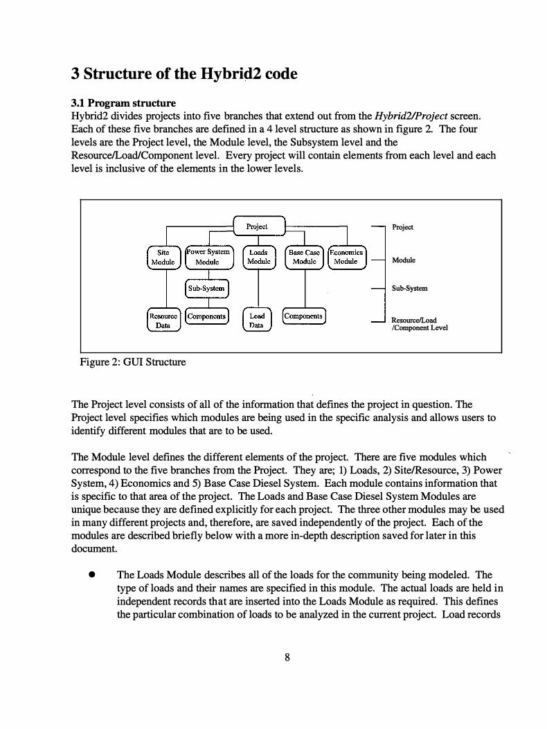
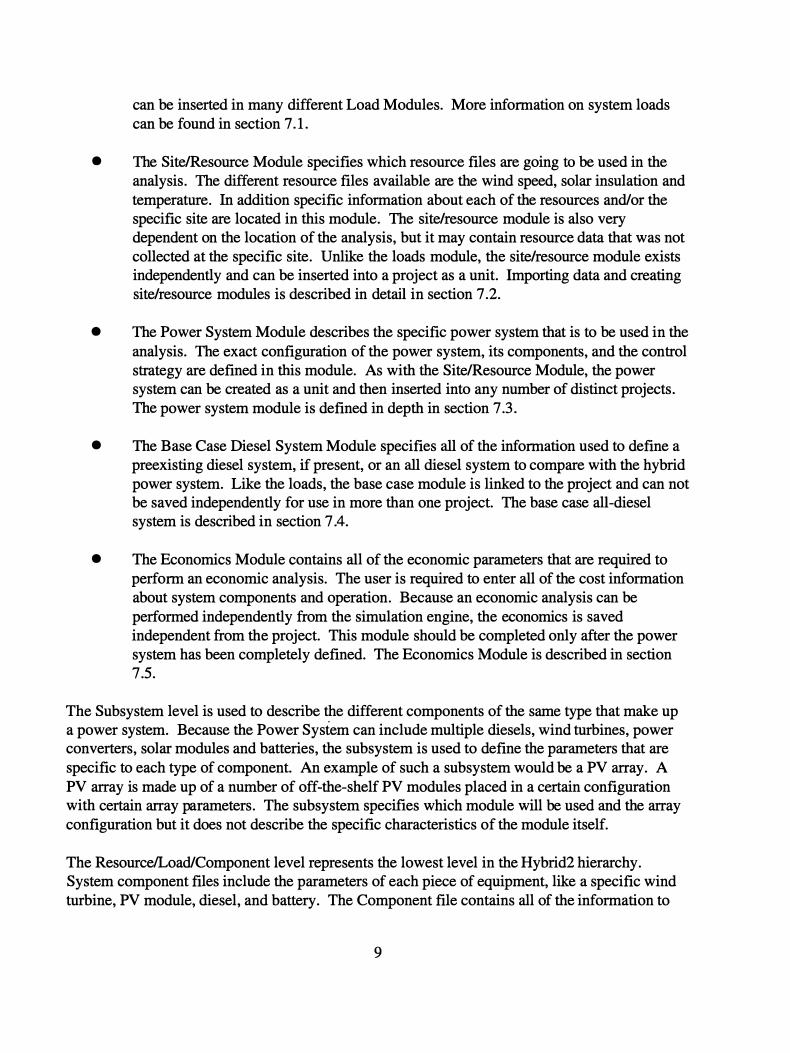
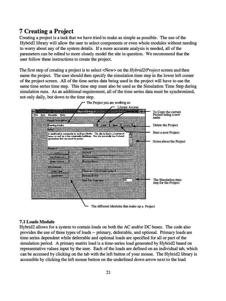
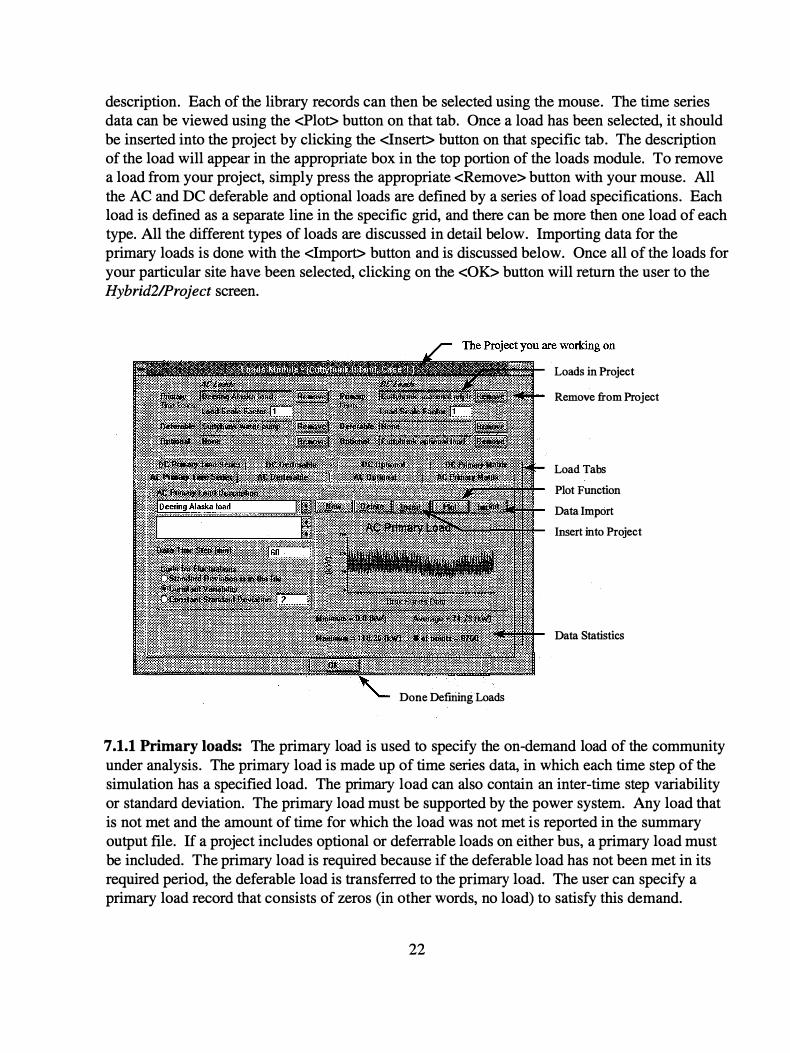
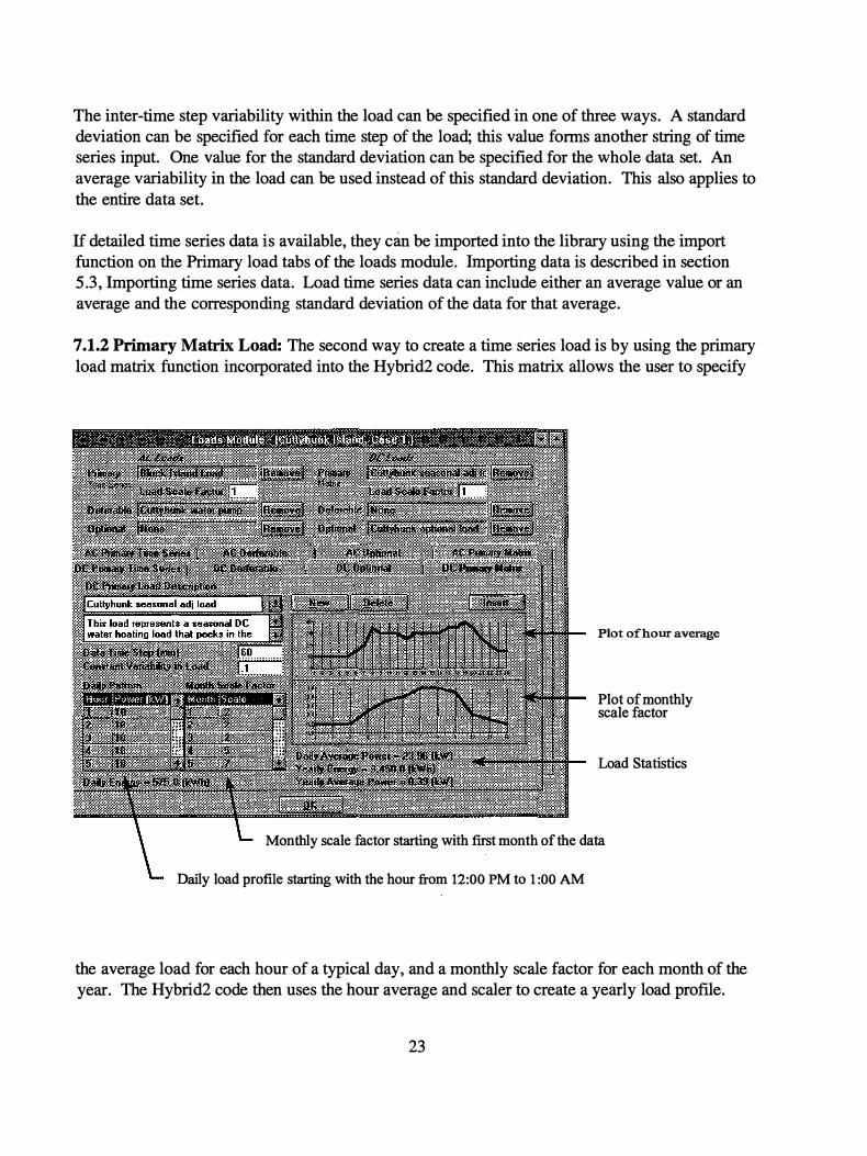
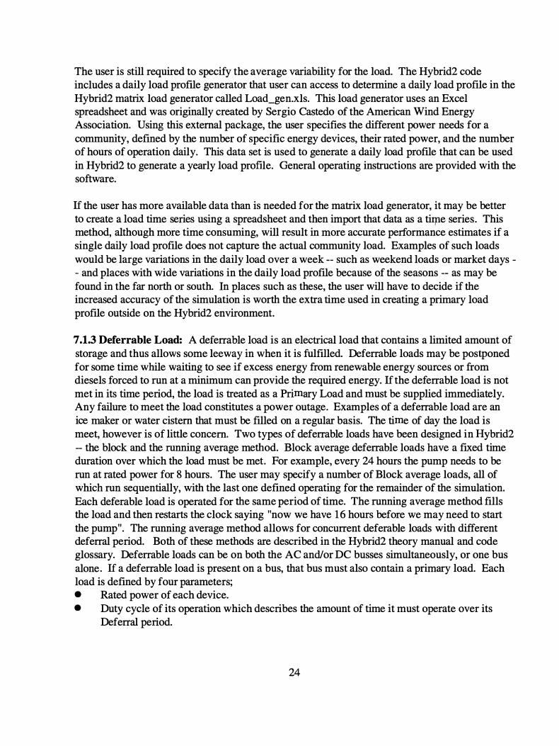
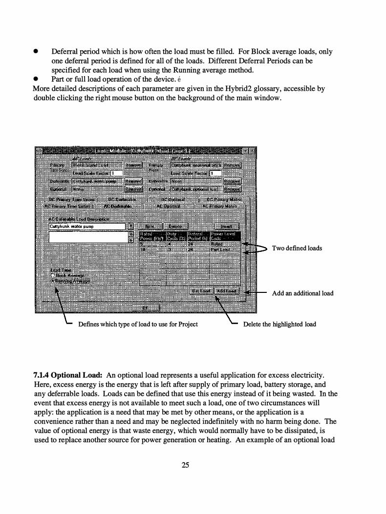
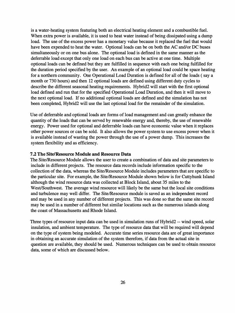
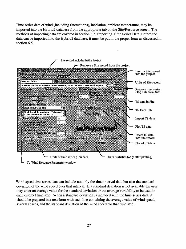
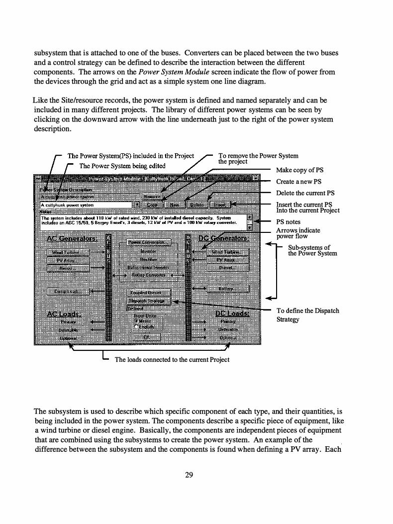
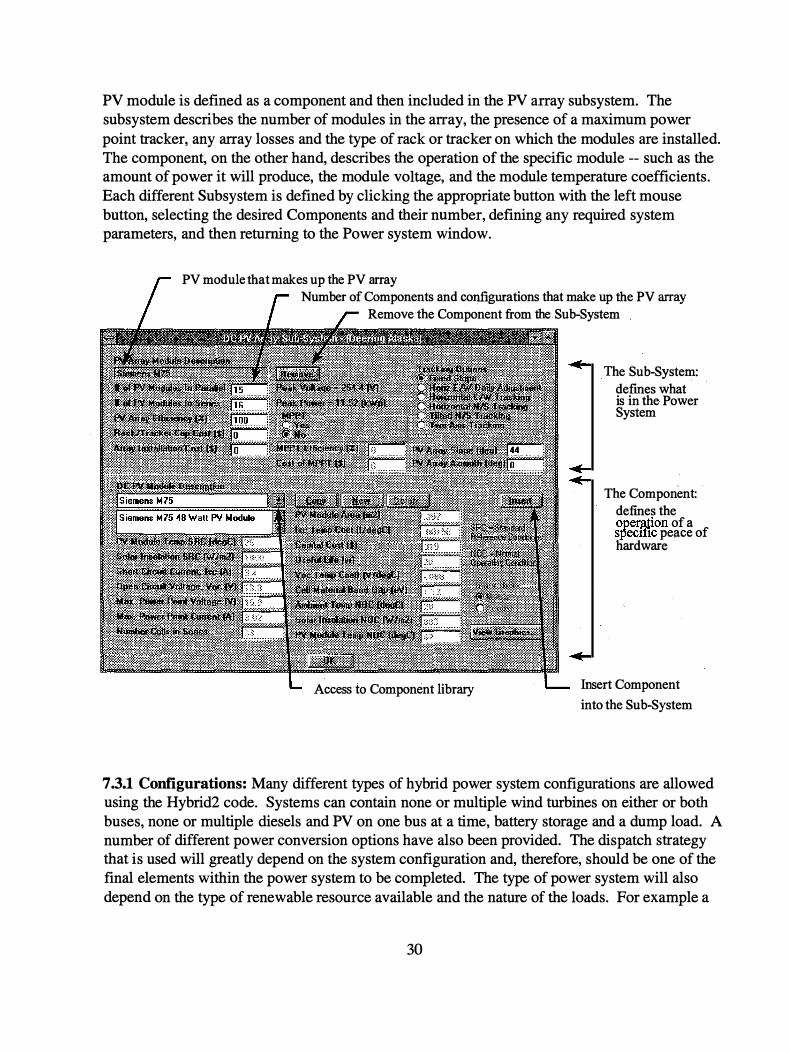
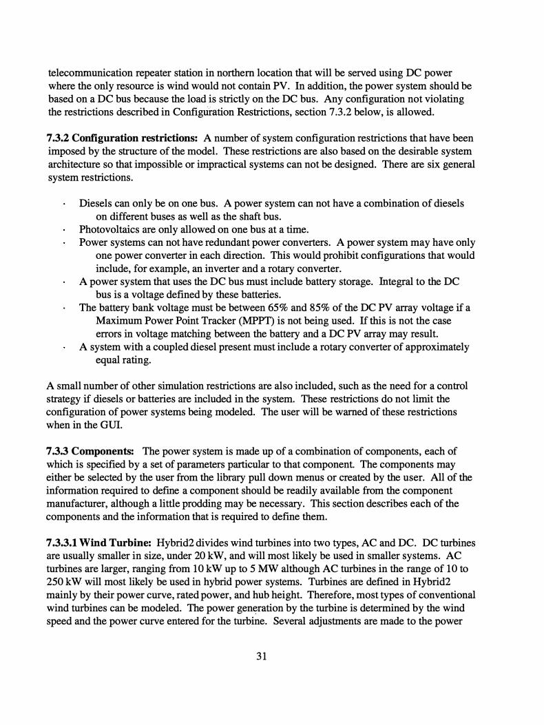
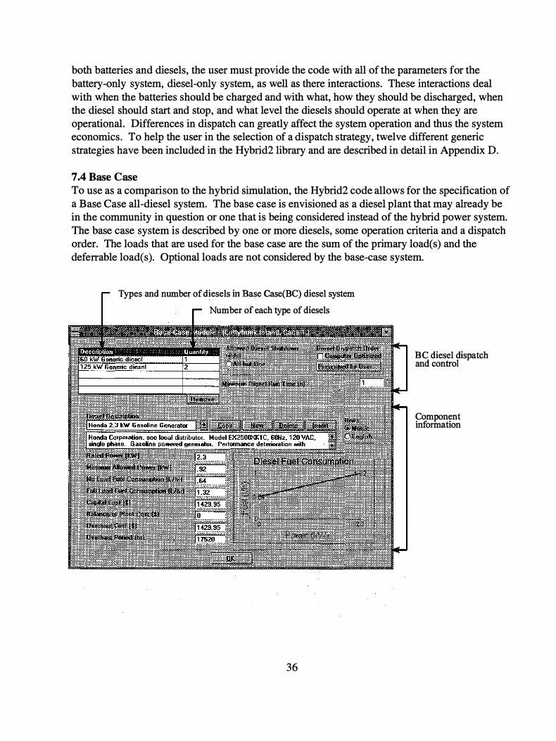
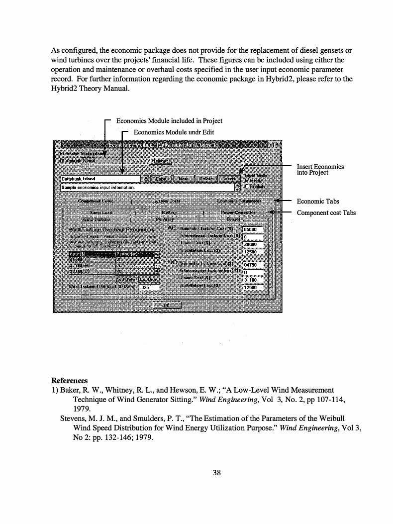
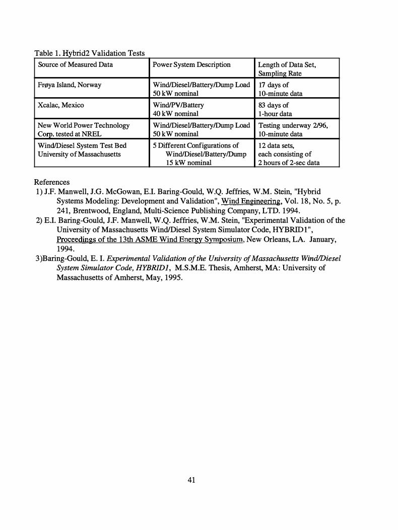
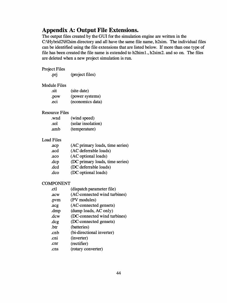
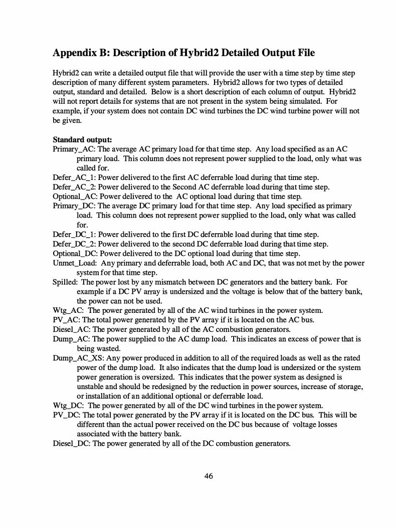
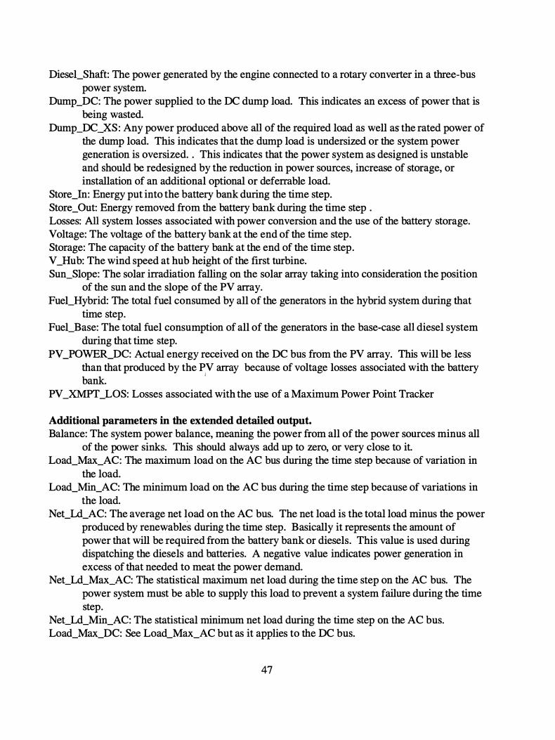
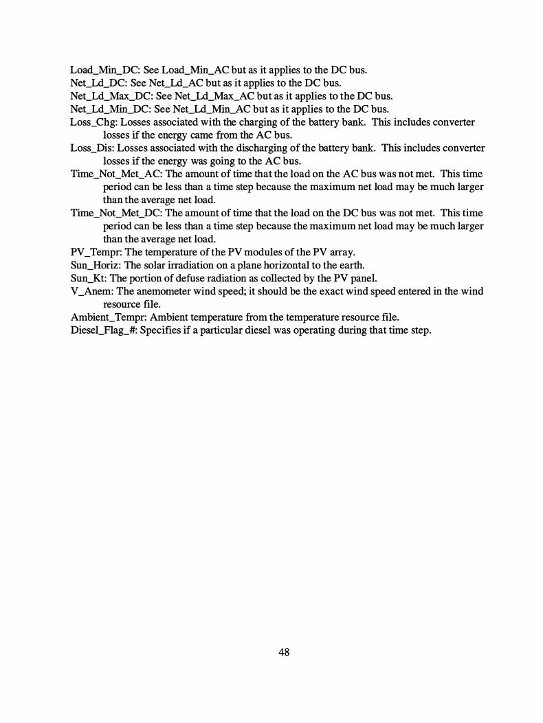
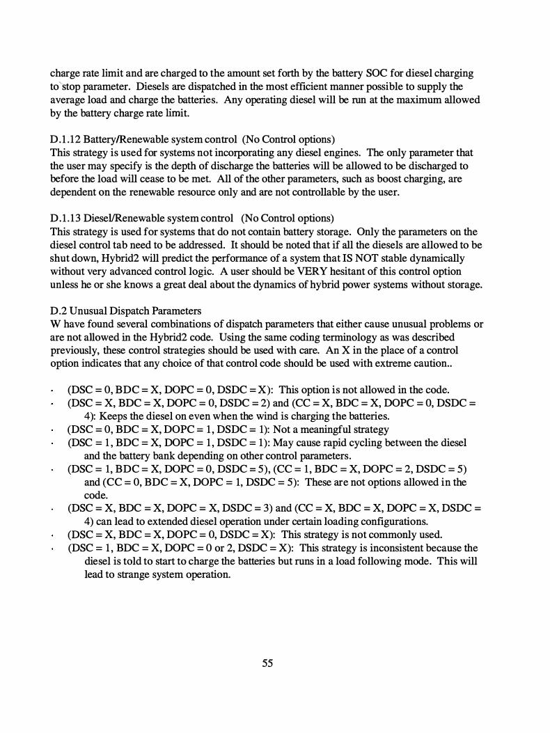
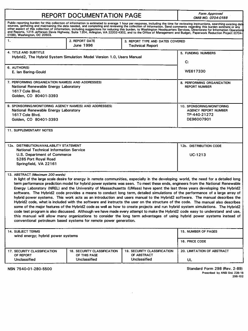


![05 Hybrid2 Handout[1]](https://img.pdfslide.us/doc/110x75/577d21021a28ab4e1e944277/05-hybrid2-handout1.jpg)