Embed Size (px)
Citation preview

Hybrid Wood and Steel Sole Plate Connection Walls to Floors Testing Report
R E S E A R C H R E P O R T R P 0 3 - 4 2 0 0 3 R E V I S I O N 2 0 0 6
American Iron and Steel Institute
rese
arch
repo
rt

Hybrid Wood and Steel Sole Plate Connection Walls to Floors Testing Report i
DISCLAIMER
The material contained herein has been developed by researchers based on their research findings and is for general information only. The information in it should not be used without first securing competent advice with respect to its suitability for any given application. The publication of the information is not intended as a representation or warranty on the part of the American Iron and Steel Institute, Steel Framing Alliance, or of any other person named herein, that the information is suitable for any general or particular use or of freedom from infringement of any patent or patents. Anyone making use of the information assumes all liability arising from such use.
Copyright 2003 American Iron and Steel Institute / Steel Framing Alliance Revised Edition Copyright 2006 American Iron and Steel Institute / Steel Framing Alliance

ii Hybrid Wood and Steel Sole Plate Connection Walls to Floors Testing Report
PREFACE
This report was developed by the NAHB Research Center for the Steel Framing Alliance and the U.S. Department of Housing and Urban Development as part of a project on wood-to-steel hybrid connections. The objectives of this project were to compile, develop and test connection details illustrating recommended methods of joining cold-formed steel framing with wood framing to aid in the integration of wood and steel framing and, thereby, expand the use of steel in the residential market.
This portion of the project involved a series of tests to evaluate the capacity of 7 different wood-to-steel and 6 different steel-to-wood sole plate configurations. The findings were incorporated in the Hybrid Wood and Steel Details – Builder’s Guide and provided a basis for the AISI Committee on Framing Standards to allow the attachment of steel walls to the sub-floor sheathing without direct connection to floor joists in the AISI Standard for Cold-Formed Steel Framing - Prescriptive Method for One and Two Family Dwellings.
Research Team Steel Framing Alliance

Hybrid Wood and SteelSole Plate Connection
Walls to Floors Testing Report
Prepared for
The U.S. Department of Housing and Urban DevelopmentOffice of Policy Development and Research Washington, DC
and
Steel Framing Alliance (SFA) Washington, DC
by
NAHB Research Center, Inc. 400 Prince George's Boulevard Upper Marlboro, MD 20774-8731
February 2003

Hybrid Wood and Steel, Sole Plate Connection – Walls to Floors Testing Report
ii
Disclaimer
While the information in this document is believed to be accurate, neither the authors, nor
reviewers, nor the U.S. Department of Housing and Urban Development, nor the Steel Framing
Alliance, nor the NAHB Research Center, Inc., nor any of their employees or representatives
make any warranty, guarantee, or representation, expressed or implied, with respect to the
accuracy, effectiveness, or usefulness of any information, method, or material in this document,
nor assumes any liability for the use of any information, methods, or materials disclosed herein,
or for damages arising from such use.
Notice
The contents of this report are the views of the contractor and do not necessarily reflect the views or policies of the
U.S. Department of Housing and Urban Development or the U.S. Government. The U.S. Government does not
endorse producers or manufacturers. Trade and manufacturers’ names appear herein solely because they are
considered essential to the contents of this report.

Hybrid Wood and Steel, Sole Plate Connection – Walls to Floors Testing Report
iii
Acknowledgements
This report was prepared for the U.S. Department of Housing and Urban Development (HUD)
and the Steel Framing Alliance (SFA). Special appreciation is extended to Bill Freeborne of
HUD and Kevin Bielat of the American Iron and Steel Institute (AISI) for their guidance and
assistance throughout the project. The NAHB Research Center staff involved in this project are:
Project Manager Jay P. Jones, PE
Technical Reviewer(s) Vladimir Kochkin
Nader R. Elhajj, PE
Lab Technician(s) Stuart Denniston
Administrative Support Lynda Marchman
The Research Center gratefully acknowledges the assistance of Joseph Marino of Dale/Incor for
providing the steel used in the testing phase of this project.

Hybrid Wood and Steel, Sole Plate Connection – Walls to Floors Testing Report
iv

Hybrid Wood and Steel, Sole Plate Connection – Walls to Floors Testing Report
Forward
The NAHB Research Center, U.S. Department of Housing and Urban Development (HUD) and
the Steel Framing Alliance have worked cooperatively to introduce cold-formed steel framing
into the residential construction market and to provide objective builders and homeowners with a
cost-effective alternative construction material. To accomplish this objective, many barriers have
been overcome. However, one of the remaining barriers is the lack of hybrid construction details
giving builders the option of using steel or wood where it makes the most sense.
In response, HUD and the Steel Framing Alliance commissioned the NAHB Research Center to
review existing details and develop a comprehensive list of hybrid wood and steel connection
details. Details lacking engineering data required testing. One such detail was the hybrid wall-to-
floor connection detail. This report is a summary of the testing procedures and results used to
develop the hybrid wall-to-floor connection detail.
Alberto Faustino Trevino
Assistant secretary for
Policy Development and Research

Hybrid Wood and Steel, Sole Plate Connection – Walls to Floors Testing Report

Hybrid Wood and Steel, Sole Plate Connection – Walls to Floors Testing Report
vii
Executive Summary
Cold-formed steel has been widely used in commercial buildings, especially in non-load bearing
(partitions) and curtain wall applications. Cold-formed steel sections are increasingly being used
as primary structural members, such as beams, floor joists, and load-bearing walls in commercial
and residential construction.
Despite the availability of cold-formed steel framing, there are still basic barriers that impede its
adoption in the residential market. Probably one of the primary barriers is that the building
industry is generally reluctant to adopt alternative building methods and materials unless they
exhibit clear quality or performance advantages. Therefore, builders tend to use alternative
materials where it makes the most sense. Currently there is no single document that builders can
use to construct hybrid cold-formed steel and wood homes. The available information and details
for steel and wood hybrid structure are dispersed and not readily accessible to builders.
This report addresses hybrid, wall-to-floor connections, which include, the connection of wood
walls to Cold-formed steel floors, and the connection of Cold-formed steel walls to wood floors.
The testing report on hybrid, wall-to-floor connections discusses important fastener
characteristics, resistance requirements, and factors of safety. In addition, a complete test plan is
presented along with the results and recommendations.

Hybrid Wood and Steel, Sole Plate Connection – Walls to Floors Testing Report
viii

Hybrid Wood and Steel, Sole Plate Connection – Walls to Floors Testing Report
ix
Table of Contents
Page
Introduction......................................................................................................................................1
Background......................................................................................................................................2
Wall-to-Floor Connection Requirements.................................................................................... 2
Factor of Safety........................................................................................................................... 2
Fasteners ..................................................................................................................................... 3
Experimental Approach ...................................................................................................................6
Wood Framed Wall to CFS Floor....................................................................................................6
Shear Test Specimens ................................................................................................................. 6
Shear Testing Apparatus ............................................................................................................. 7
Withdrawal Test Specimens ....................................................................................................... 7
Withdrawal Testing Apparatus ................................................................................................... 8
Test Matrix.................................................................................................................................. 9
Results......................................................................................................................................... 9
Failure Modes ........................................................................................................................... 10
CFS Wall to Wood Frame Floor....................................................................................................11
Shear Test Specimens ............................................................................................................... 11
Shear Testing Apparatus ........................................................................................................... 12
Withdrawal Test Specimens ..................................................................................................... 13
Withdrawal Testing Apparatus ................................................................................................. 13
Test matrix ................................................................................................................................ 14
Results....................................................................................................................................... 15
Failure Modes ........................................................................................................................... 15
Discussion......................................................................................................................................16
Recommendations..........................................................................................................................17
Conclusion .....................................................................................................................................18
References......................................................................................................................................19

Hybrid Wood and Steel, Sole Plate Connection – Walls to Floors Testing Report
x
List of Tables
Page
Table 1 - Fasteners and Connection Types ......................................................................................5
Table 2 - Wood-to-Steel Test Matrix...............................................................................................9
Table 3 - Wood-to-Steel Test Results Summary .............................................................................9
Table 4 - Steel-to-Wood Test Matrix.............................................................................................15
Table 5 - Steel-to-Wood Test Results Summary ...........................................................................15
Table 6 - Fastener Schedule for Wood-to-Steel Connection .........................................................18
Table 7 - Fastener Schedule for Steel-to-Wood Connection .........................................................18
List of Figures
Page
Figure 1 - Hybrid Wall-to-Floor Connections .................................................................................1
Figure 2 - Loads Resisted by Sole Plate Connection.......................................................................2
Figure 3 - Tested Fasteners for Hybrid Connections .......................................................................4
Figure 4 - Shear Test Specimen for Wood-to-Steel Connections....................................................6
Figure 5 - Shear Test Specimen in UTM.........................................................................................7
Figure 6 - Withdrawal Test Specimens for Wood-to-Steel Connections ........................................8
Figure 7 - Withdrawal Test Specimen in the UTM .........................................................................8
Figure 8 - Typical Shapes of Shear Test Curves............................................................................10
Figure 9 - Typical Shapes of Withdrawal Test Curves..................................................................11
Figure 10 - Shear Test Specimen ...................................................................................................12
Figure 11 - Shear Test Specimen in UTM.....................................................................................12
Figure 12 - Withdrawal Test Specimen .........................................................................................13
Figure 13 - Withdrawal Test Specimen in UTM ...........................................................................14
Figure 14 - Displacements Measured in Withdrawal Tests ...........................................................14
Figure 15 - Fastener Locations for Steel-to-Wood Withdrawal Tests...........................................16
Figure 16 - Effect of Lateral Restraint on Shear Tests ..................................................................17
Figure 17 - Laterally Restrained and Unrestrained Test Results ...................................................17

Hybrid Wood and Steel, Sole Plate Connection – Walls to Floors Testing Report
1
Introduction
Light gauge, cold-formed steel (CFS) is becoming a popular alternative to wood framing in the
residential housing market, especially in areas where increased fire and decay resistance are
desired. In the past, homes have either been framed entirely with steel or entirely with wood, but
recently, builders have begun to integrate CFS framing with wood framing to take advantage of
certain desired qualities unique to each of the materials. The use of CFS and wood framing
together, referred to as hybrid construction, is a growing practice, although it is not specifically
addressed in the model codes. Therefore, since hybrid details are not readily available, builders
must rely on good judgment or designers to address certain structural details.
A common hybrid construction practice is to use wood framed walls and CFS floors, or in some
cases, CFS walls and wood framed floors. The connection of these two building components
(wall and floor) is important to the overall structural integrity of a home. Lateral resistance is
provided by the fasteners along the sole plate of the wall, and uplift resistance is typically
addressed with separate hardware. Prescriptive methods are available in model codes for wood
wall to wood floor connections, and also for steel wall to steel floor connections, but do not exist
for hybrid connections. In addition, the NDS[1][2] does not address this specific wood-steel
configuration for a theoretical solution.
The purpose of this study is to gain the information necessary to develop prescriptive methods
for connecting wood framed walls to CFS floor systems, and for connecting CFS walls to wood
framed floors (see Figure 1). Testing will be done to determine the shear and uplift capacity of
practical, hybrid, wall-to-floor connections. This study involves testing of common sized framing
components (stud walls and sheathed floor joists) connected with fasteners that are readily
available in the wood and steel trades (i.e., screws and nails).
FIGURE 1
HYBRID WALL-TO-FLOOR CONNECTIONS

Hybrid Wood and Steel, Sole Plate Connection – Walls to Floors Testing Report
2
Background
WALL-TO-FLOOR CONNECTION REQUIREMENTS
The connection between the wall and floor platform provides lateral shear resistance in
directions parallel and perpendicular to the wall (see Figure 2). The parallel connection resists
shear loads transferred from the walls, whereas the perpendicular connection resists inward and
outward wind pressure acting on the face of the wall.
FIGURE 2
LOADS RESISTED BY SOLE PLATE CONNECTION
The NDS[1][2] does not require shear values for wood screws and nails to be adjusted for
varying grain direction with respect to load directions (i.e., load parallel to grain or load
perpendicular to grain). Lateral fastener strength for any load-to-grain angle can be adequately
predicted by testing in one direction. Testing in this study was done with loading parallel to grain
to establish values for both directions.
In an engineered design, sole plate fasteners are rarely relied on for uplift resistance. Separate
brackets or straps are typically used for wind uplift connections and shear wall holddowns.
However, in conventional construction, where prescriptive methods are used, these fasteners
must contribute to the uplift resistance. Therefore, fastener withdrawal tests were also included
in this study.
FACTOR OF SAFETY
The nominal fastener design value (R) can be determined by applying an appropriate factor of
safety to average ultimate test values:.
nRR where Rn = average value of all test values
= factor of safety
The AISI [3][4] specifies a factor of safety ( ) for screwed connection as:
Uplift Lateral –
Parallel to sole
plate
Transverse –
perpendicular to
sole plate

Hybrid Wood and Steel, Sole Plate Connection – Walls to Floors Testing Report
3
61. where Resistance Factor
=QPPFM VVCVV
mmm ePFMC2222
0)(
where:
Cø = Calibration coefficient = 1.52
Mm = Mean value of the material factor = 1.10 (All connections)
Fm = Mean value of the fabrication factor = 1.00
Pm = Mean value of the professional factor for the tested
component = 1.0
0 = Target reliability index = 3.5 (connections)
VM = Coefficient of variation of the material factor = 0.10
VF = Coefficient of variation of the fabrication factor = 0.15
CP = Correction factor
= )(
)(
2
11
m
mn for 4n , and 5.7 for n = 3
n = Number of tests
VP = Coefficient of variation of the test results (from test results)
m = Degree of freedom = n – 1
VQ = Coefficient of variation of the load effect = 0.21
A factor of safety, based on the number of tests and corresponding coefficient of variation, was
calculated for each shear test set (see Appendix B). The average factor of safety for all shear test
sets was approximately 3.6. The recommended design shear values presented in this report are
based on a factor of safety of 3.6 applied to average ultimate loads. The proposed design values
for withdrawal in this report are based on one fifth of the average ultimate test values, which is
consistent with nail withdrawal design values used in wood construction [2].
FASTENERS
Fasteners used for hybrid connections must have qualities that will; (1) prevent head pull
through, (2) limit gaps between connected materials, (3) provide thread grip, and (4) easily
penetrate the materials. Characteristics, such as head type, length, and point style, will vary
depending on the type and thickness of the substrate. Several fastener types were included in this
connection study (see Figure 3). The tested fasteners were selected based on product availability
and suitability for the application. Seven different screw types and one nail type were tested.

Hybrid Wood and Steel, Sole Plate Connection – Walls to Floors Testing Report
4
FASTENERS
Ref # 1 .131” x 3.25” pneumatic nail (un-coated) Ref # 5 #8 x 3” self-drilling, bugle head
Ref # 2 #8 x 3” self-tapping, flat headRef # 6 #8 x 1.5” self-piercing, wafer head
(fully threaded)
Ref # 3 #10 x 3” self-tapping, flat headRef # 7 #8 x 1-5/8” self- drilling, wafer head
(fully threaded)
Ref # 4 #8 x3” self-piercing, wafer head
(partially threaded)
Ref # 8 #10 x 2.5” self-drilling, pan head
(fully threaded)
FIGURE 3
TESTED FASTENERS FOR HYBRID CONNECTIONS
The fastener types for the various hybrid configurations were chosen based on their ability to
penetrate through the materials, and effectiveness once installed. Countersinking heads were
used when wood was attached to steel, and low profile heads were used when steel was attached
to wood. Self-drilling points were used when wood was attached to steel, and self-piercing points
(sharp points) were used when 33 mil steel was attached to wood, although self-drilling points
were needed when thicker steel was used. The following section describes screw characteristics,
and Table 1 lists the fasteners that were used in the various hybrid configurations.
Screw Point Types
Self-tapping point – Used for the wood-to-wood connections only (i.e., wood sole plate to
OSB). This type of point cannot be used in the steel connections without a pre-drilled
hole. (See Figure 3, fastener reference numbers: 2 and 6.)
Self-drilling point – Used for the wood-to-steel connections. This point is designed to
bore through the wood, and then cut through the steel. The threads engage in the steel and
pull the materials (wood and steel) together. The threads are ineffective in the connected
wood member; so the head is relied on to prevent uplift. (See Figure 3, fastener reference
numbers: 5, 7 and 8.)
Self-piercing point – Used for steel track to wood floor connections when a 33 mil track
is used. The point is designed to penetrate through 33 mil steel or thinner without needing
a pre-drilled hole. (See Figure 3, fastener reference numbers: 4 and 6.)

Hybrid Wood and Steel, Sole Plate Connection – Walls to Floors Testing Report
5
Screw Head Types
Flat head – Used for the wood-to-wood connections. This head type is countersinking and
characteristic to wood screws. (See Figure 3, fastener reference numbers: 2 and 3.)
Bugle head – Used for the wood-to-steel connections. This head type is also
countersinking and similar to the flat head wood screw but has a curved transition from
the shaft to the head. This is a common head type for sharp point screws. (See Figure 3,
fastener reference number: 5.)
Wafer head – Used for the steel-to-wood connections. The head has a low profile and flat
underside. This is not a countersinking head and is suitable for steel-to-steel connections
or steel-to-wood connections. (See Figure 3, fastener reference numbers: 4, 6 and 7.)
TABLE 1
FASTENERS AND CONNECTION TYPES
CONFIGURATION NO STEEL33 MIL
(JOIST OR TRACK)
54 MIL
(JOIST OR TRACK)
Nail:
0.131” x 3.25” (pneumatic) (1)
Screws:
#8 x 3” self-tapping, flat head (2)
#10 x 3” self- tapping,
flat head (3)
Nail:
0.131”x 3.25”
(pneumatic) (1)
Screws:
#8 x 3” self-drilling,
bugle head (5)
Nail:
0.131”x 3.25”
(pneumatic) (1)
Screws:
#8 x 3” self-drilling,
bugle head (5)
Nail:
0.131”x 3.25”
(pneumatic) (1)
Screws:
#8 x 1.5” self-piercing,
wafer head
(fully threaded) (6)
Nail:
0.131”x 3.25”
(pneumatic) (1)
Screws:
#8 x 1-5/8” self drilling,
wafer head
(fully threaded) (7)
Nail:
0.131”x 3.25”
(pneumatic) (1)
Screws:
#8 x 3” self-piercing,
wafer head
(partially threaded) (4)
Nail:
0.131”x 3.25”
(pneumatic) (1)
Screws:
#10 x 2.5” self-drilling,
pan head
(fully threaded) (8)
Note: Numbers in parenthesis (X) represent the fastener reference number as shown in Figure 3.
Wood
OSB
Wood sole
OSB
OSB
Steel track
Steel track
SteelJoist
Wood Joist
OSB

Hybrid Wood and Steel, Sole Plate Connection – Walls to Floors Testing Report
6
Experimental Approach
A series of tests were conducted to examine two types of hybrid, wall-to-floor connections: (1)
steel-to-wood and (2) wood-to-steel. The objective was to determine the lateral shear and uplift
capacity for each type of connection. Various fasteners were used in each test plan. Tests were
made with the fastener driven through the sole plate, sheathing, and into the joist, or with the
fastener driven through the sole plate and sheathing only. Each connection was tested in shear
and withdrawal. Load verses displacement relationships were plotted for each test and failure
modes were noted. A total of twenty-six different test sets were conducted. Each set consisted of
the AISI [3][4] minimum of four tests per connection.
Wood Framed Wall to CFS Floor
SHEAR TEST SPECIMENS
The specimens for the shear tests were designed to simulate the connection of a wood wall to a
CFS floor system sheathed with OSB. Each specimen consisted of a light gauge steel framed
panel. The floor joists were attached to rim track at 8-inches on center with #8 x 1/2” wafer head
screws. A 54 mil (16 gauge) and a 33 mil (20 gauge) version of the frame was tested. The frames
were sheathed on each face to accommodate the maximum number of tests per frame. The
sheathing was 23/32-inch-thick OSB and was attached to the frame with #8 x 1-5/8” bugle head,
self-drilling, reamer-tipped screws spaced 6” on center on the edges and 12-inches on center in
the field. Twelve-inch long sole plates were attached to the frame using one fastener per sole
plate. The sole plate material was 2x4-inch nominal Spruce Pine Fir (SPF) Stud-grade and had a
moisture content below 19 percent at the time of fabrication and testing. The sole plate blocks
were attached to the frame leaving two inches overhanging the side to accommodate
displacement during the tests (Figure 4). A series of tests were done with the sole plate fastener
penetrating into the steel joist, and a series was done with the sole plate fastener penetrating into
the OSB sheathing only (missing the joist). A total of 28 sole plate specimens were attached to
each frame (14 on the top side, and 14 on the bottom side), and each sole plate was tested
individually.
FIGURE 4
SHEAR TEST SPECIMEN FOR WOOD-TO-STEEL CONNECTIONS

Hybrid Wood and Steel, Sole Plate Connection – Walls to Floors Testing Report
7
SHEAR TESTING APPARATUS
The shear specimens were tested with a 200,000 lb capacity universal test machine (UTM,
Southwark-Emery Model 78075), a Satec, Epsilon Series, 4-inch displacement gauge, and a
Newvision II Data Acquisition System. The specimens were mounted on the UTM such that the
stationary crosshead applied compression load on the protruding SPF sole plate at a constant
displacement rate of 0.10 inches per minute. This follows the displacement rate used in ASTM D
1761[7] for lateral shear testing of fasteners in wood. The bottom of the frame was securely
attached to the UTM table with bar clamps. The sole plate specimens were oriented in a parallel
to grain loading direction. A 1000 lb capacity load cell was mounted between the cross head and
the plate to measure the compression load. A 4-inch displacement gauge was mounted on the
sheathing to measure relative movement between the sole plate and the sheathing (see Figure 5).
FIGURE 5
SHEAR TEST SPECIMEN IN UTM
WITHDRAWAL TEST SPECIMENS
The specimens for the withdrawal tests were “T” sections formed from 6-inch wide strips of
23/32-inch-thick OSB attached to light gauge steel joists. Specimens were also made without the
steel joist (Figure 6). The specimens were 48 inches long and were fastened together with #8 x 1-
5/8” bugle head, self-drilling, reamer-tipped screws spaced 6-inches on center. The test fasteners
were driven through a sacrificial sole plate and into the specimen. Prior to testing, the sole plate
was removed without disturbing the fastener, which was left protruding 1.5 inches out of the
specimen. Test fasteners were installed at three inches on center along the “T” section to allow
multiple tests per specimen.
1000 lb Load Cell
UTM Stationary crosshead
4”Displacement
Gauge
Sole plate samples
Tested fastener
Table

Hybrid Wood and Steel, Sole Plate Connection – Walls to Floors Testing Report
8
FIGURE 6
WITHDRAWAL TEST SPECIMENS FOR WOOD-TO-STEEL CONNECTIONS
WITHDRAWAL TESTING APPARATUS
The withdrawal specimens were mounted in a “C” shaped support attached to the one head of the
UTM. Tension load was applied at a constant displacement rate of 0.10 inches per minute. The
opposite head of the UTM was equipped with a nail claw, which was allowed to rotate about one
axis and securely grip the fastener head. A 1000 lb capacity load cell was mounted on the
underside of the upper crosshead to measure the withdrawal load. A Satec, Epsilon-series, 1-inch
displacement gauge was mounted on the stationary head to measure withdrawal movement of the
nail relative to the surface of the adjacent OSB sheathing (see Figure 7).
FIGURE 7
WITHDRAWAL TEST SPECIMEN IN THE UTM
“C”Support
UTM Stationary crosshead
Specimen
1-inch Displacement
Gauge
Displacement gauge measured change in this dimension.

Hybrid Wood and Steel, Sole Plate Connection – Walls to Floors Testing Report
9
TEST MATRIX
Seven shear and seven withdrawal test sets were completed. Each set had a variation in the
fastener type and substrate, and consisted of a minimum of four tests. A total of 28 individual
shear tests and 50 individual withdrawal tests were done. The matrix in Table 2 shows the
fasteners, materials, and number of tests conducted for each set.
TABLE 2
WOOD –TO - STEEL TEST MATRIX
NUMBER OF REPETITIONS
Shear Withdrawal
FASTENERR
ef.
Nu
mb
er
OSB
only
OSB and
20 ga
OSB and
16 ga
OSB
only
OSB and
20 ga
OSB and
16 ga
0.131-inch x 3 1/4-inch pneumatic nail 1 4 4 6 10 5 5
#8 x 3-in self-tapping, flat head screw 2 4 10
#10 x 3-in self-tapping, flat head
screw3 4 10
#8 x 3-in self-drilling, bugle head
screw5 4 4 5 5
RESULTS
Table 3 is a summary of the wood wall to steel floor test results. For individual test results see
Appendix A.
TABLE 3
WOOD-TO-STEEL TEST RESULTS SUMMARY
SHEAR TEST RESULTS
Test Set Fastener Ref # Substrate # Tests Avg. Ult. Std. Dev. COV
1 0.131” x 3.25” Nail 1 OSB 4 332.1 lbs 73.8 lbs 0.22
2 # 8 x 3” Screw (ST, FH) 2 OSB 4 413.0 lbs 43.6 lbs 0.11
3 #10 x 3” Screw (ST, FH) 3 OSB 4 623.1 lbs 84.1 lbs 0.13
4 0.131” x 3.25” Nail 1 OSB – 20ga 4 387.6 lbs 25.7 lbs 0.07
5 # 8 x 3” Screw (SD, BH) 5 OSB – 20ga 4 385.1 lbs 87.9 lbs 0.23
6 0.131” x 3.25” Nail 1 OSB – 16ga 6 454.8 lbs 62.5 lbs 0.14
7 # 8 x 3” Screw (SD, BH) 5 OSB – 16ga 4 459.7 lbs 48.0 lbs 0.10
WITHDRAWAL TEST RESULTS
Test Set Fastener Ref # Substrate # Tests Avg. Ult. Std. Dev. COV
8 0.131” x 3.25” Nail 1 OSB 10 119.2 lbs 43.5 lbs 0.36
9 # 8 x 3” Screw (ST, FH) 2 OSB 10 296.6 lbs 65.8 lbs 0.22
10 #10 x 3” Screw (ST, FH) 3 OSB 10 304.6 lbs 60.8 lbs 0.20
11 0.131” x 3.25” Nail 1 OSB – 20ga 5 211.0 lbs 18.7 lbs 0.09
12 # 8 x 3” Screw (SD, BH) 5 OSB – 20ga 5 527.8 lbs 74.6 lbs 0.14
13 0.131” x 3.25” Nail 1 OSB – 16ga 5 323.8 lbs 36.9 lbs 0.11
14 # 8 x 3” Screw (SD, BH) 5 OSB – 16ga 5 1031.8 lbs 65.7 lbs 0.06
ST = Self-tapping, SD = Self-drilling, FH = Flat head, BH = Bugle head
For SI : 1 inch = 25.4 mm, 1 lb = 4.448 N

Hybrid Wood and Steel, Sole Plate Connection – Walls to Floors Testing Report
10
FAILURE MODES
Different failure modes were observed in the various shear test sets, but were consistent within
each set. The nailed connections exhibited nail yielding at ultimate load, but continued to support
near-ultimate loads through large sole plate displacements. The screwed connections exhibited a
less ductile failure, with loads dropping off abruptly after the ultimate load was achieved. The
ultimate load corresponded with the breakage of the screw (see Figure 8).
������������������������������������������������
������������
�����������������������������������������������������������������������������������������������������������������������������������������������������������������������������������������������������������������������������������������������������������������������������������������������������
�����������������������������������������������������������������������������������������������������������������������������������������������������������������������������������������������������������������������������������������������������������������������������������������������������������������������������������������������������������������������������������������������������������������������������������������������������������������������������������������������������������������������������������������������������������������������������������������������������������������������������������������������������������
������������������������������������
�����������������������������������������������������������������������������������������������������������������������������������������������������������������������������������������������������������������������������������������������������������������������������������������������������������������������������������������������������������������������������������������������������������������������������������������������������������������������������������������������������������������������������������������������������������������������������������������������������������������������������������������������������������������������������������������������������������������������������������������������������������������������������������������������������������������������������������������������������������������������������������������������������������������������������������������������������������������������������������������������������������������������������������������������������������������������������������������������������������������������������������������������������������������������������������������������������������������������������������������������������������������������������������������������������������������������������������������������������������������������������������������������������������������������������������������������������������������������������������������������������������������������������������������������������������������������������������������������������������������������������������������������������������������������������������������������������������������������������������������������������������������������������������������������������������������������������������������������������������
��������������������������������������������������������������������������������������������������������������������������������������������������������������������������������������������������������������������������������������������������������������������������������������������������������������������������������������������������������������������������������������������������������������������������������������������������������������������������������������������������������������������������������������������������������������������������������������������������������������������������������������������������������������������������������������������������������������������������������������
��������������������������������������������������������������������������������������������������������������������������������������������������������������������������������������������������������������������������������������������������������������������������������������������������������������������������������������������������������������������������������������������������������
�����������������������������������������������������������������������������������������
��������������������������������������
0
100
200
300
400
500
600
0.00 0.20 0.40 0.60 0.80 1.00 1.20
Displacement (in)
Lo
ad
(lb
s)
#8 Screw������������������
Nail
FIGURE 8
TYPICAL SHAPES OF SHEAR TEST CURVES
The mode of failure for all withdrawal tests was fastener pullout. Fastener yielding or failure was
not observed. The load verses displacement curves had consistent patterns within test sets. The
screwed connections typically reached an ultimate capacity, and then began to pull out of the
substrate. As the screw pulled out, the threads became less effective and the resistance reduced.
The nailed connections generally reached an ultimate capacity, and then began to pull out with a
fairly constant resistance, which was slightly below the ultimate level (see Figure 9). These load-
displacement patterns were consistent for all withdrawal tests. Note the load delay in the nail
curve. This was likely caused by the gradual engagement of the claw grip on the nail head.
Screw breakage
For SI: 1 inch = 25.4 mm, 1lb = 4.448 N

Hybrid Wood and Steel, Sole Plate Connection – Walls to Floors Testing Report
11
����������������������������������������������������������������������������������������������������������
������������������������������������������������������������������������������������������������������������
�����������������������������������������������������������������������������������������������������������������������������������������������������������������������������������������������������������������������������������������������������������������
0
50
100
150
200
0.00 0.04 0.08 0.12 0.16 0.20Displacement (in)
Lo
ad
(lb
s)
#8 Screw�����������������
Nail
FIGURE 9
TYPICAL SHAPES OF WITHDRAWAL TEST CURVES
CFS Wall to Wood Frame Floor
SHEAR TEST SPECIMENS
The specimens for the steel-to-wood shear tests were similar to the wood-to-steel test specimens.
Wood frames, matching the dimensions shown in Figure 4, were constructed using 2x6 SPF
joists. The frames were sheathed on each face with 23/32-inch-thick OSB, which was attached
with 8d common nails at 6 inches on center on the perimeter and 12 inches on center in the field.
Thirty-inch long wall track sections (33 mil and 54 mil) were attached to the frames similar to
how they were in the wood sole plate tests. Each steel track sole plate had a stiffener section
fastened to it to provide a bearing surface for the UTM, and to prevent buckling of the track (see
Figure 10). The stiffeners were attached with four #8 screws (two on each side of the track,
spaced 24 inches apart).
Resistance remained constant through pull-out
Resistance dropped off after ultimate

Hybrid Wood and Steel, Sole Plate Connection – Walls to Floors Testing Report
12
FIGURE 10
SHEAR TEST SPECIMEN
SHEAR TESTING APPARATUS
The shear testing apparatus for the steel-to-wood study was the same as the apparatus used for
the wood-to-steel study. The frames were positioned on the UTM so that the crosshead applied
compression load on the protruding stiffener. The load was applied using a constant
displacement rate of 0.10 inches per minute. A 1000 lb capacity load cell was mounted between
the cross head and the stiffener to measure the compression load, and a 4-inch displacement
gauge was mounted directly on the sheathing to measure relative movement between the sole
plate and the sheathing (see Figure 11).
FIGURE 11
SHEAR TEST SPECIMEN IN UTM
TestedFastener
Load Direction
StiffenerTrack
StiffenerAttachment
24” o.c.
Stiffener Track
OSB
4”Displacement
Gauge
1000 # Load Cell
Hybrid Wood and Steel, Sole Plate Connection – Walls to Floors Testing Report
13
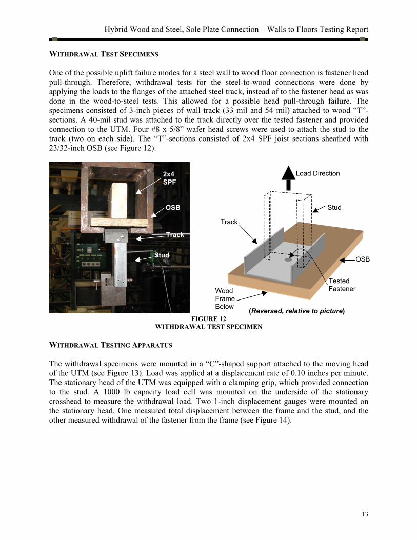
WITHDRAWAL TEST SPECIMENS
One of the possible uplift failure modes for a steel wall to wood floor connection is fastener head
pull-through. Therefore, withdrawal tests for the steel-to-wood connections were done by
applying the loads to the flanges of the attached steel track, instead of to the fastener head as was
done in the wood-to-steel tests. This allowed for a possible head pull-through failure. The
specimens consisted of 3-inch pieces of wall track (33 mil and 54 mil) attached to wood “T”-
sections. A 40-mil stud was attached to the track directly over the tested fastener and provided
connection to the UTM. Four #8 x 5/8” wafer head screws were used to attach the stud to the
track (two on each side). The “T”-sections consisted of 2x4 SPF joist sections sheathed with
23/32-inch OSB (see Figure 12).
FIGURE 12
WITHDRAWAL TEST SPECIMEN
WITHDRAWAL TESTING APPARATUS
The withdrawal specimens were mounted in a “C”-shaped support attached to the moving head
of the UTM (see Figure 13). Load was applied at a displacement rate of 0.10 inches per minute.
The stationary head of the UTM was equipped with a clamping grip, which provided connection
to the stud. A 1000 lb capacity load cell was mounted on the underside of the stationary
crosshead to measure the withdrawal load. Two 1-inch displacement gauges were mounted on
the stationary head. One measured total displacement between the frame and the stud, and the
other measured withdrawal of the fastener from the frame (see Figure 14).
TestedFastener
Track
Stud
Load Direction
Wood FrameBelow
Stud
OSB
2x4SPF
Track
OSB
(Reversed, relative to picture)

Hybrid Wood and Steel, Sole Plate Connection – Walls to Floors Testing Report
14
FIGURE 13
WITHDRAWAL TEST SPECIMEN IN UTM
FIGURE 14
DISPLACEMENTS MEASURED IN WITHDRAWAL TESTS
TEST MATRIX
Six shear, and six withdrawal test sets were completed. Each set had a variation in the fastener
type and substrate. A total of 31 shear tests and 33 withdrawal tests were conducted. The matrix
in Table 4 shows the fasteners, materials, and minimum numbers of tests run for each set. There
was a minimum of 4 tests per set. Following AISI[3][4], additional tests were conducted (up to 6
per set) if any one test varied 15 percent from the average test value for that set.
Displacement Gauges
Measures total displacement
Measures fastener withdrawal
Extension attached near fastener head
“C” Support
Grip

Hybrid Wood and Steel, Sole Plate Connection – Walls to Floors Testing Report
15
TABLE 4
STEEL TO WOOD TEST MATRIX
RESULTS
Table 5 is a summary of the steel wall to wood floor test results. For individual test results see
Appendix A.
TABLE 5
STEEL-TO-WOOD TEST RESULTS SUMMARY
SHEAR TEST RESULTS
TEST SET FASTENER REF # SUBSTRATE # TESTS AVG. ULT. STD. DEV. COV
15 0.131”x 3.25” Nail 1 OSB 6 268.5 lbs 37.1 lbs 0.138
16 # 8 x 1.5” Screw (SP, WH) 6 OSB 5 412.2 lbs 88.8 lbs 0.215
17 # 8 x 1-5/8” Screw (SD, WH) 7 OSB 4 542.6 lbs 24.3 lbs 0.045
18 0.131”x 3.25” Nail 1 OSB-SPF 5 667.0 lbs 68.8 lbs 0.103
19 # 8 x 3” Screw (SP, WH) 4 OSB-SPF 4 620.0 lbs 80.3 lbs 0.129
20 #10 x 2.5” Screw (SD, PH) 8 OSB-SPF 6 1402.1 lbs 178.7 lbs 0.127
WITHDRAWAL TEST RESULTS
21 0.131”x 3.25” Nail 1 OSB 6 74.9 lbs 23.4 lbs 0.312
22 # 8 x 1.5” Screw (SP, WH) 6 OSB 6 350.2 lbs 71.6 lbs 0.204
23 # 8 x 1-5/8” Screw (SD, WH) 7 OSB 4 331.0 lbs 35. 0 lbs 0.106
24 0.131”x 3.25” Nail 1 OSB-SPF 6 402.0 lbs 48.8 lbs 0.121
25 # 8 x 3” Screw (SP, WH) 4 OSB-SPF 7 *630.5 lbs 127.2 lbs 0.202
26 #10 x 2.5” Screw (SD, PH) 8 OSB-SPF 4 1007.5 lbs 87.8 lbs 0.087
SP = Self-piercing, SD = Self drilling, WH = Wafer head, PH = Pan head
*Value is for a (2) fastener connection
For SI: 1 inch = 25.4 mm, 1lb = 4.448N
FAILURE MODES
The failure modes varied among fastener types. The nailed connections exhibited ductile failures
by sustaining near ultimate loads through large displacements. Beyond the ultimate load, the
nails typically deformed, creating a plastic hinge within the sheathing, which is characteristic to
Mode-IIIs yielding as defined in the NDS[1]. After the nail yielded, it began to withdraw from
NUMBER OF REPETITIONS
Shear Withdrawal
TRACK FASTENER
RE
F. N
UM
BE
R
OSB
only
OSB and
SPF Joist
OSB
only
OSB and
SPF Joist
0.131-inch x 3 1/4-inch pneumatic nail 1 6 5 6 6
#8 x 1.5”, self-piercing, wafer hd (fully
threaded) 6 5 6
33 mil
#8 x 3” self-piercing, wafer hd. (part.
threaded) 4 4 7
0.131-inch x 3 1/4-inch pneumatic nail 1
#8 x 1-5/8” self-drill., wafer hd. (fully
threaded) 7 4 4
54 mil
#10 x 2.5” self-drill., pan head (fully
threaded) 8 6 4

Hybrid Wood and Steel, Sole Plate Connection – Walls to Floors Testing Report
16
the substrate. In contrast, the screwed connections broke in an abrupt manner. The break was
consistently near the head of the screw at the steel-wood interface.
The withdrawal failure modes varied by fastener and substrate type. In tests where the fastener
was driven into the sheathing only, fastener pullout was observed at relatively low load levels.
When the fastener was driven into the sheathing and joist, either the head of the fastener broke
off, or large bending deformations in the track and stud occurred before the fastener pulled out of
the substrate. Tests, which exhibited large specimen deformation prior to fastener withdrawal or
failure were repeated using two fasteners (one on each edge of the track.) or with one fastener
toward the edge of the track and the grip shifted to align the load (see Figure 15). This prevented
the excessive track deformation prior to the connection failure. These tests ended with the
fastener head breaking off.
FIGURE 15
FASTENER LOCATIONS FOR STEEL-TO-WOOD WITHDRAWAL TESTS
Discussion
Lateral restraint of the sole plate was inherent in all shear tests. The top of the sole plate
specimen was secured to the load head by static friction, and prevented the sole plate from
shifting away from the frame as load was applied (see Figure 16). A test, which allowed for
lateral freedom of the sole plate, was performed to compare the resistance effects between an
unrestrained specimen and a restrained specimen. Rollers were placed between the load cell and
the bearing plate to allow movement in the direction of fastener withdrawal. The unrestrained
specimens in these tests reached ultimate load and then dropped resistance quickly as the sole
plate pulled away from the frame due to eccentric loading. The restrained specimen typically
maintained near ultimate resistance through large displacements. The ultimate loads were similar
in the restrained and unrestrained tests, but total displacements before failure varied significantly
(see Figure 17).
The restrained test method was used to determine fastener capacity in this study. In a building
assembly, the wall dead load and uplift hardware will prevent the sole plate from shifting away
from the frame, thus the connection is more accurately modeled by the restrained test method.
Fastenershifted to edge
Line of force Fastener at center
Line of force

Hybrid Wood and Steel, Sole Plate Connection – Walls to Floors Testing Report
17
FIGURE 16
EFFECT OF LATERAL RESTRAINT ON SHEAR TESTS
SHEAR
3.25" x 0.131"(Pneu)
OSB only
0
50
100
150
200
250
300
0.00 0.10 0.20 0.30 0.40 0.50 0.60 0.70 0.80 0.90 1.00 1.10 1.20 1.30 1.40 1.50 1.60 1.70
Displacement (in)
Lo
ad
(lb
s)
FIGURE 17
LATERALLY RESTRAINED AND UNRESTRAINED TEST RESULTS
Recommendations
Tables 6 and 7 show recommended fastener schedules for hybrid, wall-to-floor connections.
These connection schedules are based on transverse (perpendicular to the face of the wall) wind
loads only, and are applicable to walls up to 10 feet in height, for structures with an A or B
exposure defined by ASCE-7 [5]. The nominal shear resistance, based on the schedule, is also
LOAD LOAD
friction
Unrestrained Restrained
Unrestrained
Restrained
For SI: 1 inch = 25.4mm, 1lb =4.448N

Hybrid Wood and Steel, Sole Plate Connection – Walls to Floors Testing Report
18
provided. The fastener schedules, and corresponding resistances have not been increased for load
duration and should not be adjusted for duration of load in design since the substrate is a
combination of wood and steel. Adjustments for moisture content and lumber density could be
applied, but only to lower the nominal values, since the resistance contribution of the wood
(SPF) in the substrate is unknown. For varying lumber species, nominal values should be
adjusted in proportion to the lumber densities. For example, SPF (South), (S.G. = 0.36) would
require an adjustment factor of 0.36 / 0.42 = 0.86, but Southern Pine would not require an
adjustment since the density (S.G. = 0.55) is higher than that of SPF (S.G. = 0.42). Adjustments
for lumber moisture content should be made using NDS [1] Wet Service Factors (Cm).
TABLE 6
FASTENER SCHEDULE FOR WOOD-TO-STEEL CONNECTION
WOOD WALL TO STEEL FLOORUp to 110 mph
(3 Sec Gust), Exp A/B;
Max wall hgt. = 10’
Up to 140 mph
(3 Sec Gust), Exp A/B;
Max wall hgt. = 10’ Substrate Fastener
Nominal
Shear
Nominal
Withdr. Spacing5
SHEAR
RESISTANCE
PROVIDED
Spacing5
SHEAR
RESISTANCE
PROVIDED
10D Nail1 92 lbs 24 lbs (2) / 16” 138 plf (3) / 16” 207 plf
#8 Screw2 115 lbs 59 lbs (2) / 16” 172 plf (2) / 16” 172 plf OSB only
#10 Screw3 173 lbs 61 lbs (1) / 16” 129 plf (2) / 16” 259 plf
10D Nail1 107 lbs 42 lbs (2) / 16” 160 plf (2) / 16” 160 plf 20 Gauge
Floor #8 Screw4 107 lbs 106 lbs (2) / 16” 160 plf (2) / 16” 160 plf
10D Nail1 126 lbs 65 lbs (2) / 16” 189 plf (2) / 16” 189 plf 16 Gauge
Floor #8 Screw4 128 lbs 206 lbs (2) / 16” 192 plf (2) / 16” 192 plf
Fastener Specifications:
1. 0.131” x 3.25” pneumatic nail
2. #8 x 3” self tapping, flat head
3. #10 x 3” self tapping, flat head
4. #8 x 3” self drilling, bugle head
5. (2) / 16” = (2) fasteners equally spaced every 16 inches
Note: Fastener schedules are based on requirements for transverse (perpendicular to face of wall) wind
loads only. Connection requirements for uplift and shear must be verified. Requirements based on SPF
lumber, MC = 19% or less.
For SI: 1 inch = 25.4mm, 1lb = 4.448N, 1plf = 1.488 kg/m
TABLE 7
FASTENER SCHEDULE FOR STEEL-TO-WOOD CONNECTION
STEEL WALL TO WOOD FLOOR Up to 110 mph
(3 Sec Gust), Exp A/B;
Max wall hgt. = 10’
Up to 140 mph
(3 Sec Gust)ExpA/B;
Max wall hgt. = 10’ Track S u b s t r a t e Fastener Nominal
Shear
Nominal
Withdr.Spacing6
SHEAR
RESISTANCE
PROVIDEDSpacing6
SHEAR
RESISTANCE
PROVIDED
10D Nail1 74 lbs 15 lbs (3) / 24” 111 plf (5) / 24” 185 plf OSB
#8 Screw2 137 lbs 70 lbs (2) / 24” 137 plf (3) / 24” 205 plf
10D Nail1 185 lbs 80 lbs (2) / 24” 185 plf (2) / 24” 185 plf 20 ga
OSB – 2x6
SPF #8 Screw3 172 lbs 63 lbs (2) / 24” 172 plf (2) / 24” 172 plf
OSB #8 Screw4 151 lbs 66 lbs (2) / 24” 151 plf (3) / 24” 226 plf
16 ga OSB – 2x6
SPF#10 Screw5 389 lbs 202 lbs (1) / 24” 194 plf (2) / 24” 389 plf
Fastener Specifications:
1. 0.131” x 3.25” pneumatic nail
2. #8 x 1.5” self piercing, wafer head (fully threaded)
3. #8 x 3” self piercing, wafer head (partially threaded)
4. #8 x 1-5/8” self drilling, wafer head (fully threaded)
5. #10 x 2.5” self drilling, pan head (fully threaded)
6. (2) / 24” = (2) fasteners every 24 inches
Note: Fastener schedules are based on requirements for transverse (perpendicular to face of wall) wind
loads only. Connection requirements for uplift and shear must be verified.
Requirements based on SPF lumber, MC = 19% or less.
For SI: 1 inch = 25.4mm, 1lb = 4.448N, 1plf = 1.488 kg/m
Conclusion
The fastening schedules presented in this report provide practical solutions for hybrid, wall-to-
floor connections. The fasteners were chosen to accommodate specific building materials readily
available in the home building market. High cost, specialty fasteners were avoided. Substitute
fasteners, with equal or higher design values, can be used, but proper fastener characteristics,
such as head type, point style, and threading, must be suitable for the intended use.

Hybrid Wood and Steel, Sole Plate Connection – Walls to Floors Testing Report
19
The fastening schedules recommended in this report are for resistance to transverse
(perpendicular to the face of the wall) wind loads only. These schedules should not be relied
upon for shear and uplift resistance that may be required for whole-building lateral design, unless
they are specifically checked using the allowable capacities provided.
Some of the tests done in this study involved fastening the sole plate to the OSB sheathing only.
The purpose of this was to investigate the effectiveness of this connection and determine if it
would be an acceptable fastening option. If so, it would allow framers to quickly and easily
install walls without having to be concerned with accurate fastener placement. It would also
allow inspectors to easily verify proper attachment by counting fastener heads on the sole plate.
The connection schedules for the OSB-only and the OSB-joist are similar. Generally, only one or
two additional fasteners are required per sixteen or twenty-four inches when fasteners are
installed into the OSB only. Therefore, the sole plate to sheathing only connection is a viable,
efficient, and economical connection option. Uplift values are lower in the OSB-only
connections, but this could be addressed with additional fasteners or separate hold-downs if
required. Adding additional fasteners to allow for this type of connection is a cost effective
alternative, since the speed of wall installation could be increased without compromising the
needed capacity.
References
[1] National Design Specification for Wood Construction (NDS), 1997 Edition, American Forest
and Paper Association, American Wood Council, Washington, DC, June 1997.
[2] National Design Specification for Wood Construction Commentary, 1997 Edition, American
Forest and Paper Association, American Wood Council, Washington, DC, June 1997.
[3] North American Specification for the Design of Cold-Formed Steel Structural Members,
2001 Edition, American Iron and Steel Institute (AISI), Washington, DC, June 2002.
[4] Commentary on North American Specification for the Design of Cold-Formed Steel Structural Members, 2001 Edition, American Iron and Steel Institute (AISI), Washington,
DC, June 2002.
[5] Structural Design Loads for One- and Two- Family Dwellings, U.S. Department of Housing
and Urban Development, Office of Policy Development and Research, Washington, DC,
May 2001.
[6] Minimum Design Loads for Buildings and Other Structures (ASCE 7-98), American Society
of Civil Engineers, Reston, VA, January 2000.
[7] ASTM D1761- 88 (Reapproved 1995) Standard Test Methods for Mechanical Fasteners in
Wood, American Society for Testing and Materials (ASTM), West Conshohocken, PA. 1995.

Hybrid Wood and Steel, Sole Plate Connection – Walls to Floors Testing Report
20

Hybrid Wood and Steel, Sole Plate Connection – Walls to Floors Testing Report
Appendix A

Hybrid Wood and Steel, Sole Plate Connection – Walls to Floors Testing Report
Hybrid Wood and Steel, Sole Plate Connection – Walls to Floors Testing Report
A-1
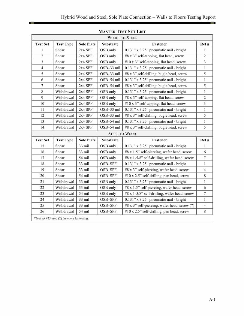
MASTER TEST SET LIST
WOOD –TO-STEEL
Test Set Test Type Sole Plate Substrate Fastener Ref #
1 Shear 2x4 SPF OSB only 0.131” x 3.25” pneumatic nail - bright 1
2 Shear 2x4 SPF OSB only #8 x 3” self-tapping, flat head, screw 2
3 Shear 2x4 SPF OSB only #10 x 3” self-tapping, flat head, screw 3
4 Shear 2x4 SPF OSB–33 mil 0.131” x 3.25” pneumatic nail - bright 1
5 Shear 2x4 SPF OSB–33 mil #8 x 3” self-drilling, bugle head, screw 5
6 Shear 2x4 SPF OSB–54 mil 0.131” x 3.25” pneumatic nail - bright 1
7 Shear 2x4 SPF OSB–54 mil #8 x 3” self-drilling, bugle head, screw 5
8 Withdrawal 2x4 SPF OSB only 0.131” x 3.25” pneumatic nail - bright 1
9 Withdrawal 2x4 SPF OSB only #8 x 3” self-tapping, flat head, screw 2
10 Withdrawal 2x4 SPF OSB only #10 x 3” self-tapping, flat head, screw 3
11 Withdrawal 2x4 SPF OSB–33 mil 0.131” x 3.25” pneumatic nail - bright 1
12 Withdrawal 2x4 SPF OSB–33 mil #8 x 3” self-drilling, bugle head, screw 5
13 Withdrawal 2x4 SPF OSB–54 mil 0.131” x 3.25” pneumatic nail - bright 1
14 Withdrawal 2x4 SPF OSB–54 mil #8 x 3” self-drilling, bugle head, screw 5
STEEL-TO-WOOD
Test Set Test Type Sole Plate Substrate Fastener Ref #
15 Shear 33 mil OSB only 0.131” x 3.25” pneumatic nail - bright 1
16 Shear 33 mil OSB only #8 x 1.5” self-piercing, wafer head, screw 6
17 Shear 54 mil OSB only #8 x 1-5/8” self-drilling, wafer head, screw 7
18 Shear 33 mil OSB–SPF 0.131” x 3.25” pneumatic nail - bright 1
19 Shear 33 mil OSB–SPF #8 x 3” self-piercing, wafer head, screw 4
20 Shear 54 mil OSB–SPF #10 x 2.5” self-drilling, pan head, screw 8
21 Withdrawal 33 mil OSB only 0.131” x 3.25” pneumatic nail - bright 1
22 Withdrawal 33 mil OSB only #8 x 1.5” self-piercing, wafer head, screw 6
23 Withdrawal 54 mil OSB only #8 x 1-5/8” self-drilling, wafer head, screw 7
24 Withdrawal 33 mil OSB–SPF 0.131” x 3.25” pneumatic nail - bright 1
25 Withdrawal 33 mil OSB–SPF #8 x 3” self-piercing, wafer head, screw (*) 4
26 Withdrawal 54 mil OSB–SPF #10 x 2.5” self-drilling, pan head, screw 8
*Test set #25 used (2) fasteners for testing.
Hybrid Wood and Steel, Sole Plate Connection – Walls to Floors Testing Report
A-2
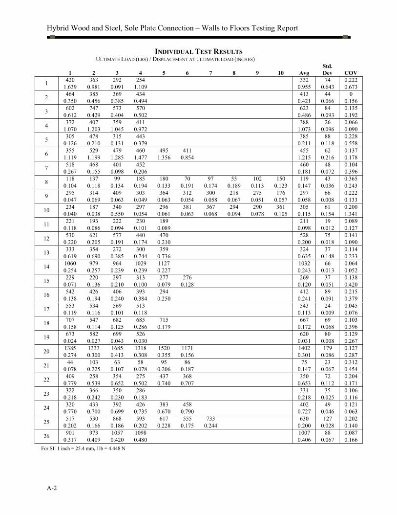
INDIVIDUAL TEST RESULTS
ULTIMATE LOAD (LBS) / DISPLACEMENT AT ULTIMATE LOAD (INCHES)
1 2 3 4 5 6 7 8 9 10 Avg
Std.
Dev COV
420 363 292 254 332 74 0.222 1
1.639 0.981 0.091 1.109 0.955 0.643 0.673
464 385 369 434 413 44 0 2
0.350 0.456 0.385 0.494 0.421 0.066 0.156
602 747 573 570 623 84 0.135 3
0.612 0.429 0.404 0.502 0.486 0.093 0.192
372 407 359 411 388 26 0.066 4
1.070 1.203 1.045 0.972 1.073 0.096 0.090
305 478 315 443 385 88 0.228 5
0.126 0.210 0.131 0.379 0.211 0.118 0.558
355 529 479 460 495 411 455 62 0.137 6
1.119 1.199 1.285 1.477 1.356 0.854 1.215 0.216 0.178
518 468 401 452 460 48 0.104 7
0.267 0.155 0.098 0.206 0.181 0.072 0.396
118 137 99 185 180 70 97 55 102 150 119 43 0.365 8
0.104 0.118 0.134 0.194 0.133 0.191 0.174 0.189 0.113 0.123 0.147 0.036 0.243
295 314 409 303 364 312 300 218 275 176 297 66 0.222 9
0.047 0.069 0.063 0.049 0.063 0.054 0.058 0.067 0.051 0.057 0.058 0.008 0.133
234 187 340 297 296 381 367 294 290 361 305 61 0.200 10
0.040 0.038 0.550 0.054 0.061 0.063 0.068 0.094 0.078 0.105 0.115 0.154 1.341
221 193 222 230 189 211 19 0.089 11
0.118 0.086 0.094 0.101 0.089 0.098 0.012 0.127
530 621 577 440 470 528 75 0.141 12
0.220 0.205 0.191 0.174 0.210 0.200 0.018 0.090
333 354 272 300 359 324 37 0.114 13
0.619 0.690 0.385 0.744 0.736 0.635 0.148 0.233
1060 979 964 1029 1127 1032 66 0.064 14
0.254 0.257 0.239 0.239 0.227 0.243 0.013 0.052
229 220 297 313 277 276 269 37 0.138 15
0.071 0.136 0.210 0.100 0.079 0.128 0.120 0.051 0.420
542 426 406 393 294 412 89 0.215 16
0.138 0.194 0.240 0.384 0.250 0.241 0.091 0.379
553 534 569 513 543 24 0.045 17
0.119 0.116 0.101 0.118 0.113 0.009 0.076
707 547 682 685 715 667 69 0.103 18
0.158 0.114 0.125 0.286 0.179 0.172 0.068 0.396
673 582 699 526 620 80 0.129 19
0.024 0.027 0.043 0.030 0.031 0.008 0.267
1385 1333 1685 1318 1520 1171 1402 179 0.127 20
0.274 0.300 0.413 0.308 0.355 0.156 0.301 0.086 0.287
44 103 63 58 95 86 75 23 0.312 21
0.078 0.225 0.107 0.078 0.206 0.187 0.147 0.067 0.454
409 258 354 275 437 368 350 72 0.204 22
0.779 0.539 0.652 0.502 0.740 0.707 0.653 0.112 0.171
322 366 350 286 331 35 0.106 23
0.218 0.242 0.230 0.183 0.218 0.025 0.116
320 433 392 426 383 458 402 49 0.121 24
0.770 0.700 0.699 0.735 0.670 0.790 0.727 0.046 0.063
517 530 868 593 617 555 733 630 127 0.202 25
0.202 0.166 0.186 0.202 0.228 0.175 0.244 0.200 0.028 0.140
901 973 1057 1098 1007 88 0.087 26
0.317 0.409 0.420 0.480 0.406 0.067 0.166
For SI: 1 inch = 25.4 mm, 1lb = 4.448 N

Hybrid Wood and Steel, Sole Plate Connection – Walls to Floors Testing Report
A-3
SHEAR TEST – LOAD DISPLACEMENT CURVES
Shear
0.131"x3.25" pneu nail
OSB only
0
50
100
150
200
250
300
350
400
450
0.0
0
0.1
0
0.2
0
0.3
0
0.4
0
0.5
0
0.6
0
0.7
0
0.8
0
0.9
0
1.0
0
1.1
0
1.2
0
1.3
0
1.4
0
1.5
0
1.6
0
1.7
0
1.8
0
1.9
0
2.0
0
Displacement (in)
Lo
ad
(lb
s)
TEST SET #1
Shear
#8 Screw
OSB only
0
50
100
150
200
250
300
350
400
450
500
0.0
0
0.0
5
0.1
0
0.1
5
0.2
0
0.2
5
0.3
0
0.3
5
0.4
0
0.4
5
0.5
0
0.5
5
0.6
0
0.6
5
0.7
0
0.7
5
0.8
0
0.8
5
0.9
0
0.9
5
1.0
0
1.0
5
Displacement (in)
Lo
ad
(lb
s)
TEST SET #2
For SI: 1 inch = 25.4mm, 1lb = 4.448N
For SI: 1 inch = 25.4mm, 1lb = 4.448N

Hybrid Wood and Steel, Sole Plate Connection – Walls to Floors Testing Report
A-4
Shear
#10 Screw
OSB only
0
100
200
300
400
500
600
700
8000
.00
0.0
5
0.1
0
0.1
5
0.2
0
0.2
5
0.3
0
0.3
5
0.4
0
0.4
5
0.5
0
0.5
5
0.6
0
0.6
5
0.7
0
0.7
5
0.8
0
0.8
5
0.9
0
0.9
5
1.0
0
1.0
5
Displacement (in)
Lo
ad
(lb
s)
TEST SET #3
Shear
0.131"x 3.25" pneu nail
OSB / 20 ga
0
50
100
150
200
250
300
350
400
450
0.0
0
0.0
5
0.1
0
0.1
5
0.2
0
0.2
5
0.3
0
0.3
5
0.4
0
0.4
5
0.5
0
0.5
5
0.6
0
0.6
5
0.7
0
0.7
5
0.8
0
0.8
5
0.9
0
0.9
5
1.0
0
1.0
5
1.1
0
1.1
5
1.2
0
1.2
5
1.3
0
1.3
5
1.4
0
1.4
5
Displacement (in)
Lo
ad
(lb
s)
TEST SET #4
For SI: 1 inch = 25.4mm, 1lb = 4.448N
For SI: 1 inch = 25.4mm, 1lb = 4.448N

Hybrid Wood and Steel, Sole Plate Connection – Walls to Floors Testing Report
A-5
Shear
0.131" x 3.25" pneu nail
OSB / 16 ga
0
100
200
300
400
500
600
0.0
0
0.1
0
0.2
0
0.3
0
0.4
0
0.5
0
0.6
0
0.7
0
0.8
0
0.9
0
1.0
0
1.1
0
1.2
0
1.3
0
1.4
0
1.5
0
1.6
0
1.7
0
1.8
0
1.9
0
2.0
0
Displacement (in)
Lo
ad
(lb
s)
TEST SET #6
Shear
#8 Screw
OSB / 20 ga
0
100
200
300
400
500
600
0.0
0
0.0
5
0.1
0
0.1
5
0.2
0
0.2
5
0.3
0
0.3
5
0.4
0
0.4
5
0.5
0
0.5
5
0.6
0
0.6
5
0.7
0
0.7
5
0.8
0
Displacement (in)
Lo
ad
(lb
s)
TEST SET #5
For SI: 1 inch = 25.4mm, 1lb = 4.448N
For SI: 1 inch = 25.4mm, 1lb = 4.448N

Hybrid Wood and Steel, Sole Plate Connection – Walls to Floors Testing Report
A-6
Shear
#8 Screw
OSB / 16 ga
0
100
200
300
400
500
6000
.00
0.0
2
0.0
4
0.0
6
0.0
8
0.1
0
0.1
2
0.1
4
0.1
6
0.1
8
0.2
0
0.2
2
0.2
4
0.2
6
0.2
8
0.3
0
0.3
2
0.3
4
0.3
6
0.3
8
Displacement (in)
Lo
ad
(lb
s)
TEST SET #7
STEEL-TO-WOOD TESTS
Shear
0.131"x3.25" pneu nail
OSB only - 20 ga track
0
50
100
150
200
250
300
350
0.0
0
0.0
5
0.1
0
0.1
5
0.2
0
0.2
5
0.3
0
0.3
5
0.4
0
0.4
5
0.5
0
0.5
5
0.6
0
0.6
5
0.7
0
0.7
5
Displacement (in)
Lo
ad
(lb
s)
TEST SET #15
For SI: 1 inch = 25.4mm, 1lb = 4.448N
For SI: 1 inch = 25.4mm, 1lb = 4.448N

Hybrid Wood and Steel, Sole Plate Connection – Walls to Floors Testing Report
A-7
Shear
#8 x 1.5" wafer / pierce
OSB - 20 ga track
0
100
200
300
400
500
600
700
800
900
10000
.00
0.0
5
0.1
0
0.1
5
0.2
0
0.2
5
0.3
0
0.3
5
0.4
0
0.4
5
0.5
0
0.5
5
0.6
0
0.6
5
0.7
0
Displacement (in)
Lo
ad
(lb
s)
TEST SET #16
Shear
#8 x 1.625 wafer head / SD
OSB - 16 ga track
0
100
200
300
400
500
600
0.0
0
0.0
2
0.0
4
0.0
6
0.0
8
0.1
0
0.1
2
0.1
4
0.1
6
0.1
8
0.2
0
0.2
2
0.2
4
0.2
6
0.2
8
0.3
0
0.3
2
0.3
4
0.3
6
0.3
8
0.4
0
0.4
2
0.4
4
Displacement (in)
Lo
ad
(lb
s)
TEST SET #17
For SI: 1 inch = 25.4mm, 1lb = 4.448N
For SI: 1 inch = 25.4mm, 1lb = 4.448N

Hybrid Wood and Steel, Sole Plate Connection – Walls to Floors Testing Report
A-8
Shear
0.131"x3.25" pneu nail
OSB Joist - 20 ga track
0
100
200
300
400
500
600
700
800
0.0
0
0.0
5
0.1
0
0.1
5
0.2
0
0.2
5
0.3
0
0.3
5
0.4
0
0.4
5
0.5
0
0.5
5
0.6
0
0.6
5
0.7
0
0.7
5
0.8
0
0.8
5
0.9
0
0.9
5
1.0
0
Displacement (in)
Lo
ad
(lb
s)
TEST SET #18
Shear
#8 x3" wafer / pierce
OSB-Joist - 20 ga track
0
100
200
300
400
500
600
700
800
0.0
0
0.0
1
0.0
1
0.0
2
0.0
2
0.0
3
0.0
3
0.0
4
0.0
4
0.0
5
0.0
5
0.0
6
0.0
6
0.0
7
0.0
7
0.0
8
0.0
8
0.0
9
0.0
9
0.1
0
Displacement (in)
Lo
ad
(lb
s)
TEST SET #19
For SI: 1 inch = 25.4mm, 1lb = 4.448N
For SI: 1 inch = 25.4mm, 1lb = 4.448N

Hybrid Wood and Steel, Sole Plate Connection – Walls to Floors Testing Report
A-9
Shear
#10 x2.5" Pan head SD
OSB-Joist - 16 ga track
0
200
400
600
800
1000
1200
1400
1600
18000
.00
0
0.0
50
0.1
00
0.1
50
0.2
00
0.2
50
0.3
00
0.3
50
0.4
00
0.4
50
0.5
00
0.5
50
Displacement (in)
Lo
ad
(lb
s)
TEST SET #20
For SI: 1 inch = 25.4mm, 1lb = 4.448N

Hybrid Wood and Steel, Sole Plate Connection – Walls to Floors Testing Report
A-10

Hybrid Wood and Steel, Sole Plate Connection – Walls to Floors Testing Report
APPENDIX B

Hybrid Wood and Steel, Sole Plate Connection – Walls to Floors Testing Report

Hybrid Wood and Steel, Sole Plate Connection – Testing Report
B-1
FACTOR OF SAFETY
= Factor of safety Resistance Factor
(Refer to text for all variables)
CALCULATED FACTOR OF SAFETY FOR SHEAR TESTS
TEST SET FASTENER # TESTS COV RES. FACT SF
1 0.131” x 3.25” pneumatic nail - bright 4 0.222 0.279 5.73
2 #8 x 3” self-tapping, flat head, screw 4 0.106 0.501 3.20
3 #10 x 3” self-tapping, flat head, screw 4 0.135 0.441 3.63
4 0.131” x 3.25” pneumatic nail - bright 4 0.066 0.575 2.78
5 #8 x 3” self-drilling, bugle head, screw 4 0.228 0.270 5.93
6 0.131” x 3.25” pneumatic nail - bright 6 0.137 0.515 3.11
7 #8 x 3” self-drilling, bugle head, screw 4 0.104 0.505 3.17
15 0.131” x 3.25” pneumatic nail - bright 6 0.138 0.514 3.11
16 #8 x 1.5” self-piercing, wafer head, screw 5 0.215 0.367 4.36
17 #8 x 1-5/8” self-drilling, wafer head, screw 4 0.045 0.606 2.64
18 0.131” x 3.25” pneumatic nail - bright 5 0.103 0.547 2.93
19 #8 x 3” self-piercing, wafer head, screw 4 0.129 0.453 3.53
20 #10 x 2.5” self-drilling, pan head, screw 6 0.127 0.529 3.02
AVG 3.63
LATERAL FORCE CALCULATIONS
Assume: Ref.
Exposure B [1]
KZ = 0.75 [1]
KD = 0.85 [1]
Lateral Pressure Coefficient for walls = 1.1 [4]
Velocity Pressure = 0.00256KD KZ V2 [5]
WIND SPEED CATEGORIES VELOCITY PRESSURE
Up to 90 mph 13 psf
Up to 110 mph 19 psf
Up to 140 mph 31 psf
For SI: 1 mph = 1.60934 km/hr, 1 psf = 47.88 Pa
61.QPPFM VVCVV
mmm ePFMC2222
0)(

Hybrid Wood and Steel, Sole Plate Connection – Testing Report
B-2
LOAD ON CONNECTION
Tributary
Height (TH)
Velocity
Pressure (VP)
Lateral Pressure
Coefficient (LPC)
Transverse load at wall-to-floor
interface (TH x VP x LPC)
5’ 13 psf 1.1 71.5 plf
5’ 19 psf 1.1 104.5 plf
5’ 31 psf 1.1 165.0 plf
For SI: 1 psf = 47.88 Pa, 1 plf = 1.488 kg/m
CONNECTION REQUIREMENT
Fastener Schedule (o.c. spacing) = Fastener design value / Transverse load
EXAMPLE
Determine the fastener schedule for the connection of a wood wall to 20-gauge steel floor system
using 0.131” x 3.25” pneumatic nails. Wind Speed = 90 mph.
Average ultimate shear strength of nail = 387.6 lbs (1724 N)
Design strength = 387.6 / 3.6 = 107.6 lbs (479 N)
Fastener Schedule = (107.6 lbs / 104.5 plf) x (12” / 1 ft) = 12.36 inches on center (314 mm)
Since studs are typically 16” on center in wood wall construction,
Use (2) nails every 16 – inches (406 mm) (nails are to be driven into joist or rim)
Note: The same fastening schedule would have been required for connection to the OSB
sheathing only. Therefore, the connection can be made using (2) nails every 16-inches (406 mm)
without hitting the joist or rim. The uplift requirements should be checked for the specific
building assembly. (OSB and Joist = 42 lbs uplift / fastener, OSB only = 24 lbs uplift / fastener.)

Re
se
arc
h R
ep
ort
RP
-03
-4
American Iron and Steel Institute
1140 Connecticut Avenue, NW
Suite 705
Washington, DC 20036
www.steel.org
1201 15th Street, NW
Suite 320
Washington, DC 20005
www.steelframing.org