Embed Size (px)
Citation preview
Hybrid simulation testing of a self-centeringrocking steel braced frame system‡
Matthew R. Eatherton1,*,† and Jerome F. Hajjar2
1Department of Civil and Environmental Engineering, Patton Hall, Virginia Tech, Blacksburg, Virginia 24061, U.S.A.2Department of Civil and Environmental Engineering, 400 Snell Engineering Center, Northeastern University, Boston,
MA 02115, U.S.A.
SUMMARY
The self-centering rocking steel frame is a seismic force resisting system in which a gap is allowed to formbetween a concentrically braced steel frame and the foundation. Downward vertical force applied to therocking frame by post-tensioning acts to close the uplifting gap and thus produces a restoring force. A keyfeature of the system is replaceable energy-dissipating devices that act as structural fuses by producing highinitial system stiffness and then yielding to dissipate energy from the input loading and protect the remainingportions of the structure from damage. In this research, a series of large-scale hybrid simulation tests wereperformed to investigate the seismic performance of the self-centering rocking steel frame and in particular,the ability of the controlled rocking system to self-center the entire building. The hybrid simulation experimentswere conducted in conjunction with computational modules, one that simulated the destabilizing P-Δ effect andanother module that simulated the hysteretic behavior of the rest of the building including simple compositesteel/concrete shear beam-to-column connections and partition walls. These tests complement a series ofquasi-static cyclic and dynamic shake table tests that have been conducted on this system in prior work. Thehybrid simulation tests validated the expected seismic performance as the system was subjected to groundmotions in excess of the maximum considered earthquake, produced virtually no residual drift after everyground motion, did not produce inelasticity in the steel frame or post-tensioning, and concentrated theinelasticity in fuse elements that were easily replaced. Copyright © 2014 John Wiley & Sons, Ltd.
Received 30 July 2013; Revised 21 January 2014; Accepted 17 February 2014
KEY WORDS: seismic design; earthquake resistant structures; self-centering; structural fuses; large-scaleexperiments; hybrid simulation
1. INTRODUCTION
In the past few years, earthquakes in Japan, Chile, New Zealand, and Italy have caused hundreds ofbillions of dollars of damage. Financial losses due to earthquakes are exacerbated by the need todemolish buildings that do not collapse and rebuild new structures. For instance, more than 1000buildings in the Christchurch Central Business District were demolished following the February 22,2011 Earthquake even though many of them did not collapse [1]. To reduce financial losses due toearthquakes, improve seismic resilience of communities, and enhance sustainability of our builtenvironment, it is necessary to make buildings reusable after large earthquakes.
The self-centering rocking steel frame is a seismic force resisting system that can virtually eliminatepermanent drifts after an earthquake and concentrates inelasticity in replaceable elements. The targetseismic performance objectives are for the structure to endure a rare earthquake (maximum
*Correspondence to: Matthew R. Eatherton, Department of Civil and Environmental Engineering, Patton Hall, VirginiaTech, Blacksburg, Virginia 24061, U.S.A.†E-mail: [email protected]‡This article was published online on 12 March 2014. Errors were subsequently identified in the acknowledgements. Thisnotice is included in the online and print versions to indicate that both have been corrected on 13 May 2014.
Copyright © 2014 John Wiley & Sons, Ltd.
EARTHQUAKE ENGINEERING & STRUCTURAL DYNAMICSEarthquake Engng Struct. Dyn. 2014; 43:1725–1742Published online 12 March 2014 in Wiley Online Library (wileyonlinelibrary.com). DOI: 10.1002/eqe.2419

considered earthquake (MCE)), subsequently return to plumb, remain safe to occupy, and structurallyonly require targeted repair. These performance objectives are achieved through a combination of arestoring force mechanism based on structural rocking and replaceable fuse elements that yield, thusprotecting the rest of the structure from inelasticity.
More specifically, the self-centering rocking steel frame consists of several basic components thatare demonstrated in Figure 1. Stiff steel concentrically braced steel frames are design to remainessentially elastic. The frames are not anchored down to the foundation, but instead are allowed toundergo rigid body rotation about a pivot point at the bottom of one of the columns. Sliding isrestrained by bumpers (as shown in Figure 1) or a trough in the foundation. Vertical post-tensioningstrands are anchored between the foundation and at the roof level of the braced frame. The post-tensioning strands are stressed to an initial force level, undergo additional elongation as the steelframe rocks, apply a downward force on the frame, and thus produce a restoring force as they act toclose the uplifting gap. Steel plates with specially designed cutouts are connected between the twoframes and act as shear fuses that are replaceable after an earthquake. The shear fuses are capable ofdissipating substantial seismic energy through cyclic yielding.
Figure 1 shows one possible configuration of the system that consists of two rocking steel frameswith shear fuses between them. A number of other configurations have been investigated as will bediscussed in the background section. However, the mechanics of rocking system behavior arecommon to almost all of the configurations even if the details are not. The earthquake demands anddesign capacity of the rocking frame are defined in terms of overturning moment. Because rockingsystems are governed primarily by first mode rigid body rotation, the overturning moment is a moreimportant quantity for defining response than base shear. For example, the overturning moment thatcauses uplift at the base or yielding of the fuses will be relatively constant for different distributionsof lateral loads even though the associated base shear will vary.
As the post-tensioned (PT) rocking frame is designed to remain elastic, its behavior, shown inFigure 2(b), is elastic bilinear, in which the overturning moment required to cause uplift, Mup, isequal to the initial post-tensioning force, Fpti, multiplied by its eccentricity with respect to the pivotpoint, XPT, plus the expected actual gravity loads, PDe, multiplied by their eccentricity with respectto the pivot point, XD. The secondary slope in Figure 2(b) is due to an increase in the post-tensioningforce due to additional elongation during rocking. A well-designed energy dissipating element mightbe idealized with elastic–perfectly-plastic response as shown in Figure 2(c) with the overturningmoment that causes yield, Mfsy, equal to the shear yield capacity, Vfp, of the fuse multiplied by theeccentricity with respect to the pivot point, Xfs, shown in Figure 2(a). Combining the PT frame andthe fuse system in parallel, results in the flag-shaped hysteretic behavior shown in Figure 2(d). Thenominal resistance to overturning moment, My, is given in Eq. (1) as a function of the variablesdiscussed previously and shown in Figure 2(a).
Figure 1. The self-centering rocking steel frame system.
1726 M. R. EATHERTON AND J. F. HAJJAR
Copyright © 2014 John Wiley & Sons, Ltd. Earthquake Engng Struct. Dyn. 2014; 43:1725–1742DOI: 10.1002/eqe
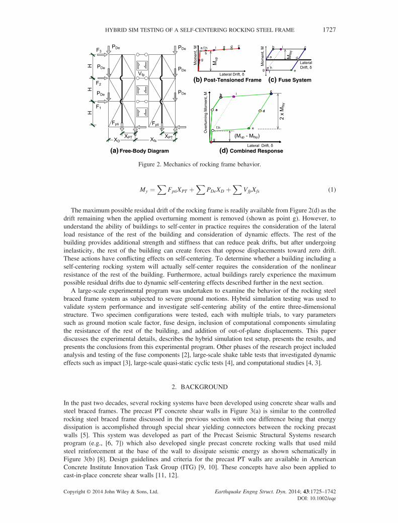
My ¼X
FptiXPT þX
PDeXD þX
VfpXfs (1)
The maximum possible residual drift of the rocking frame is readily available from Figure 2(d) as thedrift remaining when the applied overturning moment is removed (shown as point g). However, tounderstand the ability of buildings to self-center in practice requires the consideration of the lateralload resistance of the rest of the building and consideration of dynamic effects. The rest of thebuilding provides additional strength and stiffness that can reduce peak drifts, but after undergoinginelasticity, the rest of the building can create forces that oppose displacements toward zero drift.These actions have conflicting effects on self-centering. To determine whether a building including aself-centering rocking system will actually self-center requires the consideration of the nonlinearresistance of the rest of the building. Furthermore, actual buildings rarely experience the maximumpossible residual drifts due to dynamic self-centering effects described further in the next section.
A large-scale experimental program was undertaken to examine the behavior of the rocking steelbraced frame system as subjected to severe ground motions. Hybrid simulation testing was used tovalidate system performance and investigate self-centering ability of the entire three-dimensionalstructure. Two specimen configurations were tested, each with multiple trials, to vary parameterssuch as ground motion scale factor, fuse design, inclusion of computational components simulatingthe resistance of the rest of the building, and addition of out-of-plane displacements. This paperdiscusses the experimental details, describes the hybrid simulation test setup, presents the results, andpresents the conclusions from this experimental program. Other phases of the research project includedanalysis and testing of the fuse components [2], large-scale shake table tests that investigated dynamiceffects such as impact [3], large-scale quasi-static cyclic tests [4], and computational studies [4, 3].
2. BACKGROUND
In the past two decades, several rocking systems have been developed using concrete shear walls andsteel braced frames. The precast PT concrete shear walls in Figure 3(a) is similar to the controlledrocking steel braced frame discussed in the previous section with one difference being that energydissipation is accomplished through special shear yielding connectors between the rocking precastwalls [5]. This system was developed as part of the Precast Seismic Structural Systems researchprogram (e.g., [6, 7]) which also developed single precast concrete rocking walls that used mildsteel reinforcement at the base of the wall to dissipate seismic energy as shown schematically inFigure 3(b) [8]. Design guidelines and criteria for the precast PT walls are available in AmericanConcrete Institute Innovation Task Group (ITG) [9, 10]. These concepts have also been applied tocast-in-place concrete shear walls [11, 12].
(b) Post-Tensioned Frame
(d) Combined Response
(c) Fuse System
(a) Free-Body Diagram
Figure 2. Mechanics of rocking frame behavior.
HYBRID SIM TESTING OF A SELF-CENTERING ROCKING STEEL FRAME 1727
Copyright © 2014 John Wiley & Sons, Ltd. Earthquake Engng Struct. Dyn. 2014; 43:1725–1742DOI: 10.1002/eqe
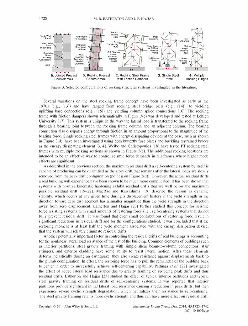
Several variations on the steel rocking frame concept have been investigated as early as the1970s (e.g., [13]) and have ranged from rocking steel bridge piers (e.g., [14]), to yieldinguplifting base connections (e.g., [15]) and yielding column splice connections [16]. The rockingframe with friction dampers shown schematically in Figure 3(c) was developed and tested at LehighUniversity [17]. This system is unique in the way the lateral load is transferred to the rocking framethrough a bearing joint between the rocking frame column and an adjacent column. The bearingconnection also dissipates energy through friction in an amount proportional to the magnitude of thebearing force. Single rocking steel frames with energy dissipating devices at the base, such as shownin Figure 3(d), have been investigated using both butterfly fuse plates and buckling restrained bracesas the energy dissipating element [3, 4]. Weibe and Christopoulos [18] have tested PT rocking steelframes with multiple rocking sections as shown in Figure 3(e). The additional rocking locations areintended to be an effective way to control seismic force demands in tall frames where higher modeeffects are significant.
As described in the previous section, the maximum residual drift a self-centering system by itself iscapable of producing can be quantified as the story drift that remains after the lateral loads are slowlyremoved from the peak drift configuration (point g on Figure 2(d)). However, the actual residual driftsa real building will experience have been shown to be much more complicated. It has been shown thatsystems with positive kinematic hardening exhibit residual drifts that are well below the maximumpossible residual drift [19–22]. MacRae and Kawashima [19] describe the reason as dynamicstability, which occurs at any given time during a displacement history if the yield strength in thedirection toward zero displacement has a smaller magnitude than the yield strength in the directionaway from zero displacement. Eatherton and Hajjar [23] further studied this concept for seismicforce resisting systems with small amounts of restoring force (i.e., self-centering systems that do notfully prevent residual drift). It was found that even small contributions of restoring force result insignificant reductions in residual drift and for the configurations studied, it was concluded that if therestoring moment is at least half the yield moment associated with the energy dissipation device,that the system will reliably eliminate residual drifts.
Another potentially important factor in controlling the residual drifts of real buildings is accountingfor the nonlinear lateral load resistance of the rest of the building. Common elements of buildings suchas interior partitions, steel gravity framing with simple shear beam-to-column connections, stairstringers, and exterior cladding have some ability to resist lateral motion. After these elementsdeform inelastically during an earthquake, they also create resistance against displacements back tothe plumb configuration. In effect, the restoring force has to pull the remainder of the building backto center in order to successfully achieve self-centering capability. Pettinga et al. [22] investigatedthe effect of added lateral load resistance due to gravity framing on reducing peak drifts and thusresidual drifts. Eatherton and Hajjar [23] studied the effect of typical interior partitions and typicalsteel gravity framing on residual drifts of self-centering systems. It was reported that interiorpartitions provide significant initial lateral load resistance causing a reduction in peak drifts, but thenexperience severe cyclic strength degradation, which neutralizes their resistance to self-centering.The steel gravity framing retains more cyclic strength and thus can have more effect on residual drift.
d. Single SteelFrame
e. MultipleRocking Hinges
b. Rocking PrecastConcrete Wall
c. Rocking Steel Framewith Friction Dampers
a. Jointed PrecastConcrete Wall
Figure 3. Selected configurations of rocking structural systems investigated in the literature.
1728 M. R. EATHERTON AND J. F. HAJJAR
Copyright © 2014 John Wiley & Sons, Ltd. Earthquake Engng Struct. Dyn. 2014; 43:1725–1742DOI: 10.1002/eqe

The hybrid simulation tests described in this paper represent a unique study in which the ability of aphysical self-centering system is tested in conjunction with computational components representing theresistance of the rest of the building.
3. EXPERIMENTAL SETUP
The design of the test specimens was based on a prototype building from the SAC studies [24]. Theprototype building is three stories tall with typical floor and roof framing shown in Figure 4 and isdesigned for a site class D location with high seismicity as given by SDS= 1.00 g and SD1=0.60 g [25]resulting in a design base shear that was 12.5% of the seismic weight assuming a response modificationfactor, R= 8.0. The seismic masses for the roof and floors were 1033 kN s2/m and 956 kNs2/m,respectively. Two dual-frame controlled rocking frame assemblies were assumed in each direction andthe large-scale tests represented 0.43 scale relative to one of these prototype frames.
The design overturning moment, Movt, was calculated as the sum of the equivalent lateral forces,such as those calculated using ASCE 7-10 [25], multiplied by their respective heights above therocking interface. The resistance to overturning moment was calculated using Eq. (1) with dead loadequal to 0, PDe= 0, and multiplied by an assumed resistance factor, ϕ = 0.9. The ratio of the designoverturning moment, Movt, to this design resistance, ϕMy, is given in Table I as the strength ratio forthe two specimen configurations. The ability of the system to eliminate drift when the forces areremoved is expressed as a self-centering ratio (SC), given by Eq. (2) as the ratio of restoringmoment due to initial post-tensioning force, Fpti, divided by the resistance opposing self-centeringdue to the fuse shear capacity, Vfp. The dead loads, PDe, were set to 0 for the large scale tests. Themoment arms, shown schematically in Figure 2(a), were measured to be XPT= 0.89m, andXfs = 2.31m. Assuming negligible post-tensioning losses, negligible fuse hardening, and ignoring thelateral resistance of the gravity framing, an SC greater than unity will result in near zero drift whenthe lateral loads are removed. After undergoing inelastic deformations, the gravity framing andnonstructural components act to resist self-centering. Although the effect of post-tensioning lossesand fuse hardening can be estimated and if desired, accounted for in Eq. (2), the nonlinear behavior
Six 9.14m Bays = 54.9m
(b) Elevation View
Fou
r 9.
14m
Bay
s =
36.
6m
(a) Plan View
Thr
ee 3
.96m
Sto
ries
= 1
1.9m
Figure 4. Prototype building.
HYBRID SIM TESTING OF A SELF-CENTERING ROCKING STEEL FRAME 1729
Copyright © 2014 John Wiley & Sons, Ltd. Earthquake Engng Struct. Dyn. 2014; 43:1725–1742DOI: 10.1002/eqe

of the rest of the building including gravity framing with shear connections and interior partitions is notas straightforward. The effect of gravity framing and nonstructural elements such as interior partitionson self-centering ability is therefore investigated separately through computational studies [23] andthrough hybrid simulation tests described later.
SC ¼X
FptiXPT þX
PDeXDXVfpXfs
(2)
Table I gives information about the six hybrid simulation tests conducted on two specimens. Bothspecimens were designed using properties that could be considered representative of systems thatmight be implemented in practice including design overturning moment resistance close to theoverturning moment demand assuming R= 8.0 and an SC close to 1.0. The two significantdifferences between specimen A5 and specimen A6 were the fuse type (degrading versusnondegrading behavior) and the type of computational module included (leaning column versusmodel capturing resistance of the rest of the building). The computational models and scale levelsare described further in the following section.
The specimen design is shown in Figure 5(a) and consists of steel wide flange sections turned tohave their flanges in the plane of the frame with gusset plates on the front and back. The uplifting
Table I. Testing program for half-scale hybrid simulation tests.
Specimen Scale levelsSystem
propertiesFuse
configurationExpected fuse
behaviorComputationalcomponent
MCE (0.69 ×Kobe) Strengthratio = 1.12SC= 1.10
Two 15.9mm fuseswith 8 linksVfp= 340 kN
Nondegradingfull hysteresis
Leaning columnonlyA5 1.10 × JMA Kobe
1.10 × JMA KobeMCE (0.69 ×Kobe) Strength
ratio = 1.13SC= 1.10
Six 6.4mm fuseswith 8 linksVfp= 349 kN
Degradingpinchedhysteresis
Buildingresistance andleaning column
A6 MCE with OOP*1.20 × JMA Kobe
MCE, maximum considered earthquake; JMA, Japan Meteorological Agency; SC, self-centering ratio.*10% of in-plane motion concurrently applied in the out-of-plane (OOP) direction.
(a) Specimen Details (Specimen A5 Shown) (b) Photograph of Specimen A6
Figure 5. Specimen layout, dimensions, and photograph.
1730 M. R. EATHERTON AND J. F. HAJJAR
Copyright © 2014 John Wiley & Sons, Ltd. Earthquake Engng Struct. Dyn. 2014; 43:1725–1742DOI: 10.1002/eqe
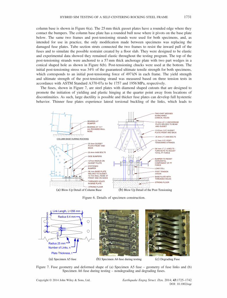
column base is shown in Figure 6(a). The 25mm thick gusset plates have a rounded edge where theycontact the bumpers. The column base plate has a rounded bull nose where it pivots on the base platebelow. The same two frames and post-tensioning strands were used for both specimens, and, asintended for use in practice, the only modification made between specimens was replacing thedamaged fuse plates. Tube section struts connected the two frames to resist the inward pull of thefuses and to simulate the possible restraint created by a floor slab. They were designed to be elasticand experimental data showed they remained elastic throughout the testing program. The top of thepost-tensioning strands were anchored to a 57mm thick anchorage plate with two part wedges in aconical shaped hole as shown in Figure 6(b). Post-tensioning chucks were used at the bottom. Theinitial post-tensioning stress was 34% of the guaranteed ultimate tensile strength for both specimens,which corresponds to an initial post-tensioning force of 497 kN in each frame. The yield strengthand ultimate strength of the post-tensioning strand was measured based on three tension tests inaccordance with ASTM Standard A370-07a to be 1757 and 1956MPa, respectively.
The fuses, shown in Figure 7, are steel plates with diamond shaped cutouts that are designed topromote the initiation of yielding and plastic hinging at the quarter point away from locations ofdiscontinuities. As such, large ductility is possible and thicker fuse plates can develop full hystereticbehavior. Thinner fuse plates experience lateral torsional buckling of the links, which leads to
(a) Blow-Up Detail of Column Base (b) Blow Up Detail of the Post-Tensioning
Figure 6. Details of specimen construction.
(a) Specimen A5 fuse (b) Specimen A6 fuse during testing (c) Degrading Fuse
Figure 7. Fuse geometry and deformed shape of (a) Specimen A5 fuse – geometry of fuse links and (b)Specimen A6 fuse during testing – nondegrading and degrading fuses.
HYBRID SIM TESTING OF A SELF-CENTERING ROCKING STEEL FRAME 1731
Copyright © 2014 John Wiley & Sons, Ltd. Earthquake Engng Struct. Dyn. 2014; 43:1725–1742DOI: 10.1002/eqe

strength degradation. Nondegrading thick fuses can be desirable for their ability to dissipate seismicenergy, whereas degrading fuses can be desirable because their resistance against restoring forcesdegrades leading to improved self-centering ability. Specimen A5 and A6 fuses were designed todevelop nondegrading or degrading response by varying the thickness from 15.9 to 6.4mm forSpecimen A5 and A6, respectively. The mean yield stress of the ASTM A36 plate material wasmeasured using four tension coupons for the 6.4mm plate and three coupons for the 15.9mm thickplate to be 274 and 317MPa, respectively. More information on design and behavior of butterflysteel fuse plates can be found in Ma et al. [2] and Eatherton and Hajjar [4].
A photograph of a test specimen is shown in Figure 5(b). The top of the loading beam is connectedto a Loading and Boundary Condition Box (LBCB) capable of controlling all six degrees of freedom.The loading beam was connected to the two frames through bidirectional load cell pins. The tests werecontrolled to maintain zero vertical force in the load cell pins and apply the displacements computed bythe hybrid simulation time stepping algorithm at the roof level based on the feedback of two stringpotentiometers. The out-of-plane degrees of freedom were controlled to have zero displacement orrotation except for one trial for Specimen A6 that was controlled to include out-of-plane displacement.Approximately 500 channels of data were recorded for each test including string potentiometers, linearpotentiometers, load cells, strain gages, linear variable differential transformers, and Krypton LEDs aswell as video cameras and digital still cameras. Additional information on instrumentation can be foundin Eatherton and Hajjar [4].
4. HYBRID SIMULATION TEST SETUP
Hybrid simulation tests were used to investigate the performance of the self-centering rocking steelframe system subjected to real ground motions in the presence of second-order gravity load effectsand the ambient building resistance. In this paper, ambient building resistance refers to the lateralload resistance of building components not typically included in computational models of the lateralload resisting system.
Two computational models were created using the OpensSEES software [26] to represent thegravity load second-order effects and the ambient building resistance. These computationalcomponents were linked to the experimental setup by using the UI-SIMCOR software [27], asschematically demonstrated in Figure 8(b). Test A5 included only one computational componentthat represented second-order gravity effects, whereas Test A6 also included a computationalcomponent representing ambient building resistance of the rest of the three-dimensional structure asshown in Figure 8(b).
The second-order gravity effects were modeled as a pinned-base leaning column with an effectivegravity load lumped at the top. The effective gravity load was found by determining the amount offorce that caused the same amount of P-Δ moment in the SDOF system as three floors of tributarygravity load [F= (∑Fihi)/H]. The tributary mass associated with the SDOF system was computed asthe mass that produced the same overturning moment as the three degree of freedom system when
Figure 8. Leaning column and hybrid simulation setup.
1732 M. R. EATHERTON AND J. F. HAJJAR
Copyright © 2014 John Wiley & Sons, Ltd. Earthquake Engng Struct. Dyn. 2014; 43:1725–1742DOI: 10.1002/eqe
subjected to a unit acceleration [m= (∑mihi)/H]. The equivalent gravity load and tributary mass areshown in Figure 8(a).
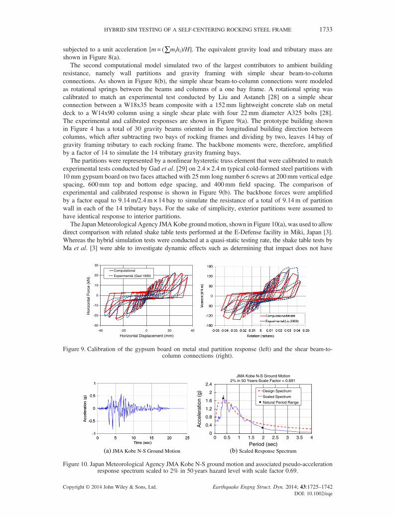
The second computational model simulated two of the largest contributors to ambient buildingresistance, namely wall partitions and gravity framing with simple shear beam-to-columnconnections. As shown in Figure 8(b), the simple shear beam-to-column connections were modeledas rotational springs between the beams and columns of a one bay frame. A rotational spring wascalibrated to match an experimental test conducted by Liu and Astaneh [28] on a simple shearconnection between a W18x35 beam composite with a 152mm lightweight concrete slab on metaldeck to a W14x90 column using a single shear plate with four 22mm diameter A325 bolts [28].The experimental and calibrated responses are shown in Figure 9(a). The prototype building shownin Figure 4 has a total of 30 gravity beams oriented in the longitudinal building direction betweencolumns, which after subtracting two bays of rocking frames and dividing by two, leaves 14 bay ofgravity framing tributary to each rocking frame. The backbone moments were, therefore, amplifiedby a factor of 14 to simulate the 14 tributary gravity framing bays.
The partitions were represented by a nonlinear hysteretic truss element that were calibrated to matchexperimental tests conducted by Gad et al. [29] on 2.4 × 2.4m typical cold-formed steel partitions with10mm gypsum board on two faces attached with 25mm long number 6 screws at 200mm vertical edgespacing, 600mm top and bottom edge spacing, and 400mm field spacing. The comparison ofexperimental and calibrated response is shown in Figure 9(b). The backbone forces were amplifiedby a factor equal to 9.14m/2.4m× 14 bay to simulate the resistance of a total of 9.14m of partitionwall in each of the 14 tributary bays. For the sake of simplicity, exterior partitions were assumed tohave identical response to interior partitions.
The JapanMeteorological Agency JMAKobe groundmotion, shown in Figure 10(a), was used to allowdirect comparison with related shake table tests performed at the E-Defense facility in Miki, Japan [3].Whereas the hybrid simulation tests were conducted at a quasi-static testing rate, the shake table tests byMa et al. [3] were able to investigate dynamic effects such as determining that impact does not have
-30
-20
-10
0
10
20
30
-40 -20 0 20 40
Computational
Experimental (Gad 1999)
Horizontal Displacement (mm)
Hor
izon
tal F
orce
(kN
)
Figure 9. Calibration of the gypsum board on metal stud partition response (left) and the shear beam-to-column connections (right).
(a) JMA Kobe N-S Ground Motion (b) Scaled Response Spectrum
0
0.4
0.8
1.2
1.6
2
2.4
0 0.5 1 1.5 2 2.5 3 3.5 4
Acc
eler
atio
n (g
)
Period (sec)
JMA Kobe N-S Ground Motion2% in 50 Years-Scale Factor = 0.691
Design Spectrum
Scaled Spectrum
Natural Period Range
Figure 10. Japan Meteorological Agency JMA Kobe N-S ground motion and associated pseudo-accelerationresponse spectrum scaled to 2% in 50 years hazard level with scale factor 0.69.
HYBRID SIM TESTING OF A SELF-CENTERING ROCKING STEEL FRAME 1733
Copyright © 2014 John Wiley & Sons, Ltd. Earthquake Engng Struct. Dyn. 2014; 43:1725–1742DOI: 10.1002/eqe

a significant effect on peak frame member forces. The ground motion was scaled to best match the designspectrum by using a least squares method over a period range of interest (0.34 to 2 s), which represents theinitial elastic period up to the maximum expected period calculated using the secant stiffness at peakexpected drift. The design response spectrum and scaled spectrum are shown in Figure 10(b). Multipletrials were conducted for both Specimens A5 and A6 including trials at the MCE level corresponding toa scale factor of 0.69 and scale factors of 1.10 and 1.20 for Specimens A5 and A6, respectively. Asgiven in Table I, one of the hybrid simulation tests for Specimen A6 also included the application ofout-of-plane motion equal to 10% of the in-plane displacements, the magnitude of which was selectedon the basis of physical limitations in the test setup.
The hybrid simulation test procedure is demonstrated schematically in Figure 8(b) as managed bythe hybrid simulation software UI-SIMCOR. For each hybrid simulation trial, the computationalmodules were started from an undamaged condition, meaning that the strength and stiffnessdegradation in the gravity connections and interior partitions was not carried over from previoustrials. The displacement for the current time step, Δ, is applied to both computational components,and a displacement reduced by the length scale factor, rL= 0.43, is applied to the experimentalsetup. The resulting forces are measured, the experimental force is divided by the force scale factor,rF = 0.43
2, and the forces are summed together. The displacement for the next time step is calculatedusing the α-OS time-stepping method [30] based on the measured force, Fi, computationally appliedmass, M, computationally applied damping, ζ = 0.02, velocity, vi, acceleration, ai, an elasticstiffness, Ke, and the current ground acceleration, ¨xig.
5. COMPUTATIONAL MODELING
A two-dimensional nonlinear analysis model of the specimen was created using the OpenSees software[26] including the effects of geometric and material nonlinearity. The frame members shown inFigure 11(a) were simulated using elastic frame elements. At the base of the frames, gap elements,near rigid in compression with zero stiffness in tension simulated the compression-only support andbumpers, these gap elements were oriented in both the horizontal and vertical directions. The modelwas built in stages to simulate expected construction sequencing. The fuse elements were notcreated until the initial PT forces were equilibrated through the frame. The struts that connect thetwo frames utilized an elastic–perfectly-plastic constitutive relationship with a truss element, butwere not found to experience yielding in any of the computational simulations of the tests or in theexperimental program. The pin connections at each end of the struts were modeled as shown inFigure 11(a) and blown up in Figure 11(b). The pin holes each had approximately 1.6mm tolerancegreater than the pin, which had a cumulative effect resulting in a total of 6.4mm displacement
Figure 11. Computational model of the controlled rocking system.
1734 M. R. EATHERTON AND J. F. HAJJAR
Copyright © 2014 John Wiley & Sons, Ltd. Earthquake Engng Struct. Dyn. 2014; 43:1725–1742DOI: 10.1002/eqe
required to go from axial tension to axial compression or vice versa. This lag was modeled using a zerolength spring that represented the pin hole tolerance as shown in Figure 11(b).
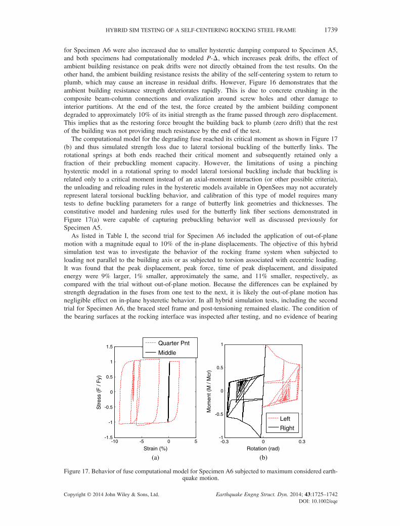
A phenomenological model was created to simulate the flexural, axial, and lateral-torsional bucklingbehavior of the fuse links that interact to create the unique shear force – shear distortion response of thefuse plates. As shown in Figure 11(c), the fuse was modeled with 12 fiber section elements using aformulation that neglects shear deformations on the element level. The depth of the fiber sectionmatched the average depth of the fuse link along that portion of its length. The thickness of thesection was set equal to the thickness of the fuse plate multiplied by the number of links beingrepresented. The material constitutive for the fuse used the Giuffre–Menegotto–Pinto model with themeasured yield stress and a combination of isotropic and kinematic hardening as demonstrated laterin Figure 17(a). Rotational springs were included at the third points of the fuse link to simulatelateral-torsional buckling. The rotational spring was a zero-length element with a cyclic behaviorusing the Pinching4 material in OpenSees. It had a steep initial stiffness up to a lateral-torsionalbuckling critical moment as shown in Figure 17(b), and then the ability of the spring to resistmoment was significantly reduced. The critical buckling moment was computed using a relationshipdefined in Eatherton and Hajjar [4] relating the experimentally obtained buckling shear forces withfuse link slenderness.
For most specimens, the constitutive model used for the post-tensioning was essentially bilinear withmodulus of elasticity equal to 202GPa, a yield stress equal to 94% of the nominal ultimate stress and apost yield stiffness equal to 1.7% of the initial modulus of elasticity.
6. RESULTS AND DISCUSSION
6.1. Specimen A5 behavior
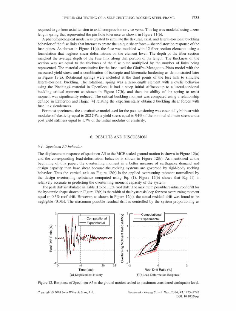
The displacement response of specimen A5 to the MCE scaled ground motion is shown in Figure 12(a)and the corresponding load-deformation behavior is shown in Figure 12(b). As mentioned at thebeginning of this paper, the overturning moment is a better measure of earthquake demand anddesign capacity than base shear because the rocking systems are governed by rigid-body rockingbehavior. Thus the vertical axis on Figure 12(b) is the applied overturning moment normalized bythe design overturning resistance computed using Eq. (1). Figure 12(b) shows that Eq. (1) isrelatively accurate in predicting the overturning moment capacity of the system.
The peak drift is tabulated in Table II to be 1.7% roof drift. The maximum possible residual roof drift forthe hysteretic shape shown in Figure 12(b) is the width of the hysteresis loop for zero overturning momentequal to 0.3% roof drift. However, as shown in Figure 12(a), the actual residual drift was found to benegligible (0.0%). The maximum possible residual drift is controlled by the system proportioning as
(a) Displacement History (b) Load-Deformation Response
0 10 20 25-2
-1
0
1
2
Roo
f Drif
t Rat
io (
%)
Time (sec)
ComputationalExperimental
-2 0 2-2
-1
0
1
2
Roof Drift Ratio (%)
ComputationalExperimental
Ove
rtur
ning
MO
men
t Rat
io (
M/M
y)
Figure 12. Response of Specimen A5 to the ground motion scaled to maximum considered earthquake level.
HYBRID SIM TESTING OF A SELF-CENTERING ROCKING STEEL FRAME 1735
Copyright © 2014 John Wiley & Sons, Ltd. Earthquake Engng Struct. Dyn. 2014; 43:1725–1742DOI: 10.1002/eqe
represented by the SC, SC=1.10. The actual residual drifts are often much smaller than the maximumpossible residual drifts in systems that have any restoring force component due to increased probabilityof yielding toward zero displacement as described in the background section. The hysteretic energydissipation is also related to the SC and because the SC is just slightly larger than unity, the hystereticenergy is shown to be approximately the largest flag shape area possible while still limiting the roofdrift when the overturning moment is removed.
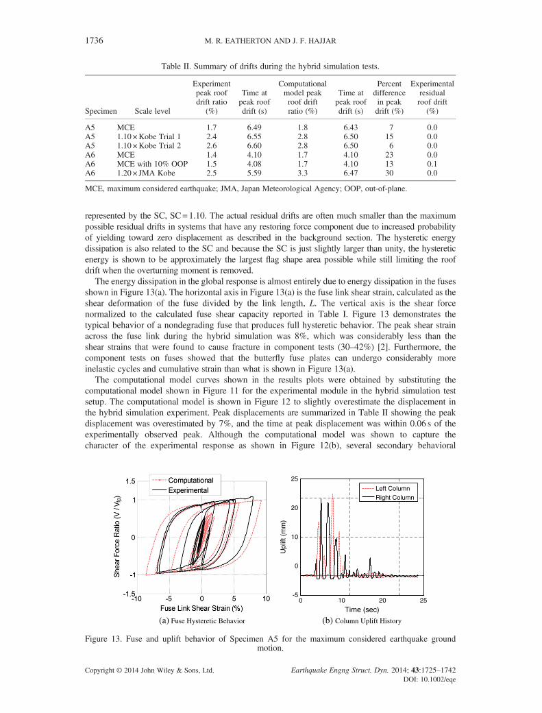
The energy dissipation in the global response is almost entirely due to energy dissipation in the fusesshown in Figure 13(a). The horizontal axis in Figure 13(a) is the fuse link shear strain, calculated as theshear deformation of the fuse divided by the link length, L. The vertical axis is the shear forcenormalized to the calculated fuse shear capacity reported in Table I. Figure 13 demonstrates thetypical behavior of a nondegrading fuse that produces full hysteretic behavior. The peak shear strainacross the fuse link during the hybrid simulation was 8%, which was considerably less than theshear strains that were found to cause fracture in component tests (30–42%) [2]. Furthermore, thecomponent tests on fuses showed that the butterfly fuse plates can undergo considerably moreinelastic cycles and cumulative strain than what is shown in Figure 13(a).
The computational model curves shown in the results plots were obtained by substituting thecomputational model shown in Figure 11 for the experimental module in the hybrid simulation testsetup. The computational model is shown in Figure 12 to slightly overestimate the displacement inthe hybrid simulation experiment. Peak displacements are summarized in Table II showing the peakdisplacement was overestimated by 7%, and the time at peak displacement was within 0.06 s of theexperimentally observed peak. Although the computational model was shown to capture thecharacter of the experimental response as shown in Figure 12(b), several secondary behavioral
Table II. Summary of drifts during the hybrid simulation tests.
Specimen Scale level
Experimentpeak roofdrift ratio
(%)
Time atpeak roofdrift (s)
Computationalmodel peakroof driftratio (%)
Time atpeak roofdrift (s)
Percentdifferencein peakdrift (%)
Experimentalresidualroof drift
(%)
A5 MCE 1.7 6.49 1.8 6.43 7 0.0A5 1.10 ×Kobe Trial 1 2.4 6.55 2.8 6.50 15 0.0A5 1.10 ×Kobe Trial 2 2.6 6.60 2.8 6.50 6 0.0A6 MCE 1.4 4.10 1.7 4.10 23 0.0A6 MCE with 10% OOP 1.5 4.08 1.7 4.10 13 0.1A6 1.20 × JMA Kobe 2.5 5.59 3.3 6.47 30 0.0
MCE, maximum considered earthquake; JMA, Japan Meteorological Agency; OOP, out-of-plane.
(a) Fuse Hysteretic Behavior (b) Column Uplift History
0 10 20 25-5
0
10
20
25
Time (sec)
Upl
ift (
mm
)
Left ColumnRight Column
Figure 13. Fuse and uplift behavior of Specimen A5 for the maximum considered earthquake groundmotion.
1736 M. R. EATHERTON AND J. F. HAJJAR
Copyright © 2014 John Wiley & Sons, Ltd. Earthquake Engng Struct. Dyn. 2014; 43:1725–1742DOI: 10.1002/eqe

phenomena contributed to differences. The idealized initial system behavior has sharp transitions instiffness as shown in Figure 2(d) although uneven bearing between rocking columns in the actualspecimen caused lower initial stiffness and a rounding of these sharp transitions as demonstrated inthe experiments and supported by analysis in Eatherton and Hajjar [4]. The computational modelingalso did not incorporate some sources of flexibility such as sliding at the base of the frames, whichis evidenced by horizontal shifts in the experimental response at 0.6My shown in Figure 12(b) orflexibility of the PT connection to the strong floor associated with the base assembly shown inFigure 6(b). The sliding was measured to be approximately 5mm for both Specimens A5 and A6.Figure 13(a) shows that the computational model of the fuse captured the strength and stiffness ofthe fuse well.
Figure 13(b) shows the uplift history for both column bases of the right frame. The peak uplift isshown to be 21mm, which is well within the design maximum uplift accommodated by thebumpers that is more than 100mm. Figure 13(b) shows that at the end of the ground motion, bothcolumns come to rest with near zero uplift. It can also be demonstrated using the uplift data that theuplift ratio calculated as the uplift divided by the distance to the pivot point is almost identical to theroof drift ratio implying that the frame undergoes rigid body rotation with negligible elasticdeformations.
Because the performance at the MCE level was more than satisfactory, two trials were performed ata larger scale level. The scale level was increased from 0.69 for the MCE level event to 1.10 or 69%larger than the MCE motion. Two trials were conducted with the same earthquake ground motion andscaling to investigate degradation in the system performance. The load-deformation response for bothtrials is shown in Figure 14(a), and the fuse behavior is shown in Figure 14(b). As shown, there wasalmost no degradation in behavior between the trials. There was an 8% increase in the peakdisplacements listed in Table II from one trial to the next. The fuse behavior shown in Figure 14(b)did not appear to degrade at all. The peak shear strain across the fuse link was 15%, which was stillonly half the shear strain that caused fractures in the tests by Ma et al. [2]. In short, Specimen A5was subjected to three infrequent and large earthquake ground motions without any repairs inbetween, and the residual roof drift ratio was 0.0% after every run, and no inelasticity was observedoutside the fuses. This implies that a well-designed self-centering rocking frame system may notneed structural repairs, nor even need to have the fuse replaced after a large earthquake.
6.2. Specimen A6 behavior
Specimen A6 used thinner degrading fuse plates and included the computational modules simulatingambient building resistance. As shown in Figure 15, the peak displacements for a trial with a 1.20scale factor produced similar peak displacements as the Specimen A5 nondegrading fuse
(a) Load-Deformation Response (b) Fuse Hysteretic Response
-3 -2 -1 0 1 2 3-2
-1
0
1
2
Roof Drift Ratio (%)
Trial 1Trial 2
-15 -10 -5 0 5 10 15-1.5
-1
-0.5
0
0.5
1
1.5
Fuse Link Shear Strain (%)
Trial 1Trial 2
Ove
rtur
ning
MO
men
t Rat
io (
M/M
y)
Figure 14. System and fuse response for Specimen A5 subjected to two trials of the JMA Kobe groundmotion scaled by 1.10.
HYBRID SIM TESTING OF A SELF-CENTERING ROCKING STEEL FRAME 1737
Copyright © 2014 John Wiley & Sons, Ltd. Earthquake Engng Struct. Dyn. 2014; 43:1725–1742DOI: 10.1002/eqe

configuration subjected to the Japan Meteorological Agency JMA Kobe ground motion with a 1.10scale factor. There are several factors that affect the peak drifts of Specimen A5 as compared withSpecimen A6. First, the peak drifts were reduced because of the added resistance provided by therest of the building. It is shown in Figure 16 that the ambient building resistance reached anoverturning moment resistance equal to the design overturning capacity of the rocking frame system,My. This significant addition of resistance surely caused reduction in the peak drifts. However, thereduced energy dissipation associated with fuse degradation likely counteracted this effect as thehysteretic damping was significantly reduced.
The reduction in energy dissipation capacity is demonstrated by the shape of the hysteresis loops.The height of the self-centering flag is reduced by approximately 50% compared with thenondegrading Specimen 5 that has a similar SC. Some guidance for minimum energy dissipation inself-centering systems is provided in Seo and Sause [31] and the American Concrete Institute [9].Figure 15(b) shows the response of the system after two previous tests at the MCE level in whichthe fuse buckled and began degrading. The response shown in Figure 15 demonstrates that the self-centering rocking frame system with a degrading fuse was able to survive three large earthquakesground motions and still limit peak drifts and eliminate residual drifts.
Ambient building resistance is expected to have two opposing effects on self-centering. First, thepeak displacements are reduced because of the added lateral load resistance. Because the peak drifts
(a) System Displacement History (b) Load-Deformation Response
0 10 20 25-3
-2
-1
0
1
2
3
4
Roo
f Drif
t Rat
io (
%)
Time (sec)
ComputationalExperimental
-4 -2 0 2 4
-2
-1
0
1
2 ComputationalExperimental
Ove
rtur
ning
MO
men
t Rat
io (
M/M
y)
Figure 15. Response of SpecimenA6 to the JapanMeteorological Agency JMAKobe groundmotion scaled by 1.2.
-3 -2 -1 0 1 2 3-1.5
-1
-0.5
0
0.5
1
1.5
Roof Drift Ratio (%)
Leaning ColumnAmbient Bldg Resistance
Ove
rtur
ning
MO
men
t Rat
io (
M/M
y)
Figure 16. Computational component responses for Specimen A6 subjected to Japan MeteorologicalAgency Kobe ground motion scaled by 1.2.
1738 M. R. EATHERTON AND J. F. HAJJAR
Copyright © 2014 John Wiley & Sons, Ltd. Earthquake Engng Struct. Dyn. 2014; 43:1725–1742DOI: 10.1002/eqe
for Specimen A6 were also increased due to smaller hysteretic damping compared to Specimen A5,and both specimens had computationally modeled P-Δ, which increases peak drifts, the effect ofambient building resistance on peak drifts were not directly obtained from the test results. On theother hand, the ambient building resistance resists the ability of the self-centering system to return toplumb, which may cause an increase in residual drifts. However, Figure 16 demonstrates that theambient building resistance strength deteriorates rapidly. This is due to concrete crushing in thecomposite beam-column connections and ovalization around screw holes and other damage tointerior partitions. At the end of the test, the force created by the ambient building componentdegraded to approximately 10% of its initial strength as the frame passed through zero displacement.This implies that as the restoring force brought the building back to plumb (zero drift) that the restof the building was not providing much resistance by the end of the test.
The computational model for the degrading fuse reached its critical moment as shown in Figure 17(b) and thus simulated strength loss due to lateral torsional buckling of the butterfly links. Therotational springs at both ends reached their critical moment and subsequently retained only afraction of their prebuckling moment capacity. However, the limitations of using a pinchinghysteretic model in a rotational spring to model lateral torsional buckling include that buckling isrelated only to a critical moment instead of an axial-moment interaction (or other possible criteria),the unloading and reloading rules in the hysteretic models available in OpenSees may not accuratelyrepresent lateral torsional buckling behavior, and calibration of this type of model requires manytests to define buckling parameters for a range of butterfly link geometries and thicknesses. Theconstitutive model and hardening rules used for the butterfly link fiber sections demonstrated inFigure 17(a) were capable of capturing prebuckling behavior well as discussed previously forSpecimen A5.
As listed in Table I, the second trial for Specimen A6 included the application of out-of-planemotion with a magnitude equal to 10% of the in-plane displacements. The objective of this hybridsimulation test was to investigate the behavior of the rocking frame system when subjected toloading not parallel to the building axis or as subjected to torsion associated with eccentric loading.It was found that the peak displacement, peak force, time of peak displacement, and dissipatedenergy were 9% larger, 1% smaller, approximately the same, and 11% smaller, respectively, ascompared with the trial without out-of-plane motion. Because the differences can be explained bystrength degradation in the fuses from one test to the next, it is likely the out-of-plane motion hasnegligible effect on in-plane hysteretic behavior. In all hybrid simulation tests, including the secondtrial for Specimen A6, the braced steel frame and post-tensioning remained elastic. The condition ofthe bearing surfaces at the rocking interface was inspected after testing, and no evidence of bearing
(a) (b)
-10 -5 0 5-1.5
-1
-0.5
0
0.5
1
1.5
Strain (%)
Str
ess
(F /
Fy)
Quarter Pnt
Middle
-0.3 0 0.3-1
-0.5
0
0.5
1
Rotation (rad)
Mom
ent (
M /
Mcr
)
Left
Right
Figure 17. Behavior of fuse computational model for Specimen A6 subjected to maximum considered earth-quake motion.
HYBRID SIM TESTING OF A SELF-CENTERING ROCKING STEEL FRAME 1739
Copyright © 2014 John Wiley & Sons, Ltd. Earthquake Engng Struct. Dyn. 2014; 43:1725–1742DOI: 10.1002/eqe
indentions or other damage was found. Although the column base details performed well in allowinguplift and pivoting of the column without observable damage, tolerances allowed some sliding of therocking frames. As shown in Table II, the second trial for Specimen A6 experienced a residual roofdrift of 0.1% that was due to sliding of the rocking frames between the bumpers. Some tolerancewas required between the bumpers and the rocking frame to facilitate the desired erectionsequencing. However, as described in Eatherton and Hajjar [4], in further tests, shims were addedbetween the bumper and rocking frame, which eliminated the sliding.
6.3. Summary of peak and residual drifts
A summary of all the peak roof drifts and residual roof drifts are tabulated in Table II includingpredictions from the computational model. The accuracy of the computational model in predictingpeak drifts was found to be better for the nondegrading fuses. The tabulated residual roof driftsgiven in Table II clearly show that the self-centering rocking steel frame system is capable ofessentially eliminating residual drift after very large earthquake ground motions includingconsideration of the destabilizing P-Δ effects and ambient building resistance. These results areconsistent with the findings of a companion set of shake table tests that were conducted at the E-Defensefacility in Miki, Japan [3] in which the rocking steel frames were shown to exhibit negligible residualdrifts and focused structural damage in replaceable fuse elements after being subjected to numerous largeearthquake ground motions.
7. CONCLUSIONS
The self-centering rocking frame system consists of concentrically braced steel frames that are allowedto rock relative to the foundation with vertical post-tensioning that closes the uplifting gap thuscreating a restoring force and steel butterfly fuse plates that dissipate seismic energy. A large-scalehybrid simulation testing program was conducted including six tests on two specimens. Through allof the hybrid simulation tests, the frame and post-tensioning remained elastic, demonstrating that thesystem could be repaired after a large earthquake by replacing the fuse plates. It was shown thatnondegrading butterfly fuse plates are capable of undergoing multiple large ground motions withoutdeterioration of their strength or stiffness. It is therefore concluded that nondegrading butterfly fusesthat are designed to limit their peak fuse shear strain to 15%, which is half the magnitude thatcaused fracture in a separate testing program, that the fuse plates may not need to be replaced afterone or two large earthquakes.
The residual drifts after every hybrid simulation test were near zero. It is concluded that the self-centering rocking steel frames are therefore capable of excellent self-centering ability. The resistanceof the rest of the building was considered in the hybrid simulation through computationalcomponents simulating the resistance of steel gravity framing and interior partitions. It was foundthat the resistance of the rest of the building degrades significantly and with it the resistance to self-centering degrades. At the same time, the resistance of the rest of the building also acts to reducepeak drifts. The peak and residual roof drift ratios for Specimen A6 considering the resistances ofthe rest of building were 1.4% and 0.0%, respectively when subjected to an MCE level groundmotion, demonstrating relatively small peak drifts while not causing residual drifts. Although this isbased on one prototype building configuration, a larger computational study in Eatherton and Hajjar[23] found that the resistance of the rest of the building can cause significant reduction in peak drifts(by as much as 2.5 times for the range of configurations investigated), whereas residual driftsincreased, but remained relatively small (less than 0.25% for the residual roof drift ratio).
Based on hybrid simulation tests, it has been shown that the self-centering rocking steel frames cansatisfy enhanced seismic performance objectives as compared with conventional systems related totargeted structural repair and are thus expected to experience less business downtime and repaircosts. The self-centering rocking frame system satisfies these performance objectives byconcentrating all inelasticity in replaceable fuse elements and virtually eliminating residual drift.
1740 M. R. EATHERTON AND J. F. HAJJAR
Copyright © 2014 John Wiley & Sons, Ltd. Earthquake Engng Struct. Dyn. 2014; 43:1725–1742DOI: 10.1002/eqe
ACKNOWLEDGEMENTS
This material is based upon work supported by the National Science Foundation under Grant No. (CMMI-0530756), the American Institute of Steel Construction, Stanford University, and the University of Illinois atUrbana-Champaign. In-kind funding was provided by Tefft Bridge and Iron of Tefft, Indiana, MC Detailersof Merrillville, Indiana, Munster Steel Co. Inc. of Munster, Indiana, Infra-Metals of Marseilles, Indiana, andTextron/Flexalloy Inc. Fastener Systems Division of Indianapolis, Indiana. The authors thank researchcollaborators Greg Deierlein, Helmut Krawinkler, and Sarah Billington; graduate students, Xiang Ma, KerryHall, Alejandro Pena, Eric Borchers, and Paul Cordova; practicing structural engineers, David Mar andGregory Luth; and our Japanese collaborators for their contributions to this research. The LBCB OperationsManager and LBCB Plug-in used in this research were developed by Narutoshi Nakata, Matt Eatherton, OhSung Kwon, Sung Jig Kim, and Curtis Holub with support from NEES@UIUC, Grant No. A6000 SBCNEES OMSA-2004, and the Mid-America Earthquake Center, NSF Grant No. EEC-9701785. Anyopinions, findings, and conclusions or recommendations expressed in this material are those of the authorsand do not necessarily reflect the views of the National Science Foundation or other sponsors. [Correctionmade here after initial online publication.]
REFERENCES
1. Bradley BA, Curbinovski M. Near-source strong ground motions observed in the 22 February 2011 Christchurchearthquake. Seismological Research Letters 2011; 82(6):853–865.
2. Ma X, Borchers E, Pena A, Krawinkler H, Billington S, Deierlein GG. Design and behavior of steel shear plates withopenings as energy dissipating fuses, blume earthquake Eng. Center TR #173, Stanford University, 2010.
3. Ma X, Krawinkler H, Deierlein GG. Seismic design and behavior of self-centering braced frame with controlledrocking and energy dissipating fuses, blume earthquake Eng. Center TR #174, Stanford University, 2011.
4. Eatherton MR, Hajjar JF. Large-scale cyclic and hybrid simulation testing and development of a controlled-rockingsteel building system with replaceable fuses, Report No. NSEL-025, Newmark Structural Engineering LaboratoryReport Series, Univ. of Illinois at Urbana-Champaign, Urbana, Illinois, 2010.
5. Nakaki S, Stanton J, Sritharan S. An overview of the PRESSS five-story precast test building. PCI Journal 1999;33(2):26–39.
6. Priestley MJN, Sritharan S, Conley JR, Pampanin S. Preliminary results and conclusions from the PRESS five-storyprecast concrete test building. PCI Journal 1999; 44(6):42–67.
7. Kurama YC, Pessiki S, Sause R, Lu L-W. Seismic behavior and design of unbonded post-tensioned precast concretewalls. PCI Journal 1999; 44(3):72–89.
8. Holden T, Restrepo J, Mander JB. Seismic performance of precast reinforced and prestressed concrete walls. ASCEJournal of Structural Engineering 2003; 129(3):286–296.
9. ACI ITG. Acceptance Criteria for Special Unbonded Post-Tensioned Precast Structural Walls Based on ValidationTesting. ACI ITG-5.1-07, American Concrete Institute, 2007.
10. ACI ITG. Requirements for Design of a Special Unbonded Post-Tensioned Precast Shear Wall Satisfying ACI ITG-5.1 and Commentary. ACI ITG-5.2-09, American Concrete Institute: Farmington Hills, MI, 2009; 25.
11. Panian L, Steyer M, Tipping S. Post-tensioned concrete walls for seismic resistance. Journal of the Post-TensioningInstitute 2007; 5(1):7–16.
12. Luth GP, Sargunuraj S, Krawinkler H, McDonald B. USC school of cinema – an example of repairable performance-based design. SEAOC 2008 Convention Proceedings 2008; 20.
13. Clough RW, Huckelbridge AA. Preliminary experimental study of seismic uplift of a steel frame. EarthquakeEngineering Research Center (EERC) Report No. UCB/EERC-77-22, 1977.
14. Pollino M, Bruneau M. Analytical and experimental investigation of a controlled rocking approach for seismicprotection of bridge steel truss piers, Technical Report MCEER-08-0003, 2008.
15. Midorikawa M, Azuhata T, Ishihara T, Wada A. Shaking table tests on seismic response of steel braced frames withcolumn uplift. Earthquake Engineering and Structural Dynamics 2006; 35:1767–1785.
16. Wada A, Yamada S, Fukuta O, Tanigawa M. Passive controlled slender structures having special devises at columnconnections. 7th International Seminar on Seismic Isolation, Passive Energy Dissipation and Active Control ofVibrations of Structures, Assisi, Italy, October 2–5, 2001.
17. Sause R, Ricles JM, Roke DA, Chancellor NB, Gonner NP. Seismic performance of a self-centering-rockingconcentrically-braced frame. Proceeding of the 9th U.S. National and 10th Canadian Conference on EarthquakeEngineering, Toronto, Ontario, Canada, Paper No. 1330, July 25-29, 2010.
18. Wiebe L, Christopoulos C. Mitigation of higher mode effects in base-rocking systems by using multiple rockingsections. Journal of Earthquake Engineering 2009; 13(S1):83–108.
19. MacRae GA, Kawashima K. Post-earthquake residual displacements of bilinear oscillators. Earthquake Engineeringand Structural Dynamics 1997; 26(7):701–716.
20. Ruiz-Garcia J, Miranda E. Residual displacement ratios for assessment of existing structures. EarthquakeEngineering and Structural Dynamics 2006; 35:315–336.
21. Christopoulos C, Pampanin S, Priestley MJN. Performance-based seismic response of frame structures includingresidual deformations, part I: single-degree of freedom systems. Journal of Earthquake Engineering 2003; 7(1):97–118.
HYBRID SIM TESTING OF A SELF-CENTERING ROCKING STEEL FRAME 1741
Copyright © 2014 John Wiley & Sons, Ltd. Earthquake Engng Struct. Dyn. 2014; 43:1725–1742DOI: 10.1002/eqe
22. Pettinga D, Christopoulos C, Pampanin S, Priestley N. Effectiveness of simple approaches in mitigating residualdeformations in buildings. Earthquake Engineering and Structural Dynamics 2007; 36(12):1763–1783.
23. Eatherton M, Hajjar JF. Residual drifts of self-centering systems including effects of ambient building resistance.Earthquake Spectra 2011; 27(3):719–744.
24. Gupta A, Krawinkler H. Seismic demands for performance evaluation of steel moment resisting frame structures.John A. Blume Earthquake Engineering Center Report Number 132, 1999.
25. ASCE/SEI 7-05. Minimum design loads for buildings and other structures. Published by the American Society ofCivil Engineers (ASCE), Prepared by the Structural Engineering Institute of ASCE, 2010.
26. Mazzoni S, McKenna F, Scott MH, Fenves GL. Open system for earthquake engineering simulation user command-language manual, OpenSees version 2.0, Pacific Earthquake Engineering Research Center, University of California,Berkeley, CA, 2009.
27. Kwon O-S, Nakata N, Park K-S, Elnashai A, Spencer B. UI-SIMCOR user manual and examples for UI-SIMCORv2.6 and NEES-SAM v2.0, 2007. available from NEES Forge website: http://neesforge.nees.org/
28. Liu J, Astaneh-Asl A. Cyclic testing of simple connections including effects of slab. Journal of StructuralEngineering, ASCE 2000; 126(1):32–39.
29. Gad EF, Chandler AM, Duffield CF, Stark G. Lateral behavior of plasterboard-clad residential steel frames. Journalof Structural Engineering, ASCE 1999; 125(1):32–39.
30. Combescure D, Pegon P. α-operator splitting time integration technique for pseudodynamic testing error propagationanalysis. Soil Dynamics and Earthquake Engineering 1997; 16:427–443.
31. Seo C-Y, Sause R. Ductility demands on self-centering systems under earthquake loading. ACI Structural Journal2005; 102(2):275–285.
1742 M. R. EATHERTON AND J. F. HAJJAR
Copyright © 2014 John Wiley & Sons, Ltd. Earthquake Engng Struct. Dyn. 2014; 43:1725–1742DOI: 10.1002/eqe