Embed Size (px)
Citation preview
401
Hybrid Materials. Synthesis, Characterization, and Applications. Edited by Guido KickelbickCopyright © 2007 Wiley-VCH Verlag GmbH & Co. KGaA, WeinheimISBN: 978-3-527-31299-3
10Electronic and Electrochemical Applications of Hybrid MaterialsJason E. Ritchie
10.1Introduction
The goal of this chapter is to illustrate for the reader several interesting elec-tronic and electrochemical applications for hybrid organic/inorganic and com-posite materials. Examples have been chosen which are particularly illustrative ofthe hybrid materials application. This chapter is not intended to be a thorough review of the literature in this area, rather as a description of interesting applica-tions of hybrid materials. A somewhat broad variety of electrochemically active organic–inorganic hybrids have been covered including the traditional incorpora-tion of organic species into sol–gel materials, and also the incorporation of conductive particles into sol–gel materials, some siloxane based materials, and theso-called “polyether hybrid redox melts” produced through the organic modifica-tion of inorganic redox molecules.
New methods of materials synthesis must be developed in order to realize thenext generation of electrochemically-active materials. This is a very broad field inwhich many challenges remain unsolved. There are many materials challenges inelectrochemistry that may potentially find solutions in hybrid materials, includingfinding new materials that display substantial anhydrous proton conductivity at elevated temperatures for proton-exchange membrane (PEM) fuel cell applications.
Nanocomposite and hybrid materials are of special interest in the field of elec-trochemistry because of the potential synergistic interaction of the component ma-terials. That is, these hybrids may exhibit properties that are significantly differentfrom the average of the individual components. For example, while most sol–gelmaterials are dimensionally stable electrical insulators, the addition of a liquid-likeconductive material can create a dimensionally stable, ionically conductive hybridmaterial. The rational design of hybrid materials allows for specific physical andelectrochemical properties to be incorporated into the resulting material. As men-tioned above, sol–gel oxide materials are frequently incorporated into materials inorder to increase the dimensional stability of the resulting hybrid. In many cases,
the organic components of the hybrid materials can be chemically tailored by covalent attachment of functional groups in order to add desired functionality tothe material.
Sol–gel chemistry is a convenient, rapid, and extremely flexible method for creating advanced ceramics, glasses, and thin films. There are several methods for producing electrochemically-active hybrid materials using sol–gel chemistry.These hybrid materials can be described according to the Sanchez and Ribotscheme as either Class I, which contain weak bonds between organic and inor-ganic components, and Class II materials, which contain strong covalent bondsbetween organic and inorganic components.
Electrochemically active hybrid materials generally provide several advantagesover their constituent components. The properties of a hybrid material are fre-quently synergistic combinations of the properties of its constituent components.For example, a hybrid material may offer advantages in processibility and stabil-ity (like a solid), while maintaining the ion and small molecule diffusion proper-ties of a liquid. The ability to design a material that contains desirable propertieswhile minimizing undesirable properties is very attractive. Hybrid materials canalso combine the electrical conductivity properties of solid materials with the ionicconductivity properties of liquid materials. This combination can lead to hybridmaterials with applications in electrochemical power sources such as fuel cell andbattery electrolytes and catalytic electrode materials.
This chapter will discuss several electrical applications of hybrid materials including their use in H+- and Li+-conducting electrolytes, for fuel cell and battery applications, the use of hybrid materials in electrochemical sensors, and the use of hybrid materials in the creation of electrochemically generated luminescence.
10.2Historical Background
One of the first applications of electrochemically active hybrid materials was theformation of chemically modified electrodes consisting of either siloxane polymerslabeled with redox active groups, or trichlorosilane labeled redox molecules in the late 1970s. These chemically modified electrodes were prepared in order to examine how redox molecules behaved when confined to an electrode’s surface.These systems showed surface confined redox waves, and electron hoppingthrough mixed valent layers of the redox films. In the mid-1980s, both class I andclass II redox-active hybrids consisting of redox molecules encapsulated in asol–gel glass and a redox-active ormocers were prepared in order to study the behavior of redox molecules in solid materials. In the last 10–15 years, electro-chemically active composite materials have become a popular way to create ionconducting electrolytes, chemical sensors, and electrochromic devices with tai-lored physical and chemical properties. This chapter will discuss many of the elec-trochemical applications of this exciting class of hybrid materials.
402 10 Electronic and Electrochemical Applications of Hybrid Materials
10.3Fundamental Mechanisms of Conductivity in Hybrid Materials
There is great interest in the basic mechanisms of ionic and electron transport inpolymers and hybrid materials. These mechanisms are especially relevant to thedesign and synthesis of the next generation of electrolytes and electrode materi-als for fuel cell and battery applications. This section will discuss the basic issuesand mechanism(s) of electrical conductivity in composite materials, and of the ionic conductivity of Li+ and H+ ions.
The electrical properties of solid, inorganic materials can be classified into fourcategories: insulator, semiconductor, metal, and superconductor. Generally, solid-state inorganic materials do not show appreciable ionic conductivity due to the extremely slow mass transport of atoms within the solid-state structure. There are countless examples of liquid organic-based systems that display large ionic conductivities. Frequently, these organic systems are electrical insulators and generally respond to applied voltages with ionic motion (in organic species, theHOMO-LUMO energy gap is frequently large, giving large activation energies todelocalized electron motion). The combination of inorganic and organic materialsallows for the formation of hybrid materials that combine electrical and ionic con-ductivities in interesting ways. For example, the introduction of ionic conduc-tivity to solid materials allows for the synthesis of semi-solid electrolytes for lithium-polymer batteries, and PEM fuel cells. In addition, the introduction of elec-trical conductivity to insulating polymers allows for the creation of stable elec-trochromic films and electrochemical sensors.
10.3.1Electrical Conductivity
While many inorganic oxides are insulators, there are several examples of inor-ganic oxides which display substantial electrical conductivity (e.g. tungsten oxide,vanadium pentoxide, and manganese oxide). In these conducting oxides, the elec-tronic conductivity results from a mixture of oxidation states on the metal atoms.In vanadium oxide, this mixture of oxidation states allows an electron to hop froma reduced vanadium site to an adjacent vanadium site in a higher oxidation state.This hopping typically occurs with a small activation barrier of less than 0.5eV.This small activation barrier to conductivity indicates that you would expect to seesemiconducting (not-metallic) behavior in this material (similarly to other smallband gap semiconductors). Furthermore, the bulk redox state of these conductingoxides can be adjusted electrochemically, and typically produce a color change inthe material. For example, vanadium oxide (V2O5) changes from a yellow color todeep blue upon reduction to V2O4, or upon intercalation of Li to form LixV2O5. Inaddition, tungsten oxide (WO3) changes from a yellow color to a greenish-bronzecolor upon intercalation of Na forming the well-known sodium tungsten bronze(NaxWO3).
10.3 Fundamental Mechanisms of Conductivity in Hybrid Materials 403
In addition to the mixed-valent oxides, there are several examples of semicon-ducting oxides including ZnO, BaTiO3, and TiO2 that are wide band gap intrinsicsemiconductors. An intrinsic semiconductor has a valence band, whose electron-ic states are completely occupied with electrons, separated from a empty conduc-tion band (i.e. electronic states that are unoccupied by electrons) by an energy gap(no electronic states). In order for electrons to participate in electrical conduc-tivity, an electron must be promoted from the valence band across the band gapto the empty conduction band. Once the electron is transferred to the conductingband, it is free to move from electronic state to state, and therefore be mobilethroughout the material (the “hole” left behind in the valence band is also mobileand contributes to electrical conductivity).
Intrinsic semiconductors can frequently be easily converted to much more con-ductive narrow band gap, extrinsic n-type semiconductors by the addition of n-type dopants. These n-type dopants have more electrons than the parent atoms(atoms to the right of the parent atom on the periodic table) and add electron den-sity into bands near the vacant conduction band. For example, n-type dopants forintrinsic silicon include P, As, and Sb as they each contain one more valence elec-tron than Si. The addition of a small n-type dopant band effectively narrows theband gap of the material and leads to larger electrical conductivities. These mate-rials are extensively used in photoelectrochemical applications such as sensitizersin photovoltaic cells.
In addition to materials that display bulk electrical conductivity, composites con-taining electrically conducting components have been synthesized by the entrap-ment of small particles of conductive material within an insulating matrix. In oneexample of this type of material, carbon-ceramic composite electrodes have beenconstructed through the incorporation of conductive graphite particles into a sili-cate matrix. In these types of hybrid materials, the electrical conductivity of thecomposite is dependant on the formation of an electrical percolation network ofconducting particles. That is the concentration of the conductive particles must behigh enough that they form a closely connected and continuous network that spansthe hybrid material. A composite formed with a low concentration of conductingparticles would not show electrical conductivity because each particle would be isolated and not part of a continuous electrical network. While these materials appear to be electrical conductors, it would be more accurate to say that they con-tain electrically conductive pathways within the composite material. In addition,the large number of particle-particle junctions can create a significant amount ofelectrical resistance, which may limit the overall conductivity. Furthermore, theelectrical conductivity is also sensitive to the number of parallel conduction path-ways, that is, the more concentrated the conductive particles, the more likely it isthat the random distribution of the particles in the material will form a large num-ber of conductive pathways, which increases the measured conductivity.
Similar conducting hybrid composites that have the components reversed (i.e.electrically insulating inorganic particles with electrically conducting organic polymers) can also be easily prepared. In one example of this type of material, acomposite of oxidized polypyrrole (PPy) and ZrO2 nanoparticles lead to a composite
404 10 Electronic and Electrochemical Applications of Hybrid Materials
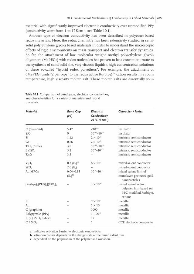
material with significantly improved electronic conductivity over unmodified PPy(conductivity went from 1 to 17Scm−1, see Table 10.1).
Another type of electron conductivity has been described in polyether-based redox materials. Here, the redox chemistry has been extensively studied in semi-solid poly(ethylene glycol) based materials in order to understand the microscopiceffects of rigid environments on mass transport and electron transfer dynamics.So far, the attachment of low molecular weight methyl poly(ethylene glycol)oligomers (MePEGs) with redox molecules has proven to be a convenient route tothe synthesis of semi-solid (i.e. very viscous liquids), high concentration solutionsof these so-called “hybrid redox polyethers”. For example, the attachment of6MePEG7 units (2 per bipy) to the redox active Ru(bipy)3
2+ cation results in a roomtemperature, high viscosity molten salt. These molten salts are essentially solu-
10.3 Fundamental Mechanisms of Conductivity in Hybrid Materials 405
Table 10.1 Comparison of band gaps, electrical conductivities,and characteristics for a variety of materials and hybridmaterials.
Material Band Gap Electrical Character / Notes(eV) Conductivity
25 °C (Scm−1)
C (diamond) 5.47 <10−12 insulatorSiO2 9 10−12–10−18 insulatorSi 1.12 2 × 10⁻⁵ intrinsic semiconductorGe 0.66 2 × 10⁻² intrinsic semiconductorTiO2 (rutile) 3.0 10−12–10−18 intrinsic semiconductorBaTiO3 3.2 10−8–10−15 intrinsic semiconductorZnO 3.2 – intrinsic semiconductor
V2O5 0.2 (EA)[a] 8 × 10⁻⁴ mixed-valent conductorWO3 2.6 (Eg) – mixed-valent conductorAu MPCs 0.04–0.15 10−3–10−5 mixed valent film of
(EA)[b] monolayer protected goldnanoparticles
[Ru(bpy)3(PEG)2](ClO4)2 – 3 × 10⁻⁸ mixed valent redox polymer film based onPEG-modified Ru(bipy)3
cationsPt – 9 × 10⁴ metallicAu – 5 × 10⁵ metallicC (graphite) – 1000 metallicPolypyrrole (PPy) – 1–100[c] metallicPPy / ZrO2 hybrid – 17 metallicC / SiO2 – 1 CCE electrode composite
a indicates activation barrier to electronic conductivity.b activation barrier depends on the charge state of the mixed valent film.c dependent on the preparation of the polymer and oxidation.
tions that have very high concentrations of redox molecules (sometimes in excessof 1M). A more general method for the synthesis of these redox melts has beendeveloped where a MePEG chain is attached to an anion or cation, and then ion-exchanged with the counterion of a charged redox molecule. This method allowsfor the easy creation of melts of any charged redox molecule.
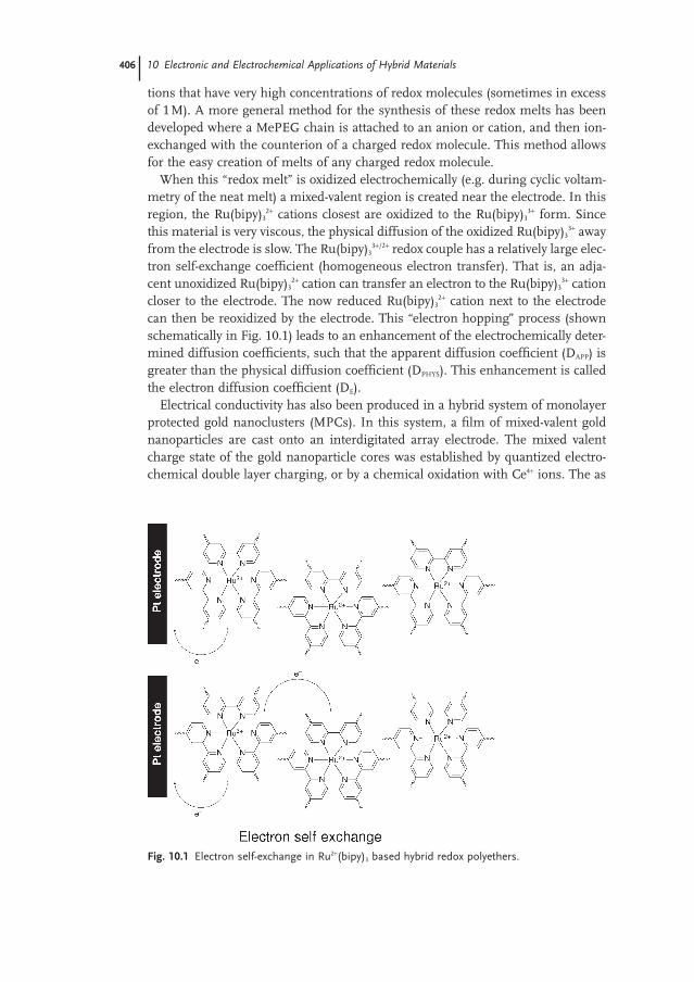
When this “redox melt” is oxidized electrochemically (e.g. during cyclic voltam-metry of the neat melt) a mixed-valent region is created near the electrode. In thisregion, the Ru(bipy)3
2+ cations closest are oxidized to the Ru(bipy)33+ form. Since
this material is very viscous, the physical diffusion of the oxidized Ru(bipy)33+ away
from the electrode is slow. The Ru(bipy)33+/2+ redox couple has a relatively large elec-
tron self-exchange coefficient (homogeneous electron transfer). That is, an adja-cent unoxidized Ru(bipy)3
2+ cation can transfer an electron to the Ru(bipy)33+ cation
closer to the electrode. The now reduced Ru(bipy)32+ cation next to the electrode
can then be reoxidized by the electrode. This “electron hopping” process (shownschematically in Fig. 10.1) leads to an enhancement of the electrochemically deter-mined diffusion coefficients, such that the apparent diffusion coefficient (DAPP) isgreater than the physical diffusion coefficient (DPHYS). This enhancement is calledthe electron diffusion coefficient (DE).
Electrical conductivity has also been produced in a hybrid system of monolayerprotected gold nanoclusters (MPCs). In this system, a film of mixed-valent goldnanoparticles are cast onto an interdigitated array electrode. The mixed valentcharge state of the gold nanoparticle cores was established by quantized electro-chemical double layer charging, or by a chemical oxidation with Ce4+ ions. The as
406 10 Electronic and Electrochemical Applications of Hybrid Materials
Fig. 10.1 Electron self-exchange in Ru2+(bipy)3 based hybrid redox polyethers.
synthesized Au nanoparticles have negative charges on the cores (likely from theBH4
− reductant), resulting in an open circuit potential of about −0.61V (vs.Ag/Ag+). The open circuit potential is measured as the potential difference be-tween the working electrode and a reference electrode, here the large negative val-ue indicates that the Au clusters have the potential to transfer their excess electronsto other species and is a measure of their effectiveness as a reducing agent. Theopen circuit potential can be adjusted to more positive values through exposure tothe Ce4+ oxidant. This oxidation of the Au cores allows the average charge state ofthe cores to be adjusted. Electrical conductivity results from an electron self-exchange reaction between adjacent Au nanoparticles in different charge states
Electron self-exchange reaction (1)
Furthermore, the conductivity is a function of mixed-valent charge state, such thata rest potential which corresponds to a single valent average charge state (e.g. −2,−1, 0, +1) has a lower conductivity than a sample with a rest potential correspond-ing to a mixed valent average charge state (e.g. −1.5, −0.5, +0.5). In this system an average charge state of −0.5 would correspond to a mixture of 50% negativelycharged MPC− and 50% neutral MPC0. The loss of electrical conductivity in singlevalent MPC films is because electron self-exchange is not possible when all thenanoclusters are in the same charge state (electron hopping in a single valent filmis not a self-exchange reaction, ∆G0 > 0).
Molecular conductors capable of switching on and off their conductivity basedon an external stimulus (such as light, temperature, and pressure) have been pre-pared from hybrid materials. These materials generally incorporate an organic rad-ical cation such as tetrathiafulvalene (TTF) or bis(ethylenedithio)tetrathiafulvalene(ET) complexed with an anion inorganic coordination complex. In one example,the charge-transfer salt ET4K[Fe(CN)5NO]2, which consists of a layered structure,displayed metallic electrical properties down to very low temperatures. The irra-diation of this material leads to a structural reorganization which allows for elec-tron localization in the conduction band leading to metallic-like conductivity underirradiation.
10.3.2Li+ Conductivity
Polymer electrolytes are frequently based on an organic macromolecule that is capable of dissolving inorganic salts of this ion of interest (i.e. PEO dissolvesLiPF6). In the poly(ethylene oxide) system, each ethylene oxide segment containsa Lewis basic oxygen atom which can coordinate to the Li+ cation. This formationof coordinative bonds between the polymer and the Li+ ion is critical to overcom-ing the lattice energy of the salt, because otherwise the salt will crystallize in thepolymer matrix which will lead to a dramatic loss of Li+ mobility. Since there is alimit to the energy released by the formation of these coordinative covalent bonds,inorganic salts with very strong lattice energies are unsuitable for polymer
MPC MPC MPC MPCkEX0 0+ ⎯ →⎯ ++ +
10.3 Fundamental Mechanisms of Conductivity in Hybrid Materials 407
electrolyte applications (e.g. LiF has too large a lattice energy to be dissolved inmost polymer systems). In addition, the use of very weakly coordinating anionssuch as PF6
− and TFSI−, (CF3SO2)2N−, tends to lower the lattice energy of the lithium salt, and serves to reduce ion-pairing in the electrolyte.
Poly(ethylene oxide) based materials, and the similar poly(ethylene glycol) materials, are known to conduct small cations through segmental motions of theethylene oxide units. Ionic conductivity in these types of polymer electrolytes occurs primarily in the amorphous phase of the polymer through these segmentalmotions of the polymer’s units. In order for the Li+ cation to move, these polymersegments have to reorganize to “hand off” the Li+ cation from one coordinationsite to another site. The rate of reorganization of the polymer segments is depen-dant on the glass transition temperature (Tg) of the material. The Tg is the tem-perature where an amorphous polymer transitions from a glassy state (polymersegments are “frozen” – immobile but not crystalline) to a rubbery state (polymersegments are free to move and rearrange).
The glass transition temperature is a measure of the freedom of the polymersegments to reorganize, and can be compared between different polymers. The Tg
of a polymer is strongly affected by the flexibility of the polymer backbone and thenature of the pendant groups. Siloxane and phosphazene polymers have very flex-ible backbones and generally have very low Tg values. Large bulky pendant groupsare more likely to become entangled and can raise the Tg of the polymer. How-ever, large pendant groups can also lower the Tg by increasing the separation between polymer chains creating “free volume” in which the polymer can moreeasily reorganize.
Electrolytes based on high molecular weight PEO frequently contain crystallineregions at room temperature that generally do not participate in ionic conduc-tivity which leads to a drop in the room temperature ionic conductivity (the conducting pathway has to go around these crystalline regions). One strategy tomaximize the ionic conductivity is to design polymers with large volume fractionsof amorphous regions within the polymer. The addition of inorganic componentsinto polymer electrolytes can substantially increase the volume fraction of amor-phous regions in polymer electrolytes, leading to electrolytes with potentially larger ionic conductivities. In this regard, the influence of inert oxide fillers on theconductivity of PEO-based lithium electrolytes has been explored. It was foundthat small amounts of added nanoscale fillers such as SiO2 and Al2O3 stabilizedthe amorphous phase of the PEO giving a completely amorphous polymer elec-trolyte. Addition of these nanoscale fillers to already amorphous polymer phasesdid not improve the conductivity. Thus, the addition of oxide fillers would only be expected to help a crystalline, or partially crystalline, electrolyte to become more amorphous. Since the lithium ion conduction occurs exclusively in the amor-phous regions, making the polymer more amorphous should increase the ionicconductivity.
While Li+ conducting polymer electrolyte systems based on poly(ethylene oxide),poly(acrylonitrile), poly(methyl methacrylate), and poly(vinylidene fluoride) have
408 10 Electronic and Electrochemical Applications of Hybrid Materials
been developed, very little work has been done on hybrid polymeric systems basedon polymers other than poly(ethylene oxide). This is likely due to the ease withwhich PEO and PEG based polymers can be synthetically modified. However,some recent work has explored hybrid systems composed of polyfluorosiliconepolymers reinforced with nanosized silica. The polyfluorosilicone polymer waschosen for its high chemical and thermal stability. These hybrid electrolytes couldbe swollen in the presence of conventional liquid lithium electrolytes to obtain agel polymer electrolyte. In addition, hybrids of poly(methyl methacrylate) and TiO2
particles swollen with ethylene carbonate and lithium perchlorate were studied asgel polymer electrolytes. Here, the addition of TiO2 particles to the gel electrolytesresulted in enhanced diffusion of cations, while the diffusion of carbonate solventmolecules remained constant.
10.3.3H+ Conductivity
There are two general mechanisms responsible for proton mobility in proton-conducting electrolytes: the vehicle mechanism (which relies on the physical trans-port of a vehicle to move protons) and the Grotthus mechanism (which involvesthe proton being handed-off from one hydrogen bonding site to another). TheGrotthus mechanism is superficially similar to Li+ conductivity in that it dependson a site-to-site hopping mechanism, while the vehicle mechanism depends onthe rate of physical diffusion of the vehicle. Vehicles are simply molecules that arecapable of forming a bond to the free proton and of freely diffusing. Under cer-tain conditions, species such as H3O+ and H3PO4 can serve as proton carrying vehicles.
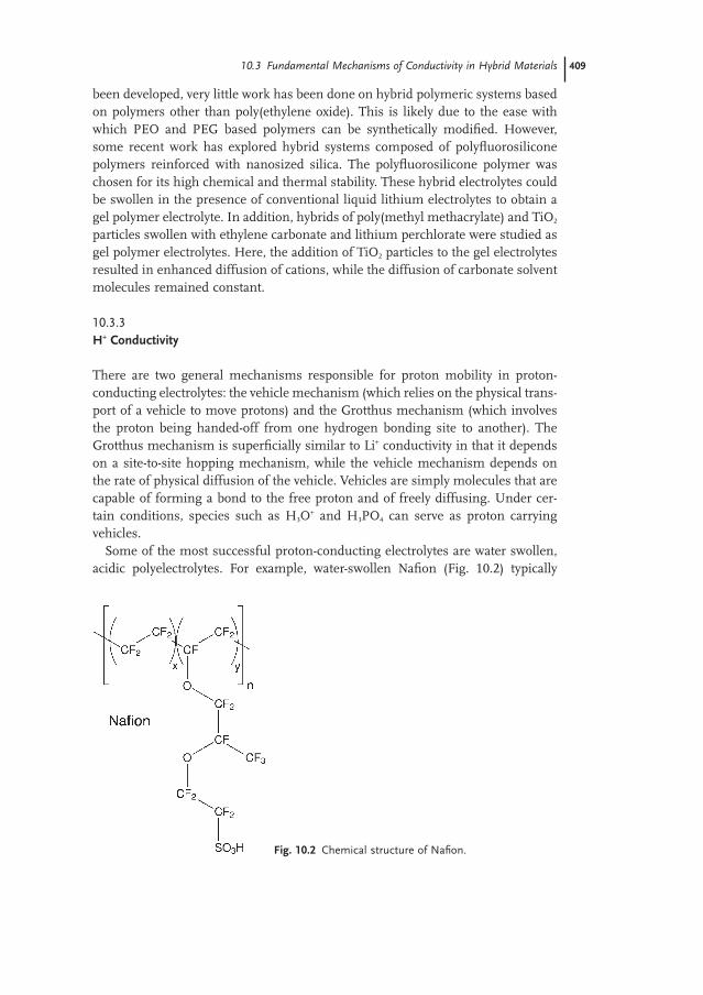
Some of the most successful proton-conducting electrolytes are water swollen,acidic polyelectrolytes. For example, water-swollen Nafion (Fig. 10.2) typically
10.3 Fundamental Mechanisms of Conductivity in Hybrid Materials 409
Fig. 10.2 Chemical structure of Nafion.
reaches a room temperature ionic conductivity of about 0.01S/cm. Nafion is a flu-oropolymer with pendant —SO3H groups. This polymer tends to aggregate to formnanoscale hydrophobic regions composed of the polymer backbone and nanoscalehydrophilic regions occupied by the pendant acid groups. Absorbed water migratesto the hydrophilic regions forming a continuous conducting pathway for the H+
ions. Thus, water is critical to the conductivity as proton mobility only occurs inthe water-swollen hydrophilic regions of the polymer. In these acidic polyelec-trolytes, the water molecules are likely protonated by the pendant acid groupsforming H3O+ ions. These materials are especially interesting for fuel cell appli-cations because the anions are covalently attached to the polymer backbone andtherefore immobile. The ionic conductivity of these materials essentially repre-sents pure H+ diffusion. Proton transport in these materials likely occurs througheither a physically diffusion of the H3O+ molecule (vehicle mechanism) or througha homogeneous H+ transfer to an adjacent hydrogen bonded water molecule (Grotthus mechanism).
In addition to Nafion, there are several other systems that have been explored as proton conducting membranes for PEM fuel cell applications. BallardAdvanced Materials Corporation has synthesized a proton-conducting membraneby sulfonating a copolymer primarily based on α,β,β,-trifluorostyrene. Here, theacidic —SO3H groups are introduced to the fluorinated polystyrene polymer after the polymerization step. Similarly, proton-conducting membranes have been prepared by sulfonation of poly(arylene ether)s such as poly(arylene ether ether ketone) (PEEK). These sulfonated poly(arylene ether)s have the potential advantages of wide availability, ease of processing, and chemical and thermal stability. Polymers based sulfonated poly(imide)s have also been used as proton-conducting electrolytes, unfortunately, these materials have a propensity to bequickly chemically degraded. Substituted polyphosphazenes, which are based on the [-P(R)2==N-]x backbone, have very flexible backbones, and have been employed as Li+ conducting electrolytes. Proton-conducting polyphosphazene polymers have been synthesized by attaching sulfonated aryl groups to the polymer backbone.
The one-way transport of H+ cations (from anode to cathode) in a fuel cell application can lead to the unfortunate problem of electro-osmotic drag of watermolecules. This motion of water molecules from the anode to the cathode alsocauses methanol to move at the same rate in a direct methanol fuel cell. This“cross-over” of fuel molecules can lead to a direct reaction between the methanolfuel and oxidizer at the cathode, which severely decreases the efficiency of the fuel cell.
In systems that display anhydrous proton conductivity, there are no water mol-ecules around to serve as vehicles for physical diffusion. These systems typicallyshow a large degree of Grotthus conductivity due to the hopping of the H+ ionsfrom one coordination site to another.
410 10 Electronic and Electrochemical Applications of Hybrid Materials
10.4Explanation of the Different Materials
10.4.1Sol–Gel Based Systems
Electrochemically-active hybrid materials have been prepared by covalently attaching redox-active groups to siloxane (or other inorganic) polymers. These are typically prepared through a condensation of a redox-active molecule contain-ing a —Si(OR)3 group to form a sol–gel network, or by hydrosilation of a vinyl-containing redox-active molecule to an inorganic polymer containing a Si—Hbonds. Strictly speaking, however, materials prepared by hydrosilation of Si—Hgroups are generally not considered sol–gel based materials. Since the redox-active groups are covalently immobilized on the inorganic polymer, and are immobile, charge transfer must occur through an electron hopping mechanism.In addition, the oxidation or reduction of these redox-active groups must be ac-companied by a diffusion of counterions into or out of the redox-active polymerin order to counteract the change in oxidation state. For example, the oxidation ofa vinylferrocene film (Fc0 to Fc+) must be accompanied by an influx of negativelycharged counterions to maintain charge neutrality. However, in electron conduct-ing systems, where electrons move through this hopping mechanism, the oxida-tion state of individual redox centers change, but the overall oxidation state of thefilm is unchanged. In this system no counterion flux is needed as there is nochange in to the overall oxidation state of the material. It turns out that the elec-trochemical properties of these polymer systems tend to be very dependant on thenature of the counterions and their ability to diffuse through the inorganic matrixin order to compensate for the charges created during redox cycling.
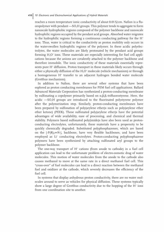
A similar class of redox active hybrids which are based on sol–gel synthesizedsilicates instead of siloxane polymers have also be prepared. These hybrid mate-rials can be referred to as hybrid redox silicates and have been formed by mixinga solution of a redox active molecule, such as quinone, with carbon particles anda silica sol, and allowing the mixture to gel into a carbon ceramic composite elec-trode (CCE) forming a class I hybrid. Class II redox active hybrids have also beensynthesized through sol–gel condensation of a trimethoxysilane-modified fer-rocene (i.e. Fc—Si(OMe)3) with TMOS (shown in Fig. 10.3).
In addition to redox active systems, the sol–gel synthesis of ion-conducting electrolytes shows considerable promise due to the easy processibility of sol–gelmaterials, especially for thin-film and chemically modified electrode applications.In this area, there has been considerable effort in the sol–gel synthesis of hybridH+- and Li+-conducting electrolytes for fuel cells and batteries. For example, classI Li+-conducting electrolytes have been synthesized by the addition of silica parti-cles to conventional Li+-conducting liquid electrolytes, such as ethylene and propy-lene carbonate based solvents. These composite electrolytes show a considerableincrease in the dimensional stability of the resulting electrolyte allowing for theconstruction of lithium battery cells with varied geometric designs. While, these
10.4 Explanation of the Different Materials 411
composite electrolytes offer advantages over all liquid electrolytes, they are still liquid mixtures which are susceptible to leakage and separation. Class II Li+
conducting electrolytes can be prepared by attaching oligomeric poly(ethylene) gly-col segments to alkoxysilanes, and then hydrolyzing the resulting PEG-modifiedsilanes and allowing the resulting material to condense into an organically modi-fied silicate (see Section 10.6.4). These class II materials are rubbery polymers, notviscous liquid gels, and are not susceptible to leakage problems. The design andsynthesis of new ion conducting polymer electrolyte materials is fast becoming alively area of research, with a few groups pursuing sol–gel based, hybrid inorganic–organic materials.
10.4.2Nanocomposites
One of the simplest hybrid materials with electrochemical applications is a dis-persion of conducting particles into a solid matrix, such as a gel, polymer, or in-organic solid. These systems typically show good electrical conductivity when theconcentration of the conductive particles exceeds the percolation threshold. Thisthreshold is reached when the particles are at a high enough concentration suchthat they can come into close enough contact with each other to create a networkof connected particles throughout solid matrix (section 3.1). These carbon–ceramiccomposite electrodes (CCEs see Fig. 10.4) materials can be synthesized from theincorporation of conductive particles of graphite into a solid silicate matrix form-ing a brittle but porous structure. Electrodes were synthesized by mixing carbonpowder with a silica sol and drawing the mixture into a glass capillary (the capil-lary serves to support the brittle material when dried). The mixture was then allowed to dry, and electrically contacted with silver paint. These composite
412 10 Electronic and Electrochemical Applications of Hybrid Materials
Fig. 10.3 A Class II redox-active silicate formed fromtrimethoxysilylferrocene and 1,1′-bis(trimethoxysilyl)ferrocenecopolymerized with tetramethoxysilane.
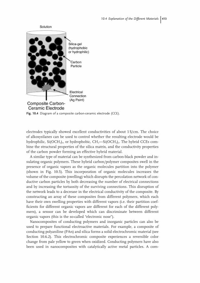
electrodes typically showed excellent conductivities of about 1S/cm. The choice of alkoxysilanes can be used to control whether the resulting electrode would behydrophilic, Si(OCH3)4, or hydrophobic, CH3—Si(OCH3)3. The hybrid CCEs com-bine the structural properties of the silica matrix, and the conductivity propertiesof the carbon powder forming an effective hybrid material.
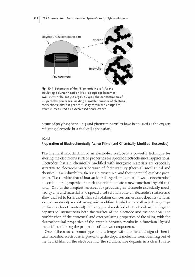
A similar type of material can be synthesized from carbon-black powder and in-sulating organic polymers. These hybrid carbon/polymer composites swell in thepresence of organic vapors as the organic molecules partition into the polymer(shown in Fig. 10.5). This incorporation of organic molecules increases the volume of the composite (swelling) which disrupts the percolation network of con-ductive carbon particles by both decreasing the number of electrical connectionsand by increasing the tortuosity of the surviving connections. This disruption ofthe network leads to a decrease in the electrical conductivity of the composite. Byconstructing an array of these composites from different polymers, which eachhave their own swelling properties with different vapors (i.e. their partition coef-ficients for different organic vapors are different for each of the different poly-mers), a sensor can be developed which can discriminate between differentorganic vapors (this is the so-called “electronic nose”).
Nanocomposites of conducting polymers and inorganic particles can also beused to prepare functional electroactive materials. For example, a composite ofconducting polyaniline (PAn) and silica forms a solid electrochromic material (seeSection 10.6.2). This electrochromic composite experiences a reversible colorchange from pale yellow to green when oxidized. Conducting polymers have alsobeen used in nanocomposites with catalytically active metal particles. A com-
10.4 Explanation of the Different Materials 413
Fig. 10.4 Diagram of a composite carbon-ceramic electrode (CCE).
posite of polythiophene (PT) and platinum particles have been used as the oxygenreducing electrode in a fuel cell application.
10.4.3Preparation of Electrochemically Active Films (and Chemically Modified Electrodes)
The chemical modification of an electrode’s surface is a powerful technique for altering the electrode’s surface properties for specific electrochemical applications.Electrodes that are chemically modified with inorganic materials are especially attractive to electrochemists because of their stability (thermal, mechanical andchemical), their durability, their rigid structures, and their potential catalytic prop-erties. The combination of inorganic and organic materials allows electrochemiststo combine the properties of each material to create a new functional hybrid ma-terial. One of the simplest methods for producing an electrode chemically modi-fied by a hybrid material is to spread a sol solution onto an electrode’s surface andallow that sol to form a gel. This sol solution can contain organic dopants (to forma class I material) or contain organic modifiers labeled with trialkoxysilane groups(to form a class II material). These types of modified electrodes allow the organicdopants to interact with both the surface of the electrode and the solution. Thecombination of the structural and encapsulating properties of the silica, with theelectrochemical properties of the organic dopants, results in a functional hybridmaterial combining the properties of the two components.
One of the most common types of challenges with the class I design of chemi-cally modified electrodes is preventing the dopant molecule from leaching out ofthe hybrid film on the electrode into the solution. The dopants in a class I mate-
414 10 Electronic and Electrochemical Applications of Hybrid Materials
Fig. 10.5 Schematic of the “Electronic Nose”. As theinsulating polymer / carbon black composite becomesswollen with the analyte organic vapor, the concentration ofCB particles decreases, yielding a smaller number of electricalconnections, and a higher tortuosity within the compositewhich is measured as a decreased conductance.
rial are retained in the silica film through simple physical entrapment. Here, theleaching of electroactive species from the silica film can be prevented by covalentlyattaching it to the silica, however this will severely limit the electroactive speciesmass transport within the film.
Electrocatalytic applications are a powerful demonstration of the advantages of chemically modified electrodes by preparing electrodes with tailored electro-chemical properties. In one example of a hybrid electrocatalytic application, zeo-lite films were attached to electrodes in order to selectively bind O2 gas near theelectrode for reduction. Frequently, electrocatalysis is slow at bare electrodes,meaning that a large overpotential is needed to achieve rapid redox chemistry. Inthis case, a mediator can speed up the electrode reaction by oxidizing the analyte,and becoming reduced in the process. The mediator can then be rapidly re-oxidized at the electrode surface, effectively mediating the oxidation of the analyte.With this mediation, the oxidation of the analyte occurs at the formal potential of the mediator. One example of this type of chemistry is the o-quinone mediatedoxidation of NADH at a carbon electrode. Here, o-quinone can be attached to a carbon electrode through either spontaneous adsorption of a monolayer film, orencapsulation in a polymer film. The immobilized o-quinone then oxidizes solu-tion-phase NADH (becoming reduced). The reduced o-quinone is then immedi-ately re-oxidized by the electrode.
10.5Special Analytical Techniques
The electrical and electrochemical properties of hybrid materials are typically char-acterized through electrochemical techniques designed to understand how ionsand electrons are transported in this material. In this section, a brief introductionto these special techniques will be given.
10.5.1Electrochemical Techniques
One of the most interesting parameters of a solid electrolyte is the total ionic con-ductivity and the fraction of that conductivity that is carried by each ion. In mostelectrolytes, ionic conductivity occurs through the motion of charged species (i.e.ionic mobility). The electrochemical measurement of ionic conductivity is difficultdue to the resistance to ion motion at the electrode’s surface (as compared to therelatively easy measurement of DC electrical conductivity in solids). In order toovercome this capacitance problem, a technique called ac-impedance spectroscopyis frequently used. In this measurement, the liquid (or semi-solid) electrolyte isplaced between two parallel electrodes (either in a special ionic conductivity cellor on an interdigitated array electrode), and a sinusoidal potential is applied between the electrodes. The current flow is monitored, and the phase differencebetween the applied potential and the resulting current is determined (shown in
10.5 Special Analytical Techniques 415
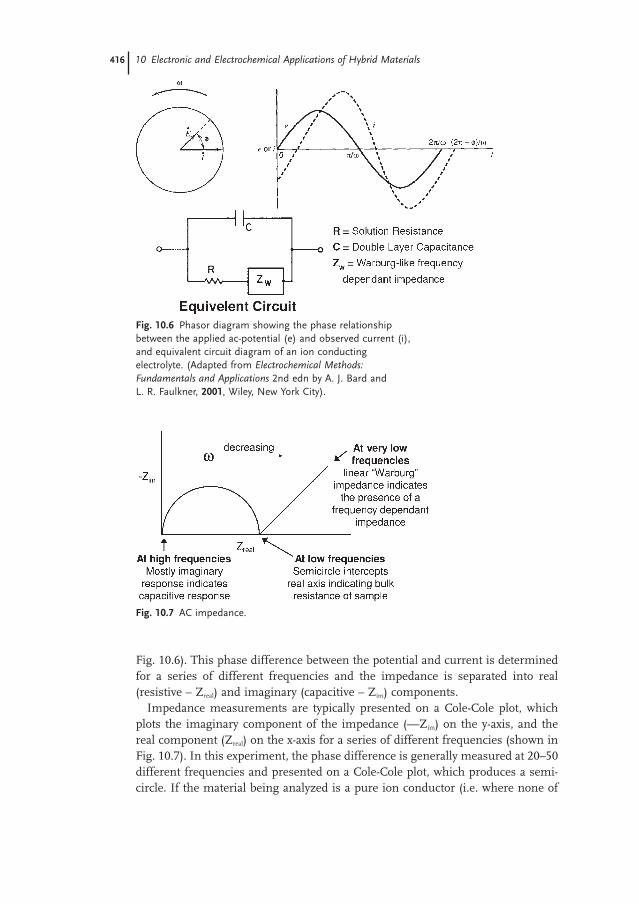
Fig. 10.6). This phase difference between the potential and current is determinedfor a series of different frequencies and the impedance is separated into real (resistive – Zreal) and imaginary (capacitive – Zim) components.
Impedance measurements are typically presented on a Cole-Cole plot, whichplots the imaginary component of the impedance (—Zim) on the y-axis, and thereal component (Zreal) on the x-axis for a series of different frequencies (shown inFig. 10.7). In this experiment, the phase difference is generally measured at 20–50different frequencies and presented on a Cole-Cole plot, which produces a semi-circle. If the material being analyzed is a pure ion conductor (i.e. where none of
416 10 Electronic and Electrochemical Applications of Hybrid Materials
Fig. 10.6 Phasor diagram showing the phase relationshipbetween the applied ac-potential (e) and observed current (i),and equivalent circuit diagram of an ion conductingelectrolyte. (Adapted from Electrochemical Methods:Fundamentals and Applications 2nd edn by A. J. Bard and L. R. Faulkner, 2001, Wiley, New York City).
Fig. 10.7 AC impedance.
the measured current is Faradaic current due to redox reactions) the low frequencyintercept with the x-axis equals the bulk resistance of the electrolyte. This resist-ance is then converted to the material specific (and geometry-independent) con-ductivity values using the calculated or measured cell constant of the impedanceelectrode.
While, ac-impedance measurements are very helpful at determining the totalionic conductivity, it is difficult to separate out the individual contributions of eachion. According to the Nernst-Einstein equation (2), the total conductivity (σION) isequal to the sum of the contributions from the individual ions (in this case an anion and a cation).
Nernst-Einstein equation (2)
In the Nernst-Einstein equation, the contribution to the overall ionic conductivityfrom each ion is the product of the ion’s charge squared (z2), the ion’s diffusioncoefficient (D), and the concentration (C) of each ion. Since, the total ionic con-ductivity is a sum of contributions from all the ions present, the contributionsfrom each of the ions must sum to give the total conductivity. Another way to de-scribe this is to say that the sum of the fractions of charge carried by the individ-ual ions (the transference numbers: t+ and t−) must be equal to unity (equation 3).
(3)
The fraction of charge carried by any one ion (ti) can be described as the ratio ofthat ion’s contribution to conductivity to the sum of the contributions from all theions (equation 4).
Transference Number (4)
In order to calculate the fraction of charge carried by a specific ion (i.e. the trans-ference number ti), you first need to be able to measure the diffusion coefficientfor that specific ion. With the diffusion coefficient of one of the ions, and the ac-impedance measured total ionic conductivity (σ), you can then solve for the dif-fusion coefficient of the other ion through the Nernst-Einstein equation. For example, transference numbers have been calculated through electrochemicalmeasurements of polyether-tailed Co(bipy)3
2+ hybrid molten salts. In this system,both the ionic conductivity of the melt, and the electrochemical diffusion of theCo(bipy)3
2+ cation can be measured electrochemically. These values can then beused to calculate the diffusion coefficient of the ClO4
− anions, and then determinethe transference number of each of the ionic species.
The measurement of electrical conductivity in hybrid materials is somewhatsimpler than the measurement of ionic conductivity because the electrical con-ductivity does not suffer the same large resistances at the electrode interface as
tz DC
z D Ci
i i i
j j j j
=∑
2
2
t t+ −+ = 1
s ION = +( )+ + + − − −F
RTz D C z D C
22 2
10.5 Special Analytical Techniques 417
ionic conductivities. Electrical conductivities are typically measured using the di-rect current technique of four-point probe resistivity. This technique has the strongadvantage of automatically canceling out the contact resistances that are due to thefrequently large impedances at the interfaces between the probes and the mate-rial. Four-point probe measurements are capable of quickly and effectively meas-uring a geometry independent, material-property specific resistivity value (whichis easily converted to conductivity). The key to the four point probe technique isthat current and voltage are delivered and sensed on separate electrodes (twoprobes deliver current, while the other two probes sense voltage). This techniqueis especially useful for solid samples, but is difficult to apply to liquids where thepresence of double layer capacitances greatly complicate the interpretation of theresistivity data.
10.5.2Pulsed Field Gradient NMR
Nuclear magnetic resonance techniques have recently been developed that are capable of measuring the self-diffusion of NMR-active nuclei. The basic experi-ment for this measurement is called the Pulsed Gradient Spin-Echo (PGSE) ex-periment. In this experiment, an initial pulsed-field gradient pulse phase-encodesthe nuclear spins according to their physical position along the z-axis (the inten-sity of the pulse varies along the z-axis gradient). After a period of delay time, asecond pulsed-field gradient pulse is applied which is exactly opposite to the firstpulse. If the nuclei have not translated (e.g. diffused) during the delay, then thesecond pulse exactly undoes the encoding from the first pulse, and the obtainedNMR signal is just as if there had been no initial pulses. However, if the nucleihave moved, the second gradient pulse does not exactly reverse the first pulse, andthe resulting NMR signal is attenuated. This loss of intensity can be described byan equation in terms of the diffusion coefficient of the nuclei. Typically, a seriesof different delays are employed, and the resulting data is fit to extract the self-diffusion coefficient.
Pulsed field gradient NMR techniques have been used to directly measure thediffusion coefficients of Li+ cations and fluorine containing anions to determinemobilities and transference numbers in lithium-conducting polymer electrolytes.This technique works well for systems that contain NMR active nuclei, which haveNMR signals that are clear of interferences. For example, 7Li is a NMR active nuclei, and in most lithium conducting polymer electrolytes, the mobile Li+ ions’signal is uncomplicated by the presence of any other chemical forms of lithium inthe electrolyte. These pfg-NMR measurements can be made using both solid-stateor conventional liquid NMR instruments and produce very reliable diffusion data.
In one example of this type of measurement, pulsed field gradient NMR (pfg-NMR) measurements (section 5.2) were used to directly measure the ion-transport properties in a of composite electrolyte composed of poly(ethylene glycol)dimethyl ether, and hydrophobic fumed silica doped with Li(CF3SO2)2N (LiTFSI).In this experiment, ion diffusion coefficients could be determined by measuring
418 10 Electronic and Electrochemical Applications of Hybrid Materials
the Li+ cation and the fluorine in the TFSI− anion. By directly measuring the dif-fusion coefficients of both anions and cations, the transference numbers for theions could be calculated.
10.6Applications
10.6.1Electrochemical Sensors
Carbon-ceramic composite electrodes (CCEs) have been designed and synthesizedas reference electrodes and for electrocatalytic applications. As described above,these electrodes were synthesized by mixing carbon powder with a silica sol. Elec-trodes containing only carbon particles in the silica gel can be used as “normal”indicating electrodes. When a hydrophilic silica precursor such as tetramethy-lorthosilicate (TMOS, Si(OCH3)4), is used, the hybrid composite of carbon parti-cles in silica is hydrophilic, allowing an aqueous solution to permeate into theCCE. This leads to a very large effective surface area of the electrode as a largenumber of carbon particles are in contact with the solution. However, if a hydrophobic silica precursor such as methyltrimethoxysilane, CH3—Si(OCH3)3, isused, the surface of the composite is hydrophobic, leaving only the carbon parti-cles on the outer interface in contact with the solution. This leads to a small ef-fective surface area as only the carbon particles on the surface are in contact withthe solution. Fortunately though, this hydrophobic material acts as an array of microelectrodes as the carbon particles are dispersed, and on average are far from each other. This type of electrode geometry can be very favorable for generalelectrochemical applications.
This CCE chemistry can also be extended to prepare biosensing electrode assemblies. The bioactive hybrid electrode containing glucose oxidase was pre-pared by the entrapment of this enzyme in the above describe CCE geometry. Thisfilm was cast upon a glassy carbon electrode and dried (shown schematically inFig. 10.8). In the case of a liquid sensor, the electrode design must allow for fastequilibration with the analyte solution. Here, the large surface area film on theglassy carbon electrode allows for fast mass transport between the solution andthe composite film on the electrode’s surface. The modified electrode can then beplaced into an analyte solution. Upon addition of glucose, the hydrogen peroxideproducts of the electrochemical oxidation of glucose to gluconolactone can be de-tected electrochemically in the hybrid electrode.
While graphite typically exhibits poor electrocatalytic activity, the addition ofelectrocatalytically active dopants, to form a modified CCE electrode, shows elec-trocatalytic activity. The addition of cobalt tetramethyoxymesoporphyrin (TMMP)to a CCE allows this composite electrode to anodically detect SO2, and cathodical-ly detect CO2 and O2. In this configuration (shown schematically in Fig. 10.8), theCo-TMMP serves as the electrocatalyst and the carbon particles are the conductive
10.6 Applications 419
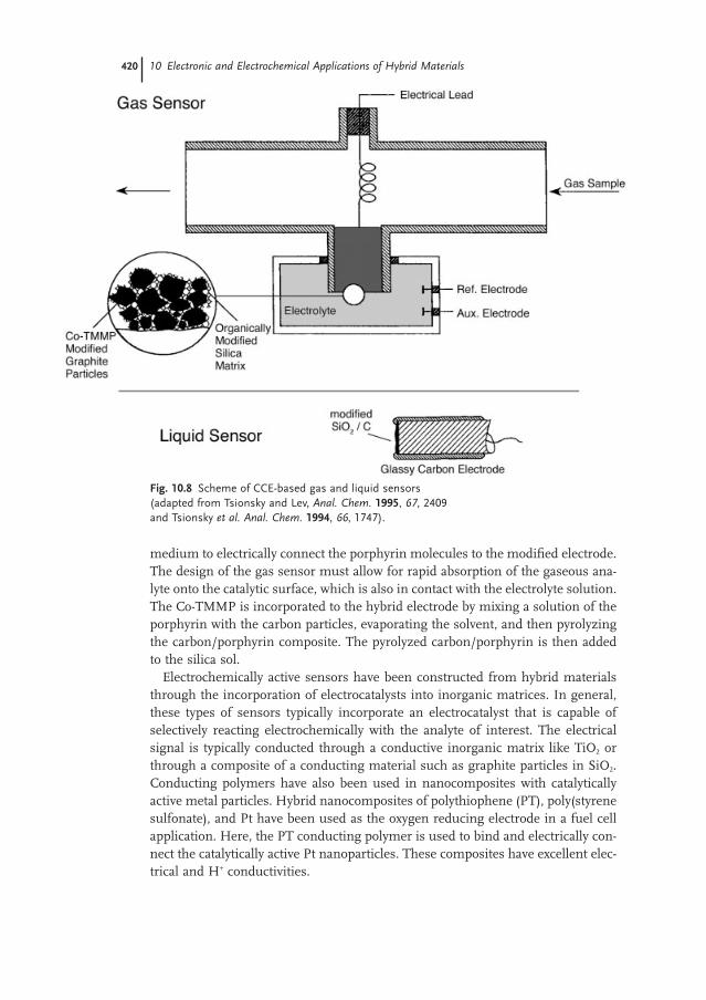
medium to electrically connect the porphyrin molecules to the modified electrode.The design of the gas sensor must allow for rapid absorption of the gaseous ana-lyte onto the catalytic surface, which is also in contact with the electrolyte solution.The Co-TMMP is incorporated to the hybrid electrode by mixing a solution of theporphyrin with the carbon particles, evaporating the solvent, and then pyrolyzingthe carbon/porphyrin composite. The pyrolyzed carbon/porphyrin is then addedto the silica sol.
Electrochemically active sensors have been constructed from hybrid materialsthrough the incorporation of electrocatalysts into inorganic matrices. In general,these types of sensors typically incorporate an electrocatalyst that is capable of selectively reacting electrochemically with the analyte of interest. The electricalsignal is typically conducted through a conductive inorganic matrix like TiO2 orthrough a composite of a conducting material such as graphite particles in SiO2.Conducting polymers have also been used in nanocomposites with catalytically active metal particles. Hybrid nanocomposites of polythiophene (PT), poly(styrenesulfonate), and Pt have been used as the oxygen reducing electrode in a fuel cellapplication. Here, the PT conducting polymer is used to bind and electrically con-nect the catalytically active Pt nanoparticles. These composites have excellent elec-trical and H+ conductivities.
420 10 Electronic and Electrochemical Applications of Hybrid Materials
Fig. 10.8 Scheme of CCE-based gas and liquid sensors(adapted from Tsionsky and Lev, Anal. Chem. 1995, 67, 2409and Tsionsky et al. Anal. Chem. 1994, 66, 1747).
The electrochemical reduction of Fe3+/2+ in a room-temperature melt of irontetraphenylporphyrin with four covalently attached short poly(ethylene glycol)chains can be used to sense the presence of volatile Lewis bases such as pyridine.This iron porphyrin has an open axial coordination site and coordination of a Lewisbase at this axial site causes a shift in the electrochemical reduction potential of the Fe3+ porphyrin. The presence of a Lewis base can be detected by applying apotential of 0V which is not sufficient to reduce the uncoordinated Fe3+, but is sufficient to reduce the base-coordinated Fe3+. In this experiment, the flow of current would indicate the coordination of a Lewis basic gas molecule. This ma-terial has been shown to be an effective and selective detector in a gas chromato-graphic application for Lewis basic molecules, and is minimally responsive toanalytes that do not coordinate to the Fe porphyrin.
Hybrid materials can also be adapted to ion-selective applications through theformation of hybrid materials doped with ionophores. Typically, these materialsconsist of an ionophore immobilized within a porous ceramic matrix. In one example, a composite silicate was synthesized containing a covalently attachedsmall 12-crown-4 ether and a tetraphenyl borate anion in order to sense K+ andNa+ ions. The incorporation of these ions into the film was used to generate a field-effect transistor effect. Effective ionophores are typically bulky species which areimmobilized in porous supports with sufficient pore size to allow the influx of ionic species.
10.6.2Optoelectronic Applications
Electrogenerated chemiluminescence (ECL = the generation of light from electro-chemically produced chemical species) has been created in hybrid composites ofswollen silica gels containing the Ru(bipy)3
3+ ion and the reductant tripropylamine(TPA). The ECL emission arises from the injection of an electron into a ligand-based excited state on the Ru(bipy)3
3+. This electron can then fall down in energyinto a metal-based orbital releasing a photon of light (the ECL). In this system, theECL is generated by either a direct electrochemical reduction of Ru(bipy)3
3+ or bya reaction of Ru(bipy)3
3+ with the TPA radical. The silica gel serves to establish amicroscopically rigid structure that cuts down (but does not eliminate) diffusionof the Ru(bipy)3
3+ and TPA species. This hybrid system has shown a significant in-crease in the stability of the ECL which is likely due to the rigidity of the systemprovided by the silica gel.
Electrogenerated chemiluminescence has also been generated in a system com-posed of a redox polyether melt of Ru(bipy)3
2+. In this system, two short poly(eth-ylene glycol) chains are attached to a Ru(bipy)3
2+ cation making the perchlorate saltinto a room temperature viscous molten salt (only two PEG chains were attachedin order to increase the Tg of the resulting hybrid). This material was then placedon an interdigitated array, and a voltage of 2.4V was applied. This voltage is suf-ficient to oxidize Ru(bipy)3
2+ at the anode and reduce it at the cathode forming con-centration gradients of the 3+ ion at the anode, and the 1+ ion at the cathode.
10.6 Applications 421
These concentration gradients expand into the bulk solution until they meet some-where near the midpoint between the two electrodes. In this system, an interdig-itated array electrode is used to minimize the distance between electrodes, andgive an open geometry that is conducive to detecting luminescence between theelectrodes. When the concentration gradients meet, the reduced Ru(bipy)3
+ trans-fers an electron to the oxidized Ru(bipy)3
3+ species which up accepting the electronforms the excited Ru(bipy)3
2+* state, which decays to ground state Ru(bipy)32+ by
emitting a photon. Since this material was designed to have a low Tg, the authorswere able to “freeze” the established concentration gradients by simply loweringthe temperature below the material’s Tg of −5°C. The frozen film retained its abil-ity to generate ECL, showed diode-like rectification, and even responded rapidlyto applied voltages.
Dye-sensitized solar cells show great promise for solar energy conversion. Inthis system, an electronically conducting, mesoporous semiconducting anode (typ-ically TiO2) is modified by an adsorbed layer of photosensitizing dye molecules.Photoexcitation of the dye molecule results in the injection of an electron into theconduction band of the TiO2. This electron then moves through an external cir-cuit to the cathode. The photooxidized dye molecule is reduced by a species in theelectrolyte (typically the I−/I3
− redox system). In this case, 3I− are oxidized to I3−
which diffuses to the cathode. At the cathode, I3− is reduced by the photoexcited
electrons that have traveled through an external circuit. The voltage generated un-der illumination corresponds to the difference between the Fermi level of the elec-tron in the solid and the redox potential of the solution redox couple. Overall,electricity is generated without permanent chemical transformation. In addition,this system has been constructed using a hybrid gel electrolyte composed of fumedsilica and the organic ionic liquid, 1-methyl-3-propylimidazolium iodide. In thiselectrolyte, the silica particles serve to solidify the ionic liquid electrolyte. Thissemi-solid electrolyte may enable the fabrication of flexible, solid-state devices freeof leakage and available in varied geometries.
Electrochromic Materials can also be prepared from hybrid materials. For example, a composite PAn, PMMA, and silica can be synthesized by the hydroly-sis of TEOS in a solution containing the preformed PAn and PMMA polymers.This electrochromic composite is then brushed onto a transparent conductor suchas indium-doped tin oxide (ITO). When the PAn conducting polymer containingcomposite is oxidized, a reversible color change from pale yellow to green is ob-served. The incorporation of the conducting polymer into the composite showssimilar electrochemistry to that of an electrochemically synthesized film of PAnon an electrode. In addition, the incorporation of PAn into the composite greatlyincreases the adhesion of the film to the electrode by preventing the oxidized formof PAn from dissolving from the surface of the electrode.
The incorporation of WO3 particles into a PAn film offers the opportunity to access the clear to dark blue color change of WO3 when reduced. In this device,alternating layers of WO3 and PAn were electrodeposited onto a transparent con-ductor. This multilayer composite film can then be reduced forming the dark blueform of the WO3, and then oxidized changing the WO3 layer back to colorless and
422 10 Electronic and Electrochemical Applications of Hybrid Materials
changing the PAn layer to green. Thus, this device represents and electrochromicwindow that can change color between dark blue and green.
10.6.3H+-conducting Electrolytes for Fuel Cell Applications
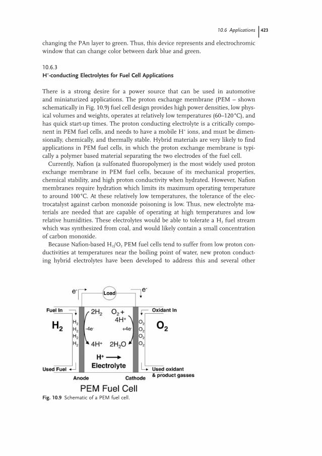
There is a strong desire for a power source that can be used in automotive and miniaturized applications. The proton exchange membrane (PEM – shownschematically in Fig. 10.9) fuel cell design provides high power densities, low phys-ical volumes and weights, operates at relatively low temperatures (60–120°C), andhas quick start-up times. The proton conducting electrolyte is a critically compo-nent in PEM fuel cells, and needs to have a mobile H+ ions, and must be dimen-sionally, chemically, and thermally stable. Hybrid materials are very likely to findapplications in PEM fuel cells, in which the proton exchange membrane is typi-cally a polymer based material separating the two electrodes of the fuel cell.
Currently, Nafion (a sulfonated fluoropolymer) is the most widely used protonexchange membrane in PEM fuel cells, because of its mechanical properties,chemical stability, and high proton conductivity when hydrated. However, Nafionmembranes require hydration which limits its maximum operating temperatureto around 100°C. At these relatively low temperatures, the tolerance of the elec-trocatalyst against carbon monoxide poisoning is low. Thus, new electrolyte ma-terials are needed that are capable of operating at high temperatures and lowrelative humidities. These electrolytes would be able to tolerate a H2 fuel streamwhich was synthesized from coal, and would likely contain a small concentrationof carbon monoxide.
Because Nafion-based H2/O2 PEM fuel cells tend to suffer from low proton con-ductivities at temperatures near the boiling point of water, new proton conduct-ing hybrid electrolytes have been developed to address this and several other
10.6 Applications 423
Fig. 10.9 Schematic of a PEM fuel cell.
shortcomings of current polymer electrolytes. In one general example of thischemistry, inorganic components have been employed to improve the self-humidification of the membrane (especially at the anode) by incorporating a hydrophilic inorganic oxide into the membrane that serves to attract and retainwater. In addition, these inorganic components can also contain a catalyst that promotes the reaction between dissolved oxygen and the fuel in order to stop thefuel from crossing over in direct methanol fuel cell applications. Furthermore, this self-humidification application has been extended to use solid oxide proton conductors as the inorganic oxide component in order to both retain water and to increase proton conductivity by offering an addition proton conducting path.Inorganic materials can also be incorporated into proton conducting membranesto improve the thermal and mechanical stability of composite membranes with-out losing ionic conductivity.
This strategy has been employed to create advanced H+-conducting hybridsbased on Nafion and silica or titania that are capable of self-humidification. Specif-ically, a silica or titania sol was added to a solution of Nafion, then cast and driedto form the hybrid polymer electrolyte membrane. Platinum nanoparticles, in theform of Pt(NH3)4Cl2, were also added to the hybrid membrane. The membranewas then capable of self-humidifying when any H2 fuel crossed over and reactedwith O2 at the Pt nanoparticles. The product of this reaction is water, which canthen be absorbed by the hygroscopic silica or titania particles. The addition of theinorganic components into this membrane allows for a thinner electrolyte, whichincreases the performance of the fuel cell.
In addition to self-humidification, the addition of oxide materials to proton con-ducting membrane has been explored for high-temperature operations in order to allow the composite electrolyte to remain hydrated at temperatures near orabove the boiling point of water. Here, a sol–gel technique has been used to addnanoscale silica particles into a PFSA membrane. The silica particles must be verysmall such that they can enter the conducting channels of the Nafion membranesand increase the water uptake of the electrolyte composite. This strategy was testedin a H2/O2 proton exchange membrane (PEM) fuel cell where it was determinedthat the presence of ~10% by weight of the nanoscale silica improved the waterretention of the electrolytes, which served to increase the proton conductivity athigh temperatures. Furthermore, the PEM fuel cell equipped with the compositeelectrolyte was able to provide four times the current density as a fuel cell with anunmodified Nafion at 130 °C and 3atm of pressure.
While in the previous example, the nanoscale silica particles were only there toimprove the water retention, other examples of the use of bi-functional additives,where the added component serves both water management and proton conduc-tion duties, has been described. Typically, these composite materials take advan-tage of the ability of certain solid oxide proton conductors to transport protons athigh temperatures, while using their oxide particle nature to improve water man-agement. In one example, zirconium phosphate, a solid inorganic proton con-ductor at high temperatures, was incorporated into a Nafion film. Here, zirconiumphosphate particles were formed inside the Nafion membrane by impregnated the
424 10 Electronic and Electrochemical Applications of Hybrid Materials
membrane with zirconyl chloride and phosphoric acid. The resulting hybridshowed an approximately four fold increase in current density (at 130 °C and 3bars of pressure) over unmodified Nafion membranes. In another example, sili-cotungstic acid (SiWA – also an inorganic solid proton conductor) was incorpo-rated into Nafion membranes. The water uptake (~2x) and ionic conductivity (~8x)of the silicotungstic acid/nafion-117 composite membrane were both significantlybetter than plain nafion-117 membranes. In addition, the mechanical and chem-ical stability of the composite membranes were as good as plain Nafion.
The addition of particles of solid proton conductors to a Nafion membrane assist proton conduction because they provide the water another pathway for con-duction within or on the surface of the added particle. In addition, the added particles are hydrophilic and provide addition hydrogen bonding sites. The for-mation of hydrogen bonds between the water and the added inorganic particleserves to slow down the evaporation of water and maintain the membrane’s hydration. This ability of the added particles to slow evaporation allows the mem-brane to operate at higher temperatures where water would normally evaporatefrom the membrane.
In addition to the above described class I hybrid composites, class II hybridscontaining strong covalent bonds between the organic and inorganic components,have also found applications in fuel cells. A class II, H+-conducting hybrid elec-trolyte has been synthesized by the sol–gel condensation of a species containingsulfonic and sulfonamide functionalized trialkoxysilanes. In this hybrid material,the sulfonamide groups are basic (i.e. H+ acceptors), and provide a site for the proton to “hop” to (the H+ hops from the sulfonate donor site to the sulfonamideacceptor site). The incorporation of both donor and acceptor sites facilitates thehopping mechanism of proton transport in this material leading to faster trans-port and higher ionic conductivities.
One of the first class II, H+-conducting hybrid materials was a silicate materialmodified with a trialkoxysilane-modified alkylamine, NH2—R—Si(OR)3. Theamine group acts as a base and becomes protonated in the presence of added acid.The acid loading is kept at less than 50% of the available amine groups in orderto leave a significant fraction of amine groups unprotonated. This is the key, because in order to allow for a Grotthus-type proton conductivity, there must beacceptor sites available for the H+ ion to hop into. This hybrid proton conductingelectrolyte, called an “aminosil”, is hard and nonporous when dried and shows aliquid-like conductivity of 10−5 Scm−1 at room temperature. In another example, anhydrous proton conducting electrolytes consisting of a hybrid PEG/silicate polymer have been prepared through sol–gel chemistry. When this material is rigorously dried, a hopping mechanism that depends on the volume fraction ofPEG in the polymer is responsible for transporting the H+ cations from one PEGcoordination site to another.
While a large concentration of sulfonate groups in the proton conducting mem-brane is desirable for high conductivity (more charge carriers gives greater con-ductivity), the addition of an excessive amount of sulfonate groups to a polymerelectrolyte may be accompanied by too much swelling, potentially leading to a
10.6 Applications 425
water soluble polymer. Too much swelling leads to a loss of mechanical strengthof the electrolyte membrane. However, the introduction of an inorganic compo-nent into the polymer electrolyte can compensate for the loss of mechanical stability. This strategy has been employed to create hybrid proton conducting electrolytes by attaching the acidic sulfonate group to the organic component after forming a hybrid gel. In an example of this type of chemistry, a mixture ofbenzotrialkoxysilane and an organotrialkoxysilane were hydrolyzed and allowed to gel forming an organic–inorganic hybrid. The phenyl component can then besulfonated, adding pendant and acidic —SO3H groups to the phenyl groups. Theresulting hybrid material showed an excellent room temperature conductivity of10−2 Scm−1and a thermal stability up to 250°C.
10.6.4Li+-conducting Electrolytes for Battery Applications
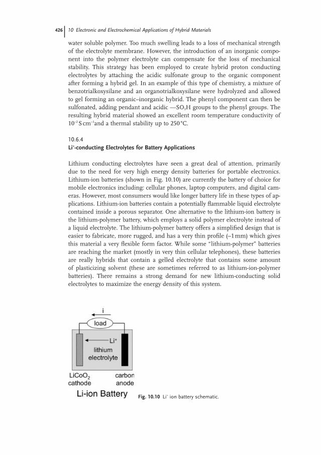
Lithium conducting electrolytes have seen a great deal of attention, primarily due to the need for very high energy density batteries for portable electronics. Lithium-ion batteries (shown in Fig. 10.10) are currently the battery of choice formobile electronics including: cellular phones, laptop computers, and digital cam-eras. However, most consumers would like longer battery life in these types of ap-plications. Lithium-ion batteries contain a potentially flammable liquid electrolytecontained inside a porous separator. One alternative to the lithium-ion battery isthe lithium-polymer battery, which employs a solid polymer electrolyte instead ofa liquid electrolyte. The lithium-polymer battery offers a simplified design that iseasier to fabricate, more rugged, and has a very thin profile (~1mm) which givesthis material a very flexible form factor. While some “lithium-polymer” batteriesare reaching the market (mostly in very thin cellular telephones), these batteriesare really hybrids that contain a gelled electrolyte that contains some amount of plasticizing solvent (these are sometimes referred to as lithium-ion-polymer batteries). There remains a strong demand for new lithium-conducting solid electrolytes to maximize the energy density of this system.
426 10 Electronic and Electrochemical Applications of Hybrid Materials
Fig. 10.10 Li+ ion battery schematic.
One general route to making class I hybrids for electrolyte applications is to im-mobilizing a liquid electrolyte in a solid-state matrix (this would be structurallyanalogous to what is currently being called a lithium polymer battery). This hasbeen accomplished by adding a silica sol to a solution of LiBF4 in ethylene car-bonate and propylene carbonate. The mixture of the silica sol and liquid electrolytewas allowed to gel, forming a dimensionally stable, semi-solid hybrid materialwhich maintains a substantial Li+ conductivity. The addition of the inorganic silicato this otherwise conventional liquid electrolyte adds mechanical stability, whilemaintaining a large room temperature ionic conductivity (~ 4× 10⁻³ Scm−1). In addition, thermal gravimetric analysis shows that this material is thermally stableup to 90 °C, and that the thermal stability is limited by the liquid EC/PC electrolyte.Thus, this material may have applications as a lithium-ion-polymer battery elec-trolyte as it could easily be cast into very flexible geometries.
In another example of this type of material, a composite electrolyte was preparedfrom a mixture of low molecular weight poly(ethylene glycol), LiClO4, and Al2O3
and SiO2 particles. The authors note an increase in the ionic conductivity in thismaterial over mixtures of LiClO4 in poly(ethylene glycol). Interestingly, the formation of ion pairs was examined by FT-IR spectroscopy and determined to bedecreased in the Al2O3 and SiO2 composites over the noncomposite materials.
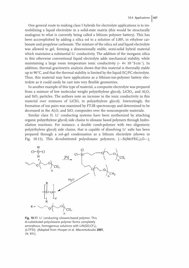
Similar class II, Li+ conducting systems have been synthesized by attaching organic poly(ethylene glycol) side chains to siloxane based polymers through hydro-silation reactions. For instance, a double comb-polymer with two oligomericpoly(ethylene glycol) side chains, that is capable of dissolving Li+ salts has beenprepared through a sol–gel condensation as a lithium electrolyte (shown in Fig. 10.11). This di-substituted polysiloxane polymers, [—Si(MePEGn)2O—]x
10.6 Applications 427
Fig. 10.11 Li+ conducting siloxane-based polymer. This di-substituted polysiloxane polymer forms completelyamorphous, homogenous solutions with LiN(SO2CF3)2
(LiTFSI). (Adapted from Hooper et al. Macromolecules 2001,34, 931).
(where MePEGn = —(CH2)3O(CH2CH2O)nCH3), formed completely amorphous,homogenous solutions with LiN(SO2CF3)2 (LiTFSI). The ionic conductivity reacheda room temperature peak of ~ 5× 10⁻⁴ Scm−1 with MePEG6 side chains (i.e. the sidechains were 6 ethylene oxide repeat units long). Unfortunately the dimensionalstability of these materials is fairly poor (they are viscous liquids that flow at roomtemperature). However, a method was developed for cross-linking a similar material to form a free-standing polymer with greater dimensional stability.
Siloxane-based polymers have also been prepared with a mixture of poly(ethylene glycol) side chains, and a second side chain containing a covalently attached anion. These materials have been prepared with trifluoromethylsulfon-amide (—NSO2CF3) anions, and sulfonate terminated perfluoroethers. These poly-electrolyte materials are rather unique, because the weakly interacting anions arecovalently linked to the polymer’s backbone. In polysiloxane-based hybrid materi-als, the siloxane polymer backbone adds a significant amount of flexibility to thehybrid which serves to decrease the glass transition temperature (Tg) and increasethe frequency of segmental motions of the polymer, which leads to increased ionicconductivity. Furthermore, the low energy barrier to rotation about the Si—O bondin siloxane polymers (~0.8kJmol−1) contributes a substantial amount of free vol-ume to the resulting polymer, which serves to further increase the rate of polymerreorganization, and consequently, ionic conductivity.
The applications for polyethylene oxide (PEO) based lithium conducting poly-mer electrolytes are limited by the inability to achieve both large ionic conductiv-ities and mechanical stability at temperatures below 70 °C. Addressing one of theseshortcomings tends to degrade the performance in the second area. For instance,the addition of a plasticizer can increase the ionic conductivity of a PEO-basedelectrolyte, but generally tends to dramatically decrease the mechanical stability.This problem has been addressed by creating hybrid composites of low molecu-lar weight, end-capped PEO, a lithium salt, and nanoscale surface-modified fumedsilica. This hybrid composite is a semi-solid material which displays room tem-perature ionic conductivities in excess of 10−3 Scm−1. Here, the surface modifica-tion of the nanoscale fumed silica particles is critical to the formation of an opennetwork structure that can increase the mechanical stability of the composite elec-trolyte. The surface modifying groups need to make the surface of the silica par-ticles somewhat incompatible with the polar PEO, so that they will associate withother silica particles to form the network. This very polar network then increasesthe mechanical stability of the electrolyte without decreasing the high conduc-tivity and Li+ transport gained from using the low molecular weight PEO.
Hybrid nanocomposites of conducting polymers and inorganic solids have beenprepared and utilized as high energy density electrode materials in Li+ ion batteryapplications. For example, composites of polyaniline (PAn) and V2O5 have beencombined to form a redox-active composite with Li+ acting as the primary ionicparticipant in the charge/discharge reactions. Here, the organic conducting poly-mer serves as both a electrical conductor to cycle the oxidation state of the V2O5 toLixV2O5. As the polymer is oxidized, the Li+ ions diffuse out of the composite asthe V2O5’s negative charges compensate the positive charges on the PAn.
428 10 Electronic and Electrochemical Applications of Hybrid Materials
10.6.5Other Ion Conducting Systems
Mixed ionic/electronic conductors have been synthesized from a hybrid nanocom-posite xerogel of V2O5 and poly(ethylene oxide). This material is synthesized by addition of an aqueous solution of PEO and lithium triflate to a vanadia sol. Thesolution was then evaporated to form a thin, flexible film. The addition of the PEOcomponent increased the spacing between the V2O5 layers. In order to determinethe relative contributions of electronic and ionic conductivity in this material, theauthors measured both the electrical conductivity by a four-point probe method,and ionic conductivity by AC-impedance methods. This composite material showshigh electronic conductivity through the V2O5 regions parallel to the film, as ex-pected. In addition, a lower ionic conductivity was measured perpendicular to thecomposite film. While the total ionic conductivity was substantially lower than theelectrical conductivity, the ionic conductivity of the composite film was 10x the ionic conductivity of the plain V2O5 aerogel. This indicates that the conducting ofLi+ ions in the PEO regions contributes to the ionic conductivity in the polymerelectrolyte regions of the hybrid composite.
The mechanism of ionic conductivity has also been studied in a composite material of sodium montmorillonite clay and poly[bis(methoxyethoxy)ethoxy-phosphazene] (MEEP). Montmorillonite clay is an interesting material because it is composed of sheets of magnesium aluminosilicate separated by intercalatedmobile Na+ cations. This hybrid material is prepared by combining a solution ofMEEP and a suspension of the clay, and allowing the MEEP polymer to becomeintercalated between the sheets of the montmorillonite clay. The conductivity of the hybrid composite is substantially increased from the pristine sodium montmorillonite clay, with a substantial anisotropy. This material has a substantial preference for ionic conductivity parallel to the montmorillonite sheets and a coupling of the polymer segmental motions and long-range ionic conductivity.
Polyoxometalates have been incorporated with conducting polymers to form hybrid materials with electrochemical applications in batteries, supercapacitors,and organic solar cells. For example, molecular inorganic clusters of phospo-molybdate (PMo12O40) have been combined with PAn to form an electrochemicalsupercapacitors. The combination of the two components yields a hybrid materi-al with a remarkable improvement in the cyclability (a prerequisite for functionalsupercapacitors) of the device. In this hybrid material, the formation and redox cycling of the materials are synergic because the activity of the molecular inor-ganic species can only be formed into a practical electrode because of its integra-tion and anchoring within the conducting polymer network.
The conduction of magnesium ions has been described in a system that has potential to offer a higher power density alternative to lithium based systems.Here, a magnesium electrolyte has been developed that is based on a magnesiumorganohaloaluminate salt, such as Mg(AlCl3R)2 where R==alkyl, and which is dis-solved in a short oligomeric poly(ethylene glycol) solvent. In addition, the devel-
10.6 Applications 429
opment of a MgxMo3S4 cathode was reported which reversibly intercalates Mg2+
ions, and that shows an efficiency close to 100% for chemical deposition.
10.7Summary
Electrochemically active hybrid materials have a wide-range of applications andare a technologically important class of materials. The ability to chemically com-bine the properties of different amorphous, crystalline, liquid, and solid inor-ganic and organic components into one hybrid material allows the physical andelectrochemical properties of the resulting hybrid to be tailored in order to be suit-able for specific electrochemical applications. These combination of these phy-sical and electrochemical properties frequently combine synergistically, yieldinghybrid materials that are especially useful.
The fundamental mechanisms of electrical and ionic conductivity have been described in these types of materials as these topics are fundamental to the un-derstanding how these materials are applied to real-world problems. Many differ-ent types of electrochemically active materials have been described in terms of howthese materials are formed. In addition, the principles of analyzing these types ofmaterials have also been described. The specific compositions and properties ofselected examples of these materials have been described and explained in termsof mechanisms and chemistry of the specific application.
While many hybrid materials have been developed to address specific electro-chemical applications, there is still quite a bit of room to develop a deeper under-standing of how the electrical and ion-transport properties of hybrid materials areinfluenced by the properties of the inorganic and organic constituents. In sum-mary, with many potential electrochemical applications awaiting materials withtailored physical and electrochemical properties to be developed, the future of elec-trochemically-active hybrid materials seems exceedingly bright.
Bibliography
430 10 Electronic and Electrochemical Applications of Hybrid Materials
IntroductionA. Walcarius, Chem. Mater. 2001, 13,
3351–3372.O. Lev, Z. Wu, S. Bharathi, V. Glezer,
A. Modestov, J. Gun, L. Rabinovich, S. Sampath, Chem. Mater. 1997, 9, 2354–2375.
M. A. Hickner, H. Ghassemi, Y. S. Kim, B. R.Einsla, J. E. McGrath, Chem. Rev. 2004, 104,4587–4612.
C. Sanchez, F. Ribot, New J. Chem. 1994, 18,1007.
Historical backgroundP. Gómez-Romero, C. Sanchez, Eds.
Functional Hybrid Materials; Wiley:Weinheim, 2004.
J. E. Mark, C. C.-Y. Lee, P. A. Bianconi, Eds.Hybrid Organic-Inorganic Composites; OxfordUniversity Press, 1995.
Fundamental mechanisms ofconductivity in hybrid materialsJ. H. Perlstein, J. Sol. State Chem. 1971, 3,
217–226.
M. Tsionsky, G. Gun, V. Glezer, O. Lev, Anal.
Chem. 1994, 66, 1747–1753.R. Gangopadhyay, A. De, Chem. Mater. 2000,
12, 608–622.T. T. Wooster, M. L. Longmire, H. Zhang,
M. Watanabe, R. W. Murray, Anal. Chem.
1992, 64, 1132–1140.J. E. Ritchie, R. W. Murray, J. Am. Chem. Soc.
2000, 122, 2964–2965.J. E. Ritchie, R. W. Murray, J. Phys. Chem. B.
2001, 105, 11523–11528.H. Masui, R. W. Murray, Inorg. Chem. 1997,
36, 5118–5126.E. Dickinson, M. E. Williams, S. M.
Hendrickson, H. Masui, R. W. Murray, J. Am. Chem. Soc. 1999, 121, 613–616.
W. P. Wuelfing, S. J. Green, J. J. Pietron, D. E. Cliffel, R. W. Murray, J. Am. Chem.
Soc. 2000, 122, 11465–11472.E. Coronado, J. R. Gala-Mascaró, J. Mater.
Chem. 2005, 15, 66–74.M. A. Ratner, D. F. Shriver, Chem. Rev. 1988,
88, 109–124.P. Johansson, M. A. Ratner, D. F. Shriver,
J. Phys. Chem. B. 2001, 105, 9016–9021.G. B. Appetecchi, F. Alessandrini, S.
Passerini, G. Caporiccio, B. Boutevin, F. Guida-Pietrasanta, Electrochim. Acta.
2004, 50, 149–158.J. Adebahr, N. Byrne, M. Forsyth, D. R.
MacFarlane, P. Jacobsson, Electrochim. Acta.
2003, 48, 2099–2103.K. D. Kreuer, Chem. Mater. 1996, 8, 610–641.K.-D. Kreuer, S. J. Paddison, E. Spohr, M.
Schuster, Chem. Rev. 2004, 104, 4637–4678.
Explanation of the different materialsP. Audebert, G. Cerveau, R. J. P. Corriu,
N. Costa, J. Electroanal. Chem. 1996, 413,89–96.
M. C. Lonergan, E. J. Severin, B. J. Doleman,S. A. Beaber, R. H. Grubbs, N. S. Lewis,Chem. Mater. 1996, 8, 2298–2312.
R. W. Murray, A. G. Ewing, R. A. Durst, Anal.
Chem. 1987, 59, 379A–390A.
Special analytical techniquesA. J. Bard, L. R. Faulkner, Electrochemical
Methods: Fundamentals and Applications 2nd
edition, John Wiley, 2001.M. E. Williams, L. J. Lyons, J. W. Long,
R. W. Murray, J. Phys. Chem. B. 1997, 101,7584–7591.
P. T. Callaghan, Principles of nuclear magnetic
resonance microscopy, Oxford UniversityPress, 1991.
H. J. Walls, P. S. Fedkiw, T. A. Zawodzinski,S. A. Khan, J. Electrochem. Soc. 2003, 150,E165–E174.
Electrochemical sensorsM. Tsionsky, O. Lev, Anal. Chem. 1995, 67,
2409–2414.Z. Qi, P. G. Pickup, Chem. Comm. 1998,
2299–2300.J. W. Long, R. W. Murray, Anal. Chem. 1998,
70, 3355–3361.K. Kimura, T. Sunagawa, M. Yokoyama,
Chem. Comm. 1996, 745.
Optoelectronic applicationsM. M. Collinson, J. Taussig, S. A. Martin,
Chem. Mater. 1999, 11, 2594–2599.K. M. Maness, H. Masui, R. M. Wightman,
R. W. Murray, J. Am. Chem. Soc. 1997, 119,3987–3993.
A. Hagfeldt, M. Gratzel, Acc. Chem. Res.
2000, 33, 269–277.P. Wang, S. M. Zakeeruddin, P. Comte, I.
Exnar, M. Gratzel, J. Am Chem. Soc. 2003,125, 1166–1167.
G.-W. Jang, C. Chen, R. W. Gumbs, Y. Wei, J.-M. Yeh, J. Electrochem. Soc. 1996, 143,2591–2596.
P. K. Shen, H. T. Huang, A. C. C. Tseung, J. Electrochem. Soc. 1992, 139, 1840–1845.
H+-conducting electrolytes for fuel cellapplicationsQ. Li, R. He, J. O. Jensen, N. J. Bjerrum,
Chem. Mater. 2003, 15, 4896–4915.M. Watanabe, H. Uchida, Y. Seki, M. Emori,
J. Electrochem. Soc. 1996, 143, 3847–3852.Q. Deng, R. B. Moore, K. A. Mauritz, Chem.
Mater. 1995, 7, 2259–2268.K. T. Adjemian, S. J. Lee, S. Srinivasan,
J. Benziger, A. B. Bocarsly, J. Electrochem.
Soc. 2002, 149, A256–A261.P. Costamagna, C. Yang, A. B. Bocarsly,
S. Srinivasan, Electrochim. Acta. 2002, 47,1023–1033.
B. Tazi, O. Savadogo, Electrochim. Acta. 2000,45, 4329–4339.
L. Depre, M. Ingram, C. Poinsignon, M. Popall, Electrochim. Acta. 2000, 45,1377–1383.
Bibliography 431

Y. Charbouillot, D. Ravaine, M. Armand, C. Poinsignon, J. Non-Cryst. Solids 1988,103, 325–330.
B. D. Ghosh, K. F. Lott, J. E. Ritchie, Chem.
Mater. 2005, 17, 661–669.J. E. Ritchie, J. A. Crisp, Anal. Chim. Acta.
2003, 496, 65–71.I. Gautier-Luneau, A. Denoyelle, J. Y.
Sanchez, C. Poinsignon, Electrochem. Acta.
1992, 37, 1615–1618.
Li+-conducting electrolytes for batteryapplicationsP.-W. Wu, S. Holm, A. Duong, B. Dunn,
R. Kaner, Chem. Mater. 1997, 9, 1004–1011.
M. Marcinek, A. Zalewska, G. Zukowska, W. Wieczorek, Solid State Ionics 2000,136–137, 1175–1179.
D. Swierczynski, A. Zalewska, W. Wieczorek,Chem. Mater. 2001, 13, 1560–1564.
R. Hooper, L. J. Lyons, M. K. Mapes, D. Schumacher, D. A. Moline, R. West,Macromolecules 2001, 34, 931–936.
Z. Zhang, D. Sherlock, R. West, R. West, K. Amine, L. J. Lyons, Macromolecules 2003,36, 9176–9180.
D. P. Siska, D. F. Shriver, Chem. Mater. 2001,13, 4698–4700.
J. F. Snyder, J. C. Hutchison, M. A. Ratner,D. F. Shriver, Chem. Mater. 2003, 15,4223–4230.
S. Kuwabata, T. Idzu, C. R. Martin, H.Yoneyamaa, J. Electrochem. Soc. 1998, 145,2707–2710.
Other ion conducting systemsG. M. Kloster, J. A. Thomas, P. W. Brazis,
C. R. Kannewurf, D. F. Shriver, Chem.
Mater. 1996, 8, 2418–2420.J. C. Hutchinson, R. Bissessur, D. F. Shriver,
Chem. Mater. 1996, 8, 1597–1599.P. Gómez-Romero, K. Cuentas-Gallegos,
M. Lira-Cantú, N. Casañ-Pastor, J. Mater.
Sci. 2005, 40, 1423–1428.D. Aurbach, Z. Lu, A. Schechter, Y. Gofer,
H. Gizbar, R. Turgeman, Y. Cohen, M.Moshkovich, E. Levi, Nature 2000, 407,724–727.
432 10 Electronic and Electrochemical Applications of Hybrid Materials