Embed Size (px)
Citation preview

Dustin McLartye-mail: [email protected]
Jack Brouwere-mail: [email protected]
Scott Samuelsene-mail: [email protected]
National Fuel Cell Research Center,
Engineering Laboratory Facility,
Irvine, CA 92697-3550
Hybrid Fuel Cell GasTurbine System Designand OptimizationUltrahigh efficiency, ultralow emission fuel cell gas turbine (FC/GT) hybrid technologyrepresents a significant breakthrough in electric power generation. FC/GT hybriddesigns are potentially fuel flexible, dynamically responsive, scalable, low-emission gen-erators. The current work develops a library of dynamic component models and systemdesign tools that are used to conceptualize and evaluate hybrid cycle configurations. Thephysical models developed for the design analysis are capable of off-design simulation,perturbation analysis, dispatch evaluation, and control development. A parametric varia-tion of seven fundamental design parameters provides insights into design and develop-ment requirements of FC/GT hybrids. As the primary generator in most configurations,the FC design choices dominate the system performance, but the optimal design spacemay be substantially different from a stand-alone FC system. FC operating voltage, fuelutilization, and balance of plant component sizing has large impacts on cost, perform-ance, and functionality. Analysis shows that hybridization of existing fuel cell and gasturbine technology can approach 75% fuel-to-electricity conversion efficiency.[DOI: 10.1115/1.4024569]
1 Introduction
The world faces a pending energy revolution. The currentmeans by which transportation, residential, and industrial energyneeds are met will not sustainably power the economy into thefuture. The lack of a national energy policy has stalled manypromising technologies, due to uncertainty in fuel costs, environ-mental liabilities, foreign oil security, and public policy. Three de-sirable features for future energy solutions are diversity inprimary energy sources and generation technology, improved effi-ciency in energy conversion and use, and optimally matchingenergy technologies and resources to specific uses.
Energy technologies of the future require high efficiency, lowemissions, scalability, and dispatchability. Fuel cell gas turbine(FC/GT) hybrid technology meets these requirements with dem-onstrated fuel-to-electricity conversion efficiency as high as 56%(lower heating value (LHV)) [1,2] and theoretical plant efficien-cies exceeding 75% [3]. FC/GT hybrids designs are fuel flexible,dynamically responsive, scalable, low-emission generators [4,5].
Fuel cell-gas turbine (FC/GT) hybrid technology has demon-strated the ultrahigh efficiency, ultralow emissions, and fuel flexi-bility necessary to achieve local, state, and federal targets forfuture energy conversion [6–9]. Integration of fuel cell and gasturbine technologies into a single symbiotic system represents abreakthrough in electric power production technology. Gas tur-bine performance limitations result from the Carnot limit govern-ing all heat engines, but a fuel cell extracts work directly from thechemical potential energy, bypassing the entropy-generating com-bustion process entirely. However, a fuel cell cannot fully utilizethe fuel or all of its chemical energy, severely hindering overallsystem efficiency. Hybrid FC/GT systems capture and oxidize theanode off-gas to drive turbomachinery and produce additionalelectricity and air compressor power. Molten carbonate and solidoxide fuel cells are well-suited for hybridization with a gas turbinegenerator [10,11]. Both operate at high temperature and can bemanufactured at scales congruent with existing turbomachinery.
Physical demonstrators are expensive to build and operate;thus, physical models must be employed to conduct design and
performance studies that may justify a novel technology, such asFC/GT hybrids. Accurate simulation of FC/GT behavior can onlybe achieved with a methodology meeting the followingguidelines:
• Physical, chemical, and electrochemical processes that gov-ern each component must be resolved from first principles,with the exception of compressor and turbine components,whose behavior is well characterized by empirical maps.Detailed electrochemical and heat transfer models are neces-sary to capture the effects of temperature, oxidant concentra-tion, or fuel utilization changes [2].
• Dimensional models are superior to bulk models for theirability to capture detailed spatial information, accurate tem-perature and concentration profiles, and physical behaviorunrepresented by equivalent circuit models. Bulk physicalmodels are computationally efficient and useful for firstapproximations in the design phase but not for dynamicstudies.
• Accuracy is paramount for the heat transfer in a nodal model.Physical parameters, such as wall thickness, channel dimen-sions, and material properties, are critical in determining theconvective and conductive surface areas between nodes. Theprinciple means of heat transfer throughout the stack is con-duction through the solid materials and must be determinedas accurately as possible.
Simulating a specific FC/GT hybrid for a design study and sim-ulating a generic FC/GT hybrid for dynamics and control studiesrequires different parameter specifications. Designing a scalablemodel based upon several dimensionless parameters leads torobustness and versatility. Flexibility and scalability can be usedto simulate any existing or future system, employing one of fourdesign methods: (1) sizing the turbomachinery to meet the airflow needs of a given fuel cell system, (2) sizing the FC system tointegrate smoothly with an existing turbine, (3) scaling both fuelcell and turbine to meet a desired system output, or (4) modifyingoperating conditions, simulating off-design performance, to inte-grate a fully specified FC and gas turbine combination. To achievehigh efficiency and robust performance using the final methodrequires the two primary systems to be extremely well suited foreach other. Some flexibility in the operating conditions, heatexchangers, recirculation, and bypass loops allows integration of
Contributed by the Advanced Energy Systems Division of ASME for publicationin the JOURNAL OF FUEL CELL SCIENCE AND TECHNOLOGY. Manuscript receivedFebruary 25, 2013; final manuscript received April 16, 2013; published online June17, 2013. Editor: Nigel M. Sammes.
Journal of Fuel Cell Science and Technology AUGUST 2013, Vol. 10 / 041005-1Copyright VC 2013 by ASME
Downloaded From: http://fuelcellscience.asmedigitalcollection.asme.org/ on 08/31/2014 Terms of Use: http://asme.org/terms

some existing off-the-shelf technologies to function well in ahybrid FC/GT, but achieving ultrahigh efficiency typicallyrequires specific design attention to both the FC and GT compo-nents. The methodology developed for this study can apply to anyof the above design scenarios; results presented will focus upon acompletely flexible design of the components, because this pro-vides a fair basis of comparison and requires only a specificationof power output. The process used in the current work is asfollows:
(1) Specify the FC type, physical dimensions, geometry, andelectrochemical properties. These parameters can be cali-brated to an existing physical system or taken from the lit-erature and are then held constant throughout the designprocess.
(2) Simulate the fuel cell by specifying four of the followingeight conditions and solving for the remaining four understeady operating conditions: air flow; fuel flow; cell power;voltage; inlet temperature; average temperature; tempera-ture gradient; and fuel utilization. The method chosen wasto specify power, average temperature, temperature gradi-ent, and fuel utilization and then determine the remainingoperating and outlet conditions. These four were chosen forthe likelihood of being reported as a common comparisonbasis by manufacturers as performance features or operat-ing constraints.
(3) Simulate the balance of plant components using the outletconditions specified by the fuel cell simulation. Dependingupon the precise hybrid configuration, different design pa-rameters will be available for modification. In the currentsystem configuration studied, five of the following ten pa-rameters must be specified: net system power; FC stacksize; GT mass flow; FC air flow; FC inlet temp; recircula-tion; pre/postcombustor fuel; fuel/air preheater size; andturbine inlet temperature (TIT). The five design parametersspecified were net system power, FC air flow and inlet tem-perature (from FC simulation), and the amount of addi-tional fuel supplied to a pre- and post-FC combustor (zero).
(4) Combine the dynamic fuel cell and dynamic balance ofplant components into a single model with the sizing andoperating conditions specified by their respective individualmodels, and confirm that the steady-state performancearrives at the desired operating temperature and power out-put conditions.
(5) Apply a control strategy to physical inputs, such as valves,fuel flow, and blowers, to test the dynamic response to per-turbations, including ambient temperature, fuel chemicalcontent, and electric load changes.
Steps 2–4 have been repeated for a parametric design study thatyields valuable insights regarding design parameters for consider-ation when developing hybrid systems. Figure 1 specifies the opti-mization process for specific design parameters. Three distinctcomputational models were used to converge to an optimal config-uration. The parameters shown in Table 1 specify the designpoint, average operating temperature, operating power density,voltage, and temperature rise across a single cell. The flexible tur-bomachinery model can utilize ten different compressor and tur-bine maps relevant to a variety of turbine designs: radial or axialand single or multispool. Generic performance maps of mass flowrate, pressure, shaft speed, and efficiency are employed, but cali-bration to manufacturer data is possible. Figure 2 shows an exam-ple single spool, axial, compressor, and turbine map operatingnear its design point.
2 Background
The primary synergy of an FC/GT hybrid is that the FC wasteheat drives the gas turbine, which in turn supplies the air flow nec-essary for stack cooling plus additional electricity. The effective-ness of hybridizing an electrochemical device with a heat engine
relies on a precise balance between heat generation and exchangewith electric power production. The primary components must besized appropriately for the specific cycle configuration and operat-ing conditions. The tradeoffs in system efficiency, cost, complex-ity, and robustness must be carefully balanced in the design phase.
Fig. 1 Hybrid design methodology
Fig. 2 Empirical compressor and turbine maps
041005-2 / Vol. 10, AUGUST 2013 Transactions of the ASME
Downloaded From: http://fuelcellscience.asmedigitalcollection.asme.org/ on 08/31/2014 Terms of Use: http://asme.org/terms

Varying the cell dimensions, stack size, operating pressure, fuelutilization, and a host of other parameters can potentially improveintegration [12]. A key difference in hybrid technology comparedto stand-alone FC systems is that the optimal fuel utilization maybe substantially lower, due to the ability to convert a portion ofthe generated heat into electricity through the turbomachinery. Inaddition, the desired system operating temperatures may differdue to the potential of using an established temperature differenceto drive the heat engine [4]. In a hybrid FC/GT, additional fuelcan reduce fuel cell losses while providing thermal input to theturbine [13].
Investigations of integrated FC/GT hybrid system dynamicshave been ongoing at the National Fuel Cell Research Center(NFCRC) for over 10 years. Early collaborative work with theNational Energy Technology Laboratory determined that creativecontrol strategies would be required to protect sensitive equipmentduring perturbations. This initial work included carbonate fuelcell models previously validated on the ability to simulate internalreformation of methane [14]. Each laboratory independentlydeveloped individual models and control strategies.
Recent work extended previous capabilities with simulation ofa variable speed compressor. This allowed for an additional con-trol input for maintaining cathode inlet temperature that both labmodels showed decreasing in the previous work [15,16]. Theresults presented in this study showed improvements in the con-trollability of the stack temperature. It was noted that the loadshed resulted in a lower fuel cell power, lower GT power, andslightly higher efficiency.
Despite excellent efficiency and emissions specifications, themarket success of FC/GT systems is limited by high capital costs.Niche applications, such as natural gas pipeline pressure reductionstations, present possible market entry points for high-temperaturefuel cell systems [17]. Most solid oxide fuel cell-gas turbine(SOFC-GT) hybrid systems demonstrated to-date have operated ina very narrow range suited to maintain steady fuel cell tempera-ture and operation while minimizing dynamics and degradation[1,3,10,18]. Burbank et al. [19] introduce two additional degreesof control by utilizing a variable-geometry nozzle turbine and anauxiliary combustor that can provide additional heat to the turbineinlet stream. This new system configuration allows for a system-wide turndown ratio of 5:1, meaning the system can safely operateat 20% of its rated power production capacity [19]. No bypass orbleed flow paths were needed to accomplish this turndown. Thesystem performs best, 63% efficient, at 30% power and operatesat 53% efficiency at full power.
Higher level analyses have also sought to characterize off-design performance of hybrid systems. System level analysis iscapable of determining a suite of operating conditions that can beplotted into performance maps, characterizing the system underoff-design conditions [20].
The world’s first pressurized SOFC-GT hybrid prototype wastested at the University of California, Irvine. A Siemens–
Westinghouse tubular fuel cell system producing 180 kWe waspaired with a 75-kW Ingersoll–Rand gas turbine. The resultinghybrid system was capable of producing up to 220 kW during its2900 h of testing at the NFCRC. The data gathered validated mod-eling approaches developed at the NFCRC [18]. The systemachieved fuel-to-electricity conversion efficiencies of 53%.
The use of FC-GT hybrids is not limited solely to terrestrialpower generation applications. Interest has arisen from the aero-space industry for an efficient power generation device to meetthe increasing electrical demands of commercial aircraft andunmanned aerial vehicles. NASA and the NFCRC collaborated tomodel different configurations of the SOFC-GT system that wouldbe suitable for aerospace applications [21].
The SOFC-GT cycles investigated in this detailed design analy-sis work are only a few of the many configurations that have beenproposed. A similar design with an intercooled gas turbine waspreviously studied at the NFCRC [12]. The simulation was con-ducted for a steady-state optimization by varying the pressure,moisture content, excess cathode air, and ratio of low-pressure tohigh-pressure compressors. The study determined optimal condi-tions that produced 75% electrical efficiency based on LHV ofnatural gas with 55% excess air. The authors were able to con-clude that higher operating pressures increase efficiency at theexpense of additional development cost [12].
The current study differs significantly from previous hybrid FC/GT design studies, in that it fully considers the impacts of sevenmajor design parameters on performance and optimizes the bal-ance of plant integration with each specified fuel cell operatingcondition. Internal fuel cell temperature, current, and species dis-tributions allow for consideration of additional heat transfer path-ways between the fuel cell and cathode air stream. A fullydynamic turbomachinery model capable of resolving off-designperformance and mass flow determines the turbomachineryresponse to different inlet temperatures and flow rates. A detailedphysical heat exchanger model is scaled to achieve optimal ther-mal integration of the fuel cell and turbine in the specified hybridconfiguration. The detailed physical description of each compo-nent justifies the predicted direct and indirect impact each opera-tional specification has on net system performance.
3 Model Development
Many FC/GT hybrid configurations have been proposed. Thiswork focuses on one of the most promising designs for high effi-ciency, controllability, and fuel flexibility. The use of ceramicSOFC technology permits the design of a pressurized toppingcycle, as shown in Fig. 3, due to the high temperature, solid state,and oxygen ion conduction nature of the technology. This cycleconfiguration was chosen based upon its simplicity, performance,and controllability. The current analysis, which focuses on thedesign aspects of the FC/GT hybrid system, utilizes a set of fullydynamic, spatially discretized, physical models. These modelshave been developed for simulation of experimental test data, con-trol studies, and off-design analysis and comprise a set of ten indi-vidual component models for the following: compressor; turbine;shaft; fuel cell; heat exchangers; blower; oxidizer; plenum andmixing volumes; external reformer; and control valves. This sec-tion presents the assumptions and high-level derivation; preciseprogramming details are proprietary. The components can repre-sent a variety of different FC/GT cycles by integrating in a varietyof configurations. A methodology for determining the size of eachdevice for a given set of operating conditions was developed andused to parametrically compare the rated performance of thespecified cycle under eight changing parameters. It was deter-mined that nine system parameters could be used to completelyspecify the outputs and state points of the SOFC-GT topping con-figuration. A fixed system power output provided a basis for sensi-tivity analysis of design and operating conditions. The 100-MWscale was selected for the application of ultrahigh efficiencypower generation from coal in an advanced integrated gasification
Table 1 Fuel cell operating requirements
Fuel cell type SOFC
Operating power density 100–700 (mW/cm2)Average operating temperature 700–850 �CLimiting stack temperature rise 50–100 �C
Table 2 Fuel heating values
Lower heating value (LHV) Higher heating valueFuel (kJ/kmol) (kJ/kmol)
CH4 802,952 890,835H2 240,424 284,469CO 305,200 305,200
Journal of Fuel Cell Science and Technology AUGUST 2013, Vol. 10 / 041005-3
Downloaded From: http://fuelcellscience.asmedigitalcollection.asme.org/ on 08/31/2014 Terms of Use: http://asme.org/terms

fuel cell–gas turbine plant, producing a hydrogen-rich syngas forutilization in a 100-MW FC/GT power block. A brief discussionof each system component is now presented.
A spatially and temporally resolved fuel cell model has beendeveloped using the MATLAB-SIMULINK
VR
interface. The model isderived from first principles and incorporates the necessaryphysics, chemistry, and electrochemistry for both molten carbon-ate fuel cell (MCFC) and SOFC simulations. The model alsoincludes a novel approach to simplified simulation and analysis of3D geometries, while capturing the thermal coupling betweenstack and air and fuel-flow manifolding. Internal, indirect internal,and external reforming are all considered with Fuel Cell Energy’sDirect Fuel Cell
VR
(DFC), providing the basis for indirect internalreforming with a specialized reformer cell between each ten activecells. A generic planar cross- and counterflow geometry permitsscalability and applicability to cell and stack designs present inindustry practice. Further details of this novel high temperatureFC model are presented in previous publications [22].
A dynamic compressor and turbine model developed solely forthis work utilizes dynamic conservation equations and industrystandard performance maps. The approach solves a dynamic tor-que balance equation for the shaft and includes back-pressure cal-culations and internal mass storage. Compressor and turbineperformance characteristics from steady-state performance and ef-ficiency maps describe design and off-design behavior. Shaftspeed, pressure ratio, and flow rate are normalized using the fol-lowing equations:
NRPM ¼ RPMffiffiffiffiffiffiffiffiffiffiffiffiffiffiffiT0=Tdes
p� RPMdes (1)
NFlow ¼Flow
Flowdes
�ffiffiffiffiffiffiffiffiffiffiffiffiffiffiffiT0=Tdes
pPin=Pdes
(2)
PR ¼ Pout � Pdes
Pin � PRdes
(3)
Despite physical similarities, the compressor and turbine mod-els require different solution strategies. The compressor modelinputs include ambient conditions, shaft speed, and an outlet pres-sure calculated from the downstream exhaust. Conservation ofenergy applies to solid and gaseous control volumes of both turbo-machinery devices. Equations (8) and (9) present the control vol-ume approach, with the subscripts s, f, and a representing thesolid, fluid, and ambient conditions, and hc is an approximate con-vective heat transfer coefficient. All sensible enthalpies, h, are cal-culated using five-parameter temperature curve fits, and isentropicefficiency is determined by a look-up table, specifying the pres-sure ratio, normalized shaft speed, and normalized flow rate,
dTf
dt¼
_W þ h _nð Þin�outþ hcA Ts � Tf
� �Cp
Pout8RUTflow
(4)
dTs
dt¼
hcA Tf � Ts
� �þ erA T4
a � T4s
� �cpm
(5)
_W ¼ _nout
hisen � hin
gisen
� �(6)
The simulated turbine inputs are temperature, concentration,and flow rate as well as ambient exhaust pressure. A numericalsolver uses empirical performance maps to calculate turbine inletpressure, outlet temperature, and power produced. Due to the formatof the normalized flow tables, the system model requires an iterativeapproach to find the inlet pressure. The inlet pressure determinespressure ratio, and separate look-up tables use that value to specifya nondimensionalized mass flow rate. If the calculated mass flowrate from the turbine exceeds that of the compressor, the pressuredecreases until equilibrium (steady operation) is reached; similarly,an excess of mass exiting the compressor will build pressure untilthe turbine can match the flow rate or a surge event occurs.
The plenum volume method treats the gaseous volume of eachcomponent as a pressure vessel, increasing in pressure whenexcess mass enters and decreasing when excess mass leaves, anduses the pressure difference between components to determinemass flow rates. The dynamic continuity expression can beapplied with laminar flow using friction factors, empirical correla-tions, or maps.
dP
dt¼ _nin � _noutð Þ � Ru � Tflow out
8turb
(7)
The slightly different equations for shaft power and temperatureapply to the turbine, with gT representing the turbine efficiency. Thesubscripts s, f, and a specify the solid, fluid, and ambient conditions.
_WT ¼ h _nð Þin� _nout hin � hin � hisesð ÞgT½ � (8)
dTf
dt¼
_WT þ h _nð Þin�outþhcA Ts � Tf
� �c
Pout8turb
RuTout
(9)
dTs
dt¼
hcA Tf � Ts
� �þ erA T4
a þ T4s
� �cpm
(10)
Axial and radial turbomachinery operate on single or multipleconcentric shafts to eliminate gearing, mechanical losses, andfailure. This constrains single-shaft devices to the same realshaft speed, which is either synchronous, operating at multiplesof 60 Hz (50 Hz in Europe), or asynchronous. Both require
Fig. 3 SOFC hybrid cycle diagram
041005-4 / Vol. 10, AUGUST 2013 Transactions of the ASME
Downloaded From: http://fuelcellscience.asmedigitalcollection.asme.org/ on 08/31/2014 Terms of Use: http://asme.org/terms

significant electrical hardware to convert mechanical energy toelectricity and prepare for interconnection with a utility grid net-work. This study employs a simple torque balance shaft modelwith appropriate rotational inertia; however, this analysis limitsits scope to fixed shaft speed performance, and thus completeexplanations of the dynamics are omitted.
Hybrid FC/GT system configurations often require high-temperature heat exchangers manufactured from stainless steeland/or ceramics. A quasi-2D heat exchanger model is constructedthat discretizes the heat exchanger length into ten control vol-umes, each comprising a hot gas, solid, and cold gas volume. Thismethod develops a spatial temperature profile and avoids effec-tiveness limitations of bulk models. Total surface area, adjustedby varying the number of plates, determines the heat transfer rateand net effectiveness. This method approximates the required heatexchanger surface area and neglects complex geometric considera-tions of some heat exchanger designs in favor of computational effi-ciency to enable dynamic simulation. Conservation of energyanalysis for the heat exchanger model is detailed in Eqs. (11)–(13).
dThot
dt¼
h _nð Þin�out�hcATin þ Tout
2� Ts
� �
cv � 8HXnode � C(11)
dTcold
dt¼
h _nð Þin�out�hcATin þ Tout
2� Ts
� �
cv � 8HXnode � C(12)
dTsolid
dt¼
hcATin þ Toutð Þcold
2� Ts
� �
hcATin þ Toutð Þhot
2� Ts
� �
kcA Tnþ1 þ Tn�1 � 2 � Tsð Þ=Lnode
266664
377775
cv � 8HXsolid � q(13)
An oxidizer or combustor combines the anode and cathode off-gas to react the remaining fuel. A successful hybrid FC/GT designmaximizes the use of heat generated by the FC stack and by thecombustion of anode off-gas to drive the turbine, power the com-pressor, and produce additional electricity. A combustor can alsobe fired with additional fuel, and some designs use a combustor toincrease turbine inlet temperature, control the system, and/ordynamically increase system output. This typically reduces systemefficiency and should be limited to start-up and shut-down proce-dures, if high efficiency is important. The mixing of anode andcathode off-gas in the oxidizer is expressed in Eqs. (14) and (15).
_nout ¼Xþ _nXið Þfuelþ _nXið Þoff
� �(14)
xout;i ¼_nXið Þairþ _nXið Þfuelþ _nXið Þoff
_nout
(15)
The combustion modeled in this work accounts for the sameseven species as the remainder of the model and considers fourreactions in Eqs. (16)–(19).
methane : CH4 þ 2O2 ! 2H2Oþ CO2 (16)
carbon monoxide : COþ 1
2O2 ! CO2 (17)
hydrogen : H2 þ1
2O2 ¼ H2O (18)
water� gas shift : COþ H2O! CO2 þ H2 (19)
Once again, a control volume conservation of energy approach isemployed to balance the energy flowing into the combustor, theenergy flowing out of the combustor, the heat lost to the environment,
and the heat generated by the combustion process. The heat release ofeach of the four chemical reactions occurring within the fuel cell andcombustion chamber are calculated from the standard heating ratespresented in Table 2.
dTc
dt¼
hc � A � Tc � Tambð Þ þ h _nð Þair
þ h _nð Þoffþ h _nð Þfuel
� h _nð Þout�Qion transfer
24
35
CpPcomb8comb
RUTcomb
(20)
Both MCFC and SOFC hybrid systems may utilize recirculationand/or bypass flows. The mixing of the primary and recirculatedstreams is modeled with a perfectly stirred and nonreacting plenumvolume. Continuity and conservation of mass account for species flowrate and determine the exiting composition. Conservation of energydetermines the exit temperature of the mixed gas and accounts for am-bient losses with a separate energy balance for the mixing chamber.
_nmix ¼X
_nXið Þ1þ _nXið Þ2� �
(21)
Xmix;i ¼_nXið Þ1þ _nXið Þ2
_nmix
(22)
dTmix
dt¼
hc � A � Tmix � Tpipe
� �þ h _nð Þ1þ h _nð Þ2� h _nð Þmix
� �
cpPmixer8mixer
RUTmix
(23)
A blower operates similar to a compressor, often with signifi-cantly lower pressure rise. The current analysis treats the bloweras a compressor with fixed isentropic efficiency and calculates theparasitic power consumed by the blower for any particular operat-ing condition. Cathode exhaust recirculation is simulated, with ananalysis accounting for energy lost to inefficiencies and cooling.Here, the subscript re defines the recirculated gas stream, andonce again, s and a represent the solid and ambient conditions.The blower power is calculated using the following energy bal-ance, wherein the sensible enthalpy under isentropic conditions,hisen, is found as a function of the isentropic temperature:
dTre
dt¼
_WB þ h _nð Þin�outþ hcA Ts � Treð Þ
CpPout8RUTre
(24)
dTs
dt¼
hcA Tre � Tsð Þ þ erA T4a � T4
s
� �cpm
(25)
_WB ¼ _nout
hisen � hin
gisen
� �(26)
Tisen ¼Pout
Pin
� �c�1=c
(27)
Electrical power is generated in the FC, the turbine generator, anda steam bottoming cycle generator, if a bottoming cycle isemployed. Similarly, fuel may be provided to the system at differentpoints: an air preheater, reformer, FC, or post-FC combustor. Allsources must be accounted for when calculating the net power andefficiency of the system. The system efficiency is found usingknown heating values for the fuel, multiplying by the fuel flow rates,and dividing the net power produced by this quantity as follows:
_WNet ¼ _WTurbGen þ _WFC þ _WSteamGen (28)
gcyc ¼_WNet
_nfuelHVfuel
(29)
Journal of Fuel Cell Science and Technology AUGUST 2013, Vol. 10 / 041005-5
Downloaded From: http://fuelcellscience.asmedigitalcollection.asme.org/ on 08/31/2014 Terms of Use: http://asme.org/terms

4 Steady-State Design Performance Results
A parametric study is conducted for seven design parametersthat span the range of the available technology for SOFC and tur-bine technology. These parameters can often be found on manu-facturer specifications sheets (power density, utilization,compression ratio, or operating temperature) or derived from thespecified state points (temperature gradient or compressor/turbineefficiency). The seven design parameters are:
(1) temperature differences across the fuel cell stack(2) fuel cell operating power density(3) fuel cell fuel utilization(4) fuel cell stack air preheating(5) peak compressor/turbine efficiency(6) system operating pressure(7) fuel cell trilayer average operating temperature
An important design feature of the SOFC topping cycle studiedis the size of the air preheater. A larger heater reduces the amountof cathode recirculation, which increases efficiency, but lowersthe turbine inlet temperature (TIT), which reduces system effi-ciency. The combined effects of these design parameter choicesdepend upon the part-load efficiency of both the blower and tur-bine. Use of a heat exchanger with a bypass loop at this point ofthe cycle allows for substantial controllability. The heater bypassgenerates increased air flow at constant temperature by coolingthe heater exhaust and relying upon additional recirculation heat-ing of the cathode inlet stream. Table 3 presents a comparison ofdesign operation with different heater sizes for 80% fuel utiliza-tion, 200 �C temperature rise across the stack, and a power den-sity of 500 mW/cm2. The 200 �C heater represents the baselinedesign, to which subsequent figures have been normalized.
4.1 Stack Temperature Rise. Stack temperature gradientand overall temperature rise plays a determining role in system ef-ficiency and fuel cell durability. Manufacturers often specify amaximum thermal stress sustainable by the system to be met atdesign and during off-design performance. Intuitively, a greatertemperature rise across the stack requires less air flow and thussmaller turbomachinery, resulting in higher system efficiency.The model supports this but to a lesser extent than expected.Figure 4 presents the results of this sensitivity analysis. Thirteenimportant design variables are evaluated as either better or worsethan the baseline system design. For some features, higher valuesindicate a better design, efficiency, voltage, compressor size, tur-bine % power, stack power, generator power, and TIT; for others,a lower value is an improvement, recirculation, blower power,stack and heat exchanger sizes, and trilayer (sometimes calledPEN for positive electrode, electrolyte, negative electrode) tem-perature gradient. Each variable has been scaled to its maximum
deviation from the mean value in the sensitivity analysis, thusallowing sensitivity comparisons among all of the designparameters.
Reducing the temperature gradient across the cell 50 �C reducesefficiency 1.2%, but may substantially improve system durabilityand lifespan. The lower than anticipated reduction in efficiency isdue to the additional cathode preheat effectiveness, which cap-tures more exhaust heat from a lower temperature turbine exhaustto reach the same pre-recirculation temperature. This additionalheat capture offsets the negative impact of a larger turbine andadditional recirculation necessary to achieve a 30% increase inairflow. A 25% increase in recirculation reduces the additional air-flow requirement on the turbomachinery to less than 10%. Onecould not capture this design impact without the detailed mani-folding heat transfer model that is able to accurately correlate in-ternal temperature distributions, air flow rates, and inlet andexhaust states of the cathode stream. The additional recirculationreduces the oxygen concentration and increases the blower para-sitic, both contributing to the slight reduction in system efficiency.The efficiency loss is doubled an additional 2.4% for a further 50�C reduction in cell-temperature gradient.
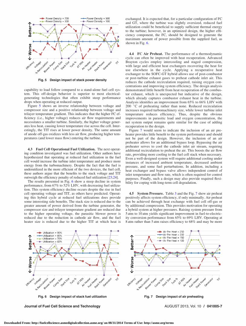
4.2 Fuel Cell Operational Power Density. The second oper-ating condition studied was fuel cell power density. Variations inoperating power density present a clear trade-off between cost andefficiency. Fuel cells operate closest to their ideal efficiency at lowpower densities, but cost per kW of capacity is inversely propor-tional to power density. Stand-alone fuel cell systems exhibitefficiency behavior closely mirroring the polarization curve and aretypically designed to operate at power densities that balance effi-ciency with power production or cost. A hybrid system, however,has the luxury of capturing a portion of the fuel cell-generated heat,thereby reducing the negative impact of operating at higher powerdensities. The balance of efficiency and power production (cost) ina hybrid system should thus tilt towards higher power density oper-ation than that one would chose for the same fuel cell operated in astand-alone system. Additionally, operating at high pressure per-mits even higher power densities with the same electrochemicalloss and heat generation. The impact of increasing or decreasingthe fuel cell power density is shown in Fig. 5.
Figure 5 affirms that lower operating power densities result inhigher efficiencies; however, the change is less for a hybrid sys-tem than for the FC itself. The operating voltage is directly pro-portional to FC efficiency and exhibits a greater differential dropwith increasing power density than the hybrid system efficiency.Reducing power density from 600 mW/cm2 to 200 mW/cm2
increased efficiency from 63% to 70% LHV, yet required a three-fold increase in stack size to achieve the same system power. Aninteresting attribute of FC technology is the capability to achievehigher efficiencies at reduced power. This holds true for thehybrid system as well, and dynamic studies indicate a greater
Table 3 Initial design results
Air preheat 0 �C 100 �C 200 �C
Voltage Volts 0.855 0.863 0.866DT trilayer �K 101.7 100.4 96.8Stack size Cells 306,400 303,700 302,200Stack power MW 84.1 83.5 83.4Gen power MW 16.6 17.1 17.0Blower power MW 0.70 0.55 0.40Efficiency % 65.0 66.1 66.4Comp size kg/s 74.4 87.7 107.2Turbine % % 16.5 17.0 17.0Air heater Plates 0 891 2762Fuel heater Plates 1042 1898 2270Turbine inlet K 1332 1220 1095Recirculation % 64.09 55.54 42.28Peak temp K 1072 1072 1071Cath outlet K 1061 1061 1061
Fig. 4 Design impact of stack temperature profile
041005-6 / Vol. 10, AUGUST 2013 Transactions of the ASME
Downloaded From: http://fuelcellscience.asmedigitalcollection.asme.org/ on 08/31/2014 Terms of Use: http://asme.org/terms
capability to load follow compared to a stand-alone fuel cell sys-tem. This off-design behavior is superior to most electrical-generating technologies that often exhibit steep performancedrops when operating at reduced output.
Figure 5 shows an inverse relationship between voltage andcompressor size and a positive relationship between voltage andtrilayer temperature gradient. This indicates that the higher FC ef-ficiency (i.e., higher voltage) reduces air flow requirements andnecessitates a smaller turbine. Similarly, the higher voltage gener-ates less heat, causing lower temperature rise across the cell. Inter-estingly, the TIT rises at lower power density. The same amountof anode off-gas oxidizes with less air flow, producing higher tem-peratures (and lower mass flow) entering the turbine.
4.3 Fuel Cell Operational Fuel Utilization. The next operat-ing condition investigated was fuel utilization. Other authors havehypothesized that operating at reduced fuel utilization in the fuelcell would increase the turbine inlet temperature and produce moreenergy from the turbomachinery. Despite the fact that the fuel isunderutilized in the more efficient of the two devices, the fuel cell,these authors argue that the benefits to the stack voltage and TIToutweigh the efficiency penalty of reduced fuel utilization [23,24].
The results presented in Fig. 6 show a steep decline in systemperformance, from 67% to 52% LHV, with decreasing fuel utiliza-tion. This system efficiency decline occurs despite the rise in fuelcell operating voltage and TIT, as others have predicted. Operat-ing this hybrid cycle at reduced fuel utilizations does providesome interesting side benefits. The stack size is reduced due to thegreater amount of power derived from the turbine generator, thecompressor size and trilayer temperature gradient are reduced dueto the higher operating voltage, the parasitic blower power isreduced due to the reduction in cathode air flow, and the fuelheater size is reduced due to the higher TIT at which heat is
exchanged. It is expected that, for a particular configuration of FCand GT, where the turbine was slightly oversized, reduced fuelutilization could be beneficial to supply sufficient thermal energyto the turbine; however, in an optimized design, the higher effi-ciency component, the FC, should be designed to generate themaximum amount of power possible from the supplied fuel, asshown in Fig. 6.
4.4 FC Air Preheat. The performance of a thermodynamiccycle can often be improved with heat recuperation. AdvancedBrayton cycles employ intercooling and staged compression,with large and efficient heat exchangers recovering the heat foruse elsewhere in the cycle. Applying a recuperative heatexchanger to the SOFC-GT hybrid allows use of post-combustoror post-turbine exhaust gases to preheat cathode inlet air. Thisreduces the cathode recirculation required, raising oxygen con-centrations and improving system efficiency. The design analysisdemonstrated little benefit from heat recuperation of the combus-tor exhaust, which is unexpected but indicative of the design,which already captures combustor exhaust heat in the turbine.Analysis identifies an improvement from 65% to 66% LHV with200 �C of preheating rather than none. Reduced recirculationincreases required turbomachinery size, while lower turbine inlettemperature reduces efficiency. Thus, despite the obviousimprovements in parasitic load and oxygen concentration, thenet system output remains quite similar for the case of addingrecuperation to the design.
Figure 7 would seem to indicate the inclusion of an air pre-heater provides little benefit to the system performance and shouldnot be part of the design. However, the inclusion of an airpreheater allows for an additional bypass loop. Bypassing the airpreheater serves to cool the cathode inlet air stream, requiringadditional recirculation to preheat the air. This boosts the air flowrate, providing more cooling to the fuel cell stack when necessary.Even a well-designed system will require additional cooling underinstances of increased ambient temperature, decreased ambientpressure, and some fuel perturbations. In addition, including aheat exchanger and bypass valve allows independent control ofinlet temperature and flow rate, which is often required for controlpurposes. Finally, such a design may also provide required flexi-bility for coping with long-term cell degradation.
4.5 System Pressure. Table 3 and the Fig. 7 show air preheatpositively affects system efficiency, if only minimally. Air preheatcan be achieved through heat exchange with fuel cell off-gas orby additional compression. This provides motivation for operatinga hybrid system at higher pressures. Raising system pressure from5 atm to 10 atm yields significant improvement in fuel-to-electric-ity conversion performance from 65% to 69% LHV. Operating at8 atm rather than 5 atm raises efficiency to 68% and may be more
Fig. 6 Design impact of stack fuel utilization Fig. 7 Design impact of air preheating
Fig. 5 Design impact of stack power density
Journal of Fuel Cell Science and Technology AUGUST 2013, Vol. 10 / 041005-7
Downloaded From: http://fuelcellscience.asmedigitalcollection.asme.org/ on 08/31/2014 Terms of Use: http://asme.org/terms

feasible in the near term than 10 atm. The voltage gains andreduced blower power requirements shown in Fig. 8 are largelyresponsible for these improvements.
4.6 Turbine Efficiency. Proper sizing of the two major com-ponents is a key factor in integrating a fuel cell and gas turbine.The previous analyses showed fuel cell operating voltage andefficiency produced large variations in optimal compressor size.Efficiency of the turbomachinery also impacts performance andthe relative sizing of the two primary components. The peak effi-ciency for the characteristic map is investigated between 70% and100%, with most real turbines operating between 85% and 95%efficiency.
The turbomachinery only produces 15% of the net power of ahybrid, but Fig. 9 demonstrates the large impact of turbine effi-ciency on overall system performance. A significant portion ofturbine power drives the compressor, operating at a fixed load.Thus, a 10% reduction in turbine power reduces net gas turbinepower by 25% and overall hybrid system power by 4%. Net tur-bine power diminishes quickly as the turbine operating point shiftsaway from the high-efficiency island of the performance map.This sensitivity highlights the importance of matching the turbineto the fuel cell, since an oversized turbine will operate well belowpeak efficiency.
Compressor efficiency is also highly dependent upon the oper-ating position of the turbomachinery and thus can compound theimpact of an improperly sized system. The effect of diminishingcompressor efficiency does not impact system performance asgreatly as turbine efficiency (see Fig. 10). Since the air flowpasses through at a lower temperature in the compressor, ineffi-ciencies of compression do not produce the same amount ofenergy loss as in the turbine. However, by looking at the genericaxial compressor map, one might suppose efficiency drops off
quicker when operation moves away from the compressor designpoint, resulting in similar system losses during off-designoperation.
4.7 Fuel Cell Operational Temperature. Average fuel celloperating temperature was the final design consideration investi-gated in this parametric sensitivity study (Fig. 11). The overpoten-tial parameters used in this study, particularly Ohmic losses, aresensitive to operating temperature. The resulting higher voltage athigher temperatures improves system performance by loweringcooling demands, shrinking the necessary turbomachinery, andthereby increasing the portion of power produced in the fuel cell.Heater size requirements are reduced, since heat transfer is moreeffective at the higher cathode exhaust temperatures. The hotterexhaust and smaller heat exchangers result in an increased TIT,thereby improving the turbomachinery efficiency as well.Increased fuel cell operational temperature primarily reduces thearea-specific resistance and increases cell degradation. The cur-rent results suggest that, if two fuel cell systems are capable ofsimilar performance and lifespan, the higher temperature systemis more amenable to hybridization. This is one of several reasonswhy high temperature SOFC technology should be pursued forthis application over the slightly lower temperature molten car-bonate technology.
5 Observed Trends
Choosing a design point for a FC/GT hybrid represents acomplex trade-off between cost and performance. Additionally,individual components may have different performance character-istics when integrated into any particular hybrid configuration.Figure 12 presents the performance impact each independentlystudied parameter has on total system performance. Each colored
Fig. 8 Design impact of system pressure
Fig. 9 Design impact of turbine efficiency
Fig. 10 Design impact of compressor efficiency
Fig. 11 Design impact of average cell temperature
041005-8 / Vol. 10, AUGUST 2013 Transactions of the ASME
Downloaded From: http://fuelcellscience.asmedigitalcollection.asme.org/ on 08/31/2014 Terms of Use: http://asme.org/terms

arrow represents the variation of a single parameter withinthe range of values outlined previously. This chart seeks to illus-trate the relative impact of each design parameter on completesystem performance. Figure 12 illustrates that power density andaverage trilayer temperature affect both voltage and efficiency,where compressor and turbine efficiencies affect only system effi-ciency. What is interesting about this chart is that the typicallydirect relationship between voltage and system efficiency in a FCdevice is skewed by the impact on the integrated system, particu-larly for fuel utilization and system pressure. Combining theeffects of changing several system parameters may be used toachieve optimum configurations for cost, efficiency, or durability.The curvature of each arrow implies nonlinearity in the applica-tion of each design choice; however, the trends toward increasingefficiency, voltage, recirculation, or turbine power fraction (aswill be seen in the next figures) will remain fixed. The combinedmanipulation of multiple design parameters may exhibit interact-ing benefits that may compound or contradict the trends, as shownin Figs. 12–14.
Turbomachinery efficiencies of the compressor and turbinehave little to no effect on voltage but a small effect on system effi-ciency. Figure 12 also shows the larger impact that turbine effi-ciency has on performance. This impact is due to the fact that thepower production in the turbine is much greater than consumptionin the compressor, and thus, 10% of additional losses in the tur-bine accounts for a greater total system energy loss than 10%losses in the compressor. This may be important when selectingturbomachinery that will operate at off-design conditions, notingthat it will be more important to maintain the expander near itshighest rated efficiency.
Figure 13 illustrates the relative impact each design considera-tion has on the necessary amount of cathode recirculation, assum-
ing a recuperating heat exchanger is not used, and the portion oftotal power provided by the gas turbine. This relationship is im-portant at the design stage for appropriately sizing the turbine andblower or designing an ejector. The amount of cathode recircula-tion will also largely determine the margin of controllability ofthe inlet temperature when using a variable air flow-rate turbine.
Interestingly, Fig. 13 illustrates a decoupled behavior, meaningthat some design choices affect primarily the amount of recircula-tion, while others affect the portion of power derived from the tur-bine. Increasing power density and decreasing fuel utilizationboth raise the turbine inlet temperature, having a similar effect asincreasing turbine efficiency. Increasing the temperature riseacross the FC reduces air flow and preheating needs that wereaccomplished through cathode recirculation. The excess energygiven off by the FC remains nearly constant; therefore, the turbineoutput is unaffected. Operating temperature provides an interest-ing exception, which impacts both recirculation and turbine outputby requiring additional preheating through recirculation and pro-viding less energy to the turbine, due to reduced Ohmic losses.Recirculation controls the air flow rate and temperature of thecathode. A change in stack temperature gradient requires a changein recirculation only and minimally affects turbine size and power.A system change that reduces FC efficiency typically increasesturbine output through additional heat generation that becomesavailable to the turbine. Examples of this include increases inpower density and fuel utilization and decreases in average oper-ating temperature. Optimally sizing the turbomachinery for thehybrid application is extremely important, but the relationshipbetween turbine size and fuel cell size is complicated. A slightlyoversized turbine can be throttled back to achieve a near optimaldesign, but a subscale turbine cannot provide the air flow neces-sary to meet the stack requirements.
It is therefore clear from Fig. 14 that the turbine should beexpected to output nearly 20% of the rated power of the FC stack.A compatible turbine must match the flow rate, inlet temperature,and power output specified by the hybrid configuration and thenominal fuel cell output. Precisely matching all three conditions isunlikely. Thus, the turbine will typically operate off-design, eitherby derating pressure, turbine inlet temperature, or both. The tur-bine selected for hybridization should be sized to provide at least120% of the air flow required by the FC, less any recirculation.This will often correspond to a low-pressure turbine nominallyproducing �20% of the rated fuel cell output. Reaching the speci-fied turbine inlet temperature can be achieved with additionalpost-FC oxidation, but the turbine should nominally be rated for200 �C greater than the operating temperature of the fuel cell.
Figure 14 illustrates two seemingly contradictory trends towardimproving system efficiency. Those design features that wouldimprove the turbine efficiency will improve system efficiency aswell as the portion of power contributed by the turbine. Those sys-tem parameters that increase the FC efficiency will decrease theenergy available to the expander and thus decrease the turbine
Fig. 12 Voltage and efficiency as dependent variables
Fig. 13 Recirculation and turbine % power as dependentvariables
Fig. 14 System efficiency and turbine % power as dependentvariables
Journal of Fuel Cell Science and Technology AUGUST 2013, Vol. 10 / 041005-9
Downloaded From: http://fuelcellscience.asmedigitalcollection.asme.org/ on 08/31/2014 Terms of Use: http://asme.org/terms

contribution while increasing system efficiency. To achieve opti-mal efficiency, the higher efficiency device, the FC, should con-tribute the greatest to the system output. This does not imply thatusing a smaller compressor will make a hybrid system performbetter; often this would cause the hybrid to fail completely. Whatthis trend implies is that designing a system that requires less airflow, and therefore a smaller compressor, implies an increase inFC efficiency. From a capital cost perspective, the turbomachinerywill be cheaper, per kW, than the FC stack and related compo-nents, and therefore, designs maximizing the power from the tur-bine will likely reduce the initial system cost.
6 Conclusions
The primary considerations when designing a hybrid FC/GTsystem are stack-power density, operating temperature, stack tem-perature rise, system pressure, fuel utilization, and the relativesize of the turbomachinery. These design selections and the FCstructure and material set, determine the operating voltage andtherefore the operating efficiency of the FC. These decisions, inturn, determine the air-flow requirements and heat available todrive the turbomachinery, with the difference in preheating andair flow provided by the cathode recirculation. High voltage, typi-cally achieved by operating at low power density, resulted in thehighest achievable system efficiency but the largest necessary FCstack size. Higher system pressure improves voltage and effi-ciency but requires sturdier components and applies mainly tolarge systems utilizing axial flow turbomachinery. Typical axialturbines are designed for high-pressure ratios, but utilization ofthe low pressure spool only could produce system pressures ame-nable to SOFC integration. System pressures between 4 and 8atmospheres would bring the design within the operating regimeof existing hardware. Higher fuel utilization actually has a nega-tive impact on fuel cell voltage for the configurations consideredhere but improves system performance by employing more fuel inthe electrochemical reactions. It is important to note that the effi-ciency penalty associated with reduced fuel utilization is less in ahybrid system than in a stand-alone FC system. It is extremelylikely that the optimal operating condition for a specific FC stackwill be at lower fuel utilization when hybridized with a gas tur-bine. The side benefits of lower fuel utilization include reduceddegradation effects, less chance of fuel starvation, more even spa-tial current and temperature distributions in the stack, and greaterdynamic operating flexibility. Higher operating temperaturesreduce ionic resistance, increase the turbine inlet temperaturecloser to nominal conditions, and raise overall hybrid system effi-ciency. The drawbacks of high temperature operation includeaccelerated voltage degradation and the requirement of potentiallyexotic interconnect and sealant materials. An optimal system maybe able to achieve ultrahigh fuel-to-electricity conversion effi-ciency but fall short of economic viability. The fuel cell stack rep-resents the single largest capital cost, so that minimizing the stacksize requirement reduces cost significantly. Achieving size reduc-tions primarily occurs by raising power density. In the currentstudy, increasing power density from 400 to 500 mW/cm2 reducesthe stack size by 25%, with only a 2.6% efficiency penalty. Elimi-nating the air preheating heat exchanger reduces the cost signifi-cantly but may diminish the ability to sufficiently control stackoperating temperature. Replacing air preheating with additionalcompression heating raises efficiency if the fuel cell can safelyhandle the pressure without cracking. Increased pressure improvespower density, allowing for additional trade-offs between efficiencyand reducing stack size even further. Optimizing the system withcost-minded design choices can produce a highly efficient (65%LHV or better) system with a substantially higher specific poweroutput than a stand-alone FC system.
Acknowledgment
The authors thank the U.S. Department of Defense Fuel CellProgram and Mr. Frank Holcomb of the Construction Engineering
Research Laboratory of the Engineer Research and DevelopmentCenter for partial support of the current work under contract num-ber W9132T-08-C-0003.
Nomenclature
A ¼ areaC ¼ thermal capacitance
Cp,v ¼ specific heat (constant pressure, constant volume)Flow ¼ turbomachinery flow rate
h ¼ enthalpyhc ¼ convection coefficientkc ¼ conduction coefficientm ¼ massM ¼ Mach numberN ¼ normalized turbomachinery parameterP ¼ pressure
PR ¼ pressure ratioQ ¼ sensible enthalpy of ions
RPM ¼ shaft speedRu ¼ universal gas constantT ¼ temperatureV ¼ velocity
References[1] FuelCell Energy Inc., 2006, “Record Electric Efficiency for DFC/Turbine
Unit,” Fuel Cells Bull., 2006(4), p. 10.[2] FuelCell Energy Inc., 2006, “FCE Power Plant in Earth Day Dedication at
Montana Clinic,” Fuel Cells Bull., 2006(6), p. 10.[3] Ghezel-Ayagh, H., Walzak, J., Patel, D., Daly, J., Maru, H., Sanderson, R., and
Livingood, W., 2005, “State of Direct Fuel Cell/Turbine Systems Devel-opment,” J. Power Sources, 152, pp. 219–225.
[4] Samuelsen, S. and Brouwer, J., 2009, “Fuel Cell/Gas Turbine Hybrid,” Ency-clopedia of Electrochemical Power Sources, 1st ed., J. Garche, ed., Elsevier,New York, pp. 124–134.
[5] Rao, A., MacLay, J., and Samuelsen, S., 2004, “Efficiency of ElectrochemicalSystems,” J. Power Sources, 134, pp. 181–184.
[6] Richards, G. A., McMillian, M. M., Gemmen, R. S., Rogers, W. A., and Cully,S. R., 2001, “Issues for Low-Emission, Fuel-Flexible Power Systems,” Prog.Energy Combust. Sci., 27, pp. 141–169.
[7] Lutsey, N., Brodrick, C. J., and Lipman, T., 2007, “Analysis of Potential FuelConsumption and Emissions Reductions From Fuel Cell Auxiliary Power Units(APUs) in Long-Haul Trucks,” Energy, 32, pp. 2428–2438.
[8] Lloyd, A. C., 1992, “California Clean Air Initiatives—The Role of Fuel Cells,”J. Power Sources, 37, pp. 241–253.
[9] Lloyd, A. C., 2000, “The California Fuel Cell Partnership: An Avenue to CleanAir,” J. Power Sources, 86, pp. 57–60.
[10] Ferrari, M. L., Liese, E., Tucker, D., Lawson, L., Traverso, A., and Massardo, A. F.,2007, “Transient Modeling of the NETL Hybrid Fuel Cell/Gas Turbine Facility andExperimental Validation,” ASME J. Eng. Gas Turbines Power, 129, pp. 1012–1019.
[11] Mueller, F., Brouwer, J., Jabbari, F., and Samuelsen, S., 2006, “Dynamic Simu-lation of an Integrated Solid Oxide Fuel Cell System Including Current-BasedFuel Flow Control,” ASME J. Fuel Cell Sci. Technol., 3, pp. 144–154.
[12] Yi, Y., Rao, A. D., Brouwer, J., and Samuelsen, S. G., 2004, “Analysis andOptimization of a Solid Oxide Fuel Cell and Intercooled Gas Turbine (SOFC-ICGT) Hybrid Cycle,” J. Power Sources, 132, pp. 77–85.
[13] Winkler, W., Nehter, P., Williams, M. C., Tucker, D., and Gemmen, R., 2006,“General Fuel Cell Hybrid Synergies and Hybrid System Testing Status,” J.Power Sources, 159, pp. 656–666.
[14] Brouwer, J., Jabbari, F., Leal, E. M., and Orr, T., 2005, “Analysis of a MoltenCarbonate Fuel Cell: Numerical Modeling and Experimental Validation,” J.Power Sources, 158, pp. 213–224.
[15] Roberts, R., Brouwer, J., Liese, E., and Gemmen, R. S., 2005, “Development ofControls for Dynamic Operation of Carbonate Fuel Cell-Gas Turbine HybridSystems,” Proceedings of ASME Turbo Expo 2005, Reno-Tahoe, NV, June6–9, ASME Paper No. GT2005-68774, pp. 325–331.
[16] Roberts, R., Brouwer, J., Liese, E., and Gemmen, R. S., 2005, “Dynamic Simu-lation of Carbonate Fuel Cell-Gas Turbine Hybrid Systems,” ASME J. Eng.Gas Turbines Power, 127, pp. 1–8.
[17] Rashidi, R., Berg, P., and Dincer, I., 2009, “Performance Investigation of aCombined MCFC System,” Int. J. Hydrogen Energy, 34, pp. 4395–4405.
[18] Roberts, R. A., and Brouwer, J., 2006, “Dynamic Simulation of a Pressurized 220kW Solid Oxide Fuel-Cell–Gas-Turbine Hybrid System: Modeled PerformanceCompared to Measured Results,” ASME J. Fuel Cell Sci. Technol., 3, pp. 18–25.
[19] Burbank, W., Witmer, D., and Holcomb, F., 2008, “Model of a Novel Pressur-ized SOFC-GT Hybrid Engine,” J. Power Sources, 193, pp. 656–664.
[20] Milewski, J., Miller, A., and Salacinski, J., 2006, “Off-Design Analysis ofSOFC Hybrid System,” Int. J. Hydrogen Energy, 32, pp. 687–698.
[21] Pratt, J. W., Brouwer, J., and Freeh, J. E., 2004, “Development of a Solid-OxideFuel Cell/Gas Turbine Hybrid System Model for Aerospace Applications,”
041005-10 / Vol. 10, AUGUST 2013 Transactions of the ASME
Downloaded From: http://fuelcellscience.asmedigitalcollection.asme.org/ on 08/31/2014 Terms of Use: http://asme.org/terms

Proceedings of ASME Turbo Expo 2004, Vienna, Austria, June 14–17, ASMEPaper No. GT2004-53616, pp. 371–379.
[22] McLarty, D. F., Samuelsen, S., and Brouwer, J., 2010, “Novel Dynamic Quasi-3-Dimensional High Temperature Fuel Cell Model With Internal Manifolding,”ASME 8th International Conference on Fuel Cell Science, Engineering andTechnology, Brooklyn, NY, June 14–16, ASME Paper No. FuelCell2010-33328, pp. 257–268.
[23] Yang, J. S., Sohn, J. L., and Ro, S. T., 2007, “Performance Characteristics of aSolid Oxide Fuel Cell/Gas Turbine Hybrid System With Various Part-LoadControl Modes,” J. Power Sources, 166, pp. 155–164.
[24] Kaneko, T., Brouwer, J., and Samuelsen, G. S., 2006, “Power andTemperature Control of Fluctuating Biomass Gas Fueled Solid Oxide FuelCell and Micro Gas Turbine Hybrid System,” J. Power Sources, 160, pp.316–325.
Journal of Fuel Cell Science and Technology AUGUST 2013, Vol. 10 / 041005-11
Downloaded From: http://fuelcellscience.asmedigitalcollection.asme.org/ on 08/31/2014 Terms of Use: http://asme.org/terms