Embed Size (px)
Citation preview
IEEE TRANSACTIONS ON ANTENNAS AND PROPAGATION, VOL. 62, NO. 3, MARCH 2014 1483
IV. CONCLUSION
By incorporating a varactor diode into its CLL-based NFRP ele-ment, a frequency-agile version of a passive fixed-value capacitor, ef-ficient monopole antenna was obtained. This frequency-agile versionincreased the effective fractional impedance bandwidth by more thana factor of four from its original value. The final configuration empha-sized the simplicity of its design; it was fabricated and tested. The mea-sured results demonstrated that the frequency-agile NFRP monopoleantenna prototype has good impedance matching, relatively high radia-tion efficiency, and stable and uniform radiation patterns over its entirefrequency-agile range, in good agreement with the predicted values.Because of the favorable simulation results presented for the larger tun-able capacitance range, alternate varactor diodes are being consideredto achieve a prototype with these design parameters and confirm thepredicted substantially larger frequency-agile range.
REFERENCES[1] C. A. Balanis, Antenna Theory: Analysis and Design, 3rd
ed. Hoboken, NJ, USA: Wiley Interscience, 2005.[2] Y. Dong and T. Itoh, “Metamaterial-based antennas,” Proc. IEEE, vol.
100, no. 7, pp. 2271–2285, July 2012.[3] J. Oh and K. Sarabandi, “Low profile, miniaturized, inductively cou-
pled capacitively loaded monopole antenna,” IEEE Trans. AntennasPropag., vol. 60, no. 3, pp. 1206–1213, Mar. 2012.
[4] R. W. Ziolkowski, P. Jin, and C.-C. Lin, “Metamaterial-inspired engi-neering of antennas,” Proc. IEEE, vol. 99, no. 10, pp. 1720–1731, Oct.2011.
[5] L. J. Chu, “Physical limitations of omni-directional antennas,” J. Appl.Phys., vol. 19, pp. 1163–1175, Dec. 1948.
[6] H. L. Thal, “New radiation limits for spherical wire antennas,” IEEETrans. Antennas Propag., vol. 54, no. 10, pp. 2757–2763, Oct. 2006.
[7] A. Petosa, “An overview of tuning techniques for frequency-agile an-tennas,” IEEE Antennas Propag. Mag., vol. 54, pp. 271–296, 2012.
[8] M. Hassan and G. V. Eleftheriades, “A compact frequency-recon-figurable metamaterial-inspired antenna,” IEEE Antennas WirelessPropag. Lett., vol. 10, pp. 1154–1157, 2011.
[9] S. Zhu, D. G. Holtby, K. L. Ford, A. Tennant, and R. J. Langley, “Com-pact low frequency varactor loaded tunable SRR antenna,” IEEE Trans.Antennas Propag., vol. 61, no. 4, pp. 2757–2763, Apr. 2013.
[10] Y. Yu, J. Xiong, H. Li, and S. He, “An electrically small frequency re-configurable antenna with a wide tuning range,” IEEE Antennas Wire-less Propag. Lett., vol. 10, pp. 103–106, 2011.
[11] A. Erentok and R. W. Ziolkowski, “Metamaterial-inspired efficientelectrically small antennas,” IEEE Trans. Antennas Propag., vol. 56,no. 3, pp. 691–707, Mar. 2008.
[12] P. Jin and R. W. Ziolkowski, “Multi-frequency, linear and circular po-larized, metamaterial-inspired, near-field resonant parasitic antennas,”IEEE Trans. Antennas Propag., vol. 59, no. 5, pp. 1446–1459, May2011.
[13] N. Zhu, R. W. Ziolkowski, and H. Xin, “Electrically small GPSL1 rectennas,” IEEE Antennas Wireless Propag. Lett., vol. 10, pp.935–938, 2011.
[14] N. Zhu and R. W. Ziolkowski, “Active metamaterial-inspiredbroad-bandwidth, efficient, electrically small antennas,” IEEE An-tennas Wireless Propag. Lett., vol. 10, pp. 1582–1585, 2011.
[15] N. Zhu and R.W. Ziolkowski, “Design andmeasurements of an electri-cally small, broad bandwidth, non-Foster circuit-augmented protractorantenna,” Appl. Phys. Lett., vol. 101, p. 024107, Jul. 2012.
[16] K. B. Alici and E. Ozbay, “Radiation properties of a split ring resonatorand monopole composite,” Phys. Stat. Sol. (B), vol. 244, no. 4, pp.1192–1197, Mar. 2007.
[17] K. B. Alici and E. Ozbay, “Electrically small split ring resonator an-tennas,” J. Appl. Phys., vol. 101, p. 083104, Apr. 2007.
[18] O. S. Kim and O. Breinbjerg, “Miniaturised self-resonant split-ring res-onator antenna,” Electron. Lett., vol. 45, no. 4, pp. 196–197, Feb. 2009.
[19] [Online]. Available: http://www.skyworksinc.com/uploads/docu-ments/SMV1770_Series_200095I.pdf
[20] E. Antonino-Daviu, M. Cabedo-Fabrés, M. Ferrando-Bataller, and V.M. R. Peñarrocha, “Modal analysis and design of band-notched UWBplanar monopole antennas,” IEEE Trans. Antennas Propag., vol. 58,no. 5, pp. 1457–1467, May 2010.
[21] Y.-Y. Bai, S. Xiao, M.-C. Tang, Z.-F. Ding, and B. Wang, “Wide-anglescanning phased array with pattern reconfigurable elements,” IEEETrans. Antennas Propag., vol. 59, no. 11, pp. 4071–4076, Nov. 2011.
[22] R. Ludwig and P. Bretchko, RF Circuit Design, Theory and Applica-tion, 1st ed. Englewood Cliffs, NJ, USA: Prentice-Hall, 2000.
[23] M.-C. Tang and R. W. Ziolkowski, “A frequency agile, ultralow-pro-file, complementary split ring resonator-based electrically small an-tenna,” Microw. Opt. Technol. Lett., vol. 55, no. 10, pp. 2425–2428,Oct. 2013.
[24] R. Cutshall and R. W. Ziolkowski, “Performance characteristics ofplanar and three-dimensional versions of a frequency agile electricallysmall antenna,” IEEE Antennas Propag. Mag., submitted for publica-tion.
Hybrid Fractal Shape Planar Monopole Antenna CoveringMultiband Wireless Communications With MIMOImplementation for Handheld Mobile Devices
Yogesh Kumar Choukiker, Satish K. Sharma, and Santanu K. Behera
Abstract—A hybrid fractal shape planar monopole antenna cov-ering multiple wireless communication bands is presented for mul-tiple-input-multiple-output (MIMO) implementation for handheld mobiledevices. The proposed structure is the combination of Minkowski islandcurve and Koch curve fractals. It is placed with edge to edge separationof at 1.75 GHz. The T-shape strip is inserted and rectangularslot is etched at top side of ground plane, respectively to improve theimpedance matching and isolation between the antennas. A measuredimpedance matching fractional bandwidths ( dB) are 14%from 1.65 GHz to 1.9 GHz for the band 1 and 80% from 2.68 GHz to6.25 GHz for the band 2. Acceptable agreement is obtained betweenthe simulated and measured antenna performance parameters. Thesecharacteristics demonstrate that the proposed antenna is an attractivecandidate for handheld mobile devices.
Index Terms—Hybrid fractal antenna, multiple-input-multiple-output(MIMO), multiband wireless communications, planar monopole.
I. INTRODUCTION
There is a great demand to enhance data throughput in hand-held/portable devices for wireless communications such as live highdefinition television (HDTV) broadcast, online game, real-time videostreaming, and mobile electronic devices [1]. Fractal antennas allowcompact, multiband and broadband antenna designs [2], [3]. Most
Manuscript received February 11, 2013; revised November 11, 2013; ac-cepted December 08, 2013. Date of publication December 17, 2013; date ofcurrent version February 27, 2014. The work of Y. K. Choukiker was supportedby the TEQIP-II, National Institute of Technology, Rourkela, Govt. of India.Y. K. Choukiker was with the Antenna and Microwave Laboratory (AML),
Department of Electrical and Computer Engineering, San Diego State Uni-versity, San Diego, CA 92182 USA. He is now with the Microwave andAntenna Design Laboratory, Department of Electronics and CommunicationEngineering, National Institute of Technology, Rourkela, India (e-mail:[email protected])S. K. Sharma is with the Antenna and Microwave Laboratory (AML), De-
partment of Electrical and Computer Engineering, San Diego State University,San Diego, CA 92182 USA (e-mail: [email protected]).S. K. Behera is with the Microwave and Antenna Design Laboratory, De-
partment of Electronics and Communication Engineering, National Institute ofTechnology, Rourkela, India (e-mail: [email protected]).Color versions of one or more of the figures in this communication are avail-
able online at http://ieeexplore.ieee.org.Digital Object Identifier 10.1109/TAP.2013.2295213
0018-926X © 2013 IEEE. Personal use is permitted, but republication/redistribution requires IEEE permission.See http://www.ieee.org/publications_standards/publications/rights/index.html for more information.
1484 IEEE TRANSACTIONS ON ANTENNAS AND PROPAGATION, VOL. 62, NO. 3, MARCH 2014
Fig. 1. Three initial stages of generation (a) Koch curve fractal and(b) Minkowski curve fractal geometries.
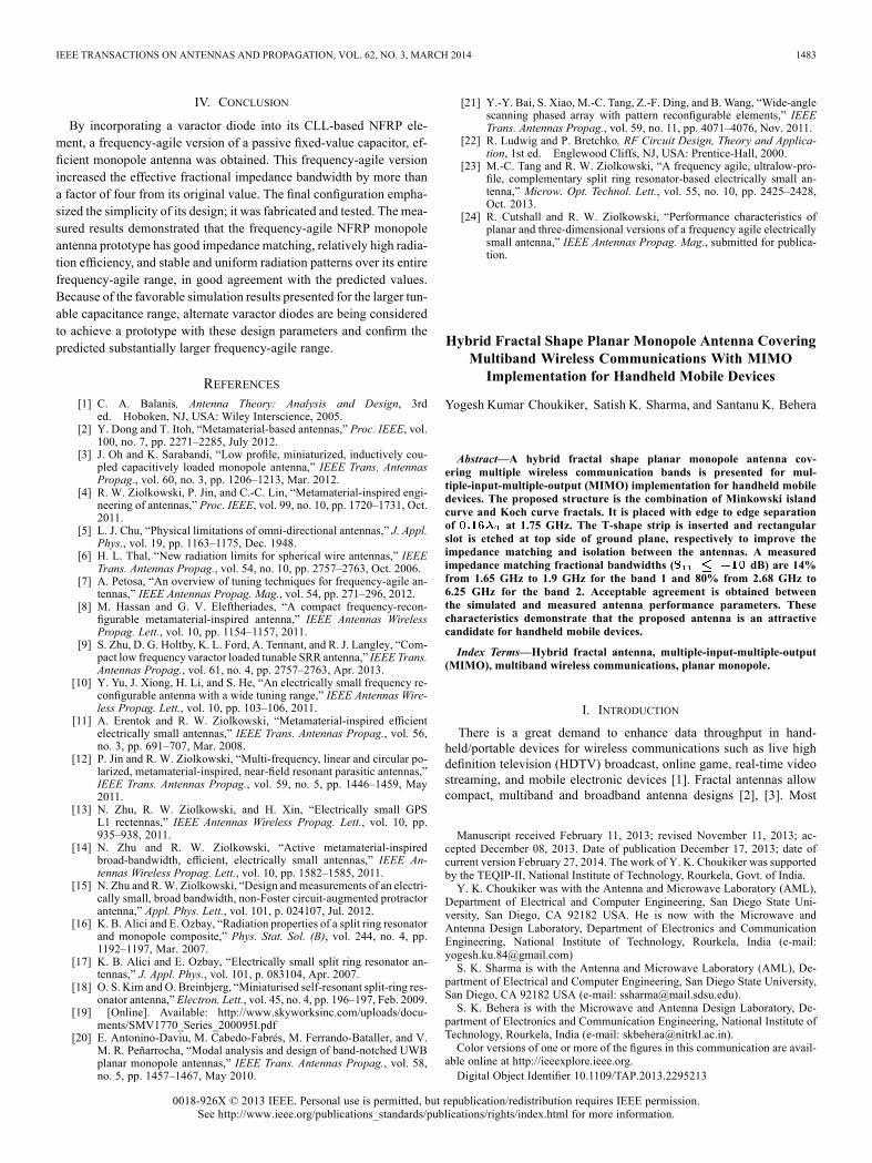
Fig. 2. Geometry of the proposed hybrid fractal MIMO antenna: (a) front view,(b) top view, and (c) hybrid fractal design dimensions.
fractal objects have self-similar shape, with different scales [4]. Thefractal shape can be carried out by applying the infinite number ofiterations using multiple reduction copy machine (MRCM) algorithm[5]. The space filling property, when applied to an antenna element,leads to an increase of the electrical length. The more convolutedand longer surface currents result in lowering the antenna resonantfrequency for a given overall extension of the resonator. The fractalminiaturization technique has already been applied to Koch wiremonopole [6], combination of fractal geometries [7]–[11], and theSierpinski fractal-shape antennas [12]–[14]. Although the essence ofthis technique falls into the inductive loading, the radiation patterns ofthe antennas derived from this technique are maintained because ofthe self-similarities of the fractals.Recently, theoretical and experimental published articles [15]–[23]
confirm the superior data rate, multipath fading reduction andco-channel interference suppression capability when the antennasare implemented in MIMO arrangements. Moreover, the trend formobile terminals nowadays is to accommodate the increased numberof wireless communication applications.In [15], [16], MIMO implementation of the microstrip antennas
is applied for the wireless digital television (DTV) media playerscovering long term evaluation (LTE) bands and for USB dongle forwireless LTE/WLAN bands, respectively. Various techniques havebeen reported to enhance the isolation between the MIMO antenna
Fig. 3. Simulated scattering parameters and isolation of the MIMO antennaswith different iterations.
Fig. 4. Simulated scattering parameters and isolation of the MIMO antennaswith different configuration of the grooved area and T-shape strip.
Fig. 5. Simulated surface current distributions of the MIMO antennas: (a) An-tenna 1 at 1.75 GHz and 4.5 GHz and (b) Antenna 2 at 1.75 GHz and 4.5 GHz.
elements. Further, there is demand for diversity antennas in theLTE/WiFi/Wimax/WLAN bands [17].In [18], the authors reduced the isolation between the antennas using
bent slit and a metal strip between the two antennas. In [19], the authorsused neutralization lines for achieving the isolation. The isolation/mu-tual-coupling between two pots are good across the bandwidth. How-ever, it cannot cover the most desired bands, such as LTE and UMTS inlimited antenna volume. Another paper [20] reports a quad bandMIMOantenna for wireless communication terminal, where the radiating ele-ment is combination of the C-shaped slot and T-shaped slit. In [21], theauthors show the closely spaced element with large bandwidth. How-ever, the relatively large antenna volume and strong coupling betweenits two elements restrict its applications. In [22], a dual band MIMOantenna with two back-to-back monopoles in symmetric configurationis presented. Here, radiating elements are placed on a large volume ofmetal case which makes it difficult to be applied in a hand held/porta-bles mobile devices.For fractal MIMO implementation in [23], the authors used a Koch
curve edge in microstrip patch. Another fractal MIMO antenna in [17]
IEEE TRANSACTIONS ON ANTENNAS AND PROPAGATION, VOL. 62, NO. 3, MARCH 2014 1485
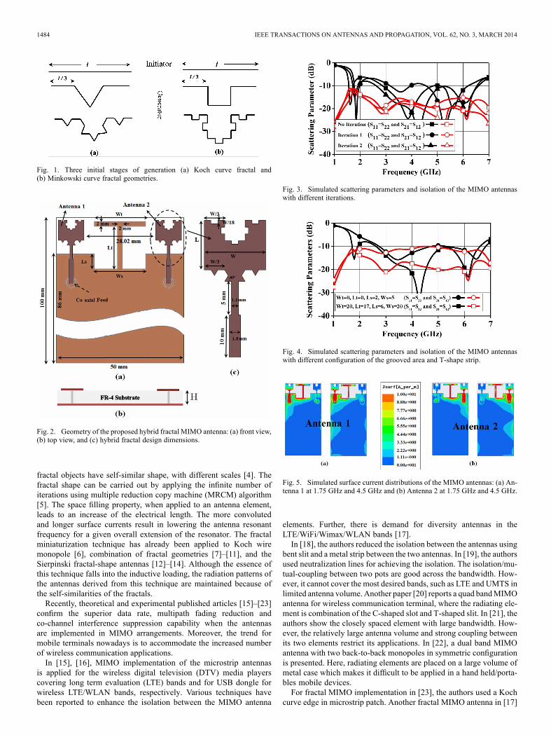
Fig. 6. Simulated 3D gain radiation patterns for the antenna 1 (a), (c), (e), and (g) and the antenna 2 (b), (d), (f), and (h). (a), (b) are at 1.75 GHz; (c), (d) are at3 GHz; (e), (f) are at 4.5 GHz; and (g), (h) are at 6 GHz.
shows Koch curve and Minkowski curve based fractal MIMO imple-mentation for multiband applications. To enhance data throughput forwireless communications, multiple-input-multiple-output (MIMO) an-tennas should be implemented in a handheld/portable device. Also,to support several wireless communication applications on a device,multiband antennas are desired. Such a task becomes even more chal-lenging when, besides multiband operations, a high degree of miniatur-ization is required. Fractal structure, having self-similarity and spacefilling properties, can produce a very long length or a wide surfacearea in limited space. Therefore, in this communication, we proposea hybrid fractal shaped planar monopole antenna as a radiating el-ement for the MIMO implementation. It is a combination of Kochcurve andMinkowski island fractals with compact size of 10 10mm
. The proposed antenna covers LTE/WiFi/WiMAX/WLANwireless communication bands with near omni-directional radiationpatterns. Here, a defected ground plane structure is used (a combina-tion of rectangular grooved area and T-shaped strip) to obtained highisolation between the two MIMO antenna elements. Parametric studyis performed to analyze the effect of the T-shaped strip and groovedground plane parameters on the operating frequency as well as the iso-lation between the two antennas. The Ansys high frequency structuresimulator (HFSS) version 14 was used for modeling and analysis of theproposed antenna. In Section II, geometry of the proposed antenna andsimulation results are presented. Experimental verification of proposedantenna is discussed in Section III. Finally, Section IV concludes majorfindings.
II. ANTENNA GEOMETRY AND SIMULATIONS RESULTS
A. Antenna Geometry
The recursive procedure of the Koch and Minkowski island curvefractals are shown in Fig. 1. To obtain the self-similarity dimensions,the geometry is scaled down, but with identical copies of itself. If thereare such copies of original geometry scaled down by a function ,the similarity dimension is defined in the following:
(1)
For example, a square can be divided into four copies of 1/2 scale,nine copies of 1/3 scale, 16 copies of 1/4 scale, or copies of 1/nscale. Substituting in the above formula, the dimension of the geom-etry is ascertained to be 2. This approach can be followed in deter-mining the dimension of fractal geometries. For construction of Kochand Minkowski curve fractals, one can start with a straight-linecalled initiator and it is divided into three equal parts . In case of
TABLE IDIMENSIONS OF PROPOSED HYBRID FRACTAL MIMO ANTENNA
the Koch curve, the middle segment is divided and replaced with twoother segment of the same length. Besides, in case of the Minkowskiisland curve, the middle segment is replaced by two horizontal anda vertical segment of equal lengths. This is the first iterated versionof geometry and is called “generator” for higher iterations, as shownin Fig. 1(a) and (b). This procedure is iterated recursively to result inself-similar fractal geometry by taking the order of iteration and thedimension (1) as the input parameters. Basically, individual itera-tions are applied to both the Koch and Minkowski curves which arethen combined to get hybrid fractal geometry. For further optimiza-tions, dimension “ ” for both fractals are varied simultaneously.Geometry of the proposed hybrid fractal MIMO antenna is shown
in Fig. 2(a) along with its final dimensions as listed in Table I. Kochcurve fractal and Minkowski island curve fractal are applied to theedges of the square patch up to the second iteration. Its dimensionsare also indicated in Fig. 2(c). The motivation behind using such ge-ometry is to improve the space filling, a feature that translates into re-duced antenna physical size and for the increased number of resonantfrequency bands. The antenna is fed through the 50 SMA coaxialprobe connected to the microstrip line with matching section over thegrooved ground plane. As shown in Fig. 2, MIMO antenna consistsof the edge-to-edge separation of 28.02 mm ( at 1.75 GHz) be-tween the two symmetrical hybrid fractal radiating elements. The FR-4
substrate of size 100 50 mm with height is used. Theradiating elements are placed on one side of the substrateand grooved ground plane of size 86 50 mm is located on the otherside. It should be noted that the grooved area ( and is locatedon top of the ground plane with T-shape strip ( and with fixedwidth of 2 mm. It is introduced to improve the impedance matchingand isolation between the antennas.
B. Simulation Results
As the number of iterations increase, the average electrical lengthof the monopole also increases, just like the inductive loading and slotloading techniques reported in [24], [25], which consequently, lowersthe operating frequency of the proposed antenna and leads to an effec-tive antennaminiaturization. However, for the iterations higher than thesecond, the reduction of operating frequency is not achievable since
1486 IEEE TRANSACTIONS ON ANTENNAS AND PROPAGATION, VOL. 62, NO. 3, MARCH 2014
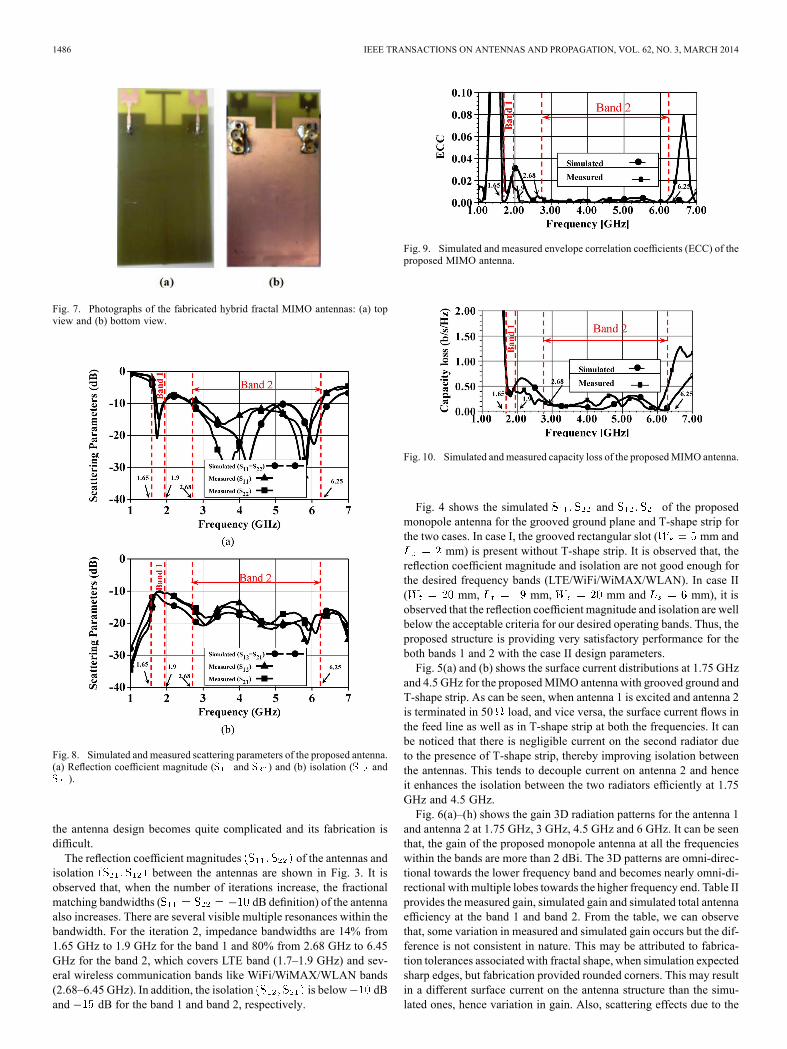
Fig. 7. Photographs of the fabricated hybrid fractal MIMO antennas: (a) topview and (b) bottom view.
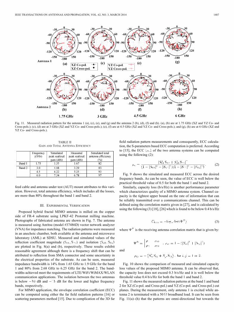
Fig. 8. Simulated and measured scattering parameters of the proposed antenna.(a) Reflection coefficient magnitude ( and ) and (b) isolation ( and).
the antenna design becomes quite complicated and its fabrication isdifficult.The reflection coefficient magnitudes of the antennas and
isolation between the antennas are shown in Fig. 3. It isobserved that, when the number of iterations increase, the fractionalmatching bandwidths ( dB definition) of the antennaalso increases. There are several visible multiple resonances within thebandwidth. For the iteration 2, impedance bandwidths are 14% from1.65 GHz to 1.9 GHz for the band 1 and 80% from 2.68 GHz to 6.45GHz for the band 2, which covers LTE band (1.7–1.9 GHz) and sev-eral wireless communication bands like WiFi/WiMAX/WLAN bands(2.68–6.45 GHz). In addition, the isolation is below dBand dB for the band 1 and band 2, respectively.
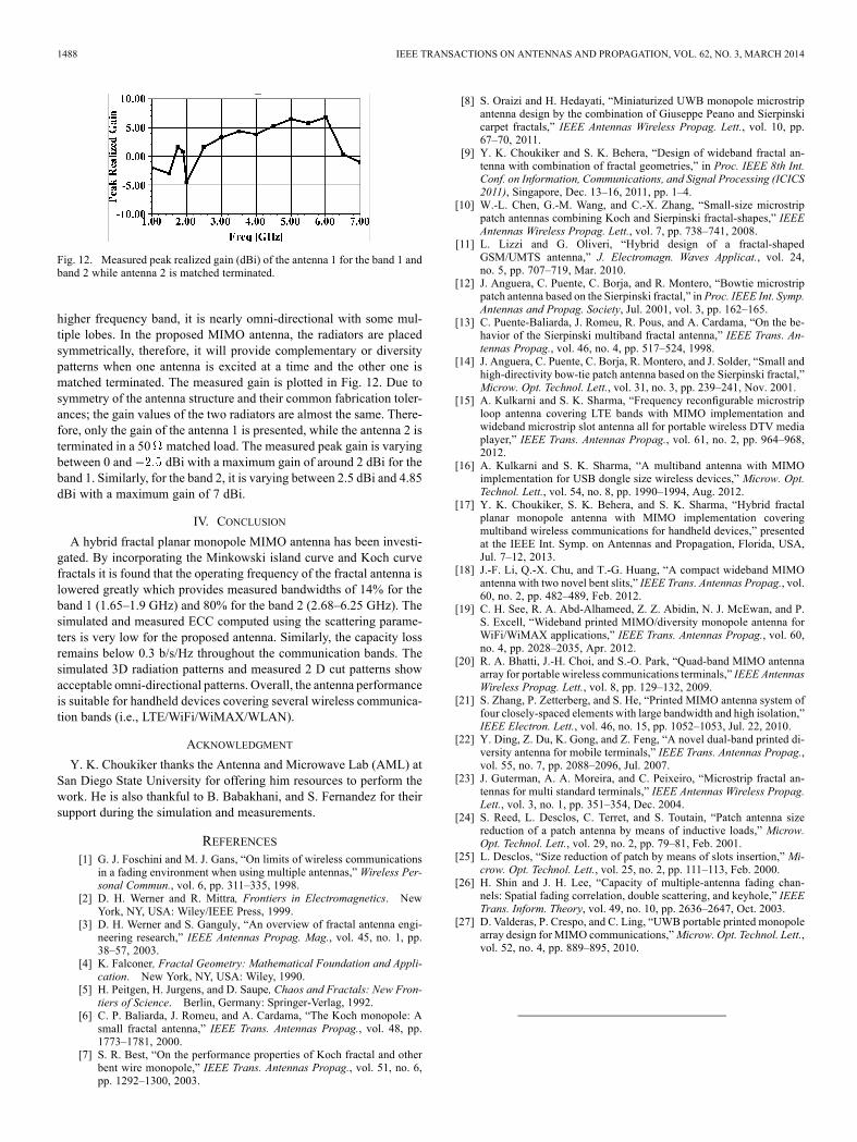
Fig. 9. Simulated and measured envelope correlation coefficients (ECC) of theproposed MIMO antenna.
Fig. 10. Simulated andmeasured capacity loss of the proposedMIMO antenna.
Fig. 4 shows the simulated and of the proposedmonopole antenna for the grooved ground plane and T-shape strip forthe two cases. In case I, the grooved rectangular slot ( mm and
mm) is present without T-shape strip. It is observed that, thereflection coefficient magnitude and isolation are not good enough forthe desired frequency bands (LTE/WiFi/WiMAX/WLAN). In case II( mm, mm, mm and mm), it isobserved that the reflection coefficient magnitude and isolation are wellbelow the acceptable criteria for our desired operating bands. Thus, theproposed structure is providing very satisfactory performance for theboth bands 1 and 2 with the case II design parameters.Fig. 5(a) and (b) shows the surface current distributions at 1.75 GHz
and 4.5 GHz for the proposedMIMO antenna with grooved ground andT-shape strip. As can be seen, when antenna 1 is excited and antenna 2is terminated in 50 load, and vice versa, the surface current flows inthe feed line as well as in T-shape strip at both the frequencies. It canbe noticed that there is negligible current on the second radiator dueto the presence of T-shape strip, thereby improving isolation betweenthe antennas. This tends to decouple current on antenna 2 and henceit enhances the isolation between the two radiators efficiently at 1.75GHz and 4.5 GHz.Fig. 6(a)–(h) shows the gain 3D radiation patterns for the antenna 1
and antenna 2 at 1.75 GHz, 3 GHz, 4.5 GHz and 6 GHz. It can be seenthat, the gain of the proposed monopole antenna at all the frequencieswithin the bands are more than 2 dBi. The 3D patterns are omni-direc-tional towards the lower frequency band and becomes nearly omni-di-rectional with multiple lobes towards the higher frequency end. Table IIprovides the measured gain, simulated gain and simulated total antennaefficiency at the band 1 and band 2. From the table, we can observethat, some variation in measured and simulated gain occurs but the dif-ference is not consistent in nature. This may be attributed to fabrica-tion tolerances associated with fractal shape, when simulation expectedsharp edges, but fabrication provided rounded corners. This may resultin a different surface current on the antenna structure than the simu-lated ones, hence variation in gain. Also, scattering effects due to the
IEEE TRANSACTIONS ON ANTENNAS AND PROPAGATION, VOL. 62, NO. 3, MARCH 2014 1487
Fig. 11. Measured radiation pattern for the antenna 1 (a), (c), (e), and (g) and the antenna 2 (b), (d), (f) and (h). (a), (b) are at 1.75 GHz (XZ and YZ Co- andCross-pols.); (c), (d) are at 3 GHz (XZ and YZ Co- and Cross-pols.); (e), (f) are at 4.5 GHz (XZ and YZ Co- and Cross-pols.); and (g), (h) are at 6 GHz (XZ andYZ Co- and Cross-pols.).
TABLE IIGAIN AND TOTAL ANTENNA EFFICIENCY
feed cable and antenna under test (AUT) mount attributes to this vari-ation. However, total antenna efficiency, which includes all the losses,are more than 80% throughout the band 1 and band 2.
III. EXPERIMENTAL VERIFICATION
Proposed hybrid fractal MIMO antenna is milled on the copperside of FR-4 substrate using LPKF-42 Protomat milling machine.Photographs of fabricated antenna are shown in Fig. 7. The antennais measured using Anritsu (model #37486D) vector network analyzer(VNA) for impedance matching. The radiation patterns were measuredin an anechoic chamber, both available at the antenna and microwavelaboratory (AML) at SDSU. Measured and simulated values of thereflection coefficient magnitude and isolationare plotted in Fig. 8(a) and (b), respectively. These results exhibitreasonable agreement although there is a frequency shift that can beattributed to reflection from SMA connector and some uncertainty inthe electrical properties of the substrate. As can be seen, measuredimpedance bandwidth is 14% from 1.65 GHz to 1.9 GHz for the band1 and 80% from 2.68 GHz to 6.25 GHz for the band 2. The band-widths achieved meet the requirements of LTE/WiFi/WiMAX/WLANcommunication applications. The isolation between the two antennasis below dB and dB for the lower and higher frequencybands, respectively.For MIMO application, the envelope correlation coefficient (ECC)
can be computed using either the far field radiation patterns [16] orscattering parameters method [15]. Due to complication of the 3D far
field radiation pattern measurements and consequently, ECC calcula-tion, the S-parameters based ECC computation is preferred. Accordingto [15], the ECC of the two antenna systems can be computedusing the following (2):
(2)
Fig. 9 shows the simulated and measured ECC across the desiredfrequency bands. As can be seen, the value of ECC is well below thepractical threshold value of 0.5 for both the band 1 and band 2.Similarly, capacity loss (b/s/Hz) is another performance parameter
which characterizes quality of a MIMO antenna system. Channel ca-pacity is the tightest upper bound on the rate of information that canbe reliably transmitted over a communications channel. This can bedefined using the correlation matrix given in [27], and is calculated byusing the following (3) [18], [26] which is found to be below 0.4 b/s/Hz
(3)
where is the receiving antenna correlation matrix that is given by:
and
Fig. 10 shows the comparison of measured and simulated capacityloss values of the proposed MIMO antenna. It can be observed that,the capacity loss does not exceed 0.3 b/s/Hz and it is well below thethreshold value 0.4 b/s/Hz for both the band 1 and band 2.Fig. 11 shows the measured radiation patterns at the band 1 and band
2 for XZ (Co-pol. and Cross-pol.) and YZ (Co-pol. and Cross-pol.) cutplanes. During the measurement, only antenna 1 is excited while an-tenna 2 is terminated with a 50 broadband load. It can be seen fromFig. 11(a)–(h) that the patterns are omni-directional but towards the
1488 IEEE TRANSACTIONS ON ANTENNAS AND PROPAGATION, VOL. 62, NO. 3, MARCH 2014
Fig. 12. Measured peak realized gain (dBi) of the antenna 1 for the band 1 andband 2 while antenna 2 is matched terminated.
higher frequency band, it is nearly omni-directional with some mul-tiple lobes. In the proposed MIMO antenna, the radiators are placedsymmetrically, therefore, it will provide complementary or diversitypatterns when one antenna is excited at a time and the other one ismatched terminated. The measured gain is plotted in Fig. 12. Due tosymmetry of the antenna structure and their common fabrication toler-ances; the gain values of the two radiators are almost the same. There-fore, only the gain of the antenna 1 is presented, while the antenna 2 isterminated in a 50 matched load. The measured peak gain is varyingbetween 0 and dBi with a maximum gain of around 2 dBi for theband 1. Similarly, for the band 2, it is varying between 2.5 dBi and 4.85dBi with a maximum gain of 7 dBi.
IV. CONCLUSION
A hybrid fractal planar monopole MIMO antenna has been investi-gated. By incorporating the Minkowski island curve and Koch curvefractals it is found that the operating frequency of the fractal antenna islowered greatly which provides measured bandwidths of 14% for theband 1 (1.65–1.9 GHz) and 80% for the band 2 (2.68–6.25 GHz). Thesimulated and measured ECC computed using the scattering parame-ters is very low for the proposed antenna. Similarly, the capacity lossremains below 0.3 b/s/Hz throughout the communication bands. Thesimulated 3D radiation patterns and measured 2 D cut patterns showacceptable omni-directional patterns. Overall, the antenna performanceis suitable for handheld devices covering several wireless communica-tion bands (i.e., LTE/WiFi/WiMAX/WLAN).
ACKNOWLEDGMENT
Y. K. Choukiker thanks the Antenna and Microwave Lab (AML) atSan Diego State University for offering him resources to perform thework. He is also thankful to B. Babakhani, and S. Fernandez for theirsupport during the simulation and measurements.
REFERENCES[1] G. J. Foschini and M. J. Gans, “On limits of wireless communications
in a fading environment when using multiple antennas,” Wireless Per-sonal Commun., vol. 6, pp. 311–335, 1998.
[2] D. H. Werner and R. Mittra, Frontiers in Electromagnetics. NewYork, NY, USA: Wiley/IEEE Press, 1999.
[3] D. H. Werner and S. Ganguly, “An overview of fractal antenna engi-neering research,” IEEE Antennas Propag. Mag., vol. 45, no. 1, pp.38–57, 2003.
[4] K. Falconer, Fractal Geometry: Mathematical Foundation and Appli-cation. New York, NY, USA: Wiley, 1990.
[5] H. Peitgen, H. Jurgens, and D. Saupe, Chaos and Fractals: New Fron-tiers of Science. Berlin, Germany: Springer-Verlag, 1992.
[6] C. P. Baliarda, J. Romeu, and A. Cardama, “The Koch monopole: Asmall fractal antenna,” IEEE Trans. Antennas Propag., vol. 48, pp.1773–1781, 2000.
[7] S. R. Best, “On the performance properties of Koch fractal and otherbent wire monopole,” IEEE Trans. Antennas Propag., vol. 51, no. 6,pp. 1292–1300, 2003.
[8] S. Oraizi and H. Hedayati, “Miniaturized UWB monopole microstripantenna design by the combination of Giuseppe Peano and Sierpinskicarpet fractals,” IEEE Antennas Wireless Propag. Lett., vol. 10, pp.67–70, 2011.
[9] Y. K. Choukiker and S. K. Behera, “Design of wideband fractal an-tenna with combination of fractal geometries,” in Proc. IEEE 8th Int.Conf. on Information, Communications, and Signal Processing (ICICS2011), Singapore, Dec. 13–16, 2011, pp. 1–4.
[10] W.-L. Chen, G.-M. Wang, and C.-X. Zhang, “Small-size microstrippatch antennas combining Koch and Sierpinski fractal-shapes,” IEEEAntennas Wireless Propag. Lett., vol. 7, pp. 738–741, 2008.
[11] L. Lizzi and G. Oliveri, “Hybrid design of a fractal-shapedGSM/UMTS antenna,” J. Electromagn. Waves Applicat., vol. 24,no. 5, pp. 707–719, Mar. 2010.
[12] J. Anguera, C. Puente, C. Borja, and R. Montero, “Bowtie microstrippatch antenna based on the Sierpinski fractal,” in Proc. IEEE Int. Symp.Antennas and Propag. Society, Jul. 2001, vol. 3, pp. 162–165.
[13] C. Puente-Baliarda, J. Romeu, R. Pous, and A. Cardama, “On the be-havior of the Sierpinski multiband fractal antenna,” IEEE Trans. An-tennas Propag., vol. 46, no. 4, pp. 517–524, 1998.
[14] J. Anguera, C. Puente, C. Borja, R. Montero, and J. Solder, “Small andhigh-directivity bow-tie patch antenna based on the Sierpinski fractal,”Microw. Opt. Technol. Lett., vol. 31, no. 3, pp. 239–241, Nov. 2001.
[15] A. Kulkarni and S. K. Sharma, “Frequency reconfigurable microstriploop antenna covering LTE bands with MIMO implementation andwideband microstrip slot antenna all for portable wireless DTV mediaplayer,” IEEE Trans. Antennas Propag., vol. 61, no. 2, pp. 964–968,2012.
[16] A. Kulkarni and S. K. Sharma, “A multiband antenna with MIMOimplementation for USB dongle size wireless devices,” Microw. Opt.Technol. Lett., vol. 54, no. 8, pp. 1990–1994, Aug. 2012.
[17] Y. K. Choukiker, S. K. Behera, and S. K. Sharma, “Hybrid fractalplanar monopole antenna with MIMO implementation coveringmultiband wireless communications for handheld devices,” presentedat the IEEE Int. Symp. on Antennas and Propagation, Florida, USA,Jul. 7–12, 2013.
[18] J.-F. Li, Q.-X. Chu, and T.-G. Huang, “A compact wideband MIMOantenna with two novel bent slits,” IEEE Trans. Antennas Propag., vol.60, no. 2, pp. 482–489, Feb. 2012.
[19] C. H. See, R. A. Abd-Alhameed, Z. Z. Abidin, N. J. McEwan, and P.S. Excell, “Wideband printed MIMO/diversity monopole antenna forWiFi/WiMAX applications,” IEEE Trans. Antennas Propag., vol. 60,no. 4, pp. 2028–2035, Apr. 2012.
[20] R. A. Bhatti, J.-H. Choi, and S.-O. Park, “Quad-band MIMO antennaarray for portable wireless communications terminals,” IEEE AntennasWireless Propag. Lett., vol. 8, pp. 129–132, 2009.
[21] S. Zhang, P. Zetterberg, and S. He, “Printed MIMO antenna system offour closely-spaced elements with large bandwidth and high isolation,”IEEE Electron. Lett., vol. 46, no. 15, pp. 1052–1053, Jul. 22, 2010.
[22] Y. Ding, Z. Du, K. Gong, and Z. Feng, “A novel dual-band printed di-versity antenna for mobile terminals,” IEEE Trans. Antennas Propag.,vol. 55, no. 7, pp. 2088–2096, Jul. 2007.
[23] J. Guterman, A. A. Moreira, and C. Peixeiro, “Microstrip fractal an-tennas for multi standard terminals,” IEEE Antennas Wireless Propag.Lett., vol. 3, no. 1, pp. 351–354, Dec. 2004.
[24] S. Reed, L. Desclos, C. Terret, and S. Toutain, “Patch antenna sizereduction of a patch antenna by means of inductive loads,” Microw.Opt. Technol. Lett., vol. 29, no. 2, pp. 79–81, Feb. 2001.
[25] L. Desclos, “Size reduction of patch by means of slots insertion,” Mi-crow. Opt. Technol. Lett., vol. 25, no. 2, pp. 111–113, Feb. 2000.
[26] H. Shin and J. H. Lee, “Capacity of multiple-antenna fading chan-nels: Spatial fading correlation, double scattering, and keyhole,” IEEETrans. Inform. Theory, vol. 49, no. 10, pp. 2636–2647, Oct. 2003.
[27] D. Valderas, P. Crespo, and C. Ling, “UWB portable printed monopolearray design forMIMO communications,”Microw. Opt. Technol. Lett.,vol. 52, no. 4, pp. 889–895, 2010.


![A Cantor based Prefractal Multiband Antenna[2] Cohen N. Cohen, “Fractal antenna applications in wireless telecommunications,” in Professional Program Proc. of Electronics Industries](https://img.pdfslide.us/doc/110x75/5f14e824b4ed9136d536afec/a-cantor-based-prefractal-multiband-antenna-2-cohen-n-cohen-aoefractal-antenna.jpg)