Embed Size (px)
Citation preview

This content has been downloaded from IOPscience. Please scroll down to see the full text.
Download details:
IP Address: 147.46.96.91
This content was downloaded on 28/07/2017 at 06:30
Please note that terms and conditions apply.
Hybrid charge division multiplexing method for silicon photomultiplier based PET detectors
View the table of contents for this issue, or go to the journal homepage for more
2017 Phys. Med. Biol. 62 4390
(http://iopscience.iop.org/0031-9155/62/11/4390)
Home Search Collections Journals About Contact us My IOPscience
4390
Physics in Medicine & Biology
Hybrid charge division multiplexing method for silicon photomultiplier based PET detectors
Haewook Park1,2, Guen Bae Ko1,2 and Jae Sung Lee1,2,3,4
1 Department of Biomedical Sciences, Seoul National University College of Medicine, Seoul 03080, Republic of Korea2 Department of Nuclear Medicine, Seoul National University College of Medicine, Seoul 03080, Republic of Korea3 Institute of Radiation Medicine, Medical Research Center, Seoul National University College of Medicine, Seoul 03080, Republic of Korea
E-mail: [email protected]
Received 26 January 2017, revised 27 March 2017Accepted for publication 3 April 2017Published 5 May 2017
AbstractSilicon photomultiplier (SiPM) is widely utilized in various positron emission tomography (PET) detectors and systems. However, the individual recording of SiPM output signals is still challenging owing to the high granularity of the SiPM; thus, charge division multiplexing is commonly used in PET detectors. Resistive charge division method is well established for reducing the number of output channels in conventional multi-channel photosensors, but it degrades the timing performance of SiPM-based PET detectors by yielding a large resistor–capacitor (RC) constant. Capacitive charge division method, on the other hand, yields a small RC constant and provides a faster timing response than the resistive method, but it suffers from an output signal undershoot. Therefore, in this study, we propose a hybrid charge division method which can be implemented by cascading the parallel combination of a resistor and a capacitor throughout the multiplexing network. In order to compare the performance of the proposed method with the conventional methods, a 16-channel Hamamatsu SiPM (S11064-050P) was coupled with a 4 × 4 LGSO crystal block (3 × 3 × 20 mm3) and a 9 × 9 LYSO crystal block (1.2 × 1.2 × 10 mm3). In addition, we tested a time-over-threshold (TOT) readout using the digitized position signals to further demonstrate the feasibility of the time-based readout of multiplexed signals based on the proposed method. The results indicated that the proposed method exhibited
H Park et al
Printed in the UK
4390
PHMBA7
© 2017 Institute of Physics and Engineering in Medicine
62
Phys. Med. Biol.
PMB
10.1088/1361-6560/aa6aea
Paper
11
4390
4405
Physics in Medicine & Biology
Institute of Physics and Engineering in Medicine
IOP
4 Author to whom any correspondence should be addressed.Department of Nuclear Medicine, Seoul National University College of Medicine, 103 Daehak-ro, Jongno-gu, Seoul 03080, Republic of Korea.
2017
1361-6560
1361-6560/17/114390+16$33.00 © 2017 Institute of Physics and Engineering in Medicine Printed in the UK
Phys. Med. Biol. 62 (2017) 4390–4405 https://doi.org/10.1088/1361-6560/aa6aea
4391
good energy and timing performance, thus inheriting only the advantages of conventional resistive and capacitive methods. Moreover, the proposed method showed excellent pulse shape uniformity that does not depend on the position of the interacted crystal. Accordingly, we can conclude that the hybrid charge division method is useful for effectively reducing the number of output channels of the SiPM array.
Keywords: silicon photomultiplier (SiPM), positron emission tomography (PET), charge division multiplexing, hybrid charge division method, time-based readout, time-over-threshold (TOT)
(Some figures may appear in colour only in the online journal)
1. Introduction
Silicon photomultiplier (SiPM) is widely utilized in current positron emission tomography (PET) detectors and systems owing to its compactness, low bias voltage operation, high amplification gain, high photon detection efficiency, and magnetic field insensitivity (Lee and Hong 2010, Kwon et al 2011, Roncali and Cherry 2011, Hong et al 2012, Yamamoto et al 2012, Yoon et al 2012, Lee and Lee 2015, Grant et al 2016, Ko et al 2016). In particular, SiPMs combined with fast and bright scintillation crystals have allowed PET detectors to achieve a more precise time-of-flight measurement (Schaart et al 2010, Nemallapudi et al 2015, Cates and Levin 2016, Ullah et al 2016), and to enhance the gain of signal-to-noise ratio in PET images (Moses 2007, Conti 2011, Lee 2015, Son et al 2016, Surti and Karp 2016). Theoretically, the individual signal readout of the SiPMs results in the best performance of the PET detectors, but the high granularity of the SiPM makes it difficult to record the output signals individually from each SiPM channel, especially at the level of a full-ring PET system. One possible approach to resolve this problem is the use of application-specific integrated cir-cuits (ASICs) which enable the management of the SiPM output signals in a highly compact manner; however, this approach demands a large amount of time and resources during the developmental stage (Anghinolfi et al 2004, Corsi et al 2009, Fischer et al 2009, Shen et al 2012, Rolo et al 2013). Another possible approach is to multiplex the SiPM signals using dis-crete electronic components. Although this approach slightly compromises the performance of the detector as compared to the ASIC-based method, it is an excellent alternative to reading out the SiPM signals thanks to the simple circuit design and low developing cost.
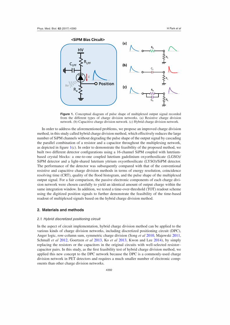
Charge division multiplexing is a well-established technique for reducing the number of output channels of the PET detectors. The resistive charge division method is a conventional method, which results in moderate performance of the detector with a good position decod-ing accuracy (Siegel et al 1996, Olcott et al 2005a, Popov and Majewski 2006). However, multiplexing SiPM signals using the resistive charge division network causes significant resistance–capacitance delay (RC delay) in the scintillation signals, as depicted in figure 1(a), thereby worsening the timing performance of the detector (Ko et al 2015). The capacitive charge division method is an alternative technique, which mitigates the undesirable influence of RC delay by using a minimal number of resistive components throughout the multiplex-ing network (Olcott et al 2005b, Downie et al 2013, Du et al 2013). Although the capacitive charge division method achieves a faster timing performance of the detector, it suffers from an output signal undershoot, as depicted in figure 1(b), causing a degradation of energy perfor-mance and a poor quality of flood histogram.
H Park et alPhys. Med. Biol. 62 (2017) 4390
4392
In order to address the aforementioned problems, we propose an improved charge division method, in this study called hybrid charge division method, which effectively reduces the large number of SiPM channels without degrading the pulse shape of the output signal by cascading the parallel combination of a resistor and a capacitor throughout the multiplexing network, as depicted in figure 1(c). In order to demonstrate the feasibility of the proposed method, we built two different detector configurations using a 16-channel SiPM coupled with lutetium-based crystal blocks: a one-to-one coupled lutetium gadolinium oxyorthosilicate (LGSO)/SiPM detector and a light-shared lutetium yttrium oxyorthosilicate (LYSO)/SiPM detector. The performance of the detector was subsequently compared with that of the conventional resistive and capacitive charge division methods in terms of energy resolution, coincidence resolving time (CRT), quality of the flood histogram, and the pulse shape of the multiplexed output signal. For a fair comparison, the passive electronic components of each charge divi-sion network were chosen carefully to yield an identical amount of output charge within the same integration window. In addition, we tested a time-over-threshold (TOT) readout scheme using the digitized position signals to further demonstrate the feasibility of the time-based readout of multiplexed signals based on the hybrid charge division method.
2. Materials and methods
2.1. Hybrid discretized positioning circuit
In the aspect of circuit implementation, hybrid charge division method can be applied to the various kinds of charge division networks, including discretized positioning circuit (DPC), Anger logic, row-column sum, symmetric charge division (Song et al 2010, Majewski 2011, Schmall et al 2012, Goertzen et al 2013, Ko et al 2013, Kwon and Lee 2014), by simply replacing the resistors or the capacitors in the original circuits with well-selected resistor–capacitor pairs. In this study, as the first feasibility test of hybrid charge division method, we applied this new concept to the DPC network because the DPC is a commonly-used charge division network in PET detectors and requires a much smaller number of electronic comp-onents than other charge division networks.
Figure 1. Conceptual diagram of pulse shape of multiplexed output signal recorded from the different types of charge division networks. (a) Resistive charge division network. (b) Capacitive charge division network. (c) Hybrid charge division network.
H Park et alPhys. Med. Biol. 62 (2017) 4390
4393
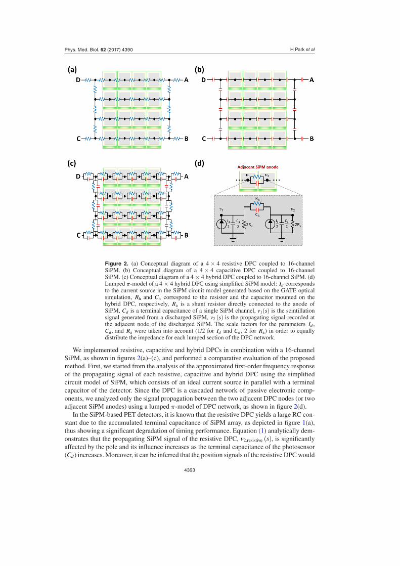
We implemented resistive, capacitive and hybrid DPCs in combination with a 16-channel SiPM, as shown in figures 2(a)–(c), and performed a comparative evaluation of the proposed method. First, we started from the analysis of the approximated first-order frequency response of the propagating signal of each resistive, capacitive and hybrid DPC using the simplified circuit model of SiPM, which consists of an ideal current source in parallel with a terminal capacitor of the detector. Since the DPC is a cascaded network of passive electronic comp-onents, we analyzed only the signal propagation between the two adjacent DPC nodes (or two adjacent SiPM anodes) using a lumped π-model of DPC network, as shown in figure 2(d).
In the SiPM-based PET detectors, it is known that the resistive DPC yields a large RC con-stant due to the accumulated terminal capacitance of SiPM array, as depicted in figure 1(a), thus showing a significant degradation of timing performance. Equation (1) analytically dem-onstrates that the propagating SiPM signal of the resistive DPC, v2.resistive (s), is significantly affected by the pole and its influence increases as the terminal capacitance of the photosensor (Cd) increases. Moreover, it can be inferred that the position signals of the resistive DPC would
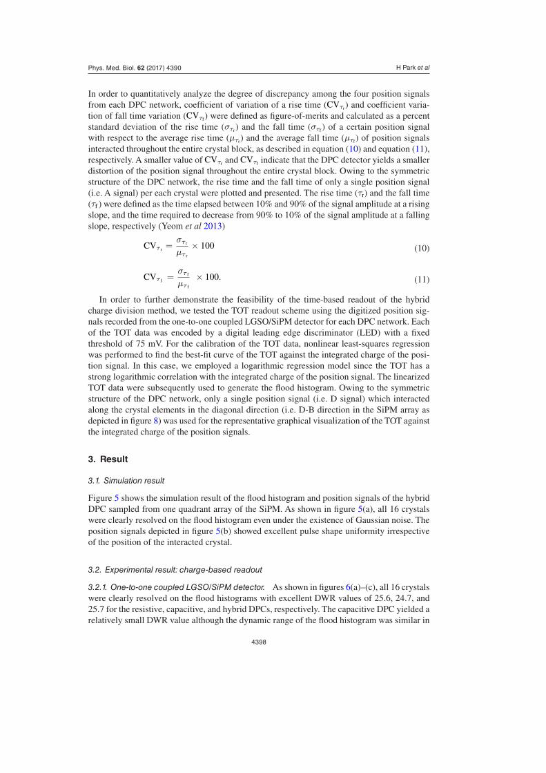
Figure 2. (a) Conceptual diagram of a 4 × 4 resistive DPC coupled to 16-channel SiPM. (b) Conceptual diagram of a 4 × 4 capacitive DPC coupled to 16-channel SiPM. (c) Conceptual diagram of a 4 × 4 hybrid DPC coupled to 16-channel SiPM. (d) Lumped π-model of a 4 × 4 hybrid DPC using simplified SiPM model: Id corresponds to the current source in the SiPM circuit model generated based on the GATE optical simulation, Rh and Ch correspond to the resistor and the capacitor mounted on the hybrid DPC, respectively, Ra is a shunt resistor directly connected to the anode of SiPM, Cd is a terminal capacitance of a single SiPM channel, v1(s) is the scintillation signal generated from a discharged SiPM, v2 (s) is the propagating signal recorded at the adjacent node of the discharged SiPM. The scale factors for the parameters Id , Cd , and Ra were taken into account (1/2 for Id and Cd , 2 for Ra) in order to equally distribute the impedance for each lumped section of the DPC network.
H Park et alPhys. Med. Biol. 62 (2017) 4390
4394
result in a discrepant observation since each position signal undergoes a different amount of RC delay depending on the distance between the discharged SiPM and the readout channel
v2.resistive (s) =
(2Ra ‖ 1
s(Cd/2)
)
Rh +(
2Ra ‖ 1s(Cd/2)
) =2Ra
Rh + 2Ra
[1
1 + s RhRaCdRh+2Ra
]v1(s).
(1)In principle, the DPC can also be implemented using a capacitive mesh, as shown in fig-ure 2(b). Equation (2) analytically demonstrates that the capacitive DPC behaves as a cascaded first-order passive high pass filter; consequently, the propagating SiPM signal, v2.capacitive (s), can preserve high-frequency components while exhibiting the undershoot response inherited from the DC blocking nature of the capacitor, as depicted in figure 1(b). In this regard, the capacitive charge division method could yield a faster timing performance than the resistive method, with slight performance degradation of the signal-to-noise ratio of the multiplexed output signal
v2.capacitive (s) =
(2Ra ‖ 1
s(Cd/2)
)
1sCh
+(
2Ra ‖ 1s(Cd/2)
) =
[s(2RaCh)
1 + s(2RaCh + RaCd)
]v1 (s).
(2)The analytical description of the propagating SiPM signal of the hybrid DPC is shown in equa-tion (3). In our proposed method, if the selected values of the resistor (Rh) and the capacitor (Ch) satisfy the relation given in equation (4), the propagating SiPM signal, v2.hybrid (s), would exhibit excellent pulse shape uniformity, showing identical rise and fall times regardless of the position of the discharged SiPM, as depicted in figure 1(c). In other words, the hybrid charge division method can eliminate the undesirable position-dependent signal distortion observed in the conventional resistive and capacitive charge division methods by cancelling the pole-zero pair of the detector system, as illustrated in equation (5)
v2.hybrid (s) =
(2Ra ‖ 1
s(Cd/2)
)(
Rh ‖ 1sCh
)+
(2Ra ‖ 1
s(Cd/2)
) =2Ra
Rh + 2Ra
[1 + sRhCh
1 + s RhRa(Cd+2Ch)Rh+2Ra
]v1(s)
(3)
RhCh =RhRa(Cd + 2Ch)
Rh + 2Ra (4)
v2.hybrid (s) =2Ra
Rh + 2Rav1(s). (5)
2.2. Simulation study
Based on the above circuit analysis, we performed simulation via the Personal Simulation Program with Integrated Circuit Emphasis (PSPICE; Capture CIS, Cadence Design Systems Inc., US) to investigate the feasibility of the hybrid DPC.
We used the equivalent circuit model of a Hamamatsu SiPM with the terminal capacitance (Cd) of 320 pF to obtain reliable simulation results (Seifert et al 2009, Avella et al 2012). The current source in the SiPM circuit model was generated based on the Geant4 application for tomographic emission (GATE) optical simulation (OpenGATE collaboration, France). The
H Park et alPhys. Med. Biol. 62 (2017) 4390
4395
detector response of the single SiPM channel was obtained by the convolution of the single micro-cell response of the SiPM and the light photon distribution of the lutetium oxyortho-silicate (LSO) crystal.
We repeated the simulation with various different sets of Rh and Ch pairs that satisfy the equation (4) until we could find the most preferable condition for a fair comparison between the conventional and the proposed methods. The shunt resistor (Ra) in the bias circuit was carefully chosen not to yield a large amount of charge loss from the anode of the SiPM to the ground. Owing to the symmetrical structure of the DPC network, the position signals from only one quadrant of the SiPM array were sampled and examined. Gaussian noise with a standard deviation of 2 mV (i.e. similar to the value observed in a real measurement) was added to each position signal. The flood histogram was generated using the position decod-ing logic, as described in equations (6) and (7), where QA, QB, QC , and QD correspond to the amount of output charge collected from each position signal A, B, C, and D, respectively
X =QA + QB − QC − QD
QA + QB + QC + QD (6)
Y =QA − QB − QC + QD
QA + QB + QC + QD. (7)
2.3. Detector configurations
The performance of the DPC detector was tested using two different configurations: the one-to-one coupled LGSO/SiPM detector and the light-shared LYSO/SiPM detector. In the for-mer configuration, a 16-channel old version of Hamamatsu SiPM (S11064-050P; Hamamatsu Photonics K.K., Japan) was coupled with a 4 × 4 array of 3 × 3 × 20 mm3 LGSO crystal block (Lu1.9Gd0.1SiO4(Ce); Hitachi Chemical, Japan), whereas in the latter configuration, a 9 × 9 array of 1.2 × 1.2 × 10 mm3 LYSO crystal block (Lu1.8Y0.2SiO5(Ce); SIPAT, China) was coupled to the abovementioned SiPM using a 1.85 mm thick PVC light guide. In order to maximize the efficiency of the light collection, all the crystals were wrapped with a 0.065 mm thick enhanced spectral reflector (ESR; 3M, US) and both the crystal blocks were tightly coupled using an optical grease (BC-630; OKEN, Japan) with a refractive index of 1.465.
2.4. Measurement setup and data acquisition
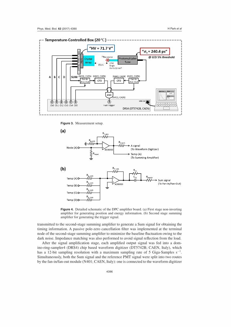
Figure 3 shows the measurement setup used in this study. The experiments were conducted inside a temperature-controlled box at 20 °C. The bias voltage supplied to the SiPM was 71.7 V (with an overvoltage of approximately 2.0 V). We used a reference detector consist-ing of Hamamatsu R9800 PMT and an ESR-wrapped single 4 × 4 × 10 mm3 LYSO crystal to acquire the coincidence data. The single timing resolution of the reference detector was 240.4 ps, which was measured using the system described by Lee et al (2011). A 22Na point source (15 µCi) with a diameter of 0.25 mm was deployed in front of the reference detector to irradiate the opposite detector uniformly with a sufficiently large solid angle. The distance between the two detectors was 15 cm.
Figure 4 illustrates a detailed schematic of the DPC amplifier board. The output sig-nals from the DPC network were processed using high-speed current feedback amplifiers (AD8000; Analog Device, US). The input impedance of the amplifier was chosen to be 50 Ω. The multiplexed output signals (i.e. from the nodes A, B, C, and D) were initially amplified to obtain the energy and position information, and the four amplified signals were subsequently
H Park et alPhys. Med. Biol. 62 (2017) 4390
4396
transmitted to the second-stage summing amplifier to generate a Sum signal for obtaining the timing information. A passive pole-zero cancellation filter was implemented at the terminal node of the second-stage summing amplifier to minimize the baseline fluctuation owing to the dark noise. Impedance matching was also performed to avoid signal reflection from the load.
After the signal amplification stage, each amplified output signal was fed into a dom-ino-ring-sampler4 (DRS4) chip based waveform digitizer (DT5742B; CAEN, Italy), which has a 12-bit sampling resolution with a maximum sampling rate of 5 Giga-Samples s−1. Simultaneously, both the Sum signal and the reference PMT signal were split into two routes by the fan-in/fan-out module (N401; CAEN, Italy): one is connected to the waveform digitizer
Figure 3. Measurement setup.
Figure 4. Detailed schematic of the DPC amplifier board. (a) First stage non-inverting amplifier for generating position and energy information. (b) Second stage summing amplifier for generating the trigger signal.
H Park et alPhys. Med. Biol. 62 (2017) 4390
4397
for the time pick-off, and the other is connected to the constant fraction discriminator (CFD) modules (N843; CAEN, Italy) for generating trigger signals. The digital outputs generated by each CFD nuclear instrumentation module (NIM) were subsequently fed into the AND NIM (N455; CAEN, Italy) for coincidence detection. The coincidence window was set as 20 ns. The coincidence digital output from the AND NIM was connected to the fast trigger port of the waveform digitizer. All the digitized signals from the waveform digitizer were transmitted through a universal serial bus (USB) 2.0 cable to a personal computer for data analysis.
2.5. Data analysis and performance evaluation
The performance of the hybrid DPC detector was investigated via a comparison study with the resistive and capacitive DPCs. For a fair comparison, the passive electronic components in each DPC network were chosen based on the results of the simulation study to yield an identi-cal amount of output charge within the same integration window.
In order to show the multiplexed output signals recorded from each DPC network, the rep-resentative pulse shapes of position signals (i.e. A, B, C, and D) were sampled from the corner and the center crystals at a rate of 1 Giga-Samples s−1. Only 100 events within the 1% energy window at photopeak were included and averaged to exclusively visualize the pulse shape of the 511 keV scintillation signal.
The quality of the flood histogram, energy resolution, and CRT were measured for each crystal element in order to evaluate the performance of the detector. As a quality parameter of the flood histogram, the distance-to-width ratio (DWR) was calculated as the average ratio between the distance of the adjacent peaks on the flood histogram and the average full width at half maximum (FWHM) value of the peaks, as described in equation (8) (Won et al 2016). In the equation (8), xi, xj and yi, yj correspond to the position of the ith and jth adjacent crystal pairs along the horizontal axis (x-axis) and the vertical axis (y-axis) on the flood histogram, respectively. wx,i, wx,j and wy,i, wy,j are the FWHM values of 1D projection profiles along the x- and y-axis of the ith and jth crystal, respectively. Nadj is the total number of adjacent crystal pairs
DWR =1
Nadj
Nadj∑i,j∈(adj pair)
(|xi − xj|
(wx,i + wx,j)/2+
|yi − yj|(wy,i + wy,j)/2
). (8)
In order to calculate the energy resolution, the total amount of output charge was estimated by summing the integrated charge of each position signal. The charge integration was per-formed during an interval of 150 ns. The event-by-event baseline correction was done using the mean value of 30 data points before the onset of the signal.
In the timing measurement, only the events within the energy window of full width at tenth maximum (FWTM) at 511 keV photopeak were taken into account. The arrival time of the incident gamma photon was picked off from the Sum signal by using the digital CFD with a threshold level of 5% (i.e. 5% of peak amplitude of each Sum signal). Each Sum signal was oversampled (×10) using cubic spline interpolation to minimize the quantization error. The CRT of the DPC detectors was subsequently calculated by quadratically subtracting the single time resolution of the reference detector (δtRef ) from the CRT between the DPC and reference detectors (∆ tDPC/Ref) and multiplying the result with
√2, as described in equation (9) (Ko
and Lee 2015)
CRT =√
2 ·√∆t2
DPC/Ref − δt2Ref . (9)
H Park et alPhys. Med. Biol. 62 (2017) 4390
4398
In order to quantitatively analyze the degree of discrepancy among the four position signals from each DPC network, coefficient of variation of a rise time (CVτr) and coefficient varia-tion of fall time variation (CVτf) were defined as figure-of-merits and calculated as a percent standard deviation of the rise time (στr ) and the fall time (στf ) of a certain position signal with respect to the average rise time (µτr) and the average fall time (µτf) of position signals interacted throughout the entire crystal block, as described in equation (10) and equation (11), respectively. A smaller value of CVτr and CVτf indicate that the DPC detector yields a smaller distortion of the position signal throughout the entire crystal block. Owing to the symmetric structure of the DPC network, the rise time and the fall time of only a single position signal (i.e. A signal) per each crystal were plotted and presented. The rise time (τr) and the fall time (τf ) were defined as the time elapsed between 10% and 90% of the signal amplitude at a rising slope, and the time required to decrease from 90% to 10% of the signal amplitude at a falling slope, respectively (Yeom et al 2013)
CVτ r =στ r
µτ r
× 100 (10)
CVτ f =στ f
µτ f
× 100. (11)
In order to further demonstrate the feasibility of the time-based readout of the hybrid charge division method, we tested the TOT readout scheme using the digitized position sig-nals recorded from the one-to-one coupled LGSO/SiPM detector for each DPC network. Each of the TOT data was encoded by a digital leading edge discriminator (LED) with a fixed threshold of 75 mV. For the calibration of the TOT data, nonlinear least-squares regression was performed to find the best-fit curve of the TOT against the integrated charge of the posi-tion signal. In this case, we employed a logarithmic regression model since the TOT has a strong logarithmic correlation with the integrated charge of the position signal. The linearized TOT data were subsequently used to generate the flood histogram. Owing to the symmetric structure of the DPC network, only a single position signal (i.e. D signal) which interacted along the crystal elements in the diagonal direction (i.e. D-B direction in the SiPM array as depicted in figure 8) was used for the representative graphical visualization of the TOT against the integrated charge of the position signals.
3. Result
3.1. Simulation result
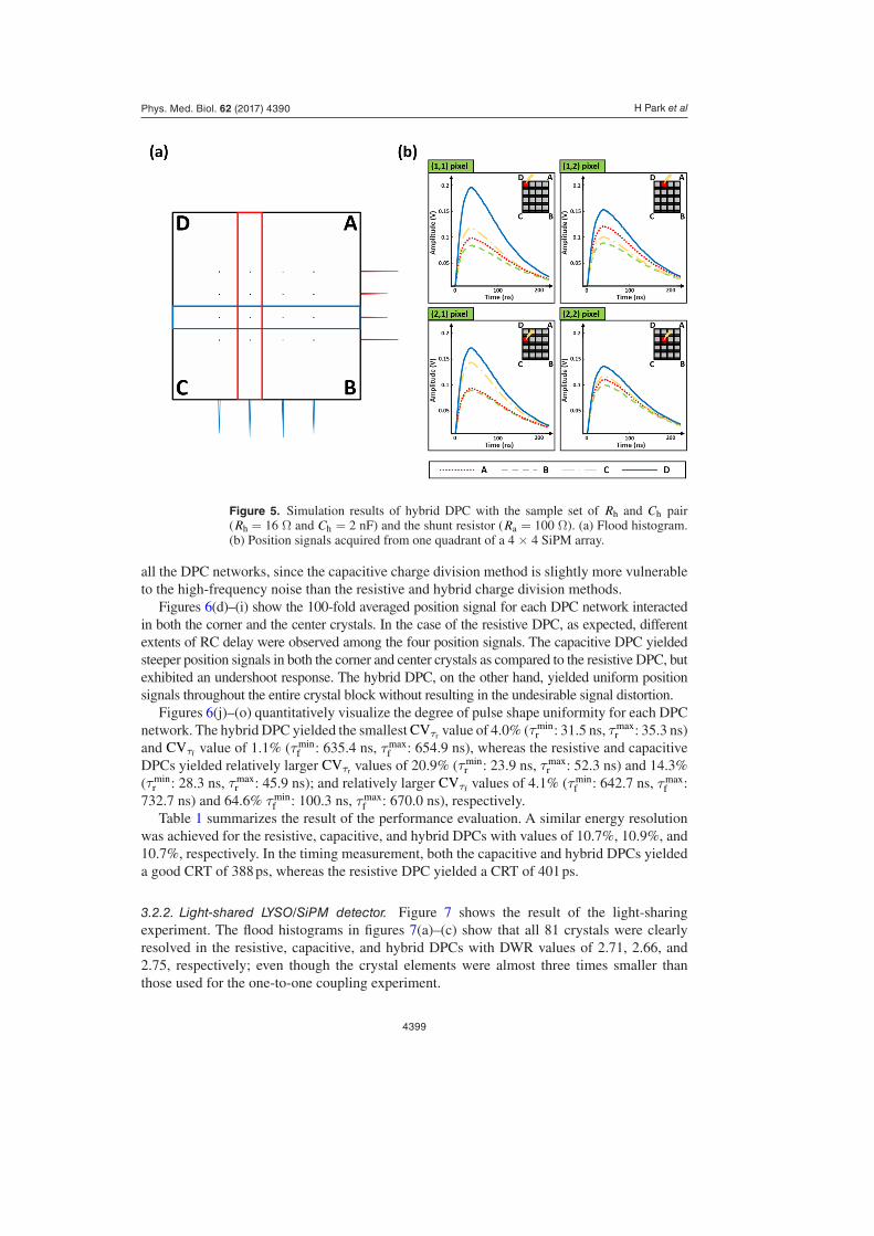
Figure 5 shows the simulation result of the flood histogram and position signals of the hybrid DPC sampled from one quadrant array of the SiPM. As shown in figure 5(a), all 16 crystals were clearly resolved on the flood histogram even under the existence of Gaussian noise. The position signals depicted in figure 5(b) showed excellent pulse shape uniformity irrespective of the position of the interacted crystal.
3.2. Experimental result: charge-based readout
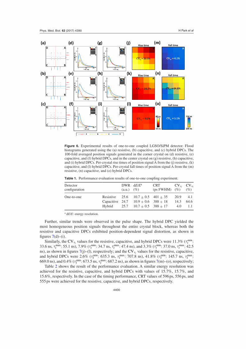
3.2.1. One-to-one coupled LGSO/SiPM detector. As shown in figures 6(a)–(c), all 16 crystals were clearly resolved on the flood histograms with excellent DWR values of 25.6, 24.7, and 25.7 for the resistive, capacitive, and hybrid DPCs, respectively. The capacitive DPC yielded a relatively small DWR value although the dynamic range of the flood histogram was similar in
H Park et alPhys. Med. Biol. 62 (2017) 4390
4399
all the DPC networks, since the capacitive charge division method is slightly more vulnerable to the high-frequency noise than the resistive and hybrid charge division methods.
Figures 6(d)–(i) show the 100-fold averaged position signal for each DPC network interacted in both the corner and the center crystals. In the case of the resistive DPC, as expected, different extents of RC delay were observed among the four position signals. The capacitive DPC yielded steeper position signals in both the corner and center crystals as compared to the resistive DPC, but exhibited an undershoot response. The hybrid DPC, on the other hand, yielded uniform position signals throughout the entire crystal block without resulting in the undesirable signal distortion.
Figures 6(j)–(o) quantitatively visualize the degree of pulse shape uniformity for each DPC network. The hybrid DPC yielded the smallest CVτr value of 4.0% (τmin
r : 31.5 ns, τmaxr : 35.3 ns)
and CVτf value of 1.1% (τminf : 635.4 ns, τmax
f : 654.9 ns), whereas the resistive and capacitive DPCs yielded relatively larger CVτr values of 20.9% (τmin
r : 23.9 ns, τmaxr : 52.3 ns) and 14.3%
(τminr : 28.3 ns, τmax
r : 45.9 ns); and relatively larger CVτf values of 4.1% (τminf : 642.7 ns, τmax
f : 732.7 ns) and 64.6% τmin
f : 100.3 ns, τmaxf : 670.0 ns), respectively.
Table 1 summarizes the result of the performance evaluation. A similar energy resolution was achieved for the resistive, capacitive, and hybrid DPCs with values of 10.7%, 10.9%, and 10.7%, respectively. In the timing measurement, both the capacitive and hybrid DPCs yielded a good CRT of 388 ps, whereas the resistive DPC yielded a CRT of 401 ps.
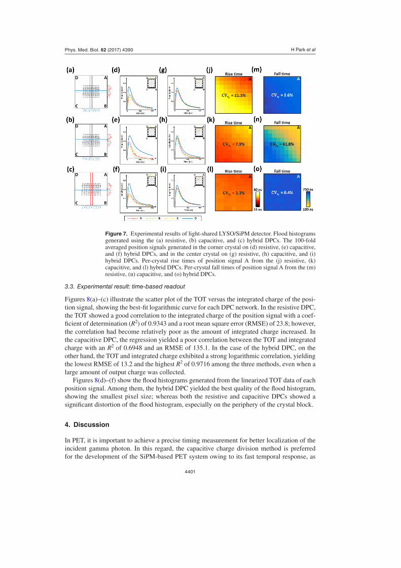
3.2.2. Light-shared LYSO/SiPM detector. Figure 7 shows the result of the light-sharing experiment. The flood histograms in figures 7(a)–(c) show that all 81 crystals were clearly resolved in the resistive, capacitive, and hybrid DPCs with DWR values of 2.71, 2.66, and 2.75, respectively; even though the crystal elements were almost three times smaller than those used for the one-to-one coupling experiment.
Figure 5. Simulation results of hybrid DPC with the sample set of Rh and Ch pair (Rh = 16 Ω and Ch = 2 nF) and the shunt resistor (Ra = 100 Ω). (a) Flood histogram. (b) Position signals acquired from one quadrant of a 4 × 4 SiPM array.
H Park et alPhys. Med. Biol. 62 (2017) 4390
4400
Further, similar trends were observed in the pulse shape. The hybrid DPC yielded the most homogeneous position signals throughout the entire crystal block, whereas both the resistive and capacitive DPCs exhibited position-dependent signal distortion, as shown in figures 7(d)–(i).
Similarly, the CVτr values for the resistive, capacitive, and hybrid DPCs were 11.3% (τminr :
33.6 ns, τmaxr : 55.1 ns), 7.9% (τmin
r : 34.7 ns, τmaxr : 47.4 ns), and 3.3% (τmin
r : 37.0 ns, τmaxr : 42.5
ns), as shown in figures 7(j)–(l), respectively; and the CVτr values for the resistive, capacitive, and hybrid DPCs were 2.6% (τmin
f : 635.3 ns, τmaxf : 707.8 ns), 41.8% (τmin
f : 145.7 ns, τmaxf :
669.0 ns), and 0.4% (τminf : 673.5 ns, τmax
f : 687.2 ns), as shown in figures 7(m)–(o), respectively;Table 2 shows the result of the performance evaluation. A similar energy resolution was
achieved for the resistive, capacitive, and hybrid DPCs with values of 15.7%, 15.7%, and 15.6%, respectively. In the case of the timing performance, CRT values of 596 ps, 556 ps, and 555 ps were achieved for the resistive, capacitive, and hybrid DPCs, respectively.
Figure 6. Experimental results of one-to-one coupled LGSO/SiPM detector. Flood histograms generated using the (a) resistive, (b) capacitive, and (c) hybrid DPCs. The 100-fold averaged position signals generated in the corner crystal on (d) resistive, (e) capacitive, and (f) hybrid DPCs, and in the center crystal on (g) resistive, (h) capacitive, and (i) hybrid DPCs. Per-crystal rise times of position signal A from the (j) resistive, (k) capacitive, and (l) hybrid DPCs. Per-crystal fall times of position signal A from the (m) resistive, (n) capacitive, and (o) hybrid DPCs.
Table 1. Performance evaluation results of one-to-one coupling experiment.
Detector configuration
DWR (a.u.)
dE/Ea (%)
CRT (ps FWHM)
CVτr (%)
CVτf (%)
One-to-one Resistive 25.6 10.7 ± 0.5 401 ± 35 20.9 4.1Capacitive 24.7 10.9 ± 0.6 388 ± 18 14.3 64.6Hybrid 25.7 10.7 ± 0.5 388 ± 17 4.0 1.1
a dE/E: energy resolution.
H Park et alPhys. Med. Biol. 62 (2017) 4390
4401
3.3. Experimental result: time-based readout
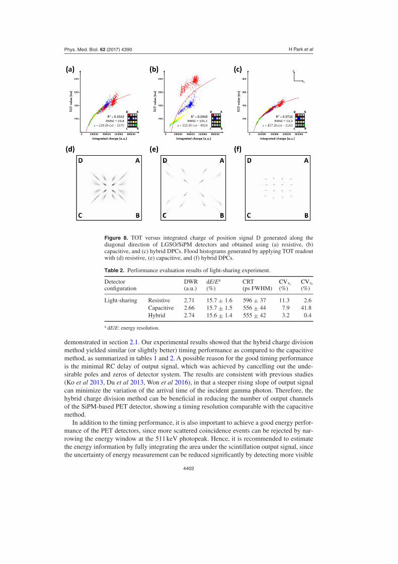
Figures 8(a)–(c) illustrate the scatter plot of the TOT versus the integrated charge of the posi-tion signal, showing the best-fit logarithmic curve for each DPC network. In the resistive DPC, the TOT showed a good correlation to the integrated charge of the position signal with a coef-ficient of determination (R2) of 0.9343 and a root mean square error (RMSE) of 23.8; however, the correlation had become relatively poor as the amount of integrated charge increased. In the capacitive DPC, the regression yielded a poor correlation between the TOT and integrated charge with an R2 of 0.6948 and an RMSE of 135.1. In the case of the hybrid DPC, on the other hand, the TOT and integrated charge exhibited a strong logarithmic correlation, yielding the lowest RMSE of 13.2 and the highest R2 of 0.9716 among the three methods, even when a large amount of output charge was collected.
Figures 8(d)–(f) show the flood histograms generated from the linearized TOT data of each position signal. Among them, the hybrid DPC yielded the best quality of the flood histogram, showing the smallest pixel size; whereas both the resistive and capacitive DPCs showed a significant distortion of the flood histogram, especially on the periphery of the crystal block.
4. Discussion
In PET, it is important to achieve a precise timing measurement for better localization of the incident gamma photon. In this regard, the capacitive charge division method is preferred for the development of the SiPM-based PET system owing to its fast temporal response, as
Figure 7. Experimental results of light-shared LYSO/SiPM detector. Flood histograms generated using the (a) resistive, (b) capacitive, and (c) hybrid DPCs. The 100-fold averaged position signals generated in the corner crystal on (d) resistive, (e) capacitive, and (f) hybrid DPCs, and in the center crystal on (g) resistive, (h) capacitive, and (i) hybrid DPCs. Per-crystal rise times of position signal A from the (j) resistive, (k) capacitive, and (l) hybrid DPCs. Per-crystal fall times of position signal A from the (m) resistive, (n) capacitive, and (o) hybrid DPCs.
H Park et alPhys. Med. Biol. 62 (2017) 4390
4402
demonstrated in section 2.1. Our experimental results showed that the hybrid charge division method yielded similar (or slightly better) timing performance as compared to the capacitive method, as summarized in tables 1 and 2. A possible reason for the good timing performance is the minimal RC delay of output signal, which was achieved by cancelling out the unde-sirable poles and zeros of detector system. The results are consistent with previous studies (Ko et al 2013, Du et al 2013, Won et al 2016), in that a steeper rising slope of output signal can minimize the variation of the arrival time of the incident gamma photon. Therefore, the hybrid charge division method can be beneficial in reducing the number of output channels of the SiPM-based PET detector, showing a timing resolution comparable with the capacitive method.
In addition to the timing performance, it is also important to achieve a good energy perfor-mance of the PET detectors, since more scattered coincidence events can be rejected by nar-rowing the energy window at the 511 keV photopeak. Hence, it is recommended to estimate the energy information by fully integrating the area under the scintillation output signal, since the uncertainty of energy measurement can be reduced significantly by detecting more visible
Table 2. Performance evaluation results of light-sharing experiment.
Detector configuration
DWR (a.u.)
dE/Ea (%)
CRT (ps FWHM)
CVτr (%)
CVτf (%)
Light-sharing Resistive 2.71 15.7 ± 1.6 596 ± 37 11.3 2.6Capacitive 2.66 15.7 ± 1.5 556 ± 44 7.9 41.8Hybrid 2.74 15.6 ± 1.4 555 ± 42 3.2 0.4
a dE/E: energy resolution.
Figure 8. TOT versus integrated charge of position signal D generated along the diagonal direction of LGSO/SiPM detectors and obtained using (a) resistive, (b) capacitive, and (c) hybrid DPCs. Flood histograms generated by applying TOT readout with (d) resistive, (e) capacitive, and (f) hybrid DPCs.
H Park et alPhys. Med. Biol. 62 (2017) 4390
4403
photons produced from the scintillation crystal. Therefore, in terms of the statistical error, it is expected that the resistive and hybrid charge division methods would yield more accurate energy measurements with little loss of charge information; in other words, the capacitive charge division method would result in the degradation of energy resolution as the width of integration window increases due to the negative charge integration caused by the undershoot response. However, in this study, the capacitive DPC yielded energy resolution comparable to both the resistive and hybrid DPCs, since the integration window was narrow enough (i.e. 150 ns) to avoid the negative charge integration from the capacitive DPC.
The charge-based readout requires an analog-to-digital converter (ADC) and a subsequent signal processing device to obtain the energy information of detected scintillation signal; and therefore, it usually demands a large amount of resource-heavy electronics and causes significant power consumption and heat dissipation. In this regard, time-based readout based on a counter or a time-to-digital conveter (TDC) can be a cost-effective alternative because it enables a highly-integrated signal readout by simplifying the front-end and back-end electronics of PET system without the requirement of ADC. Conventionally, the charge division multiplexing method was not regarded as an eligible candidate for the time-based readout. Figures 8(a) and (b) demonstrate the imperfect calibration of the TOT data acquired from the conventional resistive and capacitive charge division methods, resulting in blurring and distortion of the flood histogram. In order to achieve the best performance of the time-based readout, therefore, it is important to obtain a uni-form pulse shape of output signal from the multiplexing network so that the TOT highly correlates to the energy of detected photon. The proposed hybrid charge division method showed a strong correlation between the TOT and integrated charge of the position signal owing to its excellent pulse shape uniformity, as shown in figure 8(c); accordingly, the linearity calibration of TOT data can be performed by simple logarithmic regression, showing better quality of the flood histogram as compared with the conventional charge division methods as shown in figure 8(f). As a result, the hybrid charge division method can be useful for enhancing the performance of the time-based readout in terms of the linearity and calibration simplicity of the energy.
5. Summary and conclusion
In this study, we introduced the concept and demonstrated the feasibility of the hybrid charge division method using the DPC network. The simulation and experimental results were prom-ising in that the hybrid charge division method yielded good performance in terms of energy and timing, inheriting only the advantages of the resistive and capacitive charge division meth-ods. Moreover, the hybrid charge division method showed excellent pulse shape uniformity that does not depend on the position of the interacted crystal, and an outstanding feasibility for the time-based readout. Therefore, we can conclude that the hybrid charge division method is useful for effectively reducing the number of output channels of the SiPM array.
Acknowledgments
This work was supported by grants from the National Research Foundation of Korea (NRF) funded by the Korean Ministry of Science, ICT and Future Planning (grant no. NRF-2014M3C7034000 and NRF-2016R1A2B3014645), and the Korea Health Technology R&D Project through the Korea Health Industry Development Institute (KHIDI), funded by the Ministry of Health & Welfare, Republic of Korea (grant no. HI14C1135).
H Park et alPhys. Med. Biol. 62 (2017) 4390
4404
References
Anghinolfi F, Jarron P, Krummenacher F, Usenko E and Williams M C S 2004 NINO: an ultrafast low-power front-end amplifier discriminator for the time-of-flight detector in the ALICE experiment IEEE Trans. Nucl. Sci. 51 1974–8
Avella P, Santo D A, Lohstroh A, Sajjad M T and Sallin P J 2012 A study of timing properties of silicon photomultipliers Nucl. Instrum. Meth. Phys. Res. A 695 257–60
Cates J W and Levin C S 2016 Advances in coincidence time resolution for PET Phys. Med. Biol. 61 2255–64
Conti M 2011 Focus on time-of-flight PET: the benefits of improved time resolution Eur. J. Nucl. Med. Mol. Imaging. 38 1147–57
Corsi F, Foresta M, Marzocca C, Matarrese G and Guerra D A 2009 BASIC: an 8-channel front-end ASIC for silicon photomultiplier detector IEEE Nuclear Science Symp. Conf. Record pp 1082–7
Downie E, Yang X and Peng H 2013 Investigation of analog charge multiplexing schemes for SiPM based PET block detectors Phys. Med. Biol. 58 3943–64
Du J, Schmall J P, Yang Y, Di K, Dokhale P A, Shah K S and Cherry S R 2013 A simple capacitive charge-division readout for position-sensitive solid-state photomultiplier arrays IEEE Trans. Nucl. Sci. 60 3188–97
Fischer P, Peric I, Ritzert M and Koniczek M 2009 Fast self triggered multi channel readout ASIC for time- and energy measurement IEEE Trans. Nucl. Sci. 56 1153–8
Goertzen A L, Zhang X and McClarty M M 2013 Design and performance of a resistor multiplexing readout circuit for a SiPM detector IEEE Trans. Nucl. Sci. 60 1541–9
Grant A M, Deller T W, Khalighi M M, Maramraju S H, Delso G and Levin C S 2016 NEMA NU 2-2012 performance studies for the SiPM-based ToF-PET component of the GE SIGNA PET/MR system Med. Phys. 43 2334
Hong S J, Kang H G, Ko G B, Song I C, Rhee J T and Lee J S 2012 SiPM-PET with a short optical fiber bundle for simultaneous PET-MR imaging Phys. Med. Biol. 57 3869–83
Ko G B and Lee J S 2015 Performance characterization of high quantum efficiency metal package photomultiplier tubes for time-of-flight and high-resolution PET applications Med. Phys. 42 510–20
Ko G B et al 2016 Simultaneous multi-parametric PET/MRI with silicon photomultiplier PET and ultra-high field MRI for small animal imaging J. Nucl. Med. 57 1309–15
Ko G B, Yoon H S, Kwon S I, Lee C M, Ito M Hong S J, Lee D S and Lee J S 2013 Development of a front-end analog circuit for multi-channel SiPM readout and performance verification for various PET detector designs Nucl. Instrum. Meth. Phys. Res. A 703 38–44
Kwon S I and Lee J S 2014 Signal encoding method for a time-of-flight PET detector using a silicon photomultiplier array Nucl. Instrum. Meth. Phys. Res. A 761 39–45
Kwon S I et al 2011 Development of small-animal pet prototype using silicon photomultiplier (SiPM): initial results of phantom and animal imaging studies J. Nucl. Med. 52 572–9
Lee J P, Ito M and Lee J S 2011 Evaluation of a fast photomultiplier tube for time-of-flight PET Biomed. Eng. Lett. 1 174–9
Lee J S 2015 Innovative physics and engineering research in nuclear medicine and molecular imaging: a message from the associate editor Nucl. Med. Mol. Imaging. 49 249–50
Lee J S and Hong S J 2010 Geiger-mode avalanche photodiodes for PET/MRI Electronic Circuits for Radiation Detection ed K Iniewski (Boca Raton, FL: CRC Press)
Lee M S and Lee J S 2015 Depth-of-interaction measurement in a single-layer crystal array with a single-ended readout using digital silicon photomultiplier Phys. Med. Biol. 60 6495–514
Majewski S, Proffitt J, Stolin A and Raylman R 2011 Development of a ‘resistive’ readout for SiPM arrays IEEE Nuclear Science Symp. Conf. Record pp 3939–44
Moses W W 2007 Recent advances and future advances in time-of-flight PET Nucl. Instrum. Meth. Phys. Res. A 580 919–24
Nemallapudi M V, Gundacker S, Lecoq P, Auffray E, Ferri A, Gola A and Piemonte C 2015 Sub-100 ps coincidence time resolution for positron emission tomography with LSO:Ce codoped with Ca Phys. Med. Biol. 60 4635–49
Olcott P D, Habte F, Zhang J and Levin C S 2005a Charge multiplexing readout for position sensitive avalanche photodiodes IEEE Nuclear Science Symp. Conf. Record pp 2935–7
H Park et alPhys. Med. Biol. 62 (2017) 4390
4405
Olcott P D, Talcott J A, Levin C S, Habte F and Foudray A M 2005b Compact readout electronics for position sensitive photomultiplier tubes IEEE Trans. Nucl. Sci. 52 21–7
Popov V and Majewski S 2003 Readout electronics for multianode photomultiplier tubes with pad matrix anode layout IEEE Nuclear Science Symp. Conf. Record pp 2156–9
Rolo M D, Bugalho R, Gonçalves F, Mazza G, Rivetti A, Silva J C, Silva R and Varela J 2013 TOFPET ASIC for PET applications J. Instrum. 8 C02050
Roncali E and Cherry S R 2011 Application of silicon photomultipliers to positron emission tomography Ann. Biomed. Eng. 39 1358–77
Schaart D R, Seifert S, Vinke R, van Dam H T, Dendooven P, Lohner H and Beekman F J 2010 LaBr3:Ce and SiPMs for time-of-flight PET: achieving 100 ps coincidence resolving time Phys. Med. Biol. 55 N179–89
Schmall J P, Du J, Yang Y, Dokhale P A, McClish M, Christian J, Shah K S and Cherry S R 2012 Comparison of large-area position-sensitive solid-state photomultipliers for small animal PET Phys. Med. Biol. 57 8119–34
Shen W, Briggl K, Chen H, Fischer P, Gil A, Harion T, Ritzert M and Schultz-Coulon H-C 2012 STiC—a mixed mode chip for SiPM ToF applications IEEE Nuclear Science Symp. and Medical Imaging Conf. Record pp 877–81
Siegel S, Silverman R W, Shao Y and Cherry S R 1996 Simple charge division readouts for imaging scintillator arrays using a multi-channel PMT IEEE Trans. Nucl. Sci. 43 1634–41
Seifert S, van Dam H T, Huizenga J, Vinke R, Dendooven P, Lohner H and Schaart D R 2009 Simulation of silicon photomultiplier signals IEEE Trans. Nucl. Sci. 56 3726–33
Son J-W, Ko G B, Won J Y, Yoon H S and Lee J S 2016 Development and performance evaluation of a time-of-flight positron emission tomography detector based on a high-quantum-efficiency-multi-anode photomultiplier tube IEEE Trans. Nucl. Sci. 63 44–51
Song T Y, Wu H, Komarov S, Siegel S B and Tai Y C 2010 A sub-millimeter resolution PET detector module using a multi-pixel photon counter array Phys. Med. Biol. 55 2573–87
Surti S and Karp J S 2016 Advances in time-of-flight PET Phys. Medica. 32 12–22Ullah M N, Pratiwi E, Cheon J, Choi H and Yeom J Y 2016 Instrumentation for time-of-flight positron
emission tomography Nucl. Med. Mol. Imaging. 50 112–22Won J Y, Ko G B and Lee J S 2016 Delay grid multiplexing: simple time-based multiplexing and readout
method for silicon photomultipliers Phys. Med. Biol. 61 7113–35Yamamoto S, Watabe T, Watabe H, Aoki M, Sugiyama E, Imaizumi M, Kanai Y, Shimosegawa E and
Hatazawa J 2012 Simultaneous imaging using Si-PM-based PET and MRI for development of an integrated PET/MRI system Phys. Med. Biol. 57 N1–13
Yeom J Y, Vinke R, Pavlov N, Bellis S, Wall L, O’Neill K, Jackson C and Levin C S 2013 Fast timing silicon photomultipliers for scintillation detectors IEEE Photon. Technol. Lett. 25 1309–12
Yoon H S, Ko G B, Kwon S I, Lee C M, Ito M, Song I C, Lee D S, Hong S J and Lee J S 2012 Initial results of simultaneous PET/MRI experiments with an MR-compatible silicon photomultiplier PET scanner J. Nucl. Med. 53 608–14
H Park et alPhys. Med. Biol. 62 (2017) 4390