Embed Size (px)
Citation preview
K220LSMobile Directional Control ValveProportional, Load Sensing, Pre-compensated
2 Parker HannifinMobile Controls Division EuropeBorås, Sweden
Mobile Directional Control ValveK220LS
Catalogue HY17-8537/UK
Catalogue layoutThis catalogue has been designed to give a brief overview of K220LS valves, and to make it easy for you to study and choose from the different options available, so that we may customize your valve in accordance with your wishes. In addition to general information and basic technical data, the catalogue there-fore contains descriptions of the options available for various so-called “function areas” of the valve.
Each function area is given as a subheading, followed by a brief description. When options are available for a function area, the subheading is followed by an “Item number” in brackets, e.g. Pressure relief valve [16]. This is followed by a series of coded options, e.g. PA1, Y1, together with a brief description of what each code represents. Alternatively, one or more pressure, flow or voltage options are given.
Please note that, unless stated otherwise, all sections and views of the valves have been drawn as seen from the inlet section.
How to order your valveThe K220LS directional control valve can be easily specified using Parker computer programme. This means the customer can optimise his valve specification to give the best performance for his application and specific hydraulic system.
Once the demands placed on each individual function have been specified the computer will select the valve design required to give optimum performance. The computer also produces complete documentation for your valve, in the form of a detailed specification and hydraulic circuit diagram.
The computer also generates a unique identification number for each valve type and customer. The number is then stamped into the I.D. plate of each valve. The specification of your valve is then recorded by Parker, so that exact identification of the product can be made at any time in the future to facilitate repeat ordering or servicing.
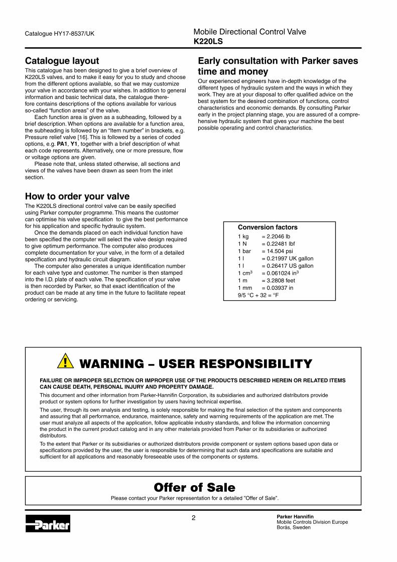
Conversion factors1 kg = 2.2046 lb1 N = 0.22481 lbf1 bar = 14.504 psi1 l = 0.21997 UK gallon1 l = 0.26417 US gallon1 cm3 = 0.061024 in3
1 m = 3.2808 feet1 mm = 0.03937 in9/5 °C + 32 = °F
Early consultation with Parker saves time and moneyOur experienced engineers have in-depth knowledge of the different types of hydraulic system and the ways in which they work. They are at your disposal to offer qualified advice on the best system for the desired combination of functions, control characteristics and economic demands. By consulting Parker early in the project planning stage, you are assured of a compre-hensive hydraulic system that gives your machine the best possible operating and control characteristics.
FAILURE OR IMPROPER SELECTION OR IMPROPER USE OF THE PRODUCTS DESCRIBED HEREIN OR RELATED ITEMS CAN CAUSE DEATH, PERSONAL INJURY AND PROPERTY DAMAGE.
This document and other information from Parker-Hannifin Corporation, its subsidiaries and authorized distributors provide product or system options for further investigation by users having technical expertise.
The user, through its own analysis and testing, is solely responsible for making the final selection of the system and components and assuring that all performance, endurance, maintenance, safety and warning requirements of the application are met. The user must analyze all aspects of the application, follow applicable industry standards, and follow the information concerning the product in the current product catalog and in any other materials provided from Parker or its subsidiaries or authorized distributors.
To the extent that Parker or its subsidiaries or authorized distributors provide component or system options based upon data or specifications provided by the user, the user is responsible for determining that such data and specifications are suitable and sufficient for all applications and reasonably foreseeable uses of the components or systems.
Offer of SalePlease contact your Parker representation for a detailed ”Offer of Sale”.
WARNING – USER RESPONSIBILITY
3 Parker HannifinMobile Controls Division EuropeBorås, Sweden
Mobile Directional Control ValveK220LS
Catalogue HY17-8537/UK
Contents Page
General Information ...................................................................................4Technical Data ...........................................................................................5Inlet Section ...............................................................................................7Spool Section ............................................................................................8Connections [04] and [47] .........................................................................8Mid-inlet section [90-99] ............................................................................8Pressure compensator and/or load-hold check valve [66] .........................9Feed reducer valve [75] .............................................................................9Dimensional Drawings .............................................................................10
[00] refers to item numbers in the customer specification.
Contents
4 Parker HannifinMobile Controls Division EuropeBorås, Sweden
Mobile Directional Control ValveK220LS
Catalogue HY17-8537/UK
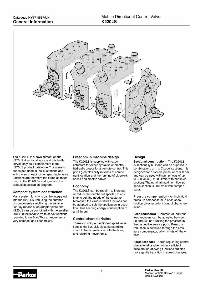
The K220LS is a development of our K170LS directional valve and this leaflet serves only as a complement to the K170LS product catalogue. The numeric codes [00] used in the illustrations and with the sub-headings for specifiable valve functions are therefore the same as those used in the K170LS catalogue and the product specification program.
Compact system constructionMany system functions can be integrated into the K220LS, reducing the number of components simplifying the installa-tion. By means of an adapter plate, the K220LS can be combined with the smaller L90LS directional valve to serve functions requiring lower flow. This arrangement is very compact and economical.
Freedom in machine designThe K220LS is supplied with spool actuators for either hydraulic or electro-hydraulic proportional remote control. This gives great flexibility in terms of compo-nent location and the running of pipework, hoses and electric cables.
EconomyThe K220LS can be rebuilt - to increase or reduce the number of spools - at any time to suit the needs of the customer. Moreover, the various valve functions can be adapted to suit the application in ques-tion, thus keeping energy consumption to a minimum.
Control characteristicsThanks to unique function-adapted valve spools, the K220LS gives outstanding control characteristics in both the lifting and lowering movements.
DesignSectional construction - The K220LS is sectionally built and can be supplied in combinations of 1 to 7 spool sections. It is designed for a system pressure of 350 bar and can be used with pump flows of up to 280 l/min (2 x 280 l/min with mid-inlet section). The nominal maximum flow per spool section is 200 l/min with compen-sator.
Pressure compensation - An individual pressure compensator in each spool section gives excellent control character-istics.
Feed reducer(s) - Common or individual feed reducers can be adjusted between 30 and 330 bar, limiting the pressure in the respective service ports. Pressure reduction is achieved through the pres-sure compensator, which shuts off the oil flow.
Force feedback - Force-regulating control characteristics give not only efficient acceleration of swing functions but also more gentle transition in speed changes.
General Information
5 Parker HannifinMobile Controls Division EuropeBorås, Sweden
Mobile Directional Control ValveK220LS
Catalogue HY17-8537/UK
PressurePump inlet max. 350 bar (5075 psi)1)
Service ports max. 350 bar (5075 psi)1)
Pump regulator ∆p min. 18 bar (260 psi)2)
Compensator K3 ∆p min. 30 bar (435 psi)2)
Return line pressure (static) max. 20 bar (290 psi)
1) Stated pressures are maximal absolute shock pressures at 10 bar (145 psi) tank pressure2) Pressure drop from pump to valve max. 3 bar (45 psi)
TemperatureOil temperature, working range +20 °C to +90 °C* (68 to 194 °F)
* Product operating limits are broadly within the above range, but satisfactory operation within the specification may not be accomplished. Leakage and response will be affected when used at temperature extremes and it is up to the user to deter-mine acceptability at these levels.
** Performance efficiency will be reduced if outside the ideal values. These extreme conditions must be evaluated by the user to establish suitability of the products performance.
D101870a
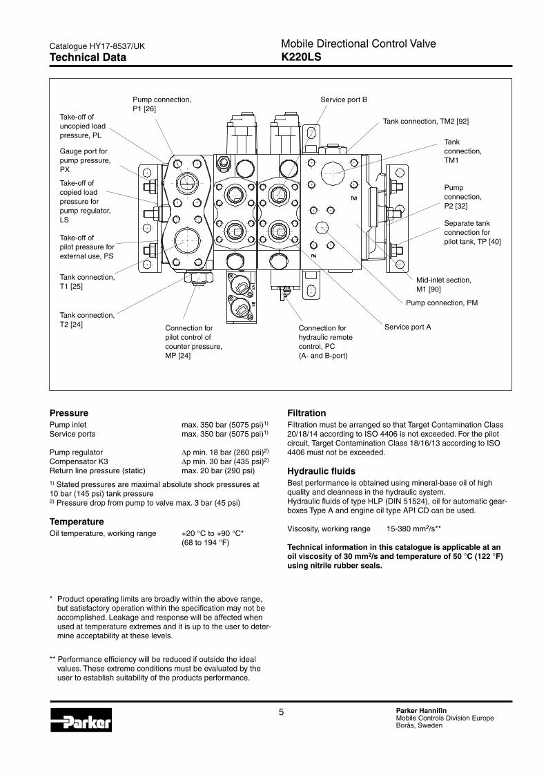
Pump connection, P1 [26]
Take-off of uncopied load pressure, PL
Gauge port for pump pressure, PX
Take-off of copied load pressure for pump regulator, LS
Take-off of pilot pressure for external use, PS
Tank connection, T1 [25]
Tank connection, T2 [24] Connection for
pilot control of counter pressure, MP [24]
Connection for hydraulic remote control, PC (A- and B-port)
Service port A
Pump connection, P2 [32]
Tank connection, TM2 [92]
Service port B
Tank connection, TM1
Separate tank connection for pilot tank, TP [40]
Pump connection, PM
Mid-inlet section, M1 [90]
Technical Data
FiltrationFiltration must be arranged so that Target Contamination Class 20/18/14 according to ISO 4406 is not exceeded. For the pilot circuit, Target Contamination Class 18/16/13 according to ISO 4406 must not be exceeded.
Hydraulic fluidsBest performance is obtained using mineral-base oil of high quality and cleanness in the hydraulic system.Hydraulic fluids of type HLP (DIN 51524), oil for automatic gear-boxes Type A and engine oil type API CD can be used.
Viscosity, working range 15-380 mm2/s**
Technical information in this catalogue is applicable at an oil viscosity of 30 mm2/s and temperature of 50 °C (122 °F) using nitrile rubber seals.
6 Parker HannifinMobile Controls Division EuropeBorås, Sweden
Mobile Directional Control ValveK220LS
Catalogue HY17-8537/UK
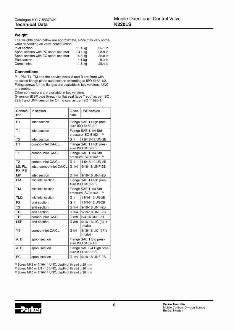
WeightThe weights given below are approximate, since they vary some-what depending on valve configuration.Inlet section 11.4 kg 25.1 lbSpool section with PC spool actuator 13.1 kg 28.9 lbSpool section with EC spool actuator 14.5 kg 32.0 lbEnd section 4.1 kg 9.0 lbCombi-inlet 11.5 kg 25.4 lb
ConnectionsP1, PM, T1, TM and the service ports A and B are fitted with so-called flange plane connections according to ISO 6162-1/2. Fixing screws for the flanges are available in two versions, UNC and metric.Other connections are available in two versions:G-version (BSP pipe thread) for flat seal (type Tredo) as per ISO 228/1 and UNF-version for O-ring seal as per ISO 11926-1.
Connec-tion
In section G-ver-sion.
UNF-version
P1 inlet section Flange SAE 1 High pres-sure ISO 6162-2 1)
T1 inlet section Flange SAE 1 1/4 Std pressure ISO 6162-1 3)
T2 inlet section G 1 1 5/16-12 UN-2BP1 combo-inlet CA/CL Flange SAE 1 High pres-
sure ISO 6162-2 1)
T1 combo-inlet CA/CL Flange SAE 1 1/4 Std pressure ISO 6162-1 3)
T2 combo-inlet CA/CL G 1 1 5/16-12 UN-2BLS, PL, PX, PS
inlet, combo-inlet CA/CL G 1/4 9/16-18 UNF-2B
MP inlet section G 1/4 9/16-18 UNF-2BPM mid-inlet section Flange SAE 1 High pres-
sure ISO 6162-2 1)
TM mid-inlet section Flange SAE 1 1/4 Std pressure ISO 6162-1 1)
TM2 mid-inlet section G 1 1 5/16-12 UN-2B
P2 end section G 1 1 5/16-12 UN-2B
T3 end section G 1/4 9/16-18 UNF-2BTP end section G 1/4 9/16-18 UNF-2BTP combo-inlet CA/CL G 3/8 3/4-16 UNF-2BLSP end section G 3/8 9/16-18 JIC (37°)
(male)YS combo-inlet CA/CL G1/4 9/16-18 JIC (37°)
(male)A, B spool section Flange SAE 1 Std pres-
sure ISO 6162-1 2)
A, B spool section Flange SAE 3/4 High pres-sure ISO 6162-2 2)
PC spool section G 1/4 9/16-18 UNF-2B
1) Screw M12 or 7/16-14 UNC, depth of thread ≥ 25 mm 2) Screw M10 or 3/8 - 16 UNC, depth of thread ≥ 20 mm 3) Screw M10 or 7/16-14 UNC, depth of thread ≥ 20 mm
Technical Data
7 Parker HannifinMobile Controls Division EuropeBorås, Sweden
Mobile Directional Control ValveK220LS
Catalogue HY17-8537/UK
K220-B
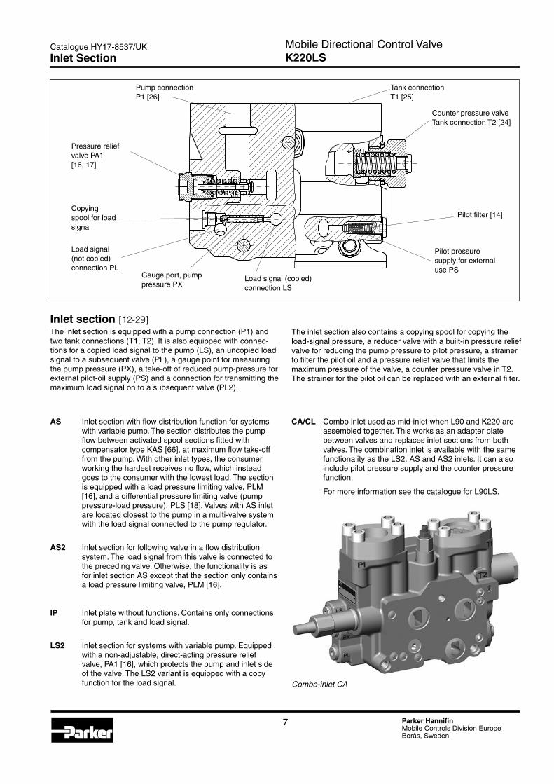
Inlet section [12-29]The inlet section is equipped with a pump connection (P1) and two tank connections (T1, T2). It is also equipped with connec-tions for a copied load signal to the pump (LS), an uncopied load signal to a subsequent valve (PL), a gauge point for measuring the pump pressure (PX), a take-off of reduced pump-pressure for external pilot-oil supply (PS) and a connection for transmitting the maximum load signal on to a subsequent valve (PL2).
The inlet section also contains a copying spool for copying the load-signal pressure, a reducer valve with a built-in pressure relief valve for reducing the pump pressure to pilot pressure, a strainer to filter the pilot oil and a pressure relief valve that limits the maximum pressure of the valve, a counter pressure valve in T2. The strainer for the pilot oil can be replaced with an external filter.
Pump connection P1 [26]
Tank connection T1 [25]
Counter pressure valveTank connection T2 [24]
Copying spool for load signal
Gauge port, pump pressure PX
Load signal (not copied) connection PL
Pilot filter [14]
Pilot pressure supply for external use PS
Load signal (copied) connection LS
Pressure relief valve PA1 [16, 17]
Inlet Section
CA/CL Combo inlet used as mid-inlet when L90 and K220 are assembled together. This works as an adapter plate between valves and replaces inlet sections from both valves. The combination inlet is available with the same functionality as the LS2, AS and AS2 inlets. It can also include pilot pressure supply and the counter pressure function.
For more information see the catalogue for L90LS.
Combo-inlet CA
AS Inlet section with flow distribution function for systems with variable pump. The section distributes the pump flow between activated spool sections fitted with compensator type KAS [66], at maximum flow take-off from the pump. With other inlet types, the consumer working the hardest receives no flow, which instead goes to the consumer with the lowest load. The section is equipped with a load pressure limiting valve, PLM [16], and a differential pressure limiting valve (pump pressure-load pressure), PLS [18]. Valves with AS inlet are located closest to the pump in a multi-valve system with the load signal connected to the pump regulator.
AS2 Inlet section for following valve in a flow distribution system. The load signal from this valve is connected to the preceding valve. Otherwise, the functionality is as for inlet section AS except that the section only contains a load pressure limiting valve, PLM [16].
IP Inlet plate without functions. Contains only connections for pump, tank and load signal.
LS2 Inlet section for systems with variable pump. Equipped with a non-adjustable, direct-acting pressure relief valve, PA1 [16], which protects the pump and inlet side of the valve. The LS2 variant is equipped with a copy function for the load signal.
8 Parker HannifinMobile Controls Division EuropeBorås, Sweden
Mobile Directional Control ValveK220LS
Catalogue HY17-8537/UK
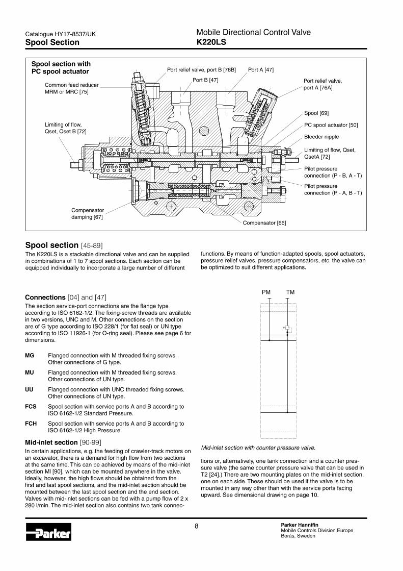
Spool section [45-89]The K220LS is a stackable directional valve and can be supplied in combinations of 1 to 7 spool sections. Each section can be equipped individually to incorporate a large number of different
Spool section with PC spool actuator
Compensator damping [67]
PC spool actuator [50]
Spool [69]
Compensator [66]
Common feed reducer MRM or MRC [75]
Port relief valve, port B [76B]
Port B [47]
Limiting of flow, Qset, Qset B [72]
Port A [47]
Port relief valve, port A [76A]
Bleeder nipple
Limiting of flow, Qset, QsetA [72]
Pilot pressure connection (P - A, B - T)
Pilot pressure connection (P - B, A - T)
K220-3Mid-inlet section with counter pressure valve.
PM TM
functions. By means of function-adapted spools, spool actuators, pressure relief valves, pressure compensators, etc. the valve can be optimized to suit different applications.
Connections [04] and [47]The section service-port connections are the flange type according to ISO 6162-1/2. The fixing-screw threads are available in two versions, UNC and M. Other connections on the section are of G type according to ISO 228/1 (for flat seal) or UN type according to ISO 11926-1 (for O-ring seal). Please see page 6 for dimensions.
MG Flanged connection with M threaded fixing screws. Other connections of G type.
MU Flanged connection with M threaded fixing screws. Other connections of UN type.
UU Flanged connection with UNC threaded fixing screws. Other connections of UN type.
FCS Spool section with service ports A and B according to ISO 6162-1/2 Standard Pressure.
FCH Spool section with service ports A and B according to ISO 6162-1/2 High Pressure.
Mid-inlet section [90-99]In certain applications, e.g. the feeding of crawler-track motors on an excavator, there is a demand for high flow from two sections at the same time. This can be achieved by means of the mid-inlet section Ml [90], which can be mounted anywhere in the valve. Ideally, however, the high flows should be obtained from the first and last spool sections, and the mid-inlet section should be mounted between the last spool section and the end section.Valves with mid-inlet sections can be fed with a pump flow of 2 x 280 l/min. The mid-inlet section also contains two tank connec-
Spool Section
tions or, alternatively, one tank connection and a counter pres-sure valve (the same counter pressure valve that can be used in T2 [24].) There are two mounting plates on the mid-inlet section, one on each side. These should be used if the valve is to be mounted in any way other than with the service ports facing upward. See dimensional drawing on page 10.
9 Parker HannifinMobile Controls Division EuropeBorås, Sweden
Mobile Directional Control ValveK220LS
Catalogue HY17-8537/UK
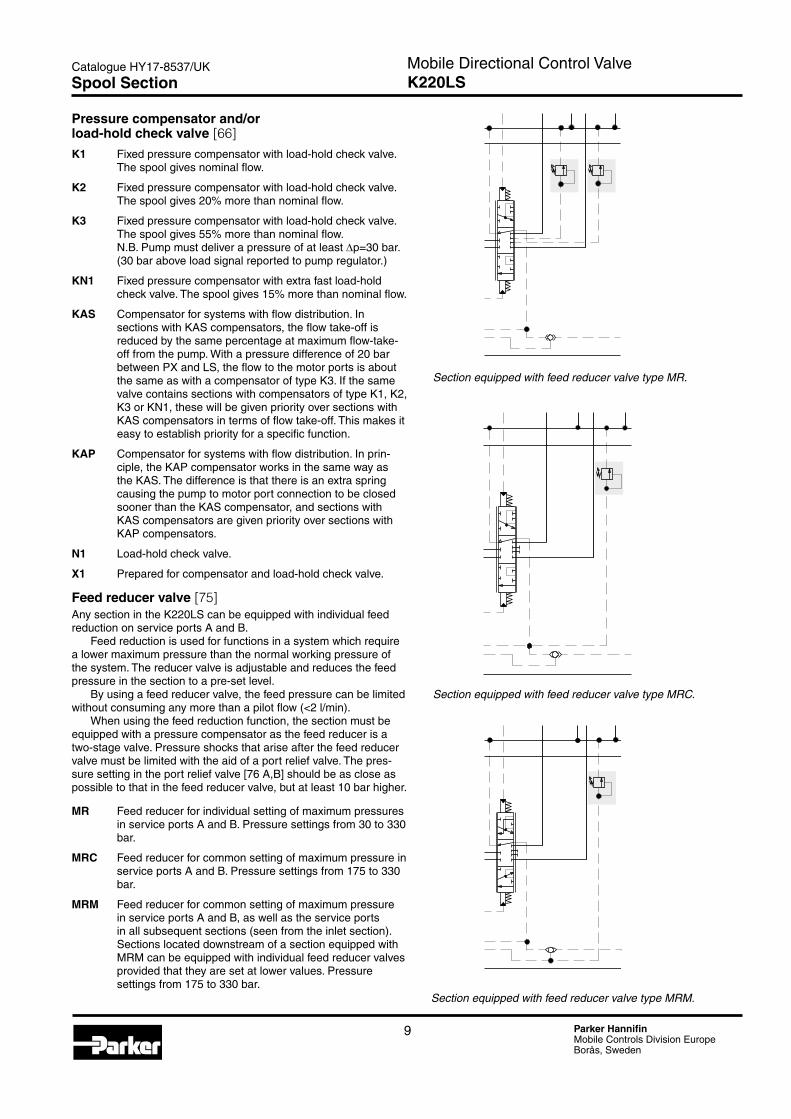
Pressure compensator and/or load-hold check valve [66]K1 Fixed pressure compensator with load-hold check valve.
The spool gives nominal flow.
K2 Fixed pressure compensator with load-hold check valve. The spool gives 20% more than nominal flow.
K3 Fixed pressure compensator with load-hold check valve. The spool gives 55% more than nominal flow. N.B. Pump must deliver a pressure of at least ∆p=30 bar. (30 bar above load signal reported to pump regulator.)
KN1 Fixed pressure compensator with extra fast load-hold check valve. The spool gives 15% more than nominal flow.
KAS Compensator for systems with flow distribution. In sections with KAS compensators, the flow take-off is reduced by the same percentage at maximum flow-take-off from the pump. With a pressure difference of 20 bar between PX and LS, the flow to the motor ports is about the same as with a compensator of type K3. If the same valve contains sections with compensators of type K1, K2, K3 or KN1, these will be given priority over sections with KAS compensators in terms of flow take-off. This makes it easy to establish priority for a specific function.
KAP Compensator for systems with flow distribution. In prin-ciple, the KAP compensator works in the same way as the KAS. The difference is that there is an extra spring causing the pump to motor port connection to be closed sooner than the KAS compensator, and sections with KAS compensators are given priority over sections with KAP compensators.
N1 Load-hold check valve.
X1 Prepared for compensator and load-hold check valve.
Feed reducer valve [75]Any section in the K220LS can be equipped with individual feed reduction on service ports A and B.
Feed reduction is used for functions in a system which require a lower maximum pressure than the normal working pressure of the system. The reducer valve is adjustable and reduces the feed pressure in the section to a pre-set level.
By using a feed reducer valve, the feed pressure can be limited without consuming any more than a pilot flow (<2 l/min).
When using the feed reduction function, the section must be equipped with a pressure compensator as the feed reducer is a two-stage valve. Pressure shocks that arise after the feed reducer valve must be limited with the aid of a port relief valve. The pres-sure setting in the port relief valve [76 A,B] should be as close as possible to that in the feed reducer valve, but at least 10 bar higher.
MR Feed reducer for individual setting of maximum pressures in service ports A and B. Pressure settings from 30 to 330 bar.
MRC Feed reducer for common setting of maximum pressure in service ports A and B. Pressure settings from 175 to 330 bar.
MRM Feed reducer for common setting of maximum pressure in service ports A and B, as well as the service ports in all subsequent sections (seen from the inlet section). Sections located downstream of a section equipped with MRM can be equipped with individual feed reducer valves provided that they are set at lower values. Pressure settings from 175 to 330 bar.
D101875
D101876
D101877
Section equipped with feed reducer valve type MR.
Section equipped with feed reducer valve type MRC.
Section equipped with feed reducer valve type MRM.
Spool Section
10 Parker HannifinMobile Controls Division EuropeBorås, Sweden
Mobile Directional Control ValveK220LS
Catalogue HY17-8537/UK
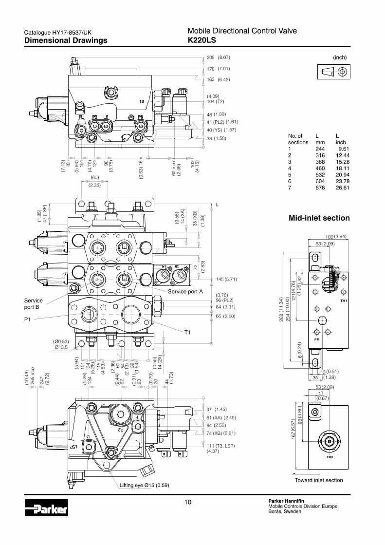
No. of L Lsections mm inch1 244 9.612 316 12.443 388 15.284 460 18.115 532 20.946 604 23.787 676 26.61
max
D101878
L
38
40 (YS)
41 (PL2)
48
104 (T2)
163
178
205
(1.50)
(1.57)
(1.61)
(4.09)
(6.42)
(7.01)
(8.07)
1696121
151
181
60 10
2
(7.1
3)
(5.9
4)
(4.7
6)
(3.7
8)
(0.6
3)
(2.3
6)
(4.1
5)
(60)
(2.36)
47 (L
SP)
(1.8
5)
35 (X
B)
14 (X
A)
(0.5
5)
(1.3
8)72
145
96 (PL2)84
66 (2.60)
(3.31)
(3.78)
(5.71)
(2.8
3)
Ø13,5(Ø0.53)
14 (2
X)
395460115
134
151
44202362134
247
265
max
(10.
43)
(9.7
2)
(5.2
8)
(2.4
4)
(0.9
1)
(0.7
9)
(1.7
3)
(5.9
4)
(5.2
8)
(4.5
3)
(2.3
6)
(2.1
3)
(1.5
4)
(0.5
5)
111 (T3, LSP)
74 (XB)
64
61 (XA)
37 (1.45)
(2.40)
(2.52)
(2.91)
(4.37)
(1.89)
TM1
TM2
PM
53100
3212
125
428
8
6
1335
5317
9816
7
K220-2
(6.5
7)(3
.86)
(2.09)
(0.67)
(0.51)(1.38)
(0.2
4)
(11.
34)
(10.
00)
(4.7
6)(1
.26)
(2.09)
(3.94)
Mid-inlet section
Toward inlet section
Service port B
Service port A
P1
T1
Lifting eye Ø15 (0.59)
(inch)
Dimensional Drawings
E
11 Parker HannifinMobile Controls Division EuropeBorås, Sweden
Mobile Directional Control ValveK220LS
Catalogue HY17-8537/UK

© 2010 Parker Hannifin Corporation. All rights reserved. Catalogue HY17-8537/UK, POD, 11/2010, ZZ
Your local authorized Parker distributor
Parker Worldwide
EMEA Product Information CentreFree phone: 00 800 27 27 5374(from AT, BE, CH, CZ, DE, DK, EE, ES, FI, FR, IE, IL, IS, IT, LU, MT, NL, NO, PL, PT, RU, SE, SK, UK, ZA)
US Product Information CentreToll-free number: 1-800-27 27 537
www.parker.com
Ed
. 201
0-11
-16
Europe, Middle East, AfricaAE – United Arab Emirates, Dubai Tel: +971 4 8127100 [email protected]
AT – Austria, Wiener NeustadtTel: +43 (0)2622 23501-0 [email protected]
AT – Eastern Europe, Wiener Neustadt Tel: +43 (0)2622 23501 900 [email protected]
AZ – Azerbaijan, BakuTel: +994 50 2233 458 [email protected]
BE/LU – Belgium, NivellesTel: +32 (0)67 280 900 [email protected]
BY – Belarus, MinskTel: +375 17 209 9399 [email protected]
CH – Switzerland, EtoyTel: +41 (0)21 821 87 00 [email protected]
CZ – Czech Republic, KlecanyTel: +420 284 083 111 [email protected]
DE – Germany, KaarstTel: +49 (0)2131 4016 0 [email protected]
DK – Denmark, BallerupTel: +45 43 56 04 00 [email protected]
ES – Spain, MadridTel: +34 902 330 001 [email protected]
FI – Finland, VantaaTel: +358 (0)20 753 2500 [email protected]
FR – France, Contamine s/ArveTel: +33 (0)4 50 25 80 25 [email protected]
GR – Greece, AthensTel: +30 210 933 6450 [email protected]
HU – Hungary, BudapestTel: +36 1 220 4155 [email protected]
IE – Ireland, DublinTel: +353 (0)1 466 6370 [email protected]
IT – Italy, Corsico (MI)Tel: +39 02 45 19 21 [email protected]
KZ – Kazakhstan, AlmatyTel: +7 7272 505 800 [email protected]
NL – The Netherlands, OldenzaalTel: +31 (0)541 585 000 [email protected]
NO – Norway, AskerTel: +47 66 75 34 00 [email protected]
PL – Poland, WarsawTel: +48 (0)22 573 24 00 [email protected]
PT – Portugal, Leca da PalmeiraTel: +351 22 999 7360 [email protected]
RO – Romania, BucharestTel: +40 21 252 1382 [email protected]
RU – Russia, MoscowTel: +7 495 645-2156 [email protected]
SE – Sweden, SpångaTel: +46 (0)8 59 79 50 00 [email protected]
SK – Slovakia, Banská BystricaTel: +421 484 162 252 [email protected]
SL – Slovenia, Novo MestoTel: +386 7 337 6650 [email protected]
TR – Turkey, IstanbulTel: +90 216 4997081 [email protected]
UA – Ukraine, KievTel +380 44 494 2731 [email protected]
UK – United Kingdom, WarwickTel: +44 (0)1926 317 878 [email protected]
ZA – South Africa, Kempton ParkTel: +27 (0)11 961 0700 [email protected]
North AmericaCA – Canada, Milton, OntarioTel: +1 905 693 3000
US – USA, Cleveland (industrial) Tel: +1 216 896 3000
US – USA, Elk Grove Village (mobile) Tel: +1 847 258 6200
Asia PacificAU – Australia, Castle HillTel: +61 (0)2-9634 7777
CN – China, ShanghaiTel: +86 21 2899 5000
HK – Hong Kong Tel: +852 2428 8008
IN – India, MumbaiTel: +91 22 6513 7081-85
JP – Japan, FujisawaTel: +81 (0)4 6635 3050
KR – South Korea, SeoulTel: +82 2 559 0400
MY – Malaysia, Shah AlamTel: +60 3 7849 0800
NZ – New Zealand, Mt WellingtonTel: +64 9 574 1744
SG – Singapore Tel: +65 6887 6300
TH – Thailand, BangkokTel: +662 717 8140
TW – Taiwan, TaipeiTel: +886 2 2298 8987
South AmericaAR – Argentina, Buenos AiresTel: +54 3327 44 4129
BR – Brazil, Sao Jose dos Campos Tel: +55 12 4009 3500
CL – Chile, SantiagoTel: +56 2 623 1216
MX – Mexico, ApodacaTel: +52 81 8156 6000
VE – Venezuela, CaracasTel: +58 212 238 5422