Embed Size (px)
Citation preview

Hy-SecurityGate Operators
HYDRAULICSLIDE GATEOperators
With Smart Touch Controller
Installation and Maintenance Manual
Models 222 SS, E, EX, XI333 MS, E, EX222 CF, CE, CX
andDC Battery Operated Models
222 DS, DE, DX
Revision: ___
Hy-Security Gate OperatorsPhone: 1-800-321-9947FAX: (206) 286-0614Internet: www.hy-security.comEmail: [email protected] Date _7/02/01__

Installation and Maintenance Manual
Hy-Security Hydraulic Slide Gate Operatorii
Heavy Duty Industrial Hydraulic Slide Gate Operator
©Copyright 2001 Hy-Security Gate Inc.All rights reserved. No part of this manual may be reproduced by any means:photocopier, electronic or mechanical, without the express written permission of Hy-Security Gate Inc. Additionally, Hy-Security Inc. makes no representations orwarranty with respect to this manual. We also reserve the right to make changes inthe products described without notice and without any obligation to notify anypersons of any such revision or change.

Installation and Maintenance Manual
Hy-Security Hydraulic Slide Gate Operatoriii
Table of Contents
Introduction.....................................................................................................................................vWarranty Registration..................................................................................................................vi
I Safe Gate DesignAvailable Models and Features ..............................................................................................1-2Important Information...................................................................................................................3Entrapment Protection Schematic ............................................................................................4Install an Automatic Operator only When: .............................................................................5Important Instructions for Gate System Owners & Users ..................................................6
II InstallationTools Required – Getting Started with an Automated Gate System............................7-8Installation Preparations and Installation .........................................................................9-12Mechanical & Hydraulic Adjustments ................................................................................... 13
III Smart Touch Set upBasics of Using the Smart Touch Controller....................................................................... 17Installation Configuration for Smart Touch Controller..................................................... 18Wiring Control Inputs to the Smart Touch Controller....................................................... 19Connecting a Master/Slave Pair or an Interlocked Pair.................................................... 21Table of User and Installer Menu Functions...................................................................22-23User Menu: Description Functions Available...................................................................... 24Installer Menu: Description Functions Available ..........................................................25-26Correctional Facility – User Optional Wiring....................................................................... 27Options for User Programmable Output Relays................................................................. 28Setting the Time and Date on the Clock ............................................................................... 29
IV Entrapment ProtectionEntrapment Protection Schematic ......................................................................................... 30UL 325 Standard Requirements for Entrapment Protection Devices ........................... 31Placement and Use of Secondary Pedestrian Entrapment Sensors ............................ 32Installing Gate Edge (Contact Type) Reversing Sensor................................................... 33Installing Photoelectric (Non-Contact) Sensor..............................................................34-35
V Detectors and LoopsDetector Loop Installation Guide.......................................................................................36-38Vehicle Detector Installation & Adjustment Options......................................................... 39Hy-Security Hy-5A Vehicle Detector Installation................................................................ 40

Installation and Maintenance Manual
Hy-Security Hydraulic Slide Gate Operatoriv
Table of Contents, continued
V Detectors and Loops, cont. Standard 11 Pin Vehicle Detector Installation ................................................................... 41 Vehicle Detector Configuration and Anti-Tailgate Modes .............................................. 42 Vehicle Detector & Loop Fault Diagnostics........................................................................ 43
VI Accessories 24 Hr / 7 Day Time Clock Option............................................................................................ 44 Pneumatic Release Option...................................................................................................... 45
VII Troubleshooting and MaintenanceTroubleshooting ...................................................................................................................46-47Maintenance...........................................................................................................................48-49Manual Release Mechanism................................................................................................... 50
VIII Two part Operators (Battery types & 333) Battery DC Systems (DS, DE, DX) Wiring & Control....................................................................................................................... 51 Plan and Elevation for DC Power Supply .......................................................................... 52 Battery Supply diagrams...................................................................................................53-54 Modular Systems (333 MS Series) ..................................................................................55-56
IX AppendixWiring Size Schedules ........................................................................................................57-58Components & Replacement Parts .................................................................................59-63Limited Warranty ....................................................................................................................... 64Index ............................................................................................................................................ 65

Installation and Maintenance Manual
Hy-Security Hydraulic Slide Gate Operatorv
Introduction
Welcome – We would like to take this opportunity to thank you for thispurchase. Hy-Security has manufactured the finest hydraulic gate operators
available since the 1970s. Our commitment to quality and innovation will
become evident as you become familiar with the features and performance ofthis expertly engineered machine. All Hy-Security operators are equipped
with the Smart Touch Controller, a digital electronic brain that offers
unparalleled features.
Please take a few minutes to study the contents of this instruction manual.
The benefits of taking a little extra time to align the gate operator properly andto verify a fully functional installation will ensure customer satisfaction and a
longer life with minimal maintenance costs.
Installers and owners must be certain to thoroughly review and
understand the Important Information regarding pedestrian entrapment
protection contained within this manual. There are hazards associatedwith automatic gates that can be greatly reduced with proper design,
installation use. When an automatic gate is first made functional, the
installer must teach the owners and users how to operate this systemcorrectly. When the installation is complete, leave this manual for the
owner’s use and reference.
Please do not hesitate to give your Hy-Security distributor a call if you
experience any difficulties during the installation. They are experienced and
trained to assist in resolving any problems.

Installation and Maintenance Manual
Hy-Security Hydraulic Slide Gate Operatorvi
For warranty registration, please fill in this information, fax or mail acopy to Hy-Security, then give this manual to the owner of the gate.
Owner Name:_______________________________Telephone number: __________________________
Hy-Security Distributor: _______________________Telephone number: __________________________
Installer name: _____________________________Telephone number: __________________________
Serial number of operator: ____________________Date installed: ______________________________
Model of Operator ___________________________
Warranty RegistrationHy-Security Address: FAX:1200 W Nickerson (206) 286-0614Seattle, WA 98119 Date: ________

Available Models and Features
Hy-Security manufacturers eighteen different models of hydraulic slide gate operators to suit thesize, weight and desired speed of the gate panel. All of the operator models are derived from thestandard 222 SS, upon which this manual is designed. Take a moment to identify the operatormodel you have and note there are some changes in the instructions, especially in regards to finaladjustments. The following chart shows the differences at a glance:
Std. Models 222 SS 222 E 222 EX* 444 XSModular Models 333 MS 333 E 333 EX*Prison Models 222 CF 222 CE 222 CX*24V UPS Models 222 DS 222 DE 222 DX* 444 DX
Features:Horsepower 1HP 1HP 2HP 5HPRate of Travel 1.0 ft/sec 1.0 ft/sec 2.0 ft/sec 1.0 ft/secUL Usage Class 1 – 4 1 – 4 3 – 4 3 – 4Warranty 5 years 5 years 5 years 5 yearsSoft Stop yes yes yes yesBrake Valves no yes yes yesSoft Start no no yes yesDrawbar Pull 300 lbs 300 lbs 300 lbs 1200 lbs*X1 Option (1’/sec) 600 lbs
Weight Capacity 1000 lbs 4000 lbs 4000 lbs contact factory*X1 Option 8000 lbs
Notes: Std. unit brake valve heavier 4 drive wheels2 drive for heavy gates for very heavywheels gates 2 foot/sec gates
Stopping the GateAll models employ a time delay Soft Stop system.Additionally, optional brake valves (shown at right) are usedto control the stopping of heavy or fast moving gates. Thesevalves are exclusive to Hy-Security operators. They areindependently adjustable to allow the gate to stoppredictably and without banging.
Starting the GateWhen starting very heavy gates to accelerate faster thanone foot per second, it is necessary to Soft Start the loadgently, in addition to stopping it smoothly. Soft Start isaccomplished by another Hy-Security exclusive feature wecall an AWOG, which diverts some of the start-up hydraulicflow and thereby allows the gate to accelerate over a periodof about 2 seconds. This is much like letting your foot slowlyoff a car clutch – no lurching when the gate starts. TheAWOG definitely improves the life and performance of agate system and never needs adjustment.
brake valves
AWOG
soft startmanifold

Installation and Maintenance Manual
2
Available Models and Features
Operators for Heavy Gates: E ModelsModels 222 E, 333 E, 222 CE and 222 DE differ from the base model only by the addition of ahydraulic manifold with two adjustable brake valves, shown on the previous page. The brake valvesextends the maximum weight capacity from 1,000 pounds to up to a 4,000-pound gate. Brake valvesare highly recommended for heavy-duty applications.
High Speed Operators: EX Modes (UL class III and IV only)The AWOG soft starting system and the brake valves are keys to safely moving gates faster than onefoot per second. These devices, together with our hydraulic drive, create smooth and predictablehandling for both small lightweight or large heavy gates. The 222 EX, CX, and DX models alsoemploy larger drive wheels and a higher flow rate pump to achieve a speed of 2.0 feet per second.
DC 24-Volt UPS (Un-interruptible Power Supply) OperatorsThese gate operators function from 24 Volts DC Batteries all of the time to achieve a true UPSsystem. Our Un-interruptible Power Supply is the most certain way to know that your gate will workwhen the local AC power fails. This system features fully sealed maintenance free batteries in aseparate insulated and ventilated enclosure. A two-battery version provides at least 3,000 feet ofbackup gate travel. A four-battery version provides at least 8,000 feet of backup travel during localpower loss.
“CF” Correctional Facility OperatorsThe CF models offer an extra heavy 10-gage cover with three different locking options. Type CFoperators are shipped ready to interface to the many options and interlocks commonly used atcorrectional facilities, such as gate position outputs, interlock capability for sally ports and an interfacerelay to control an external solenoid lock.
333 Modular OperatorsThe family of 333 type operators is a two part modular version of the standard 222 operator. Themotor, hydraulic pump and electric controls are located in a separate enclosure from the drive unit.This version allows for a more flexible placement of the operator, which may be required or desirablein some situations involving unique mounting, special security or those wanting a very quiet operator.(When the hydraulic controller is mounted at a distance)
444 Super Powerful OperatorsThe 444 type operators are for heavier gates, weighing up to 50,000 lbs. They employ a much largerchassis with four drive wheels and hydraulic motors, and a five horsepower electric motor to generateup to 1200 pounds of draw bar pull.
The Smart Touch ControllerThis is the brain of Hy-Security’s automatic operators. Truly high technology, but also very rugged toreliably serve in the harshest environments. The Smart Touch Controller can quickly be configured byan installer or user to adapt to about any functional requirement for a specific site. All system settingsare performed with the use of just four programming buttons and an LCD display. The Smart TouchController has no switches of any type to set. An RS232 port for external communication is standard.A real time clock and an EEPROM record system events. With optional software, a log of events canbe downloaded from the RS232 port. Vehicle detector modules will set a new industry standard bycommunicating a host of valuable performance data to the main Smart Touch controller via a serialdata stream, allowing user-friendly diagnostics.

Installation and Maintenance Manual
3
READ THIS FIRST!
Important Information – Review Before Installation
Automatic gate operators provide convenience and security to users. However, because thesemachines can produce high levels of force it is important that all gate operator system designers,installers and end users be aware of the potential hazards associated with improperly designed,installed or maintained systems. Keep in mind that the gate operator is only one component of thetotal gate operating system. It is the joint responsibility of the specifier, designer, purchaser, installerand end user to verify that the total system is appropriately configured for its intended use. Allparties should be informed that entrapment in a moving gate could cause serious injury or death.
CommonIndustrySymbols
Important Instructions for Gate System Designers & Installers:
WARNING: To reduce the risk of serious injury or death, read and follow all instructions inthe gate operator handbook and on the warning labels.
Install an Automatic Gate Operator only When:
q The entry is configured for vehicular use only. Pedestrians must be directed toa separate walk-through entrance. The Warning signs that have beensupplied with this operator must be installed, in manner clearly visible, in thearea of both sides of the gate.
q All openings of a horizontal slide gate are guarded or screened, from thebottom of the gate to a minimum of 4 feet (1.2 m) height above the ground, toprevent a sphere 2 ¼ inches (57 mm) in diameter from passing through anopening anywhere in the gate or the portion of the adjacent fence that iscovered in the open position.
q All exposed pinch points, rollers and wheels are guarded. To reduce the riskof entrapment, the gate must also be installed so that enough clearance isprovided between the gate and adjacent structures both when opening andclosing. Minimize the parallel gap between the gate and the fence.
q The gate has been constructed with physical stops to prevent over-travel inboth directions and has guard posts that prevent the gate from falling in theevent of a roller failure.
-Danger-Keep Away
Attention-Take Note-
EntrapmentZone
PossiblePinch Point

Installation and Maintenance Manual
4
Entrapment Protection DeviceSchematic for Sliding GatesAttention
Guard posts
Keep this gap assmall as possible
Gate edgesensors
Warning signs mustbe on both sides
2 ¼” safety meshprevents reach-through: height notless than 48 inches
Physical travelstop, both ends
Photo Eyes forboth directionseach side of gate
Gate edge sensor,on leading edgeand trailing edge
Note: All wheels must becovered. (Wheels andcovers not shown for clarity)
This schematic view is not meant to recommend the only way to set up your configuration, butto point out the various elements of a proper automatic vehicular gate installation. The gateoperator itself is only one component in the total system. Always install a separatepedestrian walk gate
Audio alarm
Access controlsat least six feetaway from gateand operator
Stop and resetbutton
Physical travelstop, both ends
Photo Eyes forboth directions

Installation and Maintenance Manual
5
Install An Automatic Gate Operator Only When:
q The gate moves freely in both directions. Never over-tighten a clutch or pressure reliefvalve to compensate for a stiff gate.
q The operator will be installed on the secured (non-public) side of the gate.
q The operator will be properly electrically grounded and the intended supply voltagematches the voltage label on the operator.
q The controls that operate the gate have been mounted far enough from the movinggate such that users cannot touch the gate while operating the controls. All easilyaccessible controls must have a security feature to prevent unauthorized use.
q The operator controls will be located in a clear line-of-sight to the gate. Radio controlsand other remote access controls must be connected only to the Remote Open input,which cannot perform a reset function.
q The required external entrapment sensors will be installed. Be certain to carefullyreview the instructions for placement, installation and adjustment of these externalentrapment sensors. External entrapment sensors must function to reverse themovement of the gate in both the opening and closing directions. If edge (contact)sensors are used, they are to be mounted on the leading edge, trailing edge of thegate, as well as post mounted on the inside and outside of the gate (See figure on pg.4). If photo eyes or other non-contact sensors are used, they are to be mounted inlocations most likely to guard against entrapment. A combination of contact and non-contact sensors may be used, but all must be recognized components under the UL325 standard. See pages 32 and 33 for details on the requirements.
q The automatic operator is labeled as appropriate for both the type and UL usage classof the gate. Note: Sliding gate operators installed in Class I & II applications must notmove the gate faster than one foot per second.Class I: Intended to serve single to four family residential uses*Class II: Multi-family use, or any application intended to serve the general public*Class III: Commercial applications not intended to serve the general public*Class IV: Highest security. Security personnel prevent unauthorized access*
q Sliding gate operators installed in Class III & IV applications do not have a speedrestriction and the secondary entrapment sensor requirement is met if the system isconfigured as described for Class I & II use, or by the following alternate means:Employ the use of a 100dB buzzer, which sounds at least 3 seconds before the gatemoves, and/or functions only by use of a constant hold type push button control

Installation and Maintenance Manual
6
Important Information For Gate System Owners & Users
WARNING: To reduce the risk of serious injury or death, read and follow all instructions inthe gate operator handbook and on the warning labels.
Save These Important Owner and User Instructions:(Installers – be certain to instruct the owners and users about the following items)
q Automatic gates are for vehicular use only! Provide walkways and signs to directpedestrians to a separate walk-through entrance. Because an automatic gate canstart at any time without warning, always keep people away from the area of the gate.The Warning signs that have been supplied with this operator must remain installed,in manner clearly visible, in the area of both sides of the gate.
q Never allow children to use or play with controls that operate the gate. Keep allremote controls, especially radio transmitters, away from children.
q Teach all users how to turn off the electric power and how to release and move thegate manually. Use the manual release only when the gate is not moving.
q Test the function of the gate operator monthly. The gate MUST reverse its directionof travel upon contact with a rigid object, and/or stop upon a sensing a 2nd sequentialactivation prior to reaching a full travel limit. Also test for the normal function of anynon-contact sensors. If the gate system employs the use of a transmitting edgesensor, be especially certain to test and replace its battery on a routine basis.
q KEEP AUTOMATIC GATES PROPERLY MAINTAINED. Have a professional gateinstaller perform routine tests of the entrapment protection sensors, such as photoeyes and gate edges. Also, make all necessary repairs to the gate hardware to keepthe gate running smoothly. Failure to adjust and test a gate operator properly canincrease the risk of injury or death.
q In addition to appropriately placed external entrapment sensors, ask your installer toreduce the setting of the pressure relief valve to the lowest setting allowable thatreliably operates the gate. This valve controls the force of the operator, and thesensitivity of the inherent reversing sensor.
q Do not attempt disable or muffle the Warn Before Operate buzzer, except inclass IV restricted access locations. This buzzer provides an alert that the gateis about to move.

Installation and Maintenance Manual
7
Tools Required for an Efficient Installation
5. Hammer
6. Screwdriver sets,Straight and Phillips
7. Wrench set, open end,1/4" through 1"
8. Electric drill and bits,1/8" through 3/8"
9. Roto-hammer and bits,3/8" & 1/2"
10. Level—it doesn’t need to looklike this one, but the installationneeds to be level!
11. Two pair wide jaw vicegrip pliers, or two C clamps,4" capacity
4. Allen wrench set3. Concrete anchorbolts, four 1/2" x 4"
2. Carpenterspencil or crayon
1. Chalkline or otherbuilders string

Installation and Maintenance Manual
8
Getting Started with an Automated Gate System
• How our hydraulic operator worksHy-Security industrial slide gate operators rotatepolyurethane treaded drive wheels which grip a rigidmetal drive rail and feed it right or left during the gatetravel. The drive wheels are clamped above andbelow the drive rail and are directly coupled topowerful hydraulic motors, which can easily movehuge gates. This simple yet durable drive system isone of the unique features giving our hydraulicoperators their reputation for reliability.
• Accessory CompatibilityHy-Security’s Hydraulic Slide Operators are fully compatible with all standard access control devicesand entrapment protection devices, some of which are listed below.
• Pedestrian Entrapment ProtectionRead and understand all the Important Information in Section 1, the Entrapment ProtectionSchematic on pg. 4 and the UL requirements on page 3 before beginning the installation. Beabsolutely certain that the required type and quantity of Entrapment Protection devices have beensupplied and that you understand how to install them correctly. Contact your local distributor withquestions about Entrapment Protection.
Advanced Access ControlAccess Control Interface
Card ReaderKeypad
Telephone EntryInput/Output
Computer InterfaceRS232/485
Obstruction Sensing DevicesInherent Sensing Device
Gate EdgesPhoto Eyes
Vehicle Detectors
SecurityKey Locks
Closed CircuitTelevision
Gate Position IndicatorInterlock/Sally Port
Gate Status Indicator
InformationSignsLabels
Warnings
Basic Access ControlRadio Transmitter
Long Distance ControlPushbutton Control StationProgrammable Time Clock
Card Reader

Installation and Maintenance Manual
9
Installation Preparation Checklist
1. Read all of the instructions, especially theImportant Information in Section 1 at thebeginning of this manual, before you attemptinstallation. This section is focused uponmechanical installation. For electrical setup,refer to Section 3, on system configurationand use of the Smart Touch Controller.
2. Check to see that the mounting slab is therecommended size and ready to have anoperator attached. Also check thatelectrical conduits are correctly located toenter the chassis. Hy-Security recommendsa slab reaches below the local frost line andextends somewhat above grade. See thefootprint plan and elevation view on page14 & 15.
3. Make sure the gate rolls smoothly in both directions, without any binding of the gate hardware. Ifthe gate is warped or hard to move, stop and fix the gate before attempting to automate.
4. Verify that you have covers for all exposed gate supportwheels. These must be installed. Also, look around toidentify all of the potential pinch points and hazardous areas,and plan the best location for the entrapment protectiondevices and warning signs. Remember that you are requiredto advise the owner regarding the potential hazards of anautomatic gate and about the function of the entrapmentprotection sensors that you have selected and installed.
5. There are 3 steps to a perfect install: location, location, location. One of the most criticaladjustments in installation will be to make sure the operator is located the proper distance from thegate, and that the gate and operator are as parallel as possible. See Figure C below. Preparesome shims for aligning the drive rail.
Driver raillocation:
Gate distancefrom operator:
Figure A
Remember tocover all four ofthe cantilevergate wheels
Figure B
fence
drive rail 1 ¾ “1 ¾” slab
operator
Figure C

Installation and Maintenance Manual
10
Installation
1. Drill four holes for concrete anchorsEach operator comes with a paper template with the anchor slots.Place the template on the slab; making sure that it is parallel to and1 3/4" from the gate. Trace the slots, remove the template, and thenscribe the locations for your anchor bolts. Drill holes for the anchorbolts in the center of the slots you marked, so that you will havesome room for adjustment. There are six mounting slots in thechassis, install at least four ½ " x 4" concrete anchor bolts, usingtwo per side.
2. Line up the operatorPut the operator in position onto the anchor bolts. Verify thatthe operator is parallel and 1 3/4" away from the gate onboth the left and right sides, and then tighten the anchorssecurely.
3. Two part Operators (battery models and 333 modularmodels)These two part operators come with a separate enclosure,which should be mounted within 10 feet of the operator, butnot more than 100 feet. We recommend wall mounting orusing two 4” posts, with horizontal mounting strut to create asupport for this enclosure.
4. Bolt the Drive Rail to the Gate PanelConnect multiple sections of drive rail together with ¼” roll pins for a perfect splice. The drive railmust be bolted to each vertical member of the gate panel. This may be done with U-bolt clamps orthrough bolts, however U-bolt clamps allow for easy up down adjustment. If the gate is bent orwarped, shim the drive rail so that it is straight + ¼” throughout the travel of the gate. When the driverail has been installed at the correct height, the top surface is 9 ¾” above the operator base. A labelon each side of the operator indicates the correct height.
5. Install Limit Ramps on Underside of Drive RailPush the gate to the fully closed position and drill a 3/8”holein through the drive rail to mount a 12” plastic limit rampunder the drive rail, in the wheel channel, at a location thatwill trip the limit switch approx. 6” before the exact spot youwant the gate to stop. Adjust the lever arms on the limitswitch so that the roller clears the underside of the drive railby at least 1/4 inch. Push the gate fully open and repeat thisprocedure with the other limit ramp. See the Drive Raildrawing S22 on pg. 16.
slab
fencepost Shim asnecessary
Drive rail
Drive rail
Limit Roller
Limit switchLimit ramp
Roll pinsline updrive railsegmentsto assureperfectsplicing

Installation and Maintenance Manual
11
6. Install Grip Tape to Underside of Drive RailTwo pieces of grip tape have been provided that should be installed on the underside of the driverail. Place the tape on the first and last 2 ft. of travel, just in front of each limit ramp. Be certain thedrive rail is clean and dry, and then peel off just a bit of the backing to expose only about 2” of theadhesive. Attach the tape to the underside of the drive rail, within 1” of the front of the limit ramp.Now that the tape is lined up, peel the remainder of the backing away and attach the full length ofthe tape. Repeat this procedure for the other end of the drive rail.
7. Clamp the Drive Wheels to the Drive RailWhen the wheels are fully clamped on the drive rail, thered spring should be compressed to 2” in height. Ifadjustment is necessary, turn the nut at the bottom ofthe threaded rod assembly. Slightly less compression isokay for lighter gates. See Use of Manual Release onpg. 48
8. Electrical Power ConnectionThis operator is intended for permanent installation, soall electrical conduits must be properly connected to thecontrol box. The entry for the primary power is a ½ - ¾”knockout on the left side of our control box next to theon-off switch. When this operator was manufactured, itwas built to run on a specific voltage and phase for linepower. Make sure you have compared the line voltageand phase available with the nameplate on this machine.They must match! Be certain that the wire size of thebranch circuit that will supply the operator vs. thedistance of the run from the main panel is large enoughto avoid excess voltage drop. Also be sure the operatoris electrically well grounded. See the Appendix, pg. 58-59 for correct wire sizes and detailed electrical wiringinformation.
9. Primary Tap of Control Transformer(not on battery operators)Check to make sure that the primary tap on the controltransformer matches the line voltage you haveconnected to the operator. Measure the line voltagecarefully to distinguish between 208V and 230V branchcircuits. A label on top of the transformer identifies thevarious voltage taps.
10. Electrical Power for Two Part 333 type OperatorsThe primary AC power must be routed to the controllerenclosure with the pump, but there must also beconduits between the gate operator and the controllerenclosure.Note: AC power is not needed in the gate operator, unless there is an optional heater. Aminimum of two separate conduits must be provided, 2” for the hydraulic hoses and ¾” for theelectrical interconnections. Unless there are accessories in the gate operator, the onlyelectrical interconnection between the two enclosures will be three wires between the twoterminal strips for the limit switches. Join the hydraulic hoses by plugging the quick couplingtogether according to the hand of the gate. See the drawing in Section 7, pg. 57.
manual release
Verify 2”whenengaged
Figure
On/off switch
Stop/reset
PowerConnection
Control transformerprimary taps
Figure

Installation and Maintenance Manual
12
11. Connections for Two Part Battery OperatorsThe primary AC power must be routed to the DC power supply enclosure, but there must also be atleast one 1½ ” conduit between the gate operator and the DC supply enclosure. Note: AC power isnot needed in the gate operator enclosure, unless there is an optional heater. Three separate DCcircuits are required between the battery supply and the gate operator. Heavy gage wires to supplythe motor and two 14-gage circuits for the controls. The heavy gage wire must be at least 6-gage ifthe DC supply is within 20 feet of the operator, but must be increased to 2-gage if the DC supply islocated farther from the operator, or the this is an EX - 2’/sec model. Also see page 49 titled “Wiringand Control Configuration for DC Operators" and Drawing E125 in Section 7, pg. 51.
12. Check the “Hand” of the OperatorAll slide operators must have their “hand” setbefore they can function. The “handing” mustbe set both by the proper hydraulic hoseconnection and electrically. The hoseconnection for proper handing is described on alabel near the hose connection point. Also, seethe instructions to set handing on page 18“Installation Configuration for Smart TouchController.” Handing is viewed by standing in themiddle of the road on the inside looking out.
13. Replace the Blue Plug!Replace the blue plastic shipping plug on the front side of the pump with the black breather cap.
14. Setup Smart Touch ControllerThe operator controls will not allow the gate to function until the Smart Touch Controller has beenconfigured. Wait to connect the external controls until you have reviewed the Smart TouchController instructions and tested the basic functions.
Note: Hy-Security has an installation CD available free of charge to installers. Call a Hy-Securitydistributor for a copy.
Remove the blueplastic shipping plug
and replace withblack breather cap
To change handconnect hoses
according to labelon tank

Installation and Maintenance Manual
13
Mechanical and Hydraulic Adjustments
1. Drive Wheel Spring TensionWhen the drive wheels are fully clamped on the rail, the red spring should be compressed to 2” inheight. If adjustment is necessary, turn the nut at the bottom of the threaded rod assembly. Slightlyless compression is okay for lighter gates. (See Figure on pg. 11)
2. Drive RailVerify that the drive rail does not vary more than 1” up and down, or ¼” in and out throughout theentire horizontal travel of the gate. Re-alignment is simple if the rail is mounted with U bolts. Toadjust in and out, loosen the U bolts and add or remove shim stock. To adjust up or down, loosenthe U bolts and simply tap the rail with a hammer until the correct height is reached. Adjusting therail in or out requires inserting shims between the rail and the gate where necessary.
3. Brake Valves (suffix E, EX models only)If your operator is equipped with brake valves, their properadjustment is important for smooth operation of the gate. Inorder for the brake valves to have time to function, the limitramp must trigger the limit switch at least six inches beforethe point at when you want the gate to stop. Adjustment ofthe brake valves, one for each direction of travel, willdetermine how quickly the gate actually stops. If adjustmentis needed, loosen the 9/16” lock nut on the top of the brakevalve and turn the adjustment stem, in about ¼ turnincrements, with an Allen wrench. The adjustment worksopposite of typical, such that a counter-clockwise adjustmentwill stop the gate more rapidly. If the adjustment is set tooloose, the limit ramps will bang into the drive wheels. If theadjustment is set too tight, the system pressure will increase,the gate speed may decrease and the gate will jerk to a stop.Set the brake valve to achieve a controlled smooth stop, andthen retighten the locking nut to hold the setting.
4. Pressure Relief ValveThis valve, which governs the maximum system hydraulic pressure available, is located on thebackside of the pump, just above the limit switch. Installers are encouraged to reduce the reliefvalve setting to the lowest pressure that will reliably operate the gate. A lower setting reduces themaximum force that the gate operator can exert, saves energy and reduces system ware. Ifadjustment is needed, loosen the 9/16” lock nut and turn the adjustment stem with a wrench. Lowerpressure (force) is achieved by turning the adjuster stem counter-clockwise. The only way to displaythe actual relief valve setting is to unplug the hydraulic hoses from the quick disconnect fittings. Becertain to retighten the locking nut to hold the desired setting and reconnect the hoses correctly.Also see the drawing in Section 6, pg. 46 for the location and a schedule of factory pressure reliefsettings.
5. Directional and Quick Stop ValvesThese two valves are solenoid operated. The directional valve is below the motor near the front ofthe pump and energizes in order to direct the hydraulic flow to open the gate. The quick stop valve,which is near the back of the pump energizes at the beginning of a cycle to allow no load motorstarts and at the end of each cycle to aid in decelerating the gate. No adjustment of these valves ispossible or ever needed.
Optional brake valves CCW = quicker stopLeft valve controls openRight valve controls close

Installation and Maintenance Manual
14

Installation and Maintenance Manual
15

Installation and Maintenance Manual
16

Installation and Maintenance Manual
17
Basics of Using the Smart Touch Controller System
Read this page if you are unfamiliar with using the Smart Touch Controller.
You must learn to navigate and change menu settings within the Smart Touch Controller before aninstallation can be completed or any control settings or function changes can be made.
Until a new operator has been configured, the controls are not functional and the display islocked in the menu mode until the User Class 1-4, and Left or Right hand use have beenselected. See the next page for instructions on how makethese settings.
1. There are five buttons on the membrane switch pad thatprovide control of everything. The Open, Close andStop buttons serve as a three-button control station, butin the Menu Mode, they become Previous, Next andSelect buttons. The Program Menu button is used toboth enter and exit the Menu Mode. The Reset buttonclears all Errors and Faults that may occur and returnsthe control to its normal functioning state.
2. When in a Menu Mode, changes to be made to a Menusetting are accomplished by pressing the Previous, Nextand Select buttons in the following sequence:
a. Press the Next button to move forward throughthe list of menu items that are available, asshown on pages 22 and 23, or press thePrevious button to move back to an item that yourecently passed.
b. Press the Select button if you wish to make a setting change to a menu item. Themenu item will flash to indicate that its setting is ready to be changed.
c. Press Next to move forward or Previous to go back to an earlier setting choice.
d. When you have located the setting that you want to use, press the Select button andthe program will accept the change and stop blinking.
e. The Program Menu button does not allow an exit to Run Mode while a selection is stillblinking. Press the Select button to stop the blinking, then you may exit to Run Mode.
f. Pressing the Next or Previous buttons when the menu item is not blinking will move tothe next or previous menu item.
g. When done, press Program Menu to exit to the Run Mode.
3. Once configured, the operator will be in the Run Mode. From the Run Mode, to gain accessthe User Menu or the Installer Menu, follow these steps:
a. Note that the Program Menu button will not function unless the gate is at rest and noopen or close inputs are active. Verify system status by pressing the LED button todisclose any active inputs. There also must not be any Alerts, Faults or Errors. Pressthe Reset button to clear the system if necessary.

Installation and Maintenance Manual
18
b. Press the Program Menu button and watch the LCD scroll the system data, or pressthe Program Menu key a 2nd time to skip the scroll. The scrolled data displays theinformation in the table on page 22.
c. The LCD display scroll will stop at the menu item for the automatic close timer setting[Ct __]. This is the first item in the User Menu.
d. To access the more detailed Installer Menu, the system must first be in the UserMenu, and then simultaneously press the Reset button and the Open button. TheLCD will change to display the UL usage class menu item [uC __] This is the first itemin the Installer Menu.
4. Pressing the Program Menu button when the User or Installer Menu is not blinking will returnthe system to the Run Mode.
Installation Configuration for Smart Touch Controller
Setting Operator Handing and Usage Class
1. Connect the hydraulic hoses to the quick couplers on the pump in order to configure left orright hand opening function (as viewed from the secured side of the gate). There is a labelnear the connection point describing this procedure. Also see the illustration on page 12. Ifthe hoses are connected incorrectly, the gate will run backwards (close when open button isactivated) and this may trigger an error [Err 1] on the LCD display. (The Reset button mustbe pushed if this happens).
2. Turn on the power switch and observe that the LCD will first show the software version, andthen stop at a steady display within two seconds. If the display reads [uC 0] go to step 3. Ifthe operator has previously been configured, the Installer Menu must be accessed in order toreach the system configuration menu items: see step 3d at the top of this page.
3. When turning on the power for a new machine, the LCD display directly enters the InstallerMenu at the [uC __] menu item, which is for selecting the user class as defined by UL.Select [uC 1] - [uC 2] - [uC 3] or [uC 4] depending upon the use application. See Section 4,pg. 31 for UL usage class definitions.
4. To set the operator handing, use the “Next” button and move one click down the menu toitem [Sh __] Enter r for right hand or L for a gate that opens to the left. Never alter the limitswitch mounting or change the order of their connection to the controller board. At this pointyou should exit the Installer Menu, by pressing the Program Menu button. The LCD displayjumps to the close timer [Ct__] setting in the User menu, which may now be set. Either pressthe Program Menu button again to exit to normal run mode or set the close timer by thesame programming sequence described at the previous page.
5. Note that the Installer menu cannot be exited by any means until the selection for ULusage class [uC __] and the selection for gate handing [Sh __] have been entered.
6. Test for normal function of the gate operator, with the wheels unclamped, by running it bothopen and closed from the pushbuttons on the membrane switch pad. Neither limit switchshould be triggered at the start of this test or an alert [ALE6] may trigger because the controldid not sense gate motion. If this occurs a new input will restart the motor.

Installation and Maintenance Manual
19
Wiring Control Inputs to the Smart Touch Controller
1. Test the basic open and close operator function before wiring the external control inputs.This makes it easier to troubleshoot if an unexpected function issue arises.
2. Each input has an LED to indicate when that input is active. To disclose the input status, theLED tact button must be pushed. This button is in corner near the Stop input.
3. All of the control device inputs listed below are shown as a single terminal input because theother wire is connected the Common Terminal Buss on the Power Supply board. TheEmergency Close and Fire Dept. Open inputs are an exception and require a +24 Volt input inorder to be activated. The +24 is available at the spade terminals next to the Common Buss.
Smart Touch Controller Inputs1) *Stop Push button (N.C. input, jumper to Common if unused)
2) *Open Push button (not for radio or remote access controls)
3) *Close Push button (not for radio or remote access controls)4) Remote Open & Radio Control (For radio / remote open device
- menu opt. to also close)5) Open/Close button (pushbutton or radio controls)6) Partial Open (installer adjustable from 7-99 seconds)7) Open interlock input or Time clock Open (menu configurable
for one or the other function)8) Free Exit vehicle detector9) Disable Free Exit vehicle detector10) Inside Obstruction vehicle detector (Inside reversing loop)11) Outside Obstruction vehicle detector (Outside reversing loop)12) Shadow/Reset vehicle detector (Shadow is for Swing gates,
Reset is for Arm gates)13) Edge Sensor (one input works for both directions of travel)14) Photo eye Common Power (both to supply PE power Com &
PE output Com)15) Photo eye Open direction16) Photo eye Close direction17) Charger AC power loss (only used in battery type operators)18) Spare Input (unused – may have function in custom
applications)19) *Emergency Close (must menu enable and input +24 Volts to
trigger) Overrides photo eyes, gate edge & vehicle detectors.20) *Fire Dept. Open (must menu enable and input +24 Volts to
trigger) Overrides photo eyes & gate edge.
* Do not connect an external control input toterminals #1, 2 or 3, unless the controls arelocated such that there is a clear view of theentire gate area. For controls not within sight,use input terminals #4, 5, 6 or 7.
* The Emergency Close and Fire Dept. Open inputs are to be usedonly if access to these controls are guarded in sufficient mannersuch that there is always supervision when activated.
Attention

Installation and Maintenance Manual
20

Installation and Maintenance Manual
21
Connecting a Master / Slave Pair
Configuring two operators to be a Master & Slave pair is easy with the Smart Touch Controller.There is no need to order a special model or any adapters. The area of the board marked DualGate employs a 3-wire RS485 serial port for communication between Master & Slave operators.
1. An electrical conduit for the interconnecting wires must span between the two operators.
2. Complete the installation of both of the operators as separate machines and verify that theirbasic functions are correct as solo operators before interconnecting them.
3. The two gate operators should be supplied by home runs from separate 20 Ampere circuitbreakers in the main panel, but if there is only one circuit, be absolutely certain that thebreaker and wire size is sufficient for the load of two motors. See the Appendix.
4. External control inputs, vehicle detectors and entrapment protection sensors may beconnected to either gate operator without regard to preference.
5. To interconnect the two operators, route a shielded twisted pair with an internal ground wirebetween the electric control boxes and connect to the RS485 Dual Gate terminals, inmatching order on both machines: In the RS485 shaded area connect the terminals forMaster Com to Slave Com with the ground shield trace wire, and connect the Master A toSlave A and the Master B to Slave B using the insulated twisted pair of wires.
6. The Installer Menu in each machine must be set as a Master or a Slave under menu item[dg__]. Set one operator as a Slave [dg_1] and the other as a Master [dg_2]. If the functionof any external input is to be different than the factory default, configure for the desiredfunction on the operator where that input is connected. Internal functions, such as the closetimer or reversal distance, are controlled by the Master operator regardless of the settings inthe Slave.
7. Once set as a Master or a Slave the operators will be in constant communication with eachother. If that communication stops because the wires become severed or one operator isturned off, both machines will cease functioning and the LCD will display Err4, which is aMaster/Slave communication error. This error cannot be reset until both machines arefunctional and communicating properly again.

Installation and Maintenance Manual
22
Smart Touch Controller User Menu Functions
Initial Power Up – When power is turned on, the display will disclose the software revision:Display Revision Number 2s delay Displays software version Number, ex. [h2.01]
System Data and accessing the User Menu Settings:If the gate is stopped in the Run Mode, pressing of the Menu button accesses the User Menu.After the menu button is pressed, the LCD will scroll the system data in the table below. Thescrolling display stops at the close timer setting, which is the beginning of the User Menu. To exitthe Menu Mode, the display must not be blinking, then simply pressing the Menu button will returnthe display to the Run Mode and re-enable the controls. The menu mode will also automaticallyreturn to the Run Mode if there is no activity for two minutes.
Data Displayed in Scroll Time DescriptionS1 [SLAu] or [LEAd] 2s SLAVE Operator or LEAd Operator (master)S2 [ot 1] Gate type (1-5) 2s Operator type: 1 =HSG, 2 =HRG, 3 HVG, 4 =HTGS3 [_rh_] or [_Lh_] Hand setting 2s Displays hand configuration [_rh_] or [_Lh_]S4 [uC _] UL usage class (1-4) 2s Installer setting of usage class: type 1-4S5 [d___] 24VDC Buss Voltage 2s Actual VDC buss voltageS6 [CC__] Life cycle counter 2s High digits of 6 digit life cycle counterS7 [____] Life cycle counter 2s Last 4 digits of 6 digit life cycle counter
Read through the options available in the User Menu and the Installer Menu on the next page andyou can see that the functions of this gate operator can be configured to suit most any specific need.Once you have learned to navigate the menus, as described in #3 on page 11, and how to change asetting, as described in #5 on page 12, the full range of features and choices of the Smart TouchController are available to use. The User Menu contains the basic configuration items and theInstaller Menu contains the more advanced menu items.
User Menu Options Default DescriptionU1 [Ct 0] Close timer setting 0 0 = timer off or 1 – 99 secondsU2 [hC 0] Momentary Close 0 1= Constant hold Close PB required to close gateU3 [ho 0] Momentary Open 0 1= Constant hold Open PB required to open gateU4 [AP 0] Power loss function 0 0 – 3 (0=Type A, 1 = B, 2 = C, 3 = D) See page 49U5 [ro 0] Radio control option 0 0 = Open only, 1 = Close only when full openU6 [bF 2] Warn before operate 2 0 = none, 1 = 3 seconds before and enables Warn
while operate, 2 = warns before + 2 seconds duringU7 [FA 0] Forced open Alert and
automatic gate reposition0 0 = disabled, 1 sound buzzer (2 pulses/sec) if forced
open for more than four seconds, time out in 30 SecU8 [dA 0] Drift Closed Alert and
automatic gate reposition0 0 = disabled, 1 sound buzzer (2 pulses/sec) if drift
closed and cannot reopen within four seconds.U9 [PE 0] Photo Eye Align Mode 0 0= off, 1 = on (auto off when close limit triggered)U10 [CL 0] Clock set (24 hour type) 0 0= display, 1= minutes, 2= hours, 3= day, 4= monthU11 [Ld 5] LCD Contrast set 5 1 - 9 = Adjusts contrast of the display
These Notes Refer to the Menu Above:S1 Appears only if the operator is configured as a master or a slave unitU1 Close timer setting does not appear when set for constant contact close functionU4 Power loss function only appears if factory has provided DC battery type operatorU6 We strongly advise never disabling the Warn Before Operate buzzer.

Installation and Maintenance Manual
23
Smart Touch Controller Installer Menu Functions
The Installer Menu can be accessed only by entering the User Menu first, and then by pressing theReset button and the Open button simultaneously.
To restore the factory default settings, go to menu item [Fd_0] and change the setting to 1,then press the Program Menu button. The entire menu will reset to the factory defaults.
Installer Menu Options Default DescriptionI1 [uC 0] Set UL Usage Class 0 0 = gate disabled, Set Class 1 through 4 useI2 [Sh 0] Set Handing of gate 0 0 = gate disabled, r= Right Hand, L = Left HandI3 [Fd 0] Load Factory Defaults 0 0 = disabled, 1 = Load defaults (resets entire menu)I4 [dg 0] Set Master/Slave type 0 0 = solo operator, 1 = Slave unit, 2 = Master unitI5 [Ch 0] Set AC Charger or Solar 0 0 = DC + AC charger 1 = DC + Solar chargerI6 [Fo 0] Enable Fire Dept. Open 0 0 = disabled, 1 = enabledI7 [oC 0] Enable Emergency close 0 0 = disabled, 1 = enabledI8 [SE 3] Inherent Sensor sens. 3 1 – 9 sensitivity (9= least sensitive)I9 [SS 0] Inherent Sensor function 0 1 = stop only (note, functions in usage class 4 only)I10 [LC 0] Leaf delay Close 0 0 = none (1-7) ½ second stepsI11 [Lo 0] Leaf delay Open 0 0 = none (1-7) ½ second stepsI12 [rt 0] Maximum run timer 0 0 – 1 (0= 60 Seconds, 1 = 300 Seconds)I13 [Po 0] Partial Open distance 0 0 = none, or 7 – 99 secondsI14 [EC 0] PEC reverse to open 0 0 = stop only, 1= 2 sec reverse to openI15 [EO 0] PEO reverse to close 0 0 = stop only, 1= 2 sec reverse to closeI16 [gr 0] Edge reverse to open 0 0 = reverse fully open, 1= 2 sec reversal onlyI17 [Sr 1] IES reverse to open 1 0 = reverse fully open, 1= 2 sec reversal onlyI18 [PC 0] Set PEO/ PEC – NO/NC 0 0 = Normally Open, 1 = Normally ClosedI19 [gC 0] Set Edge input – NO/NC 0 0 = Normally Open, 1 = Normally ClosedI20 [tC 1] Time clock/ Interlock input 1 0 = select Time Clock, 1 = select Open InterlockI21 [or 1] OOLD detector function 1 0 = pause only, 1 = enable reversing to openI22 [ir 1] IOLD detector function 1 0 = pause only, 1 = enable reversing to openI23 [dL 1] Vehicle detector logic 1 1-4, 1 = std, 2 & 3 = quick close, 4 = full anti-tailgate*I24 [r1 0] User relay 1 option 1 0 = disabled, 1 – 19 = see output options page 22I25 [r2 0] User relay 2 option 6 0 = disabled, 1 – 19 = see output options page 22I26 [r3 0] User relay 3 option 1 0 = disabled, 1 – 19 = see output options page 22I27 [t L 0] Gate Open alert 2 0 = 0 sec, 1=15s, 2=45s, 3=75s, 4=105s, 5=135sI28 [Lt 0] Loitering alert 3 0 = 0 sec, 1=15s, 2=45s, 3=75s, 4=105s, 5=135sI29 [ELd0] Test factory ELD* 0 0 = Run mode, 1 = show freq, 2 = show call level 0-7I30 [iLd0] Test factory IOLD* 0 0 = Run mode, 1 = show freq, 2 = show call level 0-7I31 [oLd0] Test factory OOLD* 0 0 = Run mode, 1 = show freq, 2 = show call level 0-7I32 [SLd0] Test factory SLD* 0 0 = Run mode, 1 = show freq, 2 = show call level 0-7
*See page 43 for description of vehicle detector & Loop Fault diagnostics
These Notes Refer to the Menu Above:I1, I2 These settings must be configured or the gate cannot function and menu will not exit.I5 These settings appear only if the factory has provided a DC powered gate operatorI9 IES stop only setting [SS __] does not appear unless set as a class 4 operatorI10, I11 These settings appear only if the Installer Menu is set for Master / Slave functionI27, I28 These settings appear only if the Installer Menu has set relays r1-r3 for these alerts

Installation and Maintenance Manual
24
Description of Functions Available in the User Menu
User 1 [Ct _] Close timer setting: This menu item is the automatic close timer for the gate. Thefactory setting is zero, which is off. It may be configured up to 99 seconds.
User 2 [hC 0] Momentary Close: This menu item is to configure for the system for constant holdpush button Close function. The factory setting is zero, which is momentary contact input.
User 3 [ho 0] Momentary Open: This menu item is to configure for the system for constant holdpush button Open function. The factory setting is zero, which is momentary contact input.
User 4 [AP 0] Power loss function: This menu item only appears if the operator is a DC batterypowered version. This item is to configure what gate function will occur when the AC power fails.See page 23 for more detailed information on DC operators.
User 5 [ro 0] Radio control option: This menu item is to configure whether a radio input canopen only (default) or if set to 1, also has the ability to close the gate when it is fully open.
User 6 [bF 2] Warn before operate: This menu item controls the warn before operate buzzerand can be configured three ways. Setting the menu item to zero turns the buzzer off, but westrongly advise leaving this valuable warning feature active to alert prior to gate motion. Never cutthe wires to the buzzer or unplug it. Set to 1 and the buzzer will sound three seconds beforemotion and the entire time during gate motion. Set to 2 (default) and the buzzer will sound threeseconds before motion and for the first two seconds of motion.
User 7 [FA 0] Forced open Alert and automatic gate reposition: This function is intended forhighly secure facilities. If it is enabled, by setting the selection to 1, it will reinitiate a closure if a gateis somehow forced to open far enough that the close limit switch releases. The Alert buzzer willsound immediately, even if it had been turned off, and the motor will restart to secure the gate fullyclosed. If the gate is not fully closed within four seconds the motor turns off and the alert buzzersounds an intruder alert for thirty seconds. The LCD display reads ALE1.
User 8 [dA 0] Drift Closed Alert and automatic gate reposition: If it is enabled, by setting theselection to 1, it will restore a gate to back its fully open position if it drifts closed for any reason.The buzzer will sound a warn before operate alert, even if it had been turned off, and the motor willrestart to reopen the gate. The motor will run for a maximum of four seconds and if the gate is notfully open in this period, the buzzer sounds for ten seconds and the LCD display reads ALE2.
User 9 [PE 0] PE Alignment Mode: This feature may be activated as an aide to photo-eyeemitter / receiver alignment. The buzzer chirps once as the photo eye is triggered or twice when thephoto eye is released. The Alignment Mode is cancelled with any close limit input or reset input.
User 10 [CL 0] Clock and date set: The Smart Touch Controller is equipped with a 24 hour 356day clock, so that events of significance can be logged and stamped with the time and date. Thisfeature is useful to record historical operation data, which can be accessed via the RS232 port. Toset or adjust the hour, minute, day or month, see pg. 29.
User 11 [Ld 5] LCD Contrast set: Under some extreme high or low temperature conditions, it maybe necessary to adjust the contrast of the LCD display. The display is adjustable from 0-9 with afactory default setting of 5.

Installation and Maintenance Manual
25
Description of Functions Available in the Installer Menu
Installer 1 [uC 0] Set UL Usage Class: This menu item is used to set the UL usage class, whichmust be set by the installer before the operator will function. See page 13, step 3.
Installer 2 [Sh 0] Set Handing of gate: This menu item is used to set the gate handing, whichmust be set by the installer before the operator will function. See page 13, step 4.
Installer 3 [Fd 0] Load Factory Defaults: This menu item is used to globally restore all menusettings back to new machine status. To activate, change the setting from 0 to 1 and push the Menubutton. The UL usage class and the hand configuration will need to be set again.
Installer 4 [dg 0] Set Solo, Master or Slave type: This menu item is used to configure anoperator as a Master or a Slave operator in Master/Slave paired gate installations.
Installer 5 [Ch 0] Set AC Charger or Solar: This menu item appears on 24 VDC batterymachines only and is set to solar only when there is no AC battery charger.
Installer 6 [Fo 0] Enable Fire Dept. Open: This menu item is used to enable the Fire Dept.Open input. When set to [Fo_1] this input will override vehicle detectors, photo eyes and gate edgesto open a gate. A reset is required before the gate can be closed.
Installer 7 [oC 0] Enable Emergency Close: This menu item is used to enable the EmergencyClose input. When set to [oC_1] this input will override vehicle detectors, photo eyes and gateedges to close a gate. A reset is required before the gate can be opened.
Installer 8 [SE 6] Inherent Sensor sensitivity:. This menu item is to adjust the sensitivity of theinternal inherent sensor. Available settings are 1-9, with 9 being the least sensitive.
Installer 9 [SS 0] Inherent Sensor function: This menu item is only available in UL class 4operators and allows an option whereby the inherent sensor will only stop the gate.
Installer 10 [LC 0] Leaf delay Close: This menu item only appears if the operator is set up as aMaster or a Slave. Available settings are 1-7. Each increment adds ½ second, to a maximum of3 ½ seconds time delay, before the operator activates when commanded to close.
Installer 11 [Lo 0] Leaf delay Open: This menu item only appears if the operator is set up as aMaster or a Slave. Available settings are 1-7. Each increment adds ½ second, to a maximum of 3½ seconds time delay, before the operator activates when commanded to open.
Installer 12 [rt 0] Maximum run timer: The maximum run timer has a default setting of 60seconds. This menu item allows an optional setting of 300 seconds, if changed to [rt_1].
Installer 13 [Po 0] Partial Open distance: This menu item both activates the partial open inputand allows an adjustable distance by setting the open duration. The available time settings are 7-99seconds. The default setting of [Po_0] leaves this input inactive.
Installer 14 [EC 0] PEC (photo eye close) reverse to open: The default for this menu item is fornon-reversal if the close photo eye is triggered. The optional setting of [EC_1] will cause the gate toreverse to open for two seconds if triggered while closing.
Installer 15 [EO 0] PEO (photo eye open) reverse to close: The default for this menu item is fornon-reversal if the open photo eye is triggered. The optional setting of [EO_1] will cause the gate toreverse to close for two seconds if triggered while opening.

Installation and Maintenance Manual
26
Description of Functions Available in the Installer Menu
Installer 16 [gr 0] Edge reverse to open: The default for this menu item is for a 2 secondreversal if the gate edge is triggered. The optional setting of [gr_1] will cause the gate to reopenfully if triggered while closing.
Installer 17 [Sr 1] IES (inherent sensor) reverse to open: The default for this menu item is for a2 second reversal if the inherent sensor is triggered. The optional setting of [Sr_1] will cause thegate to reopen fully if triggered while closing.
Installer 18 [PC 0] Set PEO/ PEC – NO/NC: The default for this menu item is for photo eyes withNormally Open outputs. The optional setting of [PC_1] will require a Normally Closed output. If setfor N.C. the connection is also supervised and any open or short circuit fault will generate a FAL2alert, which requires a Stop button reset to re-enable any function if triggered.
Installer 19 [gC 0] Set Edge input – NO/NC: The default for this menu item is for edge sensorwith Normally Open outputs. The optional setting of [gC_1] will require a N.C. output.
Installer 20 [tC 1] Time clock / Interlock input: This menu item configures the input at terminal#7 to be either for the gate interlock function, as described on page 21, or for an external time clockto open input. The default setting is [tC_1] for the interlock function.
Installer 21 [or 1] OOLD (Outside Obstruction loop detector) function: The default for thismenu item is for full reversal when the OOLD is triggered. The optional setting [or_0] causes thegate to only pause when triggered. Closure begins as soon as the loop is clear again.
Installer 22 [ir 1] IOLD (Inside Obstruction loop detector) function: The default for this menuitem is for full reversal when the IOLD is triggered. The optional setting [ir_0] causes the gate toonly pause when triggered. Closure begins as soon as the loop is clear again.
Installer 23 [dL 1] Vehicle detector logic: This menu item is used to configure quick close andanti-tailgate logic. There are four modes. See the full description on page 39.
Installer 24, 25, 26 [r1 0], [r2 0], [r3 0] User output relay 1 - 3 options: These three menuitems are used to configure the function of the three user output relays. There are 19 optionalchoices, which are described in detail on page 28.
Installer 27 [t L 0] Gate Open alert: This menu item is to adjust the time delay before activatingthe user relay function #8, described on page 28. Time settings up to 135 seconds.
Installer 28 [Lt 0] Loitering alert: This menu item is to adjust the time delay before activating theuser relay function #13, described on page 28. Time settings up to 135 seconds.
Installer 29 [ELd0] Factory ELD: Controls the HY-5A Free Exit detector, see page 40.
Installer 30 [iLd0] Factory IOLD: Controls the HY-5A IOLD detector, see page 40.
Installer 31 [oLd0] Factory OOLD: Controls the HY-5A OOLD detector, see page 40.
Installer 32 [SLd]. Factory SLD: Controls the HY-5A Shadow detector, see page 40.

Installation and Maintenance Manual
27
Correctional Facility – User Optional Wiring
A special terminal strip has been pre-wired in Correctional facilities models to the three user relayoutputs for easy field wiring of the common interconnect options. If alternate output functions arerequired, see page 28 titled Options for User Programmable Output Relays 1-3.
Connecting an Interlocked Pair:An interlocked pair of operators is not a Master/Slave system, but is simply two gate operatorsinterlocked such that the one cannot open unless the other is fully closed. This connection is usedfrequently at correctional facilities for Sally Port gates. The Smart Touch Controller provides both aninterlock input (#7) and the interlock output contact that is required.
1. User relay 1 on the Smart Touch Board has been set by the factory to provide the necessaryinterlock function. Connect four wires between operator #1 and operator #2 as follows: Usetwo wires from the Common buss of each operator to the User 1 relay COM. of the otheroperator. Then install the other two wires from the User 1 relay NC to the Interlock input (#7)of the other operator.
2. If User relay 1 has already been used for a different function, then one of the other relaysUser 2 or User 3 must be wired as described above and set to output function 1. The userrelays are configured in the Installer Menu as item [r1__], [r2__] or [r3__] according to thedefinitions described on pg. 28.
3. The interlock input, terminal #7, is convertible to alternately be a time clock input, so it ispossible that it may need to be switched back for the interlock function. If this alteration isneeded, go to the Installer Menu, and set item [tC _] to be [tC_1].
Connecting to an External Lock Mechanism:An external solenoid lock or maglock can be controlled by the Smart Touch Controller to unlock justbefore gate motion begins.
1. User relay 2 has been set by the factory to provide the necessary output for a solenoid lock.Connect the voltage matching the lock solenoid to User 2 COM and connect a solenoid coilto User 2 NO (connect a maglock coil to User 2 NC). The un-switched solenoid or maglockwire connects directly to its supply voltage common conductor.
2. If User relay 2 has already been used for a different function, then one of the other relaysUser 1 or User 3 must be wired as described above and set to output function 6. The userrelays are configured in the Installer Menu as item [r1__], [r2__] or [r3__] according to thedefinitions described on pg. 28.
Connecting the Gate Secure Position Indicator Output:An external device can be signaled by the Smart Touch Controller to indicate the gate is secure.
1. User relay 3 has been set by the factory to provide the necessary output for positionindication. Connect the voltage matching the indicator light to User 3 COM and connect thegate secure light to User 3 NC. The other indicator light wire connects directly to the voltagecommon conductor. If an unsecured light is required, connect it to User 3 NO.
2. If User relay 3 has already been used for a different function, then one of the other relaysUser 1 or User 2 must be wired as described above and set to output function 1. The userrelays are configured in the Installer Menu as item [r1__], [r2__] or [r3__] according to thedefinitions described on pg. 28.

Installation and Maintenance Manual
28
Options for User Programmable Output Relays 1-3
The Smart Touch Controller can be set to interface to many types of external devices through the useof its programmable output relays. All of the output functions listed below are accessible in theInstaller Menu under the selection [r1 __], [r2 __] and [r3 __]. Select which relay you wish to use andenter the appropriate function by the numbers as listed below.
1. Close Limit output: This output can also be used to create an interlock signal to another operatorsinterlock input, or simply to indicate that the gate is secure. The relay is released at full closure.
2. Close limit pulse output: This output may be used in a sequenced system to command a 2nd machine toclose. Generates a brief pulsed output that occurs when the close limit is triggered.
3. Open limit output: This output is used to indicate a full open position indication. This output becomesactive when to open limit is triggered and releases when the open limit is released.
4. Open limit pulse output: This output may be used to trip a sequenced barrier arm gate operator to open.Generates a brief pulsed output occurs when the open limit is triggered. An additional pulse is alsogenerated with any new open command even when the gate is already fully open.
5. Warn before/during operate output: This output may be used to control an external warning device.This output will operate at the same time as the internal warn before operate buzzer.
6. Gate Lock output: This output may be used to control external solenoid locks or magnetic locks. In bothdirections of travel, this output will be activated about 7/10th of a second before the operator starts movingthe gate, and remains active while moving and for a few seconds after stopping.
7. Gate forced open output: Activated if the gate is forced off the closed limit switch, and operator is notable to restore the gate to full closed within four seconds. This alarm resets itself in 30 seconds.
8. Gate open too long output: Activates when the gate has been open longer than a user-selected periodof time. Adjustable from 0 delay, then 15 seconds delay to 135 seconds delay in 30-second timeincrements.
9. Safety Mode Alert output: Activated when system is in the Safety Mode or the Entrapment Mode. SafetyMode occurs upon an impact with an obstruction. Entrapment Mode means the gate is stopped andoccurs if the internal inherent sensor triggers while the system is in the Safety Mode.
10. Entrapment Mode Alert output: Activated only when system is in the Entrapment Mode.
11. Unauthorized Vehicle Entry output: Activated when a 2nd vehicle enters from the outside, without a validinput from an access control device. This output releases when an access control input signals open orthe gate reaches the close limit position.
12. Outside Obstruction Vehicle Detector output: This output may be used to interlock to an entry device toprevent pedestrian use. This output is active whenever the OOLD is tripped.
13. Special output from “OOLD” only when gate is closed: Used to annunciate a vehicle or to indicateloitering. Adjustable from 0 delay, then 15 to 135 seconds delay in 30-second time intervals.
14. Gate nearing full travel output: For operators with RPM sensors only. This output is activated when thegate is three feet from full travel in both the open and close directions. This output can be used to reducethe sensitivity of a proximity sensor near the ends of gate travel.
15. Gate Failure output: This output is activated to report that a problem has occurred. Indicates that systemin an Error Mode, Fault Mode or Entrapment Mode. If active, the gate is disabled.
16. Motor Running output: This output is active when the motor is running and the gate is in motion.
17. AC Power Failure output: This relay is normally energized, but drops with loss of AC power. This outputis also active on DC machines when the battery charger is off.
18. DC Power Failure output: This output is activated when the battery power is very low, but the outputceases when the battery is dead. The relay is triggered when the battery is less than 21 Volts.
19. Flasher Relay: This output is intended to control flashing lights that pulse once per second. This relay isflashing all the time, except when the open limit switch is triggered.

Installation and Maintenance Manual
29
Clock Functions
Setting the time and Date
The Smart Touch Controller is equipped with a 24 hour (military time), 356 day clock, so that eventsof significance can be logged and stamped with both the time and the date. This feature is useful torecord key historical operational data and a log of Alerts, Faults and Errors all of which can beaccessed via the RS232 port. Optional software and cables are required in order to read this data.
1. To set or adjust the time, go the User menu item [CL_0] and push the select button, so that[CL_0] blinks. Then, change the setting from [CL_0] to 1, 2, 3 or 4 depending upon whichsetting is to be altered. 1 = minutes / 2 = hours / 3 = days / 4 = months.
2. Once you have selected a blinking setting [CL 1-4], push the Menu button, which changesthe display to a blinking (adjustable) value. The following letters will be displayed on the leftside to aid in knowing which setting is being made:
a. Setting [CL 1] = minutes – display [ni 0–59]b. Setting [CL 2] = hours –--- display [hr 0–23]c. Setting [CL 3] = days –---- display [dA 1-31]d. Setting [CL 4] = months – display [no 1-12]
3. Make any required change to the hour, minute, day or month in the typical manner of Next orPrevious then press the Select button to enter the change, just as typical for all of ourother menu settings.
4. When done, be certain to restore the setting to [CL 0] because the Menu button will notfunction to allow the user to exit the clock setting mode until the user has changed thesetting back to [CL 0], which places the clock in its normal display mode.
5. A lithium disk battery supports the clock so that the time is not lost when the main power isoff. This battery should be replaced about every five years. Use a DL 2025 / DL 2032 orCR 2025 / 2032 battery.

Installation and Maintenance Manual
30
Entrapment Protection DeviceSchematic for Sliding Gates
Attention
Guard posts
Keep this gap assmall as possible
Gate edgesensors
Warning signs mustbe on both sides
2 ¼” safety meshprevents reach-through: height notless than 48 inches
Physical travelstop, both ends
Photo Eyes forboth directionseach side of gate
Gate edge sensor,on leading edgeand trailing edge
Note: All wheels must becovered. (Wheels andcovers not shown for clarity)
This schematic view is not meant to recommend the only way to set up your configuration, butto point out the various elements of a proper automatic vehicular gate installation. The gateoperator itself is only one component in the total system. Always install a separatepedestrian gate.
Audio alarm
Access controlsat least six feetaway from gateand operator
Stop and resetbutton
Physical travelstop, both ends
Photo Eyes forboth directions

Installation and Maintenance Manual
31
UL 325 Standard requirements for Entrapment Protection Devices
Gate Operator Category
Horizontal Slide, Vertical Lift, Vertical Pivot Swing and Vertical Barrier (arm)
Usage class Primary typea Secondary typea Primary typea Secondary typea
Vehicular I and II A B1, B2, or D A, or C A, B1, C, or D
Vehicular III A, B1, or B2 A, B1, B2, D, or E A, B1, or C A, B1, C, D, or E
Vehicular IV A, B1, B2, or D A, B1, B2, D, or E A, B1, C, or D A, B1, C, D, or E
Note—The same type of device shall not be utilized for both the primary and the secondary entrapmentprotection means. Use of a single device to cover both the opening and closing directions is in accordancewith the requirement; however, a single device is not required to cover both directions. A combination of oneType B1 for one direction and one Type B2 for the other direction is the equivalent of one device for thepurpose of complying with the requirements of either the primary or secondary entrapment protection means.
aEntrapment protection sensor types:
Type A - Inherent entrapment sensing systems.
Type B1 - A non-contact sensor (photoelectric sensor or the equivalent).
Type B2 - A contact sensor (edge sensor device or the equivalent).
Type C - Inherent adjustable clutch or pressure relief device.
Type D - An actuating device requiring continuous pressure to maintain opening or closing motion of the gate.
Type E - An inherent audio alarm, which warns a minimum of 3 seconds before operation.
UL Usage Class Information:The automatic vehicular operator must also be labeled as appropriate for both the type and usageclass of the gate. Installers must verify that the gate operator is labeled for the intended application.Note: Sliding gate operators installed in Class I & II applications must not move the gate faster than12 inches per second.
Class I: Intended for use in a home of one to four single family dwelling, or a parking areaassociated therewith.Class II: Intended for use in a commercial location or building such as a multi-family housing unit(five or more single family units) hotel, garages, retail store or other building servicing the generalpublic.Class III: Intended for use in an industrial location or building such as a factory or loading dock orother locations not intended to service the general public.Class IV: Intended for use in a guarded industrial location or building such as an airport securityarea or other restricted access locations not servicing the general public, in which unauthorizedaccess is prevented via supervision by security personnel.

Installation and Maintenance Manual
32
Placement and Use of Secondary Pedestrian Entrapment Sensors
WARNING: To reduce the risk of serious injury or death, read and follow all instructions in thegate operator handbook and on the warning labels.
Automatic gate operators are intended only for vehicular use and pedestrians must be routed to aseparate man gate, however sensors are still required in order to provide a degree of protectionshould anyone happen to stray into the area of an automatic gate. Generally there are two types ofexternal sensors that may be used: Contact type sensors, such as an edge sensor, and non-contactsensors, such as photoelectric eyes. Current industry standards require the use of either type orboth of these sensors, as a secondary device, in Class I and Class II automatic sliding gateinstallations, because the general public is likely to be present. Although there are alternatives forClass III and IV installations, we highly recommend the use of external sensors for all automatic gateapplications.
The specifier or installer may choose either photoelectric eyes or edge sensors, or use thesedevices in combination, but both the open and closing directions of gate travel must be guarded. TheUL 325 standard for automatic sliding gates specifically requires the following:
• One or more non-contact sensors (photoelectric eyes) shall be located where the risk ofentrapment or obstruction exists, such as the perimeter reachable by a moving gate.
• One or more contact sensors (edge sensors) shall be located at the leading edge, trailingedge and post mounted both inside and outside of a sliding gate.
• A hardwired contact sensor shall be located and it’s wiring arranged so that thecommunication between the sensor and the gate is not subjected to mechanical damage.
• A contact sensor that transmits its signal to the gate operator shall be located such that thesignal is not impeded by building structures or other obstructions and shall function under itsintended end-use conditions.
• The contact and non-contact sensors must be tested and labeled as “RecognizedComponents” under the UL 325 standard in order to be deemed acceptable for use in thisapplication.
Study the entrapment protection schematic and consider your specific installation todetermine where the greatest risks of entrapment exist. Locate edge sensors and/or thephotoelectric sensors accordingly. Be certain that a sufficient number of sensors are usedso that both directions of gate travel are properly guarded.

Installation and Maintenance Manual
33
Installing Gate Edge (Contact Type) Reversing Sensor
1. Follow the guidelines in the Entrapment Protection Schematic to plan the most appropriatemounting positions for the edge sensors to be installed. For sliding gates, one or moresensors shall be located at the leading edge, trailing edge and post mounted both inside andoutside of a sliding gate. A requirement of the UL 325 standard is that an edge sensor belaboratory tested and “recognized” under UL 325.
2. Drill holes through the edge’s mounting channel and through the surface that each gate edgeis to be mounted. Securely fasten every edge sensor. The edge sensors should all beplaced not higher than 6” above the ground.
3. Edge sensors that are not attached to the moving gate, such as post mounted sensors arewired in parallel and directly connected to the gate operator:
a. Mount a gate edge to the wall, pilaster or end post of the fence that aligns with thegate when it is in the open position.
b. Always route the leads of the edge sensors to the gate operator so that they areprotected from physical damage.
c. Connect one edge sensor lead to our Common Buss on the power supply board andthe other to terminal #13, which is labeled Edge Sensor input.
4. Edge sensors mounted to the leading edge or trailing edge of the gate panel should be usedwith an edge transmitter and a receiver in order to transmit to the gate operator. We do notrecommend the use of retractable cord reels or curl cords because of durability problemswith these devices in outdoor environments.
a. Mount gate edge sensors to the leading edge and trailing edge of the gate so thatentrapment protection is provided in both directions of travel.
b. Mount one or two edge transmitters (Linear Model #3022 or equivalent) onto the gatepanel near the upper corner of the leading edge of the gate. Both gate edges willfunction correctly if only one transmitter is used, but wiring both edges to a singletransmitter may be impractical or displeasing visually.
c. Connect the edge(s) to the terminals in the edge transmitter and set the DIP switchesof the transmitter to match the setting in the receiver to be used.
5. Mount a commercial style radio receiver* (external antenna type) on the inside of theoperator, below the electrical box. Knock out the smallest hole in the lower right corner ofthe electrical box and route the wires to the area marked Radio Options. Only three wireconnections are needed because the 24-Volt supply and the radio output share a wire.Being certain to observe polarity, crimp the black radio power wire together with one of theradio output wires into a .25” spade connector and connect to the COM terminal. Connectthe red wire to the +24V terminal and connect the other radio output contact wire to thespade marked EDGE. Note that this terminal is the same as the #13 input terminal labeledEdge Sensor on the main control board.
a. Mount an external antenna onto the top of a fixed post of the fence near the operator.b. Connect the antenna into the socket on the radio receiver.c. Set the DIP switches in the receiver to match the same code used in the transmitter.
6. Test the operation of the reversing edge to make sure that it is functions correctly. Advise theuser of the gate to be certain to retest this vital function weekly.
* If there is also to be a radio receiver for a hand held transmitter to operate the gate, be certainto use a two channel commercial receiver. Remember that the transmitter and receiver musthave their codes set the same or they will not function.

Installation and Maintenance Manual
34
Installing Photoelectric (Non-contact) Sensors
General Information:Follow the guidelines in the Entrapment Protection Schematic to plan the most appropriate mountingpositions for the photo-eye sensors to be installed. If there are no other secondary externalentrapment protection sensors (typically an edge sensor), at least two photoelectric sensors arerequired to serve to reverse the gate in each direction of travel. The Smart Touch Controller has twophotoelectric sensor inputs (Photo eye open and Photo eye close).
There are two common types of photoelectric sensors, thru beam and retro-reflective, each hassome advantages. A thru beam sensor is generally more powerful and able to function reliably withdirty optics and in poor weather. A retro-reflective sensor has the convenience of not requiring theinstallation and electrical wiring of the remote emitter required in a thru beam system, but isgenerally more problematic in poor weather. Avoid use of a retro-reflective device to span adistance greater than 24 feet in an outdoor environment or performance will probably beunsatisfactory.
Compatibility:A requirement of the UL 325 standard is that a photoelectric sensor be laboratory tested and“recognized” under UL 325. In order to be compatible with a Hy-Security operator, a photo eye mustbe rated to function from 24 Volts DC source power.
Installation:Mount the photo eyes approximately 15” to 30” above the ground and as close to the gate aspossible. Unless there are also gate edges for entrapment protection, a minimum of two photo eyeswill be required to function for both the open and closing directions of travel. Mount the receivers onthe left and right sides of the gate operator and the emitters just beyond the travel of the gate in boththe full open and full closed positions of travel. In some situations, an additional photo eye shouldbe installed on the public side of the gate. The installation locations described above are intendedfor pedestrian detection, if photo eyes are also to be used for vehicular detection, consider, inaddition to the low elevation photo eye for cars, another photo eye at a height of 50” to detect semi-trucks.
Configuration:If the photo eye has an internal switch for setting Light Operate vs. Dark Operate, select LightOperate. If the photo eye has a relay output and has both NO and NC terminals, someexperimentation may be required to determine the proper connection. This is because in the LightOperate mode the output relay is normally energized and releases when the beam is blocked.Some manufacturers label an output as NO, when it is actually an NC contact. If the photo eye hasa solid-state output you must, choose a sinking type connection.
Connection:Three wires to the receiver and two wires to the emitter are all that is required.
a. The +24 Volt source power is obtained at one of the three spade terminals on thepower supply board.
b. The –24 Volt source power is obtained from spade terminals on our terminals #14 or15, labeled (Photo Eye Power) on the Smart Touch Controller board.Note: The –24 Volt Photo Eye Power also supplies the photo eye output Common.
c. The photo eye NO or NC output connects to the Smart Touch Controller board atterminal #19 if the photo eye spans the road, or at terminal #17 if the photo eye spansthe gate’s open storage area.

Installation and Maintenance Manual
35
Installing Photoelectric Sensors, cont.
Supervised Connection:If the photo eye being installed has a true NC output (one that is NC when the photo eye is powered,aligned and set for Light Operate) then a supervised connection is recommended. A supervisedconnection will signal a system Fault and prevent gate operation if either the open or close photoeye connection ever becomes an open circuit or a short circuit. The Installer Menu item [PC_0]must be changed to [PC_1] to enable this feature. See Installer 18 on page 26.
Photo Eye Function:A tripped photo eye will prevent the gate from starting in either direction if the gate is stationary. Iftripped while in motion, the standard function is to pause the gate motion and then automaticallyrestart again if the photo eye is clear within five seconds. An optional setting in the Installer Menuwill cause a 2 second reversal of travel. See Installer 14 & 15 on page 25.
Alignment:Most photo eyes require careful optical alignment in order to aim the emitter beam to the center ofthe receiver or reflector. In order to avoid false triggering, it is important to carefully align thesystem, especially with retro-reflective photo eyes. The best way to assure true centering of thebeam is with some trial testing where the emitter is shifted to move the beam left and right and upand down until the range of the invisible cone of the infrared beam is known. Photo eyes usuallyprovide alignment aid LED’s for this setup, but they can be hard to see. Hy-Security has provided aunique feature that causes our buzzer to chirp when the photo eye enters and exits alignment. SeeInstaller 29 on page 26. Set the Installer menu item [PE_0] to [PE_1] and the buzzer will provide anaudible indication both when the beam is broken and remade.
Notes about retro-reflective systems:Correct installation and alignment of a retro-reflective photo eye and its reflector is important for atrouble free installation. Any system operating at a range greater than 16 feet is more prone to falsetriggering due to dirty optics, condensation or poor weather. If care is taken in the initial mountingand alignment of the 3-inch reflector, the chance of problems is greatly reduced.
Taking steps to protect the photo eye and the reflector from being exposed to fog and beingabsolutely certain the photo eye is perfectly aligned will greatly reduce any false triggering of thesystem. The ideal mounting of a retro-reflective photo eye is inside an enclosure.
The ideal mounting for the reflector is suspended inside a twelve inch long piece of 3-inch PVCconduit. Cut the opening of the PVC conduit at a 45-degree angle to act as a drip shield. Hold thereflector against the backside of the PVC conduit by attaching a 3-inch male connector. Do notcement the connector, so that the reflector can be reached for future cleaning. To create a mountingbase, attach a 3-inch aluminum flange (electric meter hub) to the connector. This whole packagecan be mounted to any flat surface.
Locate the reflector in the center of the invisible beam of infrared light to achieve the most sensitivealignment. The beam center is determined by the following test: while holding the reflector in yourhand, slowly raise it until the beam is no longer returned, and the photo eye trips. Mark thismaximum height. Now lower your hand and determine the lower limit of the infrared beam bywatching for the trip point. Mark this position as well. Repeat the same procedure for left and right atthe center elevation of the beam, as determined by the previous test. Once the four limits have beendetermined, either mount the reflector in the center of the area outlined or realign the eye for theposition of the reflector. If the photo eye is realigned, be sure to perform the centering test again toverify that the reflector is truly in the center.

Installation and Maintenance Manual
36
Detector Loop Installation Guide
A last tip – if you coat the reflector with common dishwashing detergent, or some other anti-foggingcompound, it will reduce fogging from atmospheric moisture.
Detector BasicsThe vehicle detector passes a small current flow through the “loop” which then becomes aninductive coil.When a vehicle passes over a loop the detector senses the resultant drop in the inductance, andactuates the detector output.
Loop ConfigurationsConfigurations differ depending on the application. In parking applications with our HTG320operator, a loop may be as small as 4’ x 6’. In traffic applications employing one of our sliding gateoperators, or swing gate operators, the smallest loop should not be less than six feet square.
Rules to Follow for Security Gate Applications1. The side of the loop closest to the gate shall be located at least four (4) feet distant from it’s line oftravel.
2. The shortest side of the loop shall be between six (6) and eight (8) feet in length. The longest sideof the loop shall be between six (6) and twenty (20) feet in length. For applications that need to spana wide area, use several smaller loops. Do not exceed a maximum of 200 square feet of loop area toonly one detector.
3. In applications with multiple loops, keep each loop at least six feet apart. This avoids “cross talk”.It is possible to have loops closer together by selecting different frequencies. An advantage of usingHy-Security model HY-5A detectors is that problematic “cross talk” is not possible.
4. For greater sensitivity and less chance of false calls caused by the motion of the gate, it is betterto use multiple smaller loops, connected in a series circuit, to one detector instead of one large,single loop.
5. To avoid interference, keep loops at least two (2) inches above any reinforcing steel. Do not routeloop wires with, or in close proximity to, any other conductors, including other loop leads, unlessshielded lead-in cable is used. Never route high voltage circuits in PVC conduit near a loop.
6. Loop and lead-in wire should be one continuous piece. Avoid splices, if possible. If a splice isnecessary for any reason, “pot” the splice in epoxy or use heat shrink to ensure that the quality ofthe splice covering is the same as the original wire jacket.
7. Use only number 14, 16, or 18 gauge stranded wire with a direct burial jacket. Cross linkedpolyethylene insulation types, such as, XLPE or XHHW, will last much longer and are less prone todamage during installation than conventional insulation types. Preformed loops can be used beforeroad surfacing or under pavers.
8. Twist loose tails of lead-in wires tightly, approximately ten times per foot.

Installation and Maintenance Manual
37
Detector Loop Installation Guide, continued
9. Follow this guide for the correct number of turns in the loop;12 to 20 sq. ft = 5 turns 20 to 60 sq. ft. = 4 turns 60 to 240 sq. ft. = 3 turns
10. This guide is written from a design perspective, but installation workmanship practices areequally important to insure proper operation and long loop life. The best way to insure a qualityinstallation is to employ a professional installer experienced with detector loops. A few importantpractices are: A. The slot in the surface should be cut ¼” wide x 1 ½” deep. B. The corners of thecut must be at an angle or core drilled to relieve stress on the wires. C. After the wire is installed, theslot must be completely backfilled with a non-hardening sealer. Note that if the loop wires are able tomove in the slot after the sealer has set, the detector may give false calls.
Detector LogicHy-Security Gate Operators recommends that vehicle detectors be used for free open andobstruction sensing logic only. The exception is in parking applications with our HTG320 operatorwhere detectors may be also used to close the gate. In applications employing our swing, vertical lift,or sliding gate operators, closing logic cannot be used. Because of their slower speeds, closing logicis a poor choice for security gate systems. Since there are several ways that the gate may be leftstanding open and because there is a loss of safety. Our circuit has not been designed toaccommodate “detect to close” logic.
Loop DiagnosticsThe following tests cannot guarantee a functioning loop, but failure of either test means that the loopis definitely suspect, even though it may still be functioning at the time.
Test #1:Resistance of the loop and lead-in wire should not exceed 4.0 Ohms.
Test #2:The resistance to earth, as measured with a 500V “Megger”, should be 100 Megohms or more.Loops may function at 10 Megohms or less but will not be reliable (e.g. when the ground is wet fromrainfall). Low resistance indicates broken or moisture saturated insulation. This is common ifinappropriate wire insulation has been used.
See also Detector and Loop Fault Diagnostics on pg. 43 for additional tests that may be performedwith Hy-Security HY-5A detector modules.

Installation and Maintenance Manual
38

Installation and Maintenance Manual
39
Vehicle Detector Installation Options
The Smart Touch Controller provides a feature rich interface to four different vehicle detector inputs.Standard box type 11 pin (24 Volt DC or 24 Volt AC) vehicle detectors may be connected in thetraditional manner, see page 41. Hy-Security also offers a custom mini detector module that plugsdirectly into the Smart Touch control board. Not only is the field installation much faster, but there isalso a large performance benefit. The Hy-Security HY-5A detector is controlled by the Smart Touchmicroprocessor to achieve many benefits over common box type detectors:
a. Loop frequency is automatically set and monitoredby the Smart Touch Controller
b. Cross talk between multiple loops is impossiblec. The best operating frequency for each loop is
automatically chosend. Smart Touch can report the both loop frequency and
call strength on its LCD displaye. Smart Touch will report loop malfunctions and store
this data in its memory.f. Most detector or loop fault that could occur are
reported and displayed on the LCD display
There are four vehicle detector inputs available both on the main terminal strip and as direct plug inmodules. The vehicle detector inputs are for the following functions:1. Free Exit Loop Detector – “ELD” for short2. Outside Obstruction Loop Detector – “OOLD” for short (this is the outside reversing loop)3. Inside Obstruction Loop Detector – “IOLD” for short (this is the inside reversing loop)4. Shadow Loop Detector – “SLD” for short (this is for swing gates only)A combination of HY-5A detectors and box detectors is acceptable
It is not mandatory to use two separate detectors for inner and outer obstruction detection,however the benefits of using this additional detector are great. Several new features are possible,such as 2nd vehicle tailgating detection, loitering alert, several anti-tailgating options and selectablenon-reversing. Multiple obstruction detectors may be mandatory because not more than 200 sq-ft ofloop area may be connected to any one detector or the sensitivity becomes inadequate.

Installation and Maintenance Manual
40
Hy-Security Hy-5A Vehicle Detector Installation
1. Insert the two white plastic standoffs into the mounting holes on the detector.
2. Plug the detector into the appropriate socket along the right edge of the Smart TouchController board for the detector function that is desired. Be careful to align the six detectorpins into the socket correctly, and then snap the standoffs into the holes on the right side ofour control enclosure.
3. Route the loop wires through the wire guide provided and connect the loop leads to the twoterminals directly on the detector. Tighten the terminal screws securely.
4. When the power is turned on, the detectors will immediately tune themselves.
5. Once enabled, if the detector module is unplugged or fails, an alert mode will be triggered.See Detector & Loop Diagnostics on page 43.
6. The Smart Touch Controller automatically governs frequency selection of all Hy-5A detectormodules. This simplifies installation and guarantees that there is no cross talk betweenmultiple loops.
7. Sensitivity is the only adjustment on the detector itself. Generally sensitivity does not need tobe increased unless the loop is large loop or there are multiple loops connected to onedetector. Do not exceed more than 200 sq/ft of loop area to one detector.
The rotary switch for sensitivity has eight settings, which are as follows:0 = Low, 1 = Normal, 2 = Medium, 3 = High4 = Low, 5 = Normal, 6 = Medium, 7 = High (4-7 add the boost feature*)
*Boost increases the sensitivity during a call and is useful for maintaining continuousdetection when the signal may become weak, such as semi-trucks.
8. Vehicle detector functions are configurable in the Installer Menu as shown below.
I21 [or 1] OOLD detector function 1 0 = pause only, 1 = enable reversing to openI22 [ir 1] IOLD detector function 1 0 = pause only, 1 = enable reversing to openI23 [dL 1] Vehicle detector logic 1 1 – 4, 1 = std, 2&3 = quick close, 4 = full anti-tailgate*
The outside and inside Obstruction Loop Detectors “OOLD” or “IOLD” are factory configured to fullyre-open the gate as a default setting. In the Installer menu, each detector can individually be set sothat when the gate is closing there is only a pause if triggered. To change the IOLD setting, go tothe menu item [ir__] and set to 0. For the OOLD, go to the menu item [or__] and set to 0.

Installation and Maintenance Manual
41
Standard 11 Pin Box Type Vehicle Detector Installation
1. If standard 11 pin vehicle detectors are to be used, snap up to three sockets onto thealuminum DIN mounting rail, with the key in the center hole facing to the left.
2. Both 24 Volts AC or DC are available, so either detector voltage may be used. (24 VAC isnot available if the operator is a battery type) 24 VAC is available at the spade terminals onthe lower left corner of our power supply (marked ACC). 24 VDC is available from theCommon Buss and the +24 V spade terminals next to the common Buss.
3. Connect 24 Volt power to the detector. Polarity does not matter if the detector is a 24 ACmodel. If a DC detector is used, pin #1 is (+) on a DC detector and pin #2 is ( - ).
4. Connect the output pin #6 to the common Buss on the power supply and the output pin #5 toone of the four detector inputs (depending upon the detector function required) on the SmartTouch Controller terminal strip.
5. If multiple detectors are used, join the wires from socket to socket rather than run each to thesame location separately. The only wires that are separate is the output wire to the SmartTouch Controller and the loop input wires.
6. Always keep the loop wires well twisted at all places beyond the area of the loop. The leadin portion sealed in a saw cut does not need to be twisted so long as the wires areencapsulated in loop sealant and cannot move.

Installation and Maintenance Manual
42
Vehicle Detector Configuration & Anti-Tailgate Modes
Standard and Anti-tailgate modes are selectable under item [dL__] in the Installer MenuThe detector function modes that result in Anti-Tailgating logic (modes 3 & 4 below) require the useof a separate inner and outer obstruction detectors.
In order to use any vehicle detector logic mode other than mode 1, all the loops must be placed withthe geometry and spacing as shown in the loop layout drawings in Appendix
Mode 1: (Default) An input from either the Free Exit, OOLD, IOLD or the Shadow detector will holdthe gate open, reset the close timer, and block all close inputs.
Mode 2: Same function as mode 1, except the close timer may time out, even with the Free Exit,OOLD, IOLD or Shadow detector inputs active. If the close timer has counted to zero, the gate willclose when all detector inputs are clear.
Mode 3: Same functions of mode 1, however the close timer is forced to zero when both the OOLD& IOLD are tripped simultaneously. Additionally, all other close inputs are memorized and the gatecloses immediately when all open commands and vehicle detector inputs are clear.
Mode 4: Full Anti-tailgate logic. Mode 3 functions, plus the gate will stop during the opening cyclewhen both the OOLD & IOLD are tripped simultaneously. When the OOLD & IOLD loops arecleared, the gate closes immediately. The OOLD and IOLD can be individually set so that, if trippedwhile closing, the gate may pause only or reverse to reopen. The free exit detector input is blockedwhile the gate is closing.

Installation and Maintenance Manual
43
Detector & Loop Fault Diagnostics
If Hy-Security HY-5A mini detector modules are used, the Smart Touch Controller has ability to storeand report detector and loop fault information for performance diagnostics. If The Smart TouchController senses a loop or detector problem, the LCD display will flash the abbreviation for theaffected detector (ELd – ioLd – ooLd – SLd) then it will flash the appropriate Alert Code (ALE_) todisclose the nature of the problem and the buzzer will chirp.
Loop detector freq change alert ALE7 2 chirps/sec every 15 secondsLoop shorted to ground alert ALE8 2 chirps/sec every 15 secondsLoop open (disconnected) alert ALE9 2 chirps/sec every 15 secondsLoop detector comm alert AL10 2 chirps/sec every 15 secondsLoop detector failed alert AL11 2 chirps/sec every 15 seconds
Even if the loop problem self heals, historical data about detector/loop performance can be retrievedfrom the Smart Touch Controller by downloading from the RS232 communications port. Thisrequires special Hy-Security software.
Acronyms:Free Exit Loop Detector – “ELD” for shortOutside Obstruction Loop Detector – “OOLD” for short (this is the outside reversing loop)Inside Obstruction Loop Detector – “IOLD” for short (this is the inside reversing loop)Shadow Loop Detector – “SLD” for short (this is for swing gates only)
Frequency:Knowing the exact frequency of a loop can be useful as a diagnostic tool and knowing that the loopfrequency is stable is also very valuable information. To view the actual loop frequency of a specificvehicle detector, go to the setting for that detector, then switch the selection to 1 and press the menubutton. The display will flash between [F_xx] which are the high digits, then the low digits of the loopfrequency counter. For example: [F__5] + [3413] would represent a frequency of 53,413 Hertz. Thehighest digit will probably only be a single digit because loop frequency is usually a five-digitnumber, between 20,000 to 80,000 Hertz.
Call Strength Level:Knowing the strength level of a detector call is valuable because it provides information about howwell the loop is actually “seeing” a specific vehicle. For example, it may be useful to check to see ifthe loop is easily detecting the middle of a high bed semi-truck. The strength of a detector call canbe displayed in real time, on a scale of 1-7. As indicated in the table below, when a detector’s menusetting is set to 2, and the menu button is pressed, the LCD display will read [LE_x]. If the callstrength is level 4 or less, consider increasing the sensitivity level, by adjusting the rotary switch onthe HY-5A detector.
To return to the Installer Menu, press the Program Menu button. Set the selection back to 0by pressing the Next button, then press the Program Menu button twice to return to RunMode.
Installer Menu Options Default DescriptionI30 [ELd0] Test factory ELD* 0 0 = Run mode, 1 = show freq, 2 = show call level 0-7I31 [iLd0] Test factory IOLD* 0 0 = Run mode, 1 = show freq, 2 = show call level 0-7I32 [oLd0] Test factory OOLD* 0 0 = Run mode, 1 = show freq, 2 = show call level 0-7I33 [SLd0] Test factory SLD* 0 0 = Run mode, 1 = show freq, 2 = show call level 0-7

Installation and Maintenance Manual
44
24 hr 7 day Timer Connection to Smart Touch Controller
This option generates an open command, which will hold the gate open until released.

Installation and Maintenance Manual
45
Remote Release Mechanism
(Model #A MILR 001 R or A MILR 001 RCF)Instructions for Releasing Drive Wheel Clamp Mechanism for Manual Operation
This remote release device consists of an air cylinder inside the operator, which pushes the wheelclamping device open, a length of flexible air tubing, and a remote box containing a hand pump.The hand pump is just like the ones used to inflate sports equipment or bicycle tires.1. Remove hand pump from box. (Pull straight out to remove from mounting clips.)2. Push threaded coupling, attached to end of tubing, into hand pump. Do not screw or twist.3. Lock coupling in place by toggling the locking lever away from pump.4. Pump until gauge pressure indicates 50 PSI. The clamp on the wheel should now be released
and the gate can be manually operated. Do not release pressure until all manual operations arecomplete.
5. When ready for automatic operation, release fitting from pump by lowering lever and pullingtubing straight out. This will release the pressure on the wheel clamp mechanism.
6. Put pump and tubing back into enclosure.7. Re-engage the release mechanism inside the gate operator housing.

Installation and Maintenance Manual
46
Troubleshooting
Also review Page 13, Mechanical & Hydraulic Adjustments
Trouble With Gate Movement in General:1. Disengage the operator from the gate and move the gate manually. If the gate does not roll
well or is warped, fix the gate before working on the gate operator.
2. For adequate grip, the red spring that clamps the drive wheels must be compressed to 2” inheight. Adjust by unclamping and turning the nut at the bottom of the threaded rod.
3. Look inside the operator under the wheels for metal shavings. Shavings indicate that thegate panel or the operator is out of alignment. Realign the operator as necessary. Theoperator must always be square to the gate and the drive rail must be shimmed if necessaryto maintain an in/out tolerance of 1/4” throughout full gate travel.
Electrical Problems in General:The Smart Touch Controller reports system malfunctions on its LCD display and the buzzer will emita series of chirps at defined intervals. Review the matrix of Alerts, Faults and Errors listed on thenext page. To disclose the status of all inputs on the terminal strip, the LED tact button must bepushed. This button is in the upper left corner near the Stop input.
Specific Types of Problems:"I pushed the open and close buttons, but nothing runs."
1. Verify that the line voltage is present and matches the operator voltage + 10%.2. Verify that control voltage is present at the power supply Common and 24VDC terminals. It
may be necessary to reset the circuit breaker (black button) on the transformer.3. Verify a jumper wire joins Common to Stop, if an external stop button is not used.4. Verify there are no Faults or Errors reported on the LCD display. See table on next page.5. If the motor contactor chatters, voltage drop due to undersized wires is the likely cause.
Check Appendix 5 for maximum allowable length of wiring runs vs. wire size.
"The pump is running but the wheels are slow or not turning at all." (Hydraulic pressure is between 0 - 700 PSI on the gauge)
1. If the power is three-phase, reverse any two AC lines and verify CCW motor rotation.2. Check the level of the hydraulic oil by removing the plug in the reservoir. If necessary, add
oil at this location to within one inch of the filler hole.3. Unplug the hoses and run the pump. If the pressure is low, adjust the relief valve.4. If relief valve does not respond to adjustment, remove it entirely and depress the plunger at
the nose end with a blunt tool (Allen wrench) and blow it to remove any debris.5. If cleaning the relief valve does not help, repeat this procedure with the quick stop valve.
“Hydraulic pressure is above 700 PSI”1. Unclamp and spread the drive wheels, then retest. If the wheels turn, verify that the gate will
move by manually pushing it. Fix the gate hardware if necessary.2. Verify that the hose end quick disconnects are fully seated when connected.3. If equipped with brake valves (E or EX type), loosen them a little by turning clockwise.
"The wheels turn backwards, or only in one direction."1. Check hose connections for correct handing.2. Press the Open button and verify that the directional Valve coil develops a strong pull. (This
can be tested by removing the nut retaining the coil and grasping the coil)
"The gate only opens or only closes."1. If the gate only opens, the directional valve is probably stuck and needs replacement.2. If the gate only closes, the valve coil is not being energized, or is defective.

Installation and Maintenance Manual
47
Troubleshooting
Fault Indication System, LCD Display & Audio Alert Buzzer:
The Smart Touch Controller system includes an Audio Alert buzzer that performs several importantfunctions as listed below. This Advance Warn Before Operate feature is factory configured to alertthree seconds before the gate moves and for the first 2 seconds after the motor starts. We stronglyadvise never disabling the Warn Before Operate buzzer. Never cut or unplug the wires to theAudio Alert buzzer.
The Audio Alert buzzer also performs the required UL Entrapment Alert function if the inherentsensor is triggered in a sequence of two contact type entrapment sensor inputs prior to the gatereaching its full travel. Another feature is the Audio Alert buzzer is that it will provide an indication ofAlerts, Faults and Errors with a sequence of chirps as described in the chart.
Buzzer Functions:• Warn before Operate pulses at a rate of 1–2 times per second.• Entrapment Alert pulses at a rate of 4-5 times per second.• The buzzer will also chirp for various Alerts, Faults and Errors as described below
Error, Fault, or Alert Status LCD Display Buzzer Chirp SequenceCannot respond due to trippedsensor or in Entrapment mode
Entr 2 chirps/sec every 2 seconds while controlinput is active
Safety Mode Alert SAFE 2 chirps once when in Safety ModeLow 24V Control Voltage Alert Lo24 (ac or dc) N/A (display flashes 1 sec every 5 seconds)Critical Low Power bAdP (ac or dc) N/A (display steady - controls disabled)Dead 24V Battery Alert – DC only bat - dEAd 3 chirps upon any operating commandGate Forced Open Alert ALE1 2 pulses/sec for 30 secondsGate drift closed Alert ALE2 2 pulses/sec for 10 secondsMotor thermal overload Alert ALE4 2 chirps/sec once every 15 secondsBoth Limits Tripped Alert ALE5 2 chirps/sec every 15 secondsLimits not released in 10 seconds ALE6 2 chirps/sec every 15 secondsLoop detector freq change alert ALE7 2 chirps/sec every 15 secondsLoop shorted to ground alert ALE8 2 chirps/sec every 15 secondsLoop open (disconnected) alert ALE9 2 chirps/sec every 15 secondsLoop detector comm. alert AL10 2 chirps/sec every 15 secondsLoop detector failed alert AL11 2 chirps/sec every 15 secondsMaximum Run Fault FAL1 1 chirp once every 15 secondsPhoto eye Fault (supervised) FAL2 2 chirps/sec once per minuteDirectional Motion Error Err1 3 chirps/sec once per minuteDisconnected IES Error Err2 3 chirps/sec once per minuteSerial comm. internal Error Err3 3 chirps/sec once per minute or 3 on Cmd.Serial comm. mast/slave Error Err4 3 chirps/sec once per minuteEEPROM Data Error (factory) Err7 3 chirps/sec once per minuteEEPROM Data Error (installer) Err8 3 chirps/sec once per minuteEEPROM Data Error (user menu) Err9 3 chirps/sec once per minuteMemory Checksum Error FAiL 3 chirps/sec once per minute
The green LED near #24 on the terminal strip is the heartbeat of the processor. This LEDalways blinks brightly, at a steady pace, to indicate normal operation.

Installation and Maintenance Manual
48
General Maintenance
Hydraulic SystemFluid Level: Under normal conditions, hydraulic systems do not consume oil. Before adding any oil,check the system thoroughly for leaks. Remove the bright metal plug in the tank, fill to plug level,then replace plug. We recommend our Uniflow hydraulic oil; part number H-004, which is sold inone-gallon containers by our distributors. Automatic transmission fluid may be used, although itsperformance in cold weather will be sluggish unless the operator is well heated. Never use brakefluid. It will severely damage the entire hydraulic system.
Look for leaks: Occasionally there may be slight seeping at the fittings after some usage. Tighteningof the fittings will usually correct the problem. If the leaking persists, replace "O" rings, fittings orhoses, if required. No further leaks should occur.
Oil Change: A hydraulic system does not foul its oil, unlike a gas engine, so oil changes do not needto be frequent. Oil breakdown caused by heat is the main concern. If the unit is subjected to highuse, especially in a warm climate, change the oil more frequently. In general, we recommenddraining the reservoir and replacing the oil at five-year intervals.
To change the hydraulic oil, remove the reservoir from the pump unit and completely, empty it andwipe the reservoir clean and clean the derby screen before re-assembling. Refill with new Uniflowhydraulic oil (available from your distributor). To avoid overfilling, fill only through removable plugnear the top of the tank. Slowly pour the oil into the tank until the oil is within one inch of the fillerport. Replace the plug and wipe up any spilled oil. If any oil is allowed to remain, it will dry to a verysticky and messy consistency.
Cold Weather: 1. Check that your reservoir is filled with our Uniflow high performance oil. 2. Ice can partly or totally jam gate operation. Check function by operating the gate manually.
Electrical ControlsBefore servicing, turn off power disconnect switch
No routine maintenance is needed for the electrical system or controls. If the environment is verysandy or dusty, or has many insects be certain to seal all holes in the electrical enclosure. Blow thedust out of the electric panel with compressed air. A qualified technician may troubleshoot with theaid of the troubleshooting guide in this appendix. If it is necessary to call a distributor for assistance,be sure to have your model and serial number ready. Other helpful information would include thename of the job, approximate date of installation, and the service record of the operator, especiallyany work that has been done recently.
How to Adjust the Pressure Relief Valve: To check your relief valve setting, first disconnect thehoses. Run the operator either open or closed (the gate will not move with the hose disconnected.The relief valve is found on the rear of the hydraulic power unit. It has an adjusting head and locknut. To adjust, loosen the lock nut and screw the threaded bolt clockwise for increased pressure,counterclockwise to decrease pressure.
MODEL FACTORY RELIEIF SETTINGSS, MS, E, CF, CE, DS, DE Models 1000 PSIEX, CX, DX, X1 Models 1300 PSI444 Series 2000 PSI
There is only limited value in using the relief valve as an entrapment protection device. Photo Eyesor gate edges are the best methods to protect pedestrians and maintain reserve power to reliablydrive the gate.

Installation and Maintenance Manual
49
Maintenance Schedule
Slide Gate Operator Maintenance Schedule
Name of part What to do Check at these recommended monthly intervals1 3 6 12 60
Gate and Hardware Check for damage and wear *1 XDrive wheels Check for excessive wear *2 XWheel clamp spring Check for clamping tension *3 XLimit Switches Check for adjustment *4 XAnchor bolts Check for tightness XFluid level Check for loss of fluid *5 XHydraulic fluid Drain and replace fluid XClock Battery Replace *6 X
Special Notes:
*1 Your gate and it’s hardware will require more maintenance than the Hy-Security operator that ismoving the gate. A damaged gate or worn hardware may cause operation to appear slow or erraticand will result in excess drive wheel wear. Lubricate the gate hardware more frequently and checkfor smooth operation by opening the toggle clamping mechanism and then pushing the gatemanually. One person should easily be able to push all but the largest of gates. Damaged or warpedgate panels should be straightened or replaced.
*2 Normally, the drive wheels will last for many years because they are designed to not slip on therail. The life of the wheels may be greatly shortened by any of these faults: clamping spring notcorrectly adjusted, operator misaligned in relation to gate panel, badly warped gate panel orextremely stiff hardware.
*3 Verify that the red clamping spring is compressed tightly, so that the drive wheels apply a stronggrip on the power rail. The red spring should normally be compressed to 2” in height.
*4 The limit switch rollers should ride ¼” to ½” below the drive rail, near the center of the channel.Misadjustment may result in false or early tripping or no limit function at the end of travel. Verify thatthe limit trip ramps are tightly bolted to the drive rail.
*5 The oil level should remain approximately one inch below the filler hole. See maintenanceinstructions for oil filling. Loss of fluid is not normal and indicates a leak that must be located andrepaired. The cap for the filler hole is a breather and needs only to be finger tight. Use“Uniflow” fluid, part H 004, if additional fluid is required.
*6 Replace battery with DL 2025 / DL 2032 or CR 2025 / CR2032.
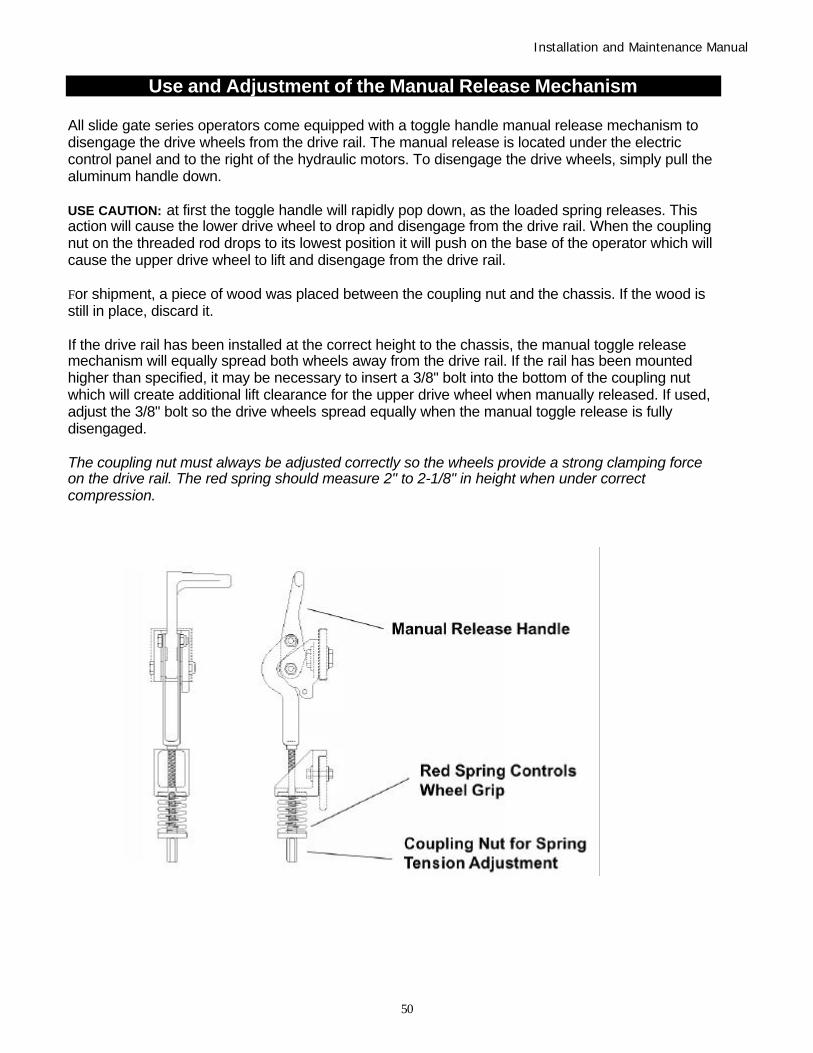
Installation and Maintenance Manual
50
Use and Adjustment of the Manual Release Mechanism
All slide gate series operators come equipped with a toggle handle manual release mechanism todisengage the drive wheels from the drive rail. The manual release is located under the electriccontrol panel and to the right of the hydraulic motors. To disengage the drive wheels, simply pull thealuminum handle down.
USE CAUTION: at first the toggle handle will rapidly pop down, as the loaded spring releases. Thisaction will cause the lower drive wheel to drop and disengage from the drive rail. When the couplingnut on the threaded rod drops to its lowest position it will push on the base of the operator which willcause the upper drive wheel to lift and disengage from the drive rail.
For shipment, a piece of wood was placed between the coupling nut and the chassis. If the wood isstill in place, discard it.
If the drive rail has been installed at the correct height to the chassis, the manual toggle releasemechanism will equally spread both wheels away from the drive rail. If the rail has been mountedhigher than specified, it may be necessary to insert a 3/8" bolt into the bottom of the coupling nutwhich will create additional lift clearance for the upper drive wheel when manually released. If used,adjust the 3/8" bolt so the drive wheels spread equally when the manual toggle release is fullydisengaged.
The coupling nut must always be adjusted correctly so the wheels provide a strong clamping forceon the drive rail. The red spring should measure 2" to 2-1/8" in height when under correctcompression.

Installation and Maintenance Manual
51
Wiring and Control Configuration for DC Operators
If this installation is a 24-Volt DC battery type gate operator, there are a few additional steps that mustbe completed before the system can be functional. Review the installation instructions, step #11 onpage 12 and the connection diagram on pg. 51 (2-battery system) or pg. 52 (4-battery system). Becertain the DC power disconnect switch is turned off before making any connections.
1. Connect the heavy gage wires between the battery enclosure and the gate operator asfollows: Be certain to observe polarity carefully!
a. From the battery enclosure the (+) lead connects to the lug on the large rotary powerdisconnect switch. The (-) lead connects to the lug on the circuit breaker. At the gateoperator the (+) lead connects directly to the lug on the top of the DC electric motor.The (-) lead connects to the bottom lug on the contactor mounted alongside the DCmotor. All lug connections must be tightened very securely since they pass highcurrent to the gate operator.
2. Connect two separate 14-gage circuits between the battery enclosure and the gate operator.One circuit provides the 24 VDC to the gate operator controls and the second circuit isrequired so that the Smart Touch Controller knows that the battery charger is operatingnormally on AC power. Be certain to observe polarity carefully!
a. Connect four wires to the terminal strip in the battery supply labeled: (+)24, (-)24,COM, #21. The 24 Volt (+) and (-) terminals connect to the red (+) and black (-) wiresat the on/off power switch in the gate operator.
b. The COM and #21 terminals connect to the Common Buss and to terminal #21(Charger AC power loss) on the Smart Touch Controller.
3. The Smart Touch Controller User Menu (U4) provides four optional system configurations for24-Volt DC battery type gate operators. Since this is an uninterruptible power supply system,the installer must decide, depending upon customer preference, what is to happen when theAC line power fails. There are four functional choices provided in the User Menu, item [AP_].
Setting 0 (Type A): The operator functions normally until the batteries drop to 21 Volts, thenauto open and lock until the battery voltage recovers to 21.5 Volts. The gate can still bemanually closed only by a Close Pushbutton or an Emergency Close input and will then re-open by any open command until the battery voltage drops to 19 Volts at which time the gateis absolutely locked open, unless moved manually.
Setting 1 (Type B): The operator functions normally until the batteries drop to 21 Volts, thenauto close and lock closed until battery voltage recovers to 21.5 Volts. The gate can only beopened by a special combination of a Stop Pushbutton input, then within 1 second, an OpenPushbutton input. The Fire Department open input can open the gate without the specialPBS enabling pre-input. The gate can be re-closed only by Close Pushbutton and theEmergency Close inputs. When the battery voltage drops to 19 Volts, the gate completes itsfinal cycle and stays in the full open or full closed position, depending upon which cycle waslast.
Setting 2 (Type C): The operator automatically opens five seconds after loss of AC powerand locks open, until AC power is restored. The gate can still be manually closed only by aClose Pushbutton or an Emergency Close input and will then re-open by any open commanduntil the battery voltage drops to 19 Volts at which time the gate is absolutely locked open.
Setting 3 (Type D): Same as type C, except the operator initially does nothing after loss ofAC power, but then locks open after the next open command of any type.

Installation and Maintenance Manual
52

Installation and Maintenance Manual
53

Installation and Maintenance Manual
54

Installation and Maintenance Manual
55

Installation and Maintenance Manual
56

Installation and Maintenance Manual
57
Wire Size SchedulesFor 1/2-hp through 5-hp motors
Supplying a gate operator with the right electrical service is crucial to the way the performance of theoperator the life of its electrical components. If the wire size used is too small, the voltage loss,especially during motor starting, will prevent the motor from attaining its rated horsepower. Thepercent of horsepower lost is far greater than the percentage of the voltage loss. A voltage losscould also cause the control components to chatter while the motor is starting, substantially reducingtheir life due to the resultant arcing. There is no way to restore the lost performance resulting fromundersized wires, except to replace them; therefore it is much more economical to choose asufficient wire size at the initial installation.
The tables on the following page are based on copper wire and allow for a 5% voltage drop. Theampere values shown are the service factor ampere rating (maximum full load at continuous duty) ofthe motor.
Always connect in accordance with the National Electrical Code, article 430, and other local codesthat may apply.
The maximum distance shown is from the gate operator to the power source; assuming that sourcepower is from a panel box with adequate capacity to support the addition of this motor load. Thevalues are for one operator, with no other loads applied to the branch circuit. Avoid placing morethan one gate operator to a circuit, but if you must be certain to reduce the maximum alloweddistance by half.
Low Voltage Control Wiring:
The Smart Touch controller has very sensitive control inputs so the wire size of the control wiring isnot a significant issue. The following is a chart of maximum distances for the controls:
Wire Size Maximum Distance 18 ga 7.0 miles 20 ga 3.5 miles 22 ga 2.7 miles 24 ga 2.0 miles 26 ga 1.0 mile 28 ga 3700 feet

Installation and Maintenance Manual
58

Installation and Maintenance Manual
59

Installation and Maintenance Manual
60

Installation and Maintenance Manual
61
Exploded Parts BreakoutRelated Pump Packs

Installation and Maintenance Manual
62
Exploded Parts BreakoutRelated Pump Packs

Installation and Maintenance Manual
63

Installation and Maintenance Manual
64
LIMITED WARRANTY(Hydraulically Powered Operators)
Hy-Security Gate Operators warrants all of its manufactured products to the end-user to befree of defects in material and workmanship. All hydraulic operators are warranted for aperiod of five years from date of shipment. Slide gate operator drive wheels are warrantedfor a period of two years and batteries in DC operators are warranted for one year from thedate of shipment. Even though included as part of a Hy-Security gate operator, accessoriescarrying another manufacturers name plate, (unless a design component of the gateoperator) shall carry only the warranty of the specific manufacturer.
Any modification made to factory products will void the warranty unless the modificationsare approved in writing by the factory, in advance of the change. This exclusion does notapply to normal installation of approved accessories and/or safety devices. This warrantyshall not apply to equipment which has been improperly installed, subjected to negligence,accident, damage by circumstances beyond Hy-Security Gate Operators' control, orbecause of improper operation, maintenance, storage or to other than normal use orservice.
Labor to install new parts or remove defective parts, travel time, or standby time isspecifically excluded from this warranty. Freight (surface or air) and all other incidentalcosts are NOT covered by this warranty. There are no obligations or liabilities on the part ofHy-Security Gate Inc. for consequential damages arising out of, or in connection with, theuse or performance of this product. Hy-Security Gate Inc. assumes no responsibility forother indirect damages with respect to loss of property, profit or revenue. This LimitedWarranty is valid only in the 50 United States, the District of Columbia and theCommonwealth of Puerto Rico. Implied warranties, including those of merchantability andfitness for a particular purpose or application, are limited to one year from date of shipment.
Defective products that are in warranty should be returned to our factory. At our option, wemay elect to repair or replace, free of charge, any such parts. An invoice will be sent at thetime replacement parts are shipped, and a credit will be issued only after the parts havebeen returned undamaged and accepted as defective. No warranty credits will be allowedwithout written permission from the factory, and the return of the defective part, togetherwith a completed Merchandise Return Form (see our Terms of Sale policy for additionaldetails on the return procedure.) Replacement parts shall carry the remainder of the originallimited warranty or 90 days, whichever is longer.
This Limited Warranty gives you specific rights. You may have others, which vary fromstate to state. This Hy-Security Gate Operators’ limited warranty is in lieu of all otherwarranties expressed or implied. This Limited Warranty supersedes all other warranties.
6/01/01

Installation and Maintenance Manual
65
Index
2-battery Supply for DC Operator drawing 52 Maintenance Schedule 48333 Modular Operator 2 Manual Release Mechanism 49333 Modular Slide Gate Operator drawing 57 Mechanical and Hydraulic Adjustments 13333 MS/E/EX Pump and Electrical Paneldrawing
58
444 Operators 2 Options For User Programmable Output Relays 284-battery Supply for DC Operator drawing 53
Pedestrian Entrapment Protection 8Accessory Compatibility Placement and Use of Pedestrian Entrapment
Sensors32
Available Modes and Features 1-2Rules to Follow For Security Gate Applications 36
Clock Functions 29Components Battery Pack for DCOperator
Slide Gate Cantilever drawing 14-15
Correctional Facilities Operators Slide Gate Loop Layout 38Correctional Facilities Models UserOptional Wiring
27 SmartTouch Controller 2
~Basics of Using 17DC Remote Power Package drawing ~Connecting Master/Slave Pairs 21Detector and Loop Fault Diagnostics ~Controller Inputs 19Detector Basics ~Description of Installer Menu Functions 25-26Detector Logic ~Description of User Menu Functions 24Drive Rail Slide Gate Operation ~Drawing 20
~Installation Configuration 18Entrapment Protection Device Schematic 4/30 ~Installer Menu Functions 23Exploded Parts Breakout ~User Menu Functions 22~DX 54 ~Wiring Control Inputs 19~DS/DE 55 Starting the Gate 1~EX/CX/X1/XS 65 Stopping the Gate 1~LS/SS/CF/E/CE 66
Tools Required for Installation 7General Maintenance 47 Troubleshooting 45-46Getting Started 8
UPS Operators 2Heavy Gate Operators 2 UL 235 Standard Requirements for Entrapment
Protection Devices31
High Speed Operators 2How our Hydraulic Operator Works 8 Vehicle Detector Installation Options 39HY-5A Vehicle Detection Installation 40
Wire Size for Voltage Drop Over Distance 60Important Information Wire Size Schedules 59~Installation 6 Wiring and Control Configurations for DC
Operators50
~for Owners and Users 3Installation 10Installation Preparation and Checklist 9Installing Gate Edge Reversing Sensor 33Installing Photoelectric Sensor 34
Limited Warranty 63Loop Configuration 36Loop Diagnostics 37Low Voltage Control Wiring 59
Hy-Security Gate – Quick Start Instructions

Installation and Maintenance Manual
66

Installation and Maintenance Manual
67
To gain access to the User Menu, press the Menu button when the gate is stopped. The LCDwill scroll through key several items, then stop at the close timer setting [Ct ].
User Menu Options Default DescriptionU1 [Ct 0] Close timer setting 0 0 = timer off or 1 – 99 secondsU2 [hC 0] Momentary Close 0 1= Constant hold Close PB required to close gateU3 [ho 0] Momentary Open 0 1= Constant hold Open PB required to open gateU4 [AP 0] Power loss function 0 0 – 3 (0=Type A, 1 = B, 2 = C, 3 = D) See page 49U5 [ro 0] Radio control option 0 0 = Open only, 1 = Close only when full openU6 [bF 2] Warn before operate 2 0 = none, 1 = 3 seconds before and enables Warn
while operate, 2 = warns before + 2 seconds duringU7 [FA 0] Forced open Alert and
automatic gate reposition0 0 = disabled, 1 sound buzzer (2 pulses/sec) if forced
open for more than four seconds, time out in 30 SecU8 [dA 0] Drift Closed Alert and
automatic gate reposition0 0 = disabled, 1 sound buzzer (2 pulses/sec) if drift
closed and cannot reopen within four seconds.U9 [PE 0] Photo Eye Align Mode 0 0= off, 1 = on (auto off when close limit triggered)U10 [CL 0] Clock set (24 hour type) 0 0= display, 1= minutes, 2= hours, 3= day, 4= monthU11 [Ld 5] LCD Contrast set 5 1 - 9 = Adjusts contrast of the display
To access Installer Menu, press the Open & Reset buttons together while in the User Menu.
Installer Menu Options Default DescriptionI1 [uC 0] Set UL Usage Class 0 0 = gate disabled, Set Class 1 through 4 useI2 [Sh 0] Set Handing of gate 0 0 = gate disabled, r= Right Hand, L = Left HandI3 [Fd 0] Load Factory Defaults 0 0 = disabled, 1 = Load defaults (resets entire menu)I4 [dg 0] Set Master/Slave type 0 0 = solo operator, 1 = Slave unit, 2 = Master unitI5 [Ch 0] Set AC Charger or Solar 0 0 = DC + AC charger 1 = DC + Solar chargerI6 [Fo 0] Enable Fire Dept. Open 0 0 = disabled, 1 = enabledI7 [oC 0] Enable Emergency close 0 0 = disabled, 1 = enabledI8 [SE 3] Inherent Sensor sens. 3 1 – 9 sensitivity (9= least sensitive)I9 [SS 0] Inherent Sensor function 0 1 = stop only (note, functions in usage class 4 only)I10 [LC 0] Leaf delay Close 0 0 = none (1-7) ½ second stepsI11 [Lo 0] Leaf delay Open 0 0 = none (1-7) ½ second stepsI12 [rt 0] Maximum run timer 0 0 – 1 (0= 60 Seconds, 1 = 300 Seconds)I13 [Po 0] Partial Open distance 0 0 = none, or 7 – 99 secondsI14 [EC 0] PEC reverse to open 0 0 = stop only, 1= 2 sec reverse to openI15 [EO 0] PEO reverse to close 0 0 = stop only, 1= 2 sec reverse to closeI16 [gr 0] Edge reverse to open 0 0 = reverse fully open, 1= 2 sec reversal onlyI17 [Sr 1] IES reverse to open 1 0 = reverse fully open, 1= 2 sec reversal onlyI18 [PC 0] Set PEO/ PEC – NO/NC 0 0 = Normally Open, 1 = Normally ClosedI19 [gC 0] Set Edge input – NO/NC 0 0 = Normally Open, 1 = Normally ClosedI20 [tC 1] Time clock/ Interlock input 1 0 = select Time Clock, 1 = select Open InterlockI21 [or 1] OOLD detector function 1 0 = pause only, 1 = enable reversing to openI22 [ir 1] IOLD detector function 1 0 = pause only, 1 = enable reversing to openI23 [dL 1] Vehicle detector logic 1 1-4, 1 = std, 2 & 3 = quick close, 4 = full anti-tailgateI24 [r1 0] User relay 1 option 1 0 = disabled, 1 – 19 = see output options page 22I25 [r2 0] User relay 2 option 6 0 = disabled, 1 – 19 = see output options page 22I26 [r3 0] User relay 3 option 1 0 = disabled, 1 – 19 = see output options page 22I27 [t L 0] Gate Open alert 2 0 = 0 sec, 1=15s, 2=45s, 3=75s, 4=105s, 5=135sI28 [Lt 0] Loitering alert 3 0 = 0 sec, 1=15s, 2=45s, 3=75s, 4=105s, 5=135sI29 [ELd0] Test factory ELD* 0 0 = Run mode, 1 = show freq, 2 = show call level 0-7I30 [iLd0] Test factory IOLD* 0 0 = Run mode, 1 = show freq, 2 = show call level 0-7I31 [oLd0] Test factory OOLD* 0 0 = Run mode, 1 = show freq, 2 = show call level 0-7I32 [SLd0] Test factory SLD* 0 0 = Run mode, 1 = show freq, 2 = show call level 0-7

Installation and Maintenance Manual
68
Troubleshooting
Fault Indication System, LCD Display & Audio Alert Buzzer:
Use this as a quick reference guide to determine the cause of any problem reported on theSmart Touch Controller display. There are three different categories:
Alerts – ALE: Restore function by issuing a new command of any type.Faults – FAL: A stop input is required to restore functionErrors – Err: Pressing the reset button is required to restore function.
Error, Fault, or Alert Status LCD Display Buzzer Chirp SequenceCannot respond due to trippedsensor or in Entrapment mode
Entr 2 chirps/sec every 2 seconds while controlinput is active
Safety Mode Alert SAFE 2 chirps once when in Safety ModeLow 24V Control Voltage Alert Lo24 (ac or dc) N/A (display flashes 1 sec every 5 seconds)Critical Low Power bAdP (ac or dc) N/A (display steady - controls disabled)Dead 24V Battery Alert – DC only bat – dEAd 3 chirps upon any operating commandGate Forced Open Alert ALE1 2 pulses/sec for 30 secondsGate drift closed Alert ALE2 2 pulses/sec for 10 secondsMotor thermal overload Alert ALE4 2 chirps/sec once every 15 secondsBoth Limits Tripped Alert ALE5 2 chirps/sec every 15 secondsLimits not released in 10 seconds ALE6 2 chirps/sec every 15 secondsLoop detector freq change alert ALE7 2 chirps/sec every 15 secondsLoop shorted to ground alert ALE8 2 chirps/sec every 15 secondsLoop open (disconnected) alert ALE9 2 chirps/sec every 15 secondsLoop detector comm. alert AL10 2 chirps/sec every 15 secondsLoop detector failed alert AL11 2 chirps/sec every 15 secondsMaximum Run Fault FAL1 1 chirp once every 15 secondsPhoto eye Fault (supervised) FAL2 2 chirps/sec once per minuteDirectional Motion Error Err1 3 chirps/sec once per minuteDisconnected IES Error Err2 3 chirps/sec once per minuteSerial comm. internal Error Err3 3 chirps/sec once per minute or 3 on Cmd.Serial comm. mast/slave Error Err4 3 chirps/sec once per minuteEEPROM Data Error (factory) Err7 3 chirps/sec once per minuteEEPROM Data Error (installer) Err8 3 chirps/sec once per minuteEEPROM Data Error (user menu) Err9 3 chirps/sec once per minuteMemory Checksum Error FaiL 3 chirps/sec once per minute
The green LED near #24 on the terminal strip is the heartbeat of the processor. This LEDalways blinks brightly, at a steady pace, to indicate normal operation.