Embed Size (px)
Citation preview

hy-gain308 Industrial Park RoadStarkville, MS 39759 USA Ph:(662) 323-9538 FAX: (662) 323655 1
I N S T R U C T I O N M A N U A LGeneral DescriptionThe "Hy-Tower" is an omnidirectional, self-supporting vertical radiator, which operates on10 thru 80 meters. 160 meter operation ispossible with the addition of a loading coil, asshown in Figure 13. The "Hy-Tower" is nowsupplied with stainless steel hardware.
The use of stub decoupling systems allowsband switching on 10, 15, 20, 40, and 80
The stubs isolate various sections of the verticalantenna so that an electrical 1/4-wavelength (orodd multiple of 1/4-wavelength) exists on allbands. On 20 meters, the 80-meter section actsas a 3/4-wave radiator.
The tilting base of the "Hy-Tower" allows theantenna to be completely assembled on theground before it is raised into position. It islight enough for one person to assemble and fortwo people to erect.
Revision 3
AV-18HT“Hy-Tower” Vertical Antenna
10,15,20,40, and 80 Meters
SpecificationsMechanical
Total Height 53 feet (16.15m) (approximately)Tower Construction Galvanized steelWind Survival 75 mph (120.7 kmph)Hardware Stainless steel
ElectricalPattern Characteristics OmnidirectionalGain Unity on 20, 40, and 80 Meters
2dB on 10 and 15 MetersInput Impedance 50 ohmsInput Power 1 kW AM; 2 kW PEP
Pre-AssemblyNOTE: When unpacking your antenna, checkthe inside of all tubing for parts. To conservespace, the smaller items are sometimes putinside larger pieces.
Model 18-HT-S has three (3) 8 foot tower sec-tions and an aluminum tubing mast. For maxi-mum security, the tower section should be setin a concrete base. The concrete must cure forat least three (3) days before the tower is set inplace.
Read the instructions and study theillustrations before beginning your installation.
Qty Type Tool Qty Type Tool
1 Screwdriver-flat blade 1 Open-End Wrench, 7/16"1 Tin Snips (or Lineman's Pliers) 1 Ratchet handle for Socket
Wrenches1 Tape Measure, 50 foot 1 Socket Wrench, 1/2"2 Adjustable Wrenches, 8" 1 Socket Wrench, 9/16"1 Nut Driver, 716" 1 Open or Box End
Wrench, 9/16"
The Model 18-HT -S can be used with 50 ohmcoaxial cable such as RG-213/U or RG-58A/U.Coaxial cable RG-213/U (such as BELDEN8267) is recommended for its lower line lossesand higher power handling capabilities. TheSWR at resonance is less than 1.2:1 and willnot exceed 3.5:1 over the entire range of eachband.Find a convenient location for the 18-HTS"HyTower" antenna. It should be installedaway from any power lines and should be atleast 10 feet from any metallic structure. Besure to allow approximately 50 feet in onedirection from the base for assembly of theantenna and tower.
WARNING
When installing your system, take extremecare to avoid any accidental contact withpower lines or overhead obstructions.Failure to exercise this case could result inserious or fatal injury.
Dig a hole 3 feet square by 3 feet deep for the ;concrete base as shown in Figure 1.
NOTE: The depth of the base foundation willvary depending upon climate conditions. Itshould extend at least 6" below the frost line.It should never be less than 3 feet.
Figure 1Base Foundation Hole

Assemble base assemblies "A" and "B" using3/8"-16 hardware. See Figure 2.
Install the three base insulator assemblies (withpipe legs attached) on the base assemblies,using 1/4"-20 hardware. See Figure 2.
Install the Three (3) 1 1/4" compression clampsonto the pipe legs and position them near theinsulators as 'shown in Figure 2. Tighten theclamps just enough to hold them in position.Refer to Figure 5 for compression clampinstructions.
Install the 1/4"-20 x 2 1/2" hex head bolts andnuts on the bottom of each base insulatorassembly. This bolt will help to anchor eachleg in the concrete. See Figure 2.
Figure 2Tower Base

Pour a standard mix of concrete (five partssand, one part cement) into the hole until itreaches ground level. Vibrate the concreteduring the pouring to eliminate voids.
NOTE: For extra security, steel reinforcingrods can be added to the base before theconcrete is poured.
Insert the base assembly, with legs attached,into the concrete base until approximately sixinches remain above the concrete, as shown inFigure 3. Position the assembly so that thetower can hinge on base assembly "A".
CAUTION
The base assembly must be assembledlevel so that the tower will be verticalwhen it is installed. Support the baseassembly above the concrete in the mannershown in Figure 3 while the concrete iscuring.
An easy method to ensure a level baseinvolves using a low-cost string level.Loop a length of string through the three(3) holes on the standoffs above the two(2) base assemblies. Apply tension untiltaut, then tie it off. Hook the string levelonto each part of the string and adjust thetower base so that each string is level.
Figure 3Tower Base Installation

Assembly of the TowerRemove the shipping straps from the tower as-sembly.
Assemble the three tower sections by placingeach succeeding smaller tower section into thenext larger section.
Secure the tower legs using two (2) 3/8" x 3/4"hex bolts per splice. The nuts (12) and bolts (12)are packed in the carton containing tubes andhardware.
Install the tower leg hinges and braces onto twotower legs as shown in Figure 4.
Installation of Tubing ClampsSelect the proper size tube clamp as shown inthe chart. (See Figure 5B). When installing theclamps, place the clamp near the tube end withthe top of the clamp over the slot in the tube asshown in Figure 5A.
After adjustment of the tubing lengths, tightenthe clamp with a 5/16 inch nut driver, socket, oropen end wrench until the tubing will not twistor telescope.
Figure 5AInstallation of Tubing Clamps

Figure 5BTubing and Compression
Part Description FitsNo. Tubing
Sizes358756 Clamp, Size #6 7/16",1/2",
all stainless steel 5/8" and 3/4"5/16" hex head screw
Part Description FitsNo. Tubing
Sizes358757 Clamp, Size #10 3/4", 7/8" and 1"
all stainless steel5/16 hex head screw
Part Description FitsNo. Tubing
Sizes358758 Clamp, Size #16 1",11/8"
all stainless steel and 11/4"5/16 hex head screw

Assembly of Vertical RadiatorAttach one 4" metal angle to the lower -towerplate and one to the upper tower plate using two(2) 1/4"-20 x 3/4" screws for each angle. Do nottighten the screws at this time.
Select the 2" x 75" length of aluminum tubingand place the two (2) 2" ID x 3 7/8" insulatorsover the end of the tubing which has the metalsleeves inserted in it.
Select the two (2) U-bolts and spacerinsulators and place them in the holes providedon the 4" metal angles attached to the toptower section. See Figure 6.
Adjust the insulators so that they are ap-proximately 28 3/8" apart, with the bottom oneapproximately 1 1/2" from the end of thetubing (the end with the metal sleeve).
Item ItemNo. Description No. Description7 Angle, vertical element, 1" x 1" x 4" 38 U-Bolt, 5/16" x 3" x 3 11/16"17 Insulator, 2" I.D. x 3 7/8" 39 Lockwasher, split, 5/16", stainless steel26 Bolt, 1/4"-20 x 3/4", hex head, stainless steel 40 Nut, 5/16"-18, hex33 Lockwasher, 1/4", internal, stainless steel 58 Insulator, vertical element spacer, 1" x 4"35 Nut, 1/4"-20, hex, stainless steel 61 Assembly, tube with dowel, 2" x 75"
Figure 6Top Element Installation

Slide the 2" x 75" length of tubing (the endwith the insulators attached) through the upperand lower plate of the top tower section asshown in Figure 6. Do not tighten the U-bolts
Select the 2" x 51" section of tubing and slip thedrilled end over the swaged end, of the 2" x 75"piece of tubing. Align the holes and secure withthe 1/4"-20 x 2 1/2" screw, nut and lockwasheras shown in Figure 7.
Select the reducer clamps and install on the endof the 2" tubing, using #10 x 1/2" screws, lock-washers and nuts. Do not tighten at this time.
Carefully adjust the partially assembled verticalradiator until you measure 90 1/2" from the topedge of the top tower plate to the top edge ofthe reducer clamp. Refer to Figure 7.
Position the two insulators on the 2" tubing asshown in Figure 6, then tighten the U-boltsevenly. The insulators must be positioned asshown to properly insulate the tubing sectionfrom the tower.
Select a #10 tubing clamp and slip it over theend of the 1 1/8" tube. Refer to Figure 5A forproper placement.
Select the 7/8" x 72" piece of tubing and slipthe unswaged end into the swaged end of the 11/8" tube. Measure 64 1/2" (163.8 cm) from theend of the 1 1/8" tubing to the end of the 7/8"tubing. Tighten the clamp. See Figure 7.
Slip a #6 tubing clamp over the end of the 7/8"tubing. Tighten slightly.
Select the 5/8" x 48" piece of tubing and slipthe unswaged end into the 7/8" tubing. Measure42" (106.7 cm) from the end of the 7/8" tube tothe end of the 5/8" tube. See Figure 7.
Slip a #6 tubing clamp over the end of the 5/8"tubing. Tighten slightly.
Select the 7/16" x 68" piece of tubing and slip itinto the 5/8" tube. Measure 66" (167.6 cm) fromthe end of the 5/8" tube to the end of the 7/16"tube. See Figure 7.
Slide the metal angles in the elongated holes toposition the tubing section until the tube is per-fectly aligned with the axis of the tower.Tighten the screws securely!
NOTE: You may wish to assemble theremainder of the vertical radiator separately andinstall on the antenna immediately beforeraising the antenna to its vertical position. Thiswill avoid allowing the tubing to droop andpermanently "set" in this condition.
Check the overall dimension of the verticalradiator. It should be 27'9 3/8" (3.47 m) fromthe top of the upper tower plate to the end of theradiator. If it is not, adjust the 7/16" tubing ac-cordingly. Now tighten the compression clampssecurely.
Place a 7/16" caplug on the end of the verticalradiator.
Select the 1 1/4" x 48" piece of tubing, mark at9" from the end and slip it 9" into the 2" tubeassembled in the tower, so that 36 5/8" (93.02cm) remain exposed above the reducer clamp.See Figure 7.
Select a #16 tubing clamp and slip it over theend of the 1 1/4" tube. Select the 1 1/8" x 38"tube and insert it into the 1 1/4" tube so theswaged end is 33 3/4" (85.72 cm) from the endof the 1 1/4" tube. See Figure 7.

Installation of 15-Meter Stub Installation of 10-Meter StubSelect a 7/16” x 60” piece of tubing and fastenone end to one leg of the base tower section usingthe clamps and shorting strap, as shown in Figure8. Position the stub 67” (see Figure 16) from thebottom edge of the tower leg to the bottom edgeof the 7/16” tube. Refer to Figure 8 for dimen-sions and Figure 10 for installation of clamps andshorting strap.
Assemble another leg clamp, insulator and spliceand install the second 7/16” x 60” section oftubing onto the 15-meter stub as shown in Figure8.
Select the remaining 7/16” x 60” piece of tubingand fasten one end to one of the remaining towerlegs, as shown in Figure 9, using a set of legclamps and a ,shorting strap.
Position the bottom edge of the stub 160” (seeFigure 16) from the bottom edge of the lowertower leg. Refer to Figure 9 for dimensions andFigure 10’ for installation of the clamps andshorting strap.
Select the 7/16” x 38” section of tubing andinstall as shown in Figures 9 and 10.
Install a leg clamp, insulator and tubing clamp Install a leg clamp, insulator and tubing clamp
Select the 5/16”x 23” section of tubing and slip itinto the 7/16” tuba. Adjust to either Phone (19”)or CW (21-1/4”) dimension as shown in Figure 8.Install a ½” compression clamp, line up thescrew with the hole on the 7/16 tube and tightensecurely.
Select the 5/16” x 9-1/2 section of tubing and slip itinto the 7/16” tubing. Adjust for Phone (3”) or CW(5”) dimension as shown in Figure 9. Refer toFigure 16, VSWR Charts.Install a ½” compression clamp, line up the screwwith the hole on the 7/16 tube and tighten
NOTE: Typical VSWR curves are shown in Fig-ure 16. The 10- and 15-meter stubs require twosettings to cover the bands with less than 2:1VSWR. Use the VSWR curves to help you decidewhich setting is best for your particular applica-tion.
Placestub.
5/16” caplug on the end of the 15-meter
NOTE: The 10-and 15-meter stubs can be setindependently. One can be set for CW and onefor Phone, or they can both be adjusted for thesame mode. If you wish to adjust a stub for anyparticular frequency within an band, this can bedone experimentally.
Place a 5/16”caplug on the end of the 10-meterstub.

Figure 8
15-Meter Stub
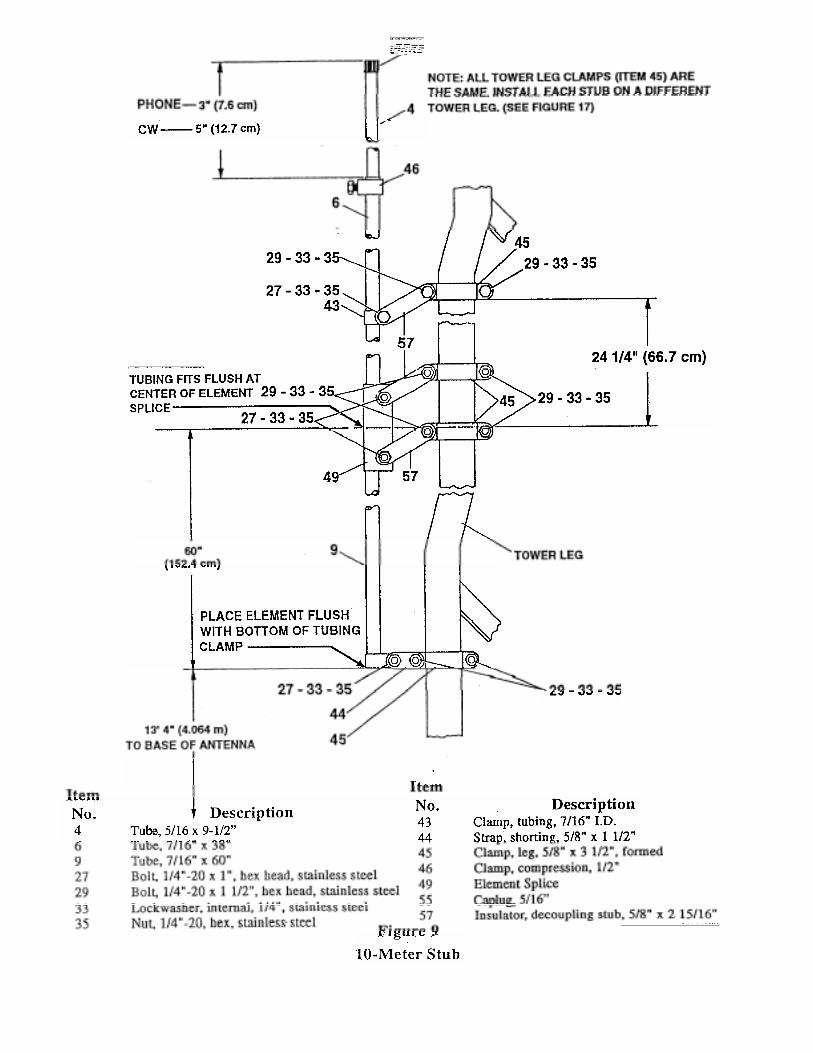

Figure 10Tower Leg Clamp
Installation of 40-Meter Stub
NOTE: Each stub must be attached to aseparate tower leg. The 40-meter stub (nowbeing assembled) must be attached to the verytop of the tower section. See Figure 11.
Select the 7/16" x 68" tube and slip it into the5/8" tube. Measure 90" for both Phone andCW, as shown in Figure 11, then tighten thecompression clamp securely.
Select the 5/8" x 24" tube and install it ontower using two leg clamps and two shortingstraps spaced 5 1/2" apart, as shown in Figure11.
Slip a #6 tubing clamp onto the 5/8" tube.Tighten slightly.
Place a 7/16" caplug on the top of the 40-meterstub.
NOTE: The higher tubing clamp can beloosened and the lower shorting strap hingedto bring the 40-meter stub into a verticalposition.

Figure 11
40-Meter Stub

Installation of 80-Meter Wire
Select the 80-meter wire and install it in thecenter of the tower with the looped end at thetop of the tower.Select the 3/8" spacer tube and attach the 80-meter wire to the 2'.' tube as shown in Figure12.
Install the eyebolt at the tower base assemblyas shown in Figure 12. Adjust for maximumheight. The 80-meter wire will attach to thiseyebolt after the tower is tilted into place.

NOTE: To cover the low end of 80 meters (seeFigure 12) it will be necessary to add aloading coil as previously explained andshown in Figure 13. This coil can be used toextend the 80 meter band or add 160 meter
Figure 1380 Meter and 160 Meter Coil Installation

160 Meter Operation Erection of Tower
By adding one of two available kits, 160 meteroperation can be added to the 18HT `Ey-Tower".these kits are available fromHy-Gain, 308 Industrial ParkRoad Starkville, MS 39759USA.
Kit Number LC-160Q is a loading coil that canbe added at the tower base as shown in Figure13. This coil is four turns per inch, 3" I.D. by10" long. After the coil is installed, the wire clipshould be attached at the point that gives mini-mum VSWR at the frequency you wish tooperate on. This coil should be bypassed whenoperating on 20 or 75 meters.
WARNING
When using the LC-160Q Modification Kitadded to the 18-HT on 160 meters, do notexceed 150 watts output power (300 WP.E.P. out). Power levels in excess of thislimit will cause the antenna to arc.
Kit Number MK-160 is a 40 meter trap and wireassembly that can be added at the top of thetower as shown in Figure 17. This kit willprovide a greater band width and a higherpower rating than the LC-160Q. It also providesfully automatic band switching from 160through 10 meters.
Install the tower legs with hinges attached ontothe base assembly. Do not tighten screws at thistime.
WARNING
When installing your system, take extremecare to avoid any accidental contact withpower lines or overhead obstructions.Failure to exercise this could result inserious or fatal injury.
Lift the antenna and walk it into a vertical posi-tion. Install the remaining leg brace and bolt theleg to the base assembly as shown in Figure 14.Tighten all screws securely.
Insert the 80-meter wire through the eyebolt in-stalled at the tower base. Wrap the wire arounditself several times to insure a good tightconnection. Solder the connection for the bestelectrical connection.
Adjust the eyebolt until the wire is taut.
Attach the solder lug on the 80-meter wire tothe tower base assembly as shown in Figure 14.
Figure 14Tower Leg Attachment to Base

Feedline Attachment and GroundingInstall two ground rods at each tower leg.Space them 24" from the leg with 18" betweenthe two rods as shown in Figure 15. Use 1/2" x8' copper clad steel rods (not supplied) for agood ground.Attach each rod to a pip leg..using #10 orlarger copper wire (not supplied). Now connectthe three pipe legs together as shown in Figure15.
Weatherproof the coaxial cable using Coax-Seal© or some similar substance to preventwater from entering and ruining the coax.
The overall efficiency of the 18-HT -S can beimproved by adding a radial system. The nextsection describes how to install a radialsystem.
Strip your coaxial cable and attach the centerconductor to the tower base using the holeprovided as shown in Figure 15. Attach thebraid to a pipe leg. Cover the exposed coaxcable dielectric to prevent U.V. cracking. Coax-Seal® is a registered trademark of Universal Electronics, Inc.

Installation of RadialsThere is no need to make radials exactly 1/4"wavelength long for the 18-HT-S Hy-Tower. Infact, the only case where you should have 1/4"wavelength radials would be for approximately90 radials. This differs rather dramatically fromthe case of a Ground-Plane antenna whereresonant radials are installed above ground.Since the radials of a Ground-Mounted verticalare actually on, if not in, the ground, they arecoupled by capacitance or conduction to theground, and thus resonance effects are notimportant. Basically, the function of radials isto provide a low-loss return path for groundcurrents. The reason that short radials aresufficient, when few are used, is that at theperimeter of the circle to which the groundsystem extends, the radials are sufficientlyspread apart. Most of the return currents arealready in the ground between the radials ratherthan in the radials themselves. As more radialsare added, the spaces between them are
Since the 18-HT -S Hy-Tower is a multi-band,vertical antenna, the radial system should beoptimized on the lowest frequency you plan touse. Higher frequencies will benefit equallyfrom the ground system, while lowerfrequencies will not show as much
To determine the optimum radial installationfor your 18-HTS Hy-Tower, you must firstdecide what is the limiting factor for your
1. Cost of radiali
2. Land available for radials
3. Efficiency of your antenna
Table 1 shows some various ground systemconfigurations. System A is the least costly andthe least efficient. System F is the mostexpensive, takes the most land and is the mostefficient.

A B C D E F
Number of Radials 16 24 36 60 90 120
Length of each radial inwavelengths .1 .125 .15 .2 .25 .4
Spacing of radials in degrees 22.5 15 10 6 4 3
TOTAL length of radial wire 1.6 3 5.4 12 22.5 48
installed, in wavelengthsPower gain (dB) due to 3.0 3.6 4.0 4.7 5.2 6.0
increased efficiencyRadiation take-off angle in 30 30 30 30 28 24
degreesFeed-point impedance in ohmswith a 1/4-wave radiating element 52 46 43 40 37 35
Radial end buried YES YES YES NO NO NO
Table 1Optimum Ground System Configuration
NOTE: TABLE 1 is optimized for poor earthconditions. Conductivity = 0.0001Siemens/meter and the Relative DielectricConstant = 7. Better earth conditions willincrease the power gain and lower the take-offangle for systems A-D.
Systems E and F will not be affected as much,except for additional lowering of the take-offangle by as much as 5 to 8 degrees. See pages28-30 of "QST" June, 1985 for moreinformation on radial systems for verticals.

Figure 16VSWR Charts

Figure 17Overall View of 18-HT-S
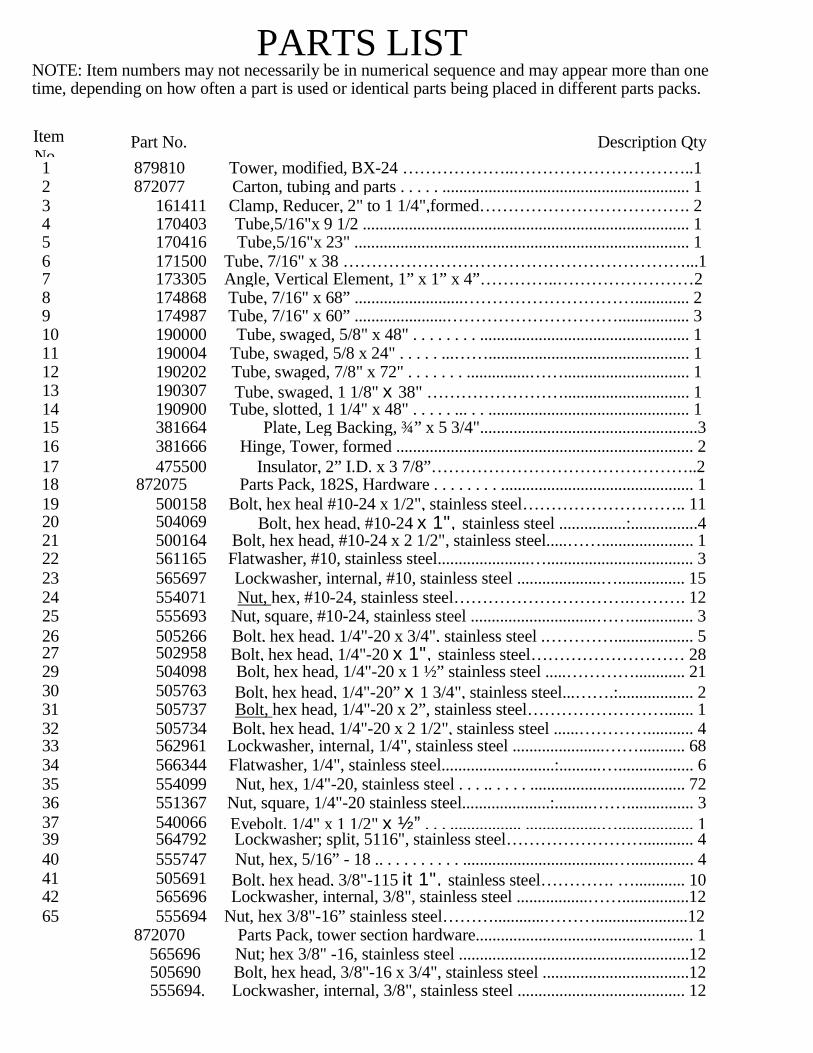
PARTS LISTNOTE: Item numbers may not necessarily be in numerical sequence and may appear more than onetime, depending on how often a part is used or identical parts being placed in different parts packs.
ItemNo
Part No. Description Qty1 879810 Tower, modified, BX-24 ………………..…………………………..12 872077 Carton, tubing and parts . . . . . ........................................................... 13 161411 Clamp, Reducer, 2" to 1 1/4",formed………………………………. 24 170403 Tube,5/16"x 9 1/2 .............................................................................. 15 170416 Tube,5/16"x 23" ................................................................................ 16 171500 Tube, 7/16" x 38 ……………………………………………………...17 173305 Angle, Vertical Element, 1” x 1” x 4”…………..……………………28 174868 Tube, 7/16" x 68” ..........................…………………………............. 29 174987 Tube, 7/16" x 60” ......................…………………………................. 310 190000 Tube, swaged, 5/8" x 48" . . . . . . . . .................................................. 111 190004 Tube, swaged, 5/8 x 24" . . . . . ...……................................................ 112 190202 Tube, swaged, 7/8" x 72" . . . . . . . ...............…….............................. 113 190307 Tube, swaged, 1 1/8" x 38" …………………….............................. 114 190900 Tube, slotted, 1 1/4" x 48" . . . . . ... . . ................................................ 115 381664 Plate, Leg Backing, ¾” x 5 3/4"....................................................316 381666 Hinge, Tower, formed ....................................................................... 217 475500 Insulator, 2” I.D. x 3 7/8”………………………………………..218 872075 Parts Pack, 182S, Hardware . . . . . . . . .............................................. 119 500158 Bolt, hex heal #10-24 x 1/2", stainless steel……………………….. 1120 504069 Bolt, hex head, #10-24 x 1", stainless steel ................:................421 500164 Bolt, hex head, #10-24 x 2 1/2", stainless steel.....……...................... 122 561165 Flatwasher, #10, stainless steel......................…................................... 323 565697 Lockwasher, internal, #10, stainless steel ....................…................ 1524 554071 Nut, hex, #10-24, stainless steel………………………….………. 1225 555693 Nut, square, #10-24, stainless steel ..............................……............... 326 505266 Bolt, hex head, 1/4"-20 x 3/4", stainless steel .…………................... 527 502958 Bolt, hex head, 1/4"-20 x 1", stainless steel……………………… 2829 504098 Bolt, hex head, 1/4"-20 x 1 ½” stainless steel .....…………............ 2130 505763 Bolt, hex head, 1/4"-20” x 1 3/4", stainless steel...…….:.................. 231 505737 Bolt, hex head, 1/4"-20 x 2”, stainless steel……………………....... 132 505734 Bolt, hex head, 1/4"-20 x 2 1/2", stainless steel ......…………........... 433 562961 Lockwasher, internal, 1/4", stainless steel ......................……........... 6834 566344 Flatwasher, 1/4", stainless steel...........................:..........….................. 635 554099 Nut, hex, 1/4"-20, stainless steel . . . .. . . . . ..................................... 7236 551367 Nut, square, 1/4"-20 stainless steel.....................:.........……................ 337 540066 Eyebolt, 1/4" x 1 1/2" x ½” . . . ................. ..................….................. 139 564792 Lockwasher; split, 5116", stainless steel……………………............ 440 555747 Nut, hex, 5/16” - 18 .. . . . . . . . . . ....................................…............... 441 505691 Bolt, hex head, 3/8"-115 it 1", stainless steel…………. …............ 1042 565696 Lockwasher, internal, 3/8", stainless steel .................……................1265 555694 Nut, hex 3/8"-16” stainless steel………............………......................12
872070 Parts Pack, tower section hardware.................................................... 1565696 Nut; hex 3/8" -16, stainless steel .......................................................12505690 Bolt, hex head, 3/8"-16 x 3/4", stainless steel ...................................12555694. Lockwasher, internal, 3/8", stainless steel ........................................ 12

PARTS LIST (continued)
Item# Part # Description872077 Carton, tubing and parts (continued)872076 Parts Pack 182S, Clamps…………………………………………..1
38 547225 U-Bolt, 5/16" x 3" x 3 11/16"...........................................................243 161851 Clamp, Tubing, 7/16" LD.................................................................444 163378 Strap, Shorting, 5/8" x 1 1/2"...........................................................645 163300 Clamp, Leg, formed 5/8" x 3 1/2"..................................................2046 165123 Clamp, Compression, 1/2"................................................................247 171329 Clamp, Tubing 5/8" LD.....................................................................248 168680 Clamp, Compression, 1 1/4".............................................................349 171548 Element Splice...................................................................................250 173221 Tube, Spacer 3/8" x 17/8 "................................................................151 358756 Clamp, #6 Tubing, stainless steel ................................................... 352 358757 Clamp, #10 Tubing, stainless steel ..................................................153 358758 Clamp, #16 Tubing, stainless steel ..................................................154 (Not Used)55 765-1031 Caplug, 5/16......................................................................................256 455644 Caplug, 7/16", black..........................................................................257 465416 Insulator, decoupling stub, 5/8" x 2 15/16" ....................................658 471056 Insulator, Vertical Element Spacer, l" x 4".....................................259 872451 Base Tube Assembly.................….....................................................360 872464 Wire Assembly, 80 Meter..................................................................161 872465 Tube Assembly with dowel, 2" x 75" …...........................................162 874687 Tube/Shim Assembly, 2" x 51”...…..................................................163 882782 Base Assembly "B”..........................................................................164 882783 Base Assembly "A”........................................................................1
Converting English Measurements to Metric 1 inch (1") = 2.54 cmUse this scale to identify lengths of bolts, 1foot (1')=30.48 cmdiameters of tubes, etc.. The English inch (1")and foot (1') can be converted in this way. Example: 42" x 2.54= 106.7
FRACTION AND METRIC EQUIVALENTSFOR ONE INCH
Fractional FractionalInch Millimeters Inch Millimeters1/16 1.588 9/16 14.2881/8 3.175 5/8 15.8753/16 4.7001 1/16 17.4631/4 6.350 3/4 19.0505/16 7.937 13/16 20.6383/8 9.525 7/8 22.2257/16 - 11.112 15/16 23.8131/2 12.700 1 25.400

The Hy-tower base assembly has been changed,Substitute this drawing for figure 2 on page 3.
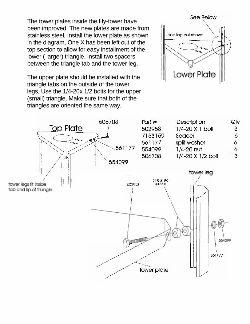
The tower plates inside the Hy-tower havebeen improved. The new plates are made fromstainless steel, Install the lower plate as shownin the diagram, One X has been left out of thetop section to allow for easy installment of thelower ( larger) triangle. Install two spacersbetween the triangle tab and the tower leg,
The upper plate should be installed with thetriangle tabs on the outside of the towerlegs, Use the 1/4-20x 1/2 bolts for the upper(small) triangle, Make sure that both of thetriangles are oriented the same way,

The following Hy-Gain verticals are welladapted for the phasing arrangementsshown in this reports
MODEL 18HT-S HY-TOWERThe 18HT-S is a multi-band vertical antennawith automatic band selection of 10-80 metersby means of a unique stub decoupling system.The Hy-Tower with a base loading coiloperates efficiently on 160 meters. The systemis foolproof, fed directly with a single 50 ohmcoax. No guys are required for the 24 feet high,self-supporting tower. The top mast extendsthe height to 50 feet. Two units make an idealphased array.
MODEL 18AVT/WB-S
The 18AVT/WB-S is a multi-band trap verticalfor 10 through 80 meters. It is completely fac-tory pre-tuned and exhibits an extremely lowangle DX radiation pattern. It is easy to as-semble, light weight which one man can install.A single 50 ohm coaxial feedline is required.Two or three 18AVT/WB-S's make anexcellent phased array.
ADDENDUM AMATEURPHASING
ENGINEERING REPORT
PHASED MULTI-BANDVERTICALS for ADDITIONAL GAIN andLOW ANGLE RADIATION
INTRODUCTION

MODEL 14AVQ/WB-SThe 14AVQ/WB-S is a self supporting multi-band trap vertical for 10 through 40 metersand is completely factory pre-tuned. It is theworld's most popular ham antenna with anoverall height of 19 feet. The antenna isthoroughly weatherproofed and has a lowangle DX radiation pattern. It may be groundmounted or installed on "Roof Top" with aradial system.
MODEL 12AVQThe 12AVQ is a self supporting 13 1/2 footmulti-band trap vertical for 10, 15 and 20meters. Completely factory pre-tuned withSWR of 2:1 or less with a low angle DX radia-tion pattern. The antenna has a new fiberglassimpregnated styron base insulator. It may beground mounted with earth acting as the"image antenna" or installed on the roof usinga radial system.
Increased activity on 80 and 40 meters hascreated a need for an antenna with power gainand directivity. Doublet and long wireantennas are no longer effective due toincreased QRM. At these low frequencies, theradiation system must be lengthy and heightabove ground is extremely important to obtainthe "low" angle of radiation needed for DX.
DESCRIPTION
Beams are excellent, but require a large sup-porting tower and "hefty" rotating system.Inverted V dipoles and slopers require a largetower and plenty of property.
The vertical "phased array", the answer for"DX" on these frequencies combine gain,directivity and low angle radiation, the threemost important DX factors in a communicationinstallation. The vertical is well known for itslow angle characteristics. When you combinetwo identical verticals, properly spaced andphased, the resultant is a concentrated low angleof energy and a power gain. These antennas canbe so arranged to give a definite effect on eitherone or two favorite bands or all band coveragewith some pattern compromise and slight lossof gain.The following data was experimentally derivedon the Telex/Hy-Gain test range. Due to themany factors that vary and influence theperformance of an antenna, such as groundingand close proximity of surrounding objects,etc., Telex/Hy-Gain cannot guarantee aninstallation to perform or exhibit the samecharacteristics as outlined in this report.However, many Amateurs are now successfullyusing these arrangements. Commercialbroadcast stations have been using a similarphasing arrangement for years.
Part 1 - SINGLE BAND
BI-DIRECTIONAL ARRAY(Four Quadrants)
THEORY' OF OPERATIONTwo identical vertical antennas can beinstalled as a phased array. When excited byRF energy, gain is achieved by control of thedirectional pattern. This direction patterncontrol results in added gain by sharpeninglobe patterns and concentrating the radiatedenergy at very low angles. Signal flutter isreduced and reception is vastly improved.
Phased arrays will reduce installation height re-quirements and still maintain low angleradiation.
Most effective spacing for a bi-directionalarray is 1/2 wave length. When two verticalsare excited in phase the radiation is broadsideto the plane of the verticals, offeringsubstantial gain and bi-directionalcharacteristics. Side nulls offer excellent signalcancellation to the undesired direction.

Y
When excited "out of phase" these same verti-cals can be made to give an "end fire" or bi-directional pattern in the opposite directionthrough the plane of the verticals. This thennulls out signals in the opposite directions.More gain is exhibited by the broadsidepattern over the "end fire" arrangement, butthe "end fire" arrangement offers a widerfrontal pattern.Both arrangements offer an excellent ad-vantage over a single vertical since eitherphasing combination exhibits noticeablesignal gain with side attenuation of undesiredsignals. This added gain and low anglevertical directivity is the advantage of thephased array.
"ENDFIRE" GAIN 23 dB
Phased verticals may be spaced either onequarter wave or one half wave dependingupon gain and directional characteristics. Thenulls of the phased array are extremely sharpand very pronounced. Typical arrangements ofphased arrays and their electricalspecifications are illustrated below.

Typical Insta720
Pattern width, half power pointsGain over single verticalSide attenuationImpedanceDirectional characteristics
SPECFICATIONSBroadside End Fire
60 degrees 80 degrees3.86 dB 2.3 dB30 dB 20 dB
50 Ohms 50 OhmsBi-Directional Bi-Directional
Figure 2llation Phased (2) 18 HT 40 Meters0 KHz Design Frequency

CARDIOID ARRAY(Uni-directional)
When two or three identical verticals are ex-cited directly and fed 90 degrees out of phasewith a spacing of 1/4 wave length, a cardioidpattern results. This pattern may be switched ineither direction. By inserting a 1/4 wave lengthdelay line the antenna will "fire" or be directiveto that particular element. .: TWO VERTICALS
Figure 3Cardioid-Unidirectional With Two Selectable Directions
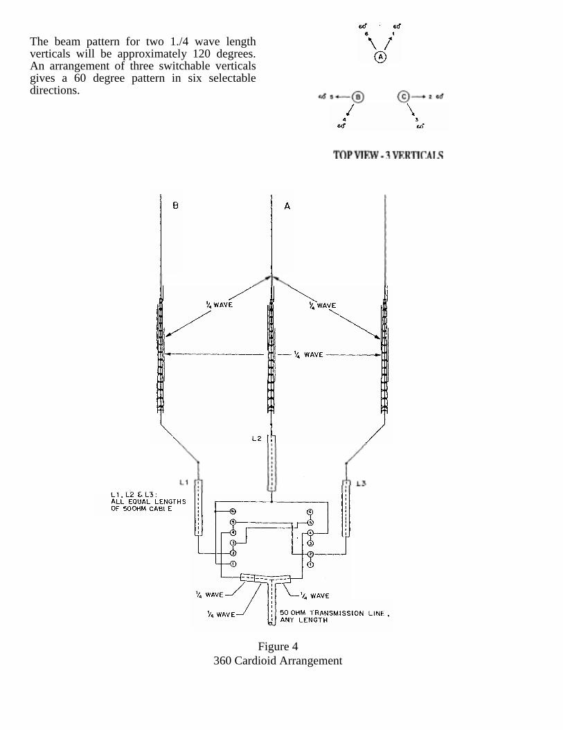
The beam pattern for two 1./4 wave lengthverticals will be approximately 120 degrees.An arrangement of three switchable verticalsgives a 60 degree pattern in six selectabledirections.
Figure 4360 Cardioid Arrangement

The 1/4 and 1/2 wave transformers, identified as L3, L4 and L5 are calculated from thelowing formula:
1/4 wave 246000 x vel.f
vel. factor - reg. coax.0.66frequency (in KHz)
EXAMPLE:
1/4 wave at 7200 KHz = 246000 / 7200 = 34.1634.16x.7525.62
1/4 wave = 25.62ft.
P A R T 2 - M U L T I - B A N D O P E R A T I O N
M U L T I - B A N D I N G RADIATION PATTERN:Multi-banding is easily accomplished bychoice spacing two identical verticals. (referto charts A,B, and C and associated Figures 1through 5) Switchable 1/4 wave length and 1/2wave length phasing cables must be employedfor each band. These cables can be placed inthe station in any suitable fashion along with amanual switching arrangement or relaysystem.
Consideration must be given to the fact that 1/2wave spacing (optional) is ideal for phasing.When multi-banding with close and wide spac-ing, compromise radiation patterns must beexpected. In most cases a choice spacing serves3 bands most effectively with good directionalcharacteristics, added gain and low angle per-formance.
E L E C T R I C A L S P E C IFICATIONS:
VSWR: Exceptionally low SWR is present with a phased array. If phasing lines arecorrectly measured and the terminal impedance of each antenna is very close to 50 Ohms:Typical SWR: Broadside 1.2:1, Endfire 1.4:1, Cardioid 1.2:1.
P H A S I N G L I N E S :
Two Phased Verticals Three Phased VerticalsPattern Width, half power points 120 degrees 60 degreesGain over single vertical 4.5 dB 4.5 dBSide attenuation 20 dB 20 dBRear attenuation 30 dB 30 dBImpedance 50 Ohms 50 OhmsDirectional Characteristics Uni-directional Uni-directional

OPTIONAL SPACING SWITCHES & CONNECTORSVarious antenna spacings may be selectedfrom charts A, B, and C, for single band, duoband or multi-band arrangements. Associatedradiations patterns for a specific spacing isshown in Figures 1 through 5 for each band.
If the 3/4 wave length patterns are notdesirable, a single vertical only can be switchedin use to obtain an omnl-directional pattern.
INSTALLATIONThe vertical antenna requires a minimumamount of space. Ground mounted or elevatedarrays are easily installed.
Antenna placement and orientation is a mostimportant factor when planning maximum ef-fectiveness is desired directions. Each verticalshould be installed in the clear relatively free ofsurrounding objects in order to maintain itsdesign 50 Ohm terminal impedance.
Each antenna must be mounted at the sameheight on or above ground and be so arrangedaccording to their radiation pattern to offerdesired directivity.
The phased array is primarily designed for longrange and DX communications. In cases whereclose and medium distance contacts arehampered by the array's low angle characteris-tics and a higher angle is required, switchingarrangements can select one vertical for thiscoverage.
Low loss constant impedance type coaxialswitches and connectors should be used whensplicing phasing lines. B&W multi-position,single or multi-gang coaxial switches with Am-phenol coaxial cable and "T' connectors arerecommended.
FIELD TESTSActual field tests comparing one vertical to thephased array results in doubling the receiverssensitivity and offering up to 12 dB of signalincrease. An attenuation of up to 30 dB isnoticeable on the phased verticals with halfwave spacing. With quarter wave spacing, upto 20 dB cardioid, and 30 dB front-to-back at-tenuation can be obtained.
"End Fire" directivity offers a larger area ofradiation at slightly reduced gain as comparedto the broadside arrangement. The "broad-side" arrangement is recommended forcommunications at greater distances whereasthe "endfire" arrangement would be so ar-ranged to cover a larger area ofcommunications. Special attention to the coaxphasing line lengths and their properplacement is of utmost importance.

A. 80 meter bi-directional pattern (all SW positions 3) referto Figure 1, Part 2 "Radiation Patterns"
NOTE: Due to close electrical spacing (1/4 wave) on80 meters for Broadside (position 1) and Endure(position 2) the SVWR may be somewhat higher than1/2 wave spacing. SW3 selects direction
B. 40 meters all switches in position 1 selects Bi-Directional patterns. Use SW2 for broadside (position1) Endfire (position 2).
C. All switches in position 2 selects cardioid pattern. SW4selects direction of cardioid pattern.
NOTE: All connecting lines are exaggerated in length. Theselines must be direct and short as with any coax hook-up prac-tice.
Figure 5Typical installation (2) 18HT-S Phased for 80 and 40
Meters Selectable Broadside and Endfire Patters on 40Meters Selectable Broadside and Endfire Patterns on 80Meters Selectable 2 Directions Cardioid on 80 Meters

Note: Corralate Patterns to spacing used in installation
Figure 6Radiation Patterns - Typical Spacing For Broadside And Endfire Arrangements