Embed Size (px)
Citation preview
8/15/2019 HW5 2016 15512006
http://slidepdf.com/reader/full/hw5-2016-15512006 1/84
Halaman 1 dari 2
Tugas 5 KL- 4220 PIPA BAWAH LAUTDosen : Prof. Dr. Ir. Ricky Lukman Tawekal, MSE/ Eko Charnius Ilman, ST, MT
Diberikan : Se lasa, 16 Februari 2016Dikumpul : Senin, 29 Februari 2016 (Jam 7.00 WIB Pagi sebelum kuliah dimulai)
Nama : ______________________________________
NIM : ______________________________________
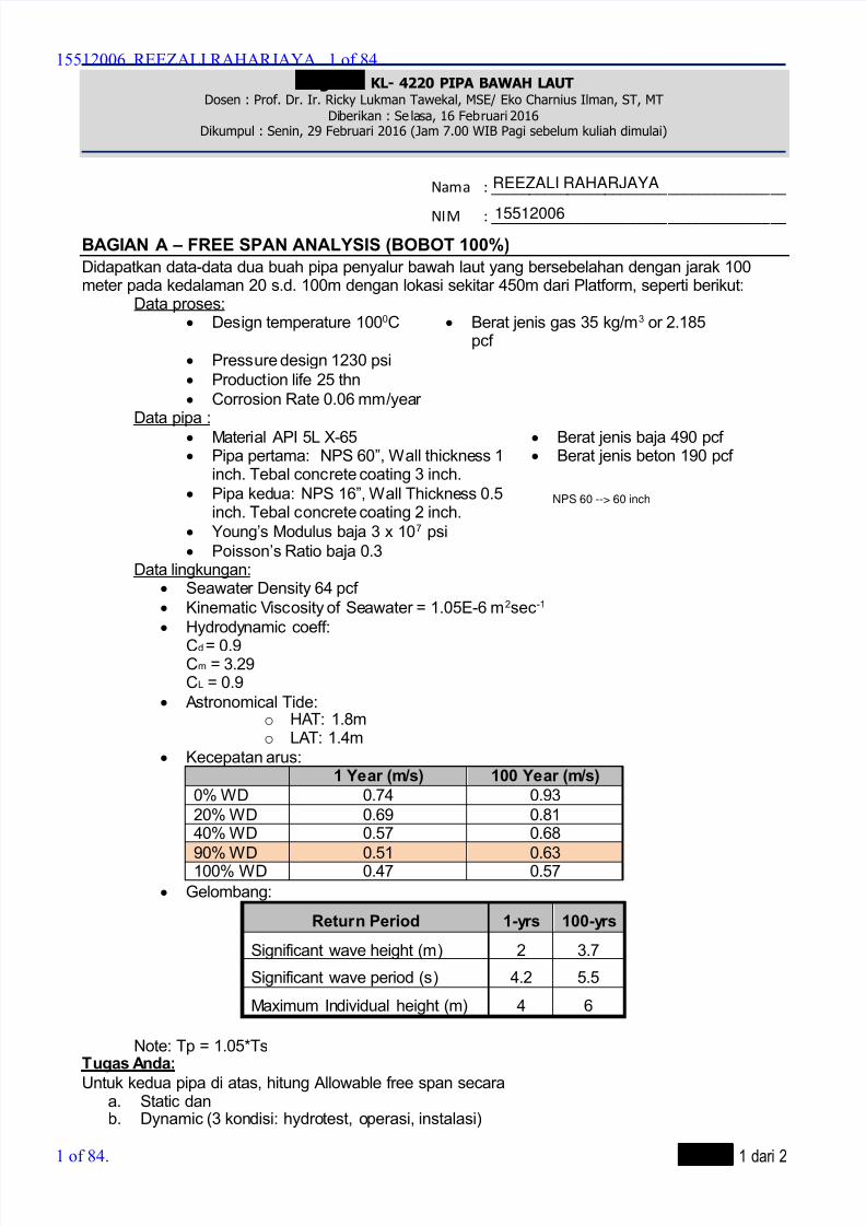
BAGIAN A – FREE SPAN ANALYSIS (BOBOT 100%)
Didapatkan data-data dua buah pipa penyalur bawah laut yang bersebelahan dengan jarak 100meter pada kedalaman 20 s.d. 100m dengan lokasi sekitar 450m dari Platform, seperti berikut:
Data proses: Design temperature 1000C Berat jenis gas 35 kg/m3 or 2.185
pcf
Pressure design 1230 psi Production life 25 thn
Corrosion Rate 0.06 mm/yearData pipa :
Material API 5L X-65 Berat jenis baja 490 pcf Pipa pertama: NPS 60”, Wall thickness 1
inch. Tebal concrete coating 3 inch. Pipa kedua: NPS 16”, Wall Thickness 0.5
inch. Tebal concrete coating 2 inch.
Berat jenis beton 190 pcf
Young’s Modulus baja 3 x 10⁷ psi
Poisson’s Ratio baja 0.3Data lingkungan:
Seawater Density 64 pcf Kinematic Viscosity of Seawater = 1.05E-6 m2sec-1
Hydrodynamic coeff:
Cd = 0.9Cm = 3.29CL = 0.9
Astronomical Tide:o HAT: 1.8mo LAT: 1.4m
Kecepatan arus:1 Year (m/s) 100 Year (m/s)
0% WD 0.74 0.93
20% WD 0.69 0.8140% WD 0.57 0.68
90% WD 0.51 0.63100% WD 0.47 0.57
Gelombang:
Return Period 1-yrs 100-yrs
Significant wave height (m) 2 3.7
Significant wave period (s) 4.2 5.5
Maximum Individual height (m) 4 6
Note: Tp = 1.05*TsTugas Anda:
Untuk kedua pipa di atas, hitung Allowable free span secaraa. Static danb. Dynamic (3 kondisi: hydrotest, operasi, instalasi)
15512006 REEZALI RAHARJAYA 1 of 84.
1 of 84.
NPS 60 --> 60 inch
REEZALI RAHARJAYA
15512006

8/15/2019 HW5 2016 15512006
http://slidepdf.com/reader/full/hw5-2016-15512006 2/84
Halaman 2 dari 2
BAGIAN B – STRESS ANALYSIS AND GLOBAL BUCKLING (BOBOT 100%)
Pipa bawah laut dengan NPS 20 Schedule 40 sepanjang 40 km, dengan material baja API 5L X52memiliki lapisan pelindung anti korosi tipe 3LPP (tebal 3 mm), lapisan pemberat beton dengan tebal1 in. Service berupa gas dengan densitas 80 pcf. Pipa didesain dengan tekanan desain 15 MPa dantemperature desain 100C ini berada di atas seabed dengan kedalaman 30 meter. Dari hasil soil
investigation, diketahui tipe tanah dasar laut adalah pasir dengan sudut gesert tanah 35 dengan
densitas 18835.6 N/m3 dan undrained shear strength 14000 Pa. Kondisi perairan memilikitemperature ambient 25C. Diketahui factor friksi pipa dengan tanah sebesar 0.3. Koefisienekspansi thermal sebesar 1.1710-5 /C. Jarak antara ujung bebas 62 m.
Tugas Anda:
1. (40%) Lakukan analisis upheaval buckling mengikuti metode pada paper AC Palmer OTC
6335. Jika diketahui tinggi imperfection sebesar 1 meter,a. cek apakah diperlukan tambahan gravel dumping untuk mengubur pipa sebagai tambahan
pemberat untuk kestabilan;b. bandingkan regangan yang terjadi terhadap regangan izin berdasarkan kriteria strain based
design.
2. (40%) Untuk pipa yang sama, jika diketahui batimetri dan profil temperature sebagaimanaGambar 1. Lakukan analisis expansi thermal. Kemudian hitunglah besar total ekspansi thermaldan virtual anchor length pada hot-end dan cold-end!
Gambar 1 Profil kedalaman pipa (kiri) dan profil temperatur (kanan) sepanjang pipa
Catatan: Untuk data yang Anda anggap kurang, dapat digunakan asumsi namun ingat untuk mencantumkan sumbernya.
3. (15%) Dengan kata-kata Anda sendiri, berikanlah penjelasan berikut sketsanya mengenai
perilaku global buckling pada suatu potongan pipa dengan kapasitas buckling yang beragamsepanjang pipa, hingga terjadi buckling pertama dan kedua. Anda harus menjelaskanbagaimana prilaku sebelum buckling dan mekanisme yang terjadi saat buckling pertama dankedua. Berikan sketsa yang jelas dan mudah dimengerti untuk setiap penjelasan Anda. Di akhirpenjelasan Anda, tambahkan pula penjelasan apa yang dimaksud dengan dengan globalbuckling sebagai fenomena beban, bukan fenomena kegagalan.
4. (5%) Buatlah sebuah tabel yang memberikan perbedaan antara teori kegagalan : (1) vonmises, (2) tresca, dan (3) rankine. Penjelasan yang komprehensif berbobot lebih.
Catatan:
1. Semua proses perhitungan tahap demi tahap beserta rumus dan keterangan rumus yang dipakai
WAJIB Anda tuliskan! TIDAK BOLEH hanya melampirkan angka-angka tanpa rumus yang dipakai atau
bahkan hanya hasil akhir saja! Pekerjaan Anda harus bisa ditelusuri dengan mudah. Sumber setiap
rumus yang dipakai harus dicantumkan. Misal: “Sumber: Equation 2.3 DnV RP E305 page 20”. Jangan
mencantumkan referensi misalnya:”Slide kuliah balapan atau contoh spreadsheet dst..”. Cek di
standar/codenya langsung.
2. Perhitungan yang Anda lakukan untuk soal ini harus menggunakan EXCEL, Mathcad atau MATLAB.
Tidak boleh menggunakan tulis tangan.--Soal Selesai—
“Perilaku Anti korupsi dimulai sejak dini.. Dilarang mencontek!”
0
50
100
150
0 10 20 30 40 T e m p e r a t u r e ( C )
KP
15512006 REEZALI RAHARJAYA 2 of 84.
2 of 84.
8/15/2019 HW5 2016 15512006
http://slidepdf.com/reader/full/hw5-2016-15512006 3/84
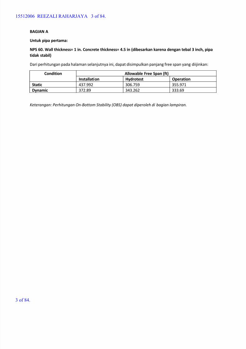
BAGIAN A
Untuk pipa pertama:
NPS 60. Wall thickness= 1 in. Concrete thickness= 4.5 in (dibesarkan karena dengan tebal 3 inch, pipa
tidak stabil)
Dari perhitungan pada halaman selanjutnya ini, dapat disimpulkan panjang free span yang diijinkan:
Condition Allowable Free Span (ft)
Installation Hydrotest Operation
Static 437.992 306.759 355.971
Dynamic 372.89 343.262 333.69
Keterangan: Perhitungan On-Bottom Stability (OBS) dapat diperoleh di bagian lampiran.
15512006 REEZALI RAHARJAYA 3 of 84.
3 of 84.

8/15/2019 HW5 2016 15512006
http://slidepdf.com/reader/full/hw5-2016-15512006 4/84
Free Span Analysis - Hydrotest NPS 60
1. INPUT PARAMETER pcf lb ft
3-:= C K
1.1 Pipeline Design Parameter
Outer Diameter Ds 60in:=
Wall Thickness ts 1in:=
Internal Diameter ID Ds 2ts-:=
Concrete Coang tcc 4.5in:=
Modulus Elascity E 30000ksi:=
Design Pressure Po 1845psi:=
Concrete Coang Density ρcc 190pcf :=
Content Density ρcont 62.4pcf :=
Seawater Density ρsw 64pcf :=
Steel Density ρs 490pcf :=
Design Temperature Td 373K :=
Poisson Rao υ 0.3:=
SMYS API 5L X-65 SMYS 65ksi:=
Corrosion Coang THK tcorr 0in:=
Thermal Coe cient α 1.17 10 5-
1
K :=
Structural Damping δ 0.126:= DNV RP F105 para. 6.2.11
Corrosion Coang Density ρcorr 60pcf :=
Seabed Temperature Tsw 296K :=
1.2 Environmental Parameter
Signi cant Wave Height Hs 2m:=
15512006 REEZALI RAHARJAYA 4 of 84.
4 of 84.

8/15/2019 HW5 2016 15512006
http://slidepdf.com/reader/full/hw5-2016-15512006 5/84
Signi cant Wave Period Ts 4.2s:= T p 1.05 Ts 4.41 s=:=
Water Depth d 100m:=
Current 10% WD Above Seabed Uc 0.51m s 1-:= Zr 10m:=
Kinemac Viscosity of Seawater ν 1.05 10 6-
m2
s 1-
:=
1.3 Soil Parameter
Soil Type 1 = Sand, 2 = Clay soil 2:=
From table A.1 DNV RP
E305Undrained Shear Strength Su 2kPa:= z0 5.21 10
6-m:=
2. CALCULATION
2.1 Submerged Weight Calculation
Outside Diameter Dtot Ds 2tcorr + 2tcc+:= Dtot 1.753m=
Inera I π
64Ds
4ID
4-:= I 0.034m
4=
Elasc Modulus EI E I:= EI 6.946 109
m
3kg
s2
=
Weight of Pipe
Steel Weight Wstπ
4Ds
2ID
2- ρs:= Wst 938.612
kg
m=
Corr. Coat. Weight Wcorr π
4Ds 2tcorr +( )
2Ds
2- ρcorr := Wcorr 0
kg
m=
Concrete Weight Wccπ
4Dtot
2Ds 2tcorr +( )
2- ρcc:= Wcc 1.79 10
3
kg
m=
Content Weight Wcontπ
4ID
2ρcont:= Wcont 1.704 10
3
kg
m=
Added Mass Waddπ
4Dtot
2ρsw:= Wadd 2.473 10
3
kg
m=
Total E ecve Weight Weff Wst Wcorr + Wcont+ Wcc+ Wadd+:= Weff 6.906 103
kg
m=
External Pressure Pe ρsw g d:= Pe 1.005 10
6
Pa=
15512006 REEZALI RAHARJAYA 5 of 84.
5 of 84.
8/15/2019 HW5 2016 15512006
http://slidepdf.com/reader/full/hw5-2016-15512006 6/84
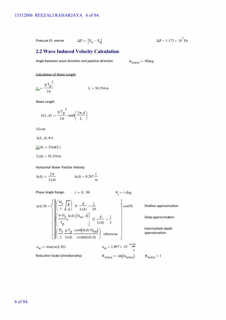
Pressure Di erence ΔP Po Pe-:= ΔP 1.172 107
Pa=
2.2 Wave Induced Velocity Calculation
Angle between wave direcon and pipeline direcon ϕwave 90deg:=
Calculaon of Wave Length
Lg T p
2
2π:= L 30.354 m=
Wave Length
λ L d,( )g T p
2
2π
tanh 2π d
L
:=
Given
λ L d,( ) L=
L d( ) Find L( ):=
L d( ) 30.354m=
Horizontal Water Parcle Velovity
k d( ) 2π
L d( ):= k d( ) 0.207
1
m=
Phase Angle Range: i 0 90..:= θi
i deg:=
u d θ,( )Hs
2
g
d
d
L d( )
1
20<if
π Hs
T p
ek d( ) Dtot d-( )
d
L d( )
1
2
>if
Hs
2
g T p
L d( )
cosh k d( ) Dtot( )cosh k d( ) d( )
otherwise
cos θ( ):= Shallow approximaon
Deep approximaon
Intermediate depth
approximaon
uw max u d θ,( )( ):= uw 2.097 10 9-
m
s=
Reducon factor (direconality) R wave sin ϕwave( ):= R wave 1=
15512006 REEZALI RAHARJAYA 6 of 84.
6 of 84.

8/15/2019 HW5 2016 15512006
http://slidepdf.com/reader/full/hw5-2016-15512006 7/84
Signi cant wave vel. perpendicular
to pipeUw d θ,( ) uw R wave
ln0.5 Ds
z0
lnZr
z0
:=
Horizontal Water Parcle Acceleraon
Uw d θ,( ) 1.724 10 9-
m
s=
Aw d θ,( )Hs π
T p
g
d
d
L d( )
1
20<if
2Hsπ
T p
2
ek d( ) Dtot d-( )
d
L d( )
1
2>if
Hsg π
L d( )
cosh k d( ) Dtot( )cosh k d( ) d( )
otherwise
sin θ( ):=
Aw max Aw d θ,( )( ):= Aw 2.988 10 9- m
s2
=
Signi cant wave acceleraon
perpendicular to pipeAw d θ,( ) Aw R wave:= Aw d θ,( ) 2.988 10
9-
m
s2
=
2.3 Free Span - Dynamic
Stability Number K s
2 Weff δ
ρsw Dtot2
:= K s 0.553=
Formula from DNV 1981 paragraph A.2.1.4
Reduced Velocity Vr 1.62:= From Fig A.3 DNV 1981
Note :
con1 "In-line Oscillation":=
con2 "Cross-flow Oscillation":=
Type of Oscillaon Otype con1 1 Vr < 3.5< K s 1.8<if
con2 otherwise
:=
Otype "In-line Oscillation"=
Strouhal Number St 0.24:= From Fig. A.2 DNV 1981
15512006 REEZALI RAHARJAYA 7 of 84.
7 of 84.
8/15/2019 HW5 2016 15512006
http://slidepdf.com/reader/full/hw5-2016-15512006 8/84
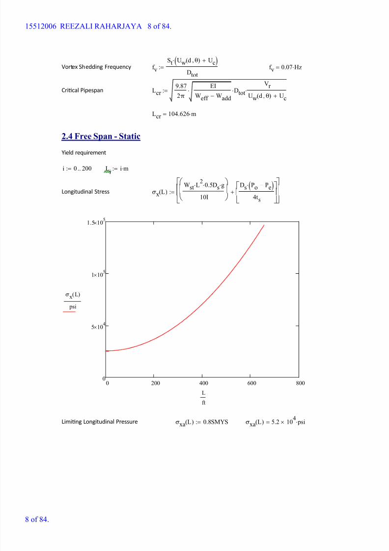
Vortex Shedding Frequency f v
St Uw d θ,( ) Uc+( )
Dtot
:= f v 0.07 Hz=
Crical Pipespan Lcr 9.87
2π
EI
Weff Wadd-
DtotVr
Uw d θ,( ) Uc+
:=
Lcr 104.626 m=
2.4 Free Span - Static
Yield requirement
i 0 200..:= Li
i m:=
Longitudinal Stress σx L( )
Wst L2
0.5 Ds g
10I
Ds Po Pe-( )
4ts
+
:=
0 200 400 600 800
0
5 104
1 105
1.5 105
σx L( )
psi
L
ft
Liming Longitudinal Pressure σxa L( ) 0.8SMYS:= σxa L( ) 5.2 104
psi=
15512006 REEZALI RAHARJAYA 8 of 84.
8 of 84.
8/15/2019 HW5 2016 15512006
http://slidepdf.com/reader/full/hw5-2016-15512006 9/84
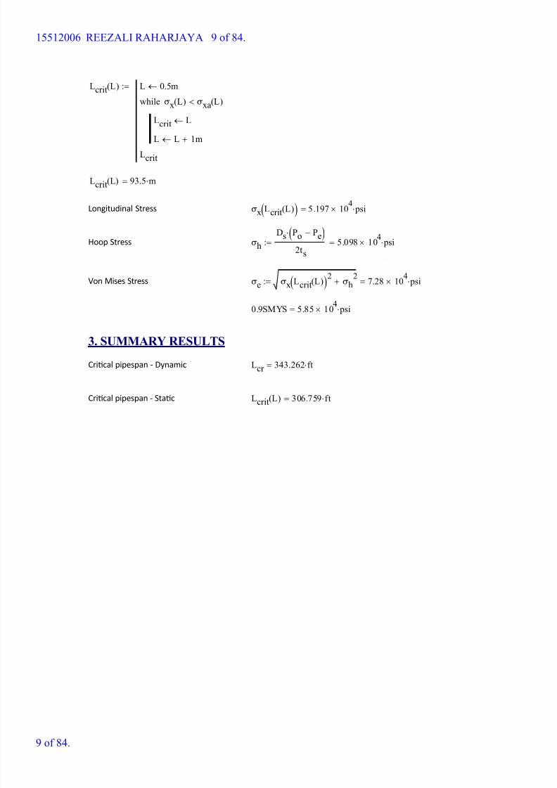
Lcrit L( ) L 0.5m
Lcrit L
L L 1m+
σx L( ) σxa L( )<while
Lcrit
:=
Lcrit L( ) 93.5 m=
Longitudinal Stress σx Lcrit L( )( ) 5.197 104
psi=
Hoop Stress σh
Ds Po Pe-( )
2ts
5.098 104
psi=:=
Von Mises Stress σe σx Lcrit L( )( )2 σh2+ 7.28 104 psi=:=
0.9SMYS 5.85 104
psi=
3. SUMMARY RESULTS
Crical pipespan - Dynamic Lcr 343.262 ft=
Crical pipespan - Stac Lcrit L( ) 306.759 ft=
15512006 REEZALI RAHARJAYA 9 of 84.
9 of 84.
8/15/2019 HW5 2016 15512006
http://slidepdf.com/reader/full/hw5-2016-15512006 10/84
Free Span Analysis - Instalasi NPS 60
1. INPUT PARAMETER pcf lb ft
3-:= C K
1.1 Pipeline Design Parameter
Outer Diameter Ds 60in:=
Wall Thickness ts 1in:=
Internal Diameter ID Ds 2ts-:=
Concrete Coang tcc 4.5in:=
Modulus Elascity E 30000ksi:=
Design Pressure Po 0psi:=
Concrete Coang Density ρcc 190pcf :=
Content Density ρcont 0pcf :=
Seawater Density ρsw 64pcf :=
Steel Density ρs 490pcf :=
Design Temperature Td 373K :=
Poisson Rao υ 0.3:=
SMYS API 5L X-65 SMYS 65ksi:=
Corrosion Coang THK tcorr 0in:=
Thermal Coe cient α 1.17 10 5-
1
K :=
Structural Damping δ 0.126:= DNV RP F105 para. 6.2.11
Corrosion Coang Density ρcorr 60pcf :=
Seabed Temperature Tsw 296K :=
1.2 Environmental Parameter
Signi cant Wave Height Hs 2m:=
15512006 REEZALI RAHARJAYA 10 of 84.
10 of 84.
8/15/2019 HW5 2016 15512006
http://slidepdf.com/reader/full/hw5-2016-15512006 11/84

8/15/2019 HW5 2016 15512006
http://slidepdf.com/reader/full/hw5-2016-15512006 12/84
Pressure Di erence ΔP Po Pe-:= ΔP 1.005 106
Pa=
2.2 Wave Induced Velocity Calculation
Angle between wave direcon and pipeline direcon ϕwave 90deg:=
Calculaon of Wave Length
Lg T p
2
2π:= L 30.354 m=
Wave Length
λ L d,( )g T p
2
2π
tanh 2π d
L
:=
Given
λ L d,( ) L=
L d( ) Find L( ):=
L d( ) 30.354m=
Horizontal Water Parcle Velovity
k d( ) 2π
L d( ):= k d( ) 0.207
1
m=
Phase Angle Range: i 0 90..:= θi
i deg:=
u d θ,( )Hs
2
g
d
d
L d( )
1
20<if
π Hs
T p
ek d( ) Dtot d-( )
d
L d( )
1
2
>if
Hs
2
g T p
L d( )
cosh k d( ) Dtot( )cosh k d( ) d( )
otherwise
cos θ( ):= Shallow approximaon
Deep approximaon
Intermediate depth
approximaon
uw max u d θ,( )( ):= uw 2.097 10 9-
m
s=
Reducon factor (direconality) R wave sin ϕwave( ):= R wave 1=
15512006 REEZALI RAHARJAYA 12 of 84.
12 of 84.

8/15/2019 HW5 2016 15512006
http://slidepdf.com/reader/full/hw5-2016-15512006 13/84
Signi cant wave vel. perpendicular
to pipeUw d θ,( ) uw R wave
ln0.5 Ds
z0
lnZr
z0
:=
Horizontal Water Parcle Acceleraon
Uw d θ,( ) 1.724 10 9-
m
s=
Aw d θ,( )Hs π
T p
g
d
d
L d( )
1
20<if
2Hsπ
T p
2
ek d( ) Dtot d-( )
d
L d( )
1
2>if
Hsg π
L d( )
cosh k d( ) Dtot( )cosh k d( ) d( )
otherwise
sin θ( ):=
Aw max Aw d θ,( )( ):= Aw 2.988 10 9- m
s2
=
Signi cant wave acceleraon
perpendicular to pipeAw d θ,( ) Aw R wave:= Aw d θ,( ) 2.988 10
9-
m
s2
=
2.3 Free Span - Dynamic
Stability Number K s
2 Weff δ
ρsw Dtot2
:= K s 0.416=
Formula from DNV 1981 paragraph A.2.1.4
Reduced Velocity Vr 1.5:= From Fig A.3 DNV 1981
Note :
con1 "In-line Oscillation":=
con2 "Cross-flow Oscillation":=
Type of Oscillaon Otype con1 1 Vr < 3.5< K s 1.8<if
con2 otherwise
:=
Otype "In-line Oscillation"=
Strouhal Number St 0.24:= From Fig. A.2 DNV 1981
15512006 REEZALI RAHARJAYA 13 of 84.
13 of 84.
8/15/2019 HW5 2016 15512006
http://slidepdf.com/reader/full/hw5-2016-15512006 14/84
Vortex Shedding Frequency f v
St Uw d θ,( ) Uc+( )
Dtot
:= f v 0.07 Hz=
Crical Pipespan Lcr 9.87
2π
EI
Weff Wadd-
DtotVr
Uw d θ,( ) Uc+
:=
Lcr 113.657 m=
2.4 Free Span - Static
Yield requirement
i 0 200..:= Li
i m:=
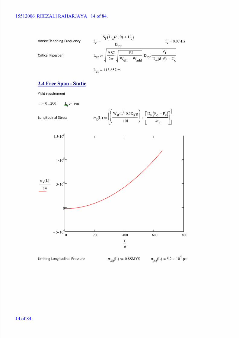
Longitudinal Stress σx L( )
Wst L2
0.5 Ds g
10I
Ds Po Pe-( )
4ts
+
:=
0 200 400 600 800
5- 104
0
5 104
1 105
1.5 105
σx L( )
psi
L
ft
Liming Longitudinal Pressure σxa L( ) 0.8SMYS:= σxa L( ) 5.2 104
psi=
15512006 REEZALI RAHARJAYA 14 of 84.
14 of 84.

8/15/2019 HW5 2016 15512006
http://slidepdf.com/reader/full/hw5-2016-15512006 15/84
Lcrit L( ) L 0.5m
Lcrit L
L L 1m+
σx L( ) σxa L( )<while
Lcrit
:=
Lcrit L( ) 133.5 m=
Longitudinal Stress σx Lcrit L( )( ) 5.18 104
psi=
Hoop Stress σh
Ds Po Pe-( )
2ts
4.374- 103
psi=:=
Von Mises Stress σe σx Lcrit L( )( )2 σh2+ 5.199 104 psi=:=
0.9SMYS 5.85 104
psi=
3. SUMMARY RESULTS
Crical pipespan - Dynamic Lcr 372.89 ft=
Crical pipespan - Stac Lcrit L( ) 437.992 ft=
15512006 REEZALI RAHARJAYA 15 of 84.
15 of 84.

8/15/2019 HW5 2016 15512006
http://slidepdf.com/reader/full/hw5-2016-15512006 16/84
Free Span Analysis - Operaon NPS 60
1. INPUT PARAMETER pcf lb ft
3-:= C K
1.1 Pipeline Design Parameter
Outer Diameter Ds 60in:=
Wall Thickness ts 1in:=
Internal Diameter ID Ds 2ts-:=
Concrete Coang tcc 4.5in:=
Modulus Elascity E 30000ksi:=
Design Pressure Po 1230psi:=
Concrete Coang Density ρcc 190pcf :=
Content Density ρcont 2.185pcf :=
Seawater Density ρsw 64pcf :=
Steel Density ρs 490pcf :=
Design Temperature Td 373K :=
Poisson Rao υ 0.3:=
SMYS API 5L X-65 SMYS 65ksi:=
Corrosion Coang THK tcorr 0in:=
Thermal Coe cient α 1.17 10 5-
1
K :=
Structural Damping δ 0.126:= DNV RP F105 para. 6.2.11
Corrosion Coang Density ρcorr 60pcf :=
Seabed Temperature Tsw 296K :=
1.2 Environmental Parameter
Signi cant Wave Height Hs 3.7m:=
15512006 REEZALI RAHARJAYA 16 of 84.
16 of 84.
8/15/2019 HW5 2016 15512006
http://slidepdf.com/reader/full/hw5-2016-15512006 17/84
Signi cant Wave Period Ts 5.5s:= T p 1.05 Ts 5.775s=:=
Water Depth d 100m:=
Current 10% WD Above Seabed Uc 0.63m s 1-:= Zr 10m:=
Kinemac Viscosity of Seawater ν 1.05 10 6-
m2
s 1-
:=
1.3 Soil Parameter
Soil Type 1 = Sand, 2 = Clay soil 2:=
From table A.1 DNV RP
E305Undrained Shear Strength Su 2kPa:= z0 5.21 10
6-m:=
2. CALCULATION
2.1 Submerged Weight Calculation
Outside Diameter Dtot Ds 2tcorr + 2tcc+:= Dtot 1.753m=
Inera I π
64Ds
4ID
4-:= I 0.034m
4=
Elasc Modulus EI E I:= EI 6.946 109
m
3kg
s2
=
Weight of Pipe
Steel Weight Wstπ
4Ds
2ID
2- ρs:= Wst 938.612
kg
m=
Corr. Coat. Weight Wcorr π
4Ds 2tcorr +( )
2Ds
2- ρcorr := Wcorr 0
kg
m=
Concrete Weight Wccπ
4Dtot
2Ds 2tcorr +( )
2- ρcc:= Wcc 1.79 10
3
kg
m=
Content Weight Wcontπ
4ID
2ρcont:= Wcont 59.66
kg
m=
Added Mass Waddπ
4Dtot
2ρsw:= Wadd 2.473 10
3
kg
m=
Total E ecve Weight Weff Wst Wcorr + Wcont+ Wcc+ Wadd+:= Weff 5.262 103
kg
m=
External Pressure Pe ρsw g d:= Pe 1.005 10
6
Pa=
15512006 REEZALI RAHARJAYA 17 of 84.
17 of 84.

8/15/2019 HW5 2016 15512006
http://slidepdf.com/reader/full/hw5-2016-15512006 18/84
Pressure Di erence ΔP Po Pe-:= ΔP 7.475 106
Pa=
2.2 Wave Induced Velocity Calculation
Angle between wave direcon and pipeline direcon ϕwave 90deg:=
Calculaon of Wave Length
Lg T p
2
2π:= L 52.053 m=
Wave Length
λ L d,( )g T p
2
2π
tanh 2π d
L
:=
Given
λ L d,( ) L=
L d( ) Find L( ):=
L d( ) 52.053m=
Horizontal Water Parcle Velovity
k d( ) 2π
L d( ):= k d( ) 0.121
1
m=
Phase Angle Range: i 0 90..:= θi
i deg:=
u d θ,( )Hs
2
g
d
d
L d( )
1
20<if
π Hs
T p
ek d( ) Dtot d-( )
d
L d( )
1
2
>if
Hs
2
g T p
L d( )
cosh k d( ) Dtot( )cosh k d( ) d( )
otherwise
cos θ( ):= Shallow approximaon
Deep approximaon
Intermediate depth
approximaon
uw max u d θ,( )( ):= uw 1.424 10 5-
m
s=
Reducon factor (direconality) R wave sin ϕwave( ):= R wave 1=
15512006 REEZALI RAHARJAYA 18 of 84.
18 of 84.
8/15/2019 HW5 2016 15512006
http://slidepdf.com/reader/full/hw5-2016-15512006 19/84
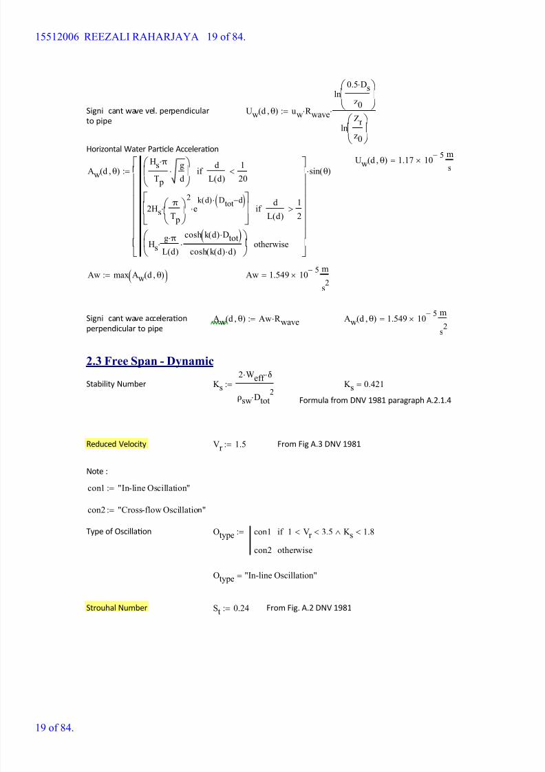
Signi cant wave vel. perpendicular
to pipeUw d θ,( ) uw R wave
ln0.5 Ds
z0
lnZr
z0
:=
Horizontal Water Parcle Acceleraon
Uw d θ,( ) 1.17 10 5-
m
s=
Aw d θ,( )Hs π
T p
g
d
d
L d( )
1
20<if
2Hsπ
T p
2
ek d( ) Dtot d-( )
d
L d( )
1
2>if
Hsg π
L d( )
cosh k d( ) Dtot( )cosh k d( ) d( )
otherwise
sin θ( ):=
Aw max Aw d θ,( )( ):= Aw 1.549 10 5- m
s2
=
Signi cant wave acceleraon
perpendicular to pipeAw d θ,( ) Aw R wave:= Aw d θ,( ) 1.549 10
5-
m
s2
=
2.3 Free Span - Dynamic
Stability Number K s
2 Weff δ
ρsw Dtot2
:= K s 0.421=
Formula from DNV 1981 paragraph A.2.1.4
Reduced Velocity Vr 1.5:= From Fig A.3 DNV 1981
Note :
con1 "In-line Oscillation":=
con2 "Cross-flow Oscillation":=
Type of Oscillaon Otype con1 1 Vr < 3.5< K s 1.8<if
con2 otherwise
:=
Otype "In-line Oscillation"=
Strouhal Number St 0.24:= From Fig. A.2 DNV 1981
15512006 REEZALI RAHARJAYA 19 of 84.
19 of 84.
8/15/2019 HW5 2016 15512006
http://slidepdf.com/reader/full/hw5-2016-15512006 20/84
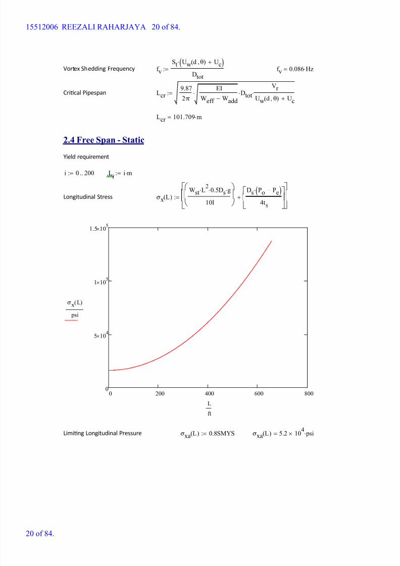
Vortex Shedding Frequency f v
St Uw d θ,( ) Uc+( )
Dtot
:= f v 0.086 Hz=
Crical Pipespan Lcr 9.87
2π
EI
Weff Wadd-
DtotVr
Uw d θ,( ) Uc+
:=
Lcr 101.709 m=
2.4 Free Span - Static
Yield requirement
i 0 200..:= Li
i m:=
Longitudinal Stress σx L( )
Wst L2
0.5 Ds g
10I
Ds Po Pe-( )
4ts
+
:=
0 200 400 600 800
0
5 104
1 105
1.5 105
σx L( )
psi
L
ft
Liming Longitudinal Pressure σxa L( ) 0.8SMYS:= σxa L( ) 5.2 104
psi=
15512006 REEZALI RAHARJAYA 20 of 84.
20 of 84.

8/15/2019 HW5 2016 15512006
http://slidepdf.com/reader/full/hw5-2016-15512006 21/84
Lcrit L( ) L 0.5m
Lcrit L
L L 1m+
σx L( ) σxa L( )<while
Lcrit
:=
Lcrit L( ) 108.5 m=
Longitudinal Stress σx Lcrit L( )( ) 5.193 104
psi=
Hoop Stress σh
Ds Po Pe-( )
2ts
3.253 104
psi=:=
Von Mises Stress σe σx Lcrit L( )( )2 σh2+ 6.127 104 psi=:=
0.9SMYS 5.85 104
psi=
3. SUMMARY RESULTS
Crical pipespan - Dynamic Lcr 333.69 ft=
Crical pipespan - Stac Lcrit L( ) 355.971 ft=
15512006 REEZALI RAHARJAYA 21 of 84.
21 of 84.
8/15/2019 HW5 2016 15512006
http://slidepdf.com/reader/full/hw5-2016-15512006 22/84
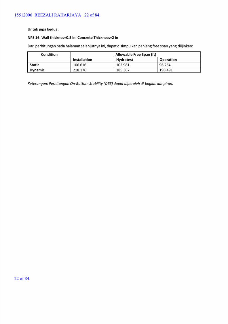
Untuk pipa kedua:
NPS 16. Wall thicknes=0.5 in. Concrete Thickness=2 in
Dari perhitungan pada halaman selanjutnya ini, dapat disimpulkan panjang free span yang diijinkan:
Condition Allowable Free Span (ft)
Installation Hydrotest Operation
Static 106.616 102.981 96.254
Dynamic 218.176 185.367 198.491
Keterangan: Perhitungan On-Bottom Stability (OBS) dapat diperoleh di bagian lampiran.
15512006 REEZALI RAHARJAYA 22 of 84.
22 of 84.

8/15/2019 HW5 2016 15512006
http://slidepdf.com/reader/full/hw5-2016-15512006 23/84
Free Span Analysis - Hydrotest NPS 16
1. INPUT PARAMETER pcf lb ft
3-:= C K
1.1 Pipeline Design Parameter
Outer Diameter Ds 16in:=
Wall Thickness ts 0.5in:=
Internal Diameter ID Ds 2ts-:=
Concrete Coang tcc 2in:=
Modulus Elascity E 30000ksi:=
Design Pressure Po 1845psi:=
Concrete Coang Density ρcc 190pcf :=
Content Density ρcont 62.4pcf :=
Seawater Density ρsw 64pcf :=
Steel Density ρs 490pcf :=
Design Temperature Td 373K :=
Poisson Rao υ 0.3:=
SMYS API 5L X-65 SMYS 65ksi:=
Corrosion Coang THK tcorr 0in:=
Thermal Coe cient α 1.17 10 5-
1
K :=
Structural Damping δ 0.126:= DNV RP F105 para. 6.2.11
Corrosion Coang Density ρcorr 60pcf :=
Seabed Temperature Tsw 296K :=
1.2 Environmental Parameter
Signi cant Wave Height Hs 2m:=
15512006 REEZALI RAHARJAYA 23 of 84.
23 of 84.

8/15/2019 HW5 2016 15512006
http://slidepdf.com/reader/full/hw5-2016-15512006 24/84
Signi cant Wave Period Ts 4.2s:= T p 1.05 Ts 4.41 s=:=
Water Depth d 100m:=
Current 10% WD Above Seabed Uc 0.51m s 1-:= Zr 10m:=
Kinemac Viscosity of Seawater ν 1.05 10 6-
m2
s 1-
:=
1.3 Soil Parameter
Soil Type 1 = Sand, 2 = Clay soil 2:=
From table A.1 DNV RP
E305Undrained Shear Strength Su 2kPa:= z0 5.21 10
6-m:=
2. CALCULATION
2.1 Submerged Weight Calculation
Outside Diameter Dtot Ds 2tcorr + 2tcc+:= Dtot 0.508m=
Inera I π
64Ds
4ID
4-:= I 3.047 10
4- m
4=
Elasc Modulus EI E I:= EI 6.302 107
kg m
3
s2
=
Weight of Pipe
Steel Weight Wstπ
4Ds
2ID
2- ρs:= Wst 123.292
kg
m=
Corr. Coat. Weight Wcorr π
4Ds 2tcorr +( )
2Ds
2- ρcorr := Wcorr 0
kg
m=
Concrete Weight Wccπ
4Dtot
2Ds 2tcorr +( )
2- ρcc:= Wcc 222.072
kg
m=
Content Weight Wcontπ
4ID
2ρcont:= Wcont 113.958
kg
m=
Added Mass Waddπ
4Dtot
2ρsw:= Wadd 207.787
kg
m=
Total E ecve Weight Weff Wst Wcorr + Wcont+ Wcc+ Wadd+:= Weff 667.11 kg
m=
External Pressure Pe ρsw g d:= Pe 1.005 10
6
Pa=
15512006 REEZALI RAHARJAYA 24 of 84.
24 of 84.
8/15/2019 HW5 2016 15512006
http://slidepdf.com/reader/full/hw5-2016-15512006 25/84
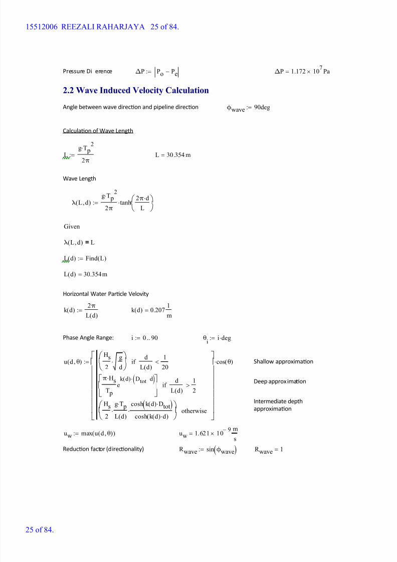
Pressure Di erence ΔP Po Pe-:= ΔP 1.172 107
Pa=
2.2 Wave Induced Velocity Calculation
Angle between wave direcon and pipeline direcon ϕwave 90deg:=
Calculaon of Wave Length
Lg T p
2
2π:= L 30.354 m=
Wave Length
λ L d,( )g T p
2
2π
tanh 2π d
L
:=
Given
λ L d,( ) L=
L d( ) Find L( ):=
L d( ) 30.354m=
Horizontal Water Parcle Velovity
k d( ) 2π
L d( ):= k d( ) 0.207
1
m=
Phase Angle Range: i 0 90..:= θi
i deg:=
u d θ,( )Hs
2
g
d
d
L d( )
1
20<if
π Hs
T p
ek d( ) Dtot d-( )
d
L d( )
1
2
>if
Hs
2
g T p
L d( )
cosh k d( ) Dtot( )cosh k d( ) d( )
otherwise
cos θ( ):= Shallow approximaon
Deep approximaon
Intermediate depth
approximaon
uw max u d θ,( )( ):= uw 1.621 10 9-
m
s=
Reducon factor (direconality) R wave sin ϕwave( ):= R wave 1=
15512006 REEZALI RAHARJAYA 25 of 84.
25 of 84.

8/15/2019 HW5 2016 15512006
http://slidepdf.com/reader/full/hw5-2016-15512006 26/84
Signi cant wave vel. perpendicular
to pipeUw d θ,( ) uw R wave
ln0.5 Ds
z0
lnZr
z0
:=
Horizontal Water Parcle Acceleraon
Uw d θ,( ) 1.184 10 9-
m
s=
Aw d θ,( )Hs π
T p
g
d
d
L d( )
1
20<if
2Hsπ
T p
2
ek d( ) Dtot d-( )
d
L d( )
1
2>if
Hsg π
L d( )
cosh k d( ) Dtot( )cosh k d( ) d( )
otherwise
sin θ( ):=
Aw max Aw d θ,( )( ):= Aw 2.309 10 9- m
s2
=
Signi cant wave acceleraon
perpendicular to pipeAw d θ,( ) Aw R wave:= Aw d θ,( ) 2.309 10
9-
m
s2
=
2.3 Free Span - Dynamic
Stability Number K s
2 Weff δ
ρsw Dtot2
:= K s 0.635=
Formula from DNV 1981 paragraph A.2.1.4
Reduced Velocity Vr 1.7:= From Fig A.3 DNV 1981
Note :
con1 "In-line Oscillation":=
con2 "Cross-flow Oscillation":=
Type of Oscillaon Otype con1 1 Vr < 3.5< K s 1.8<if
con2 otherwise
:=
Otype "In-line Oscillation"=
Strouhal Number St 0.24:= From Fig. A.2 DNV 1981
15512006 REEZALI RAHARJAYA 26 of 84.
26 of 84.

8/15/2019 HW5 2016 15512006
http://slidepdf.com/reader/full/hw5-2016-15512006 27/84
Vortex Shedding Frequency f v
St Uw d θ,( ) Uc+( )
Dtot
:= f v 0.241 Hz=
Crical Pipespan Lcr 9.87
2π
EI
Weff Wadd-
DtotVr
Uw d θ,( ) Uc+
:=
Lcr 31.389 m=
2.4 Free Span - Static
Yield requirement
i 0 200..:= Li
i m:=
Longitudinal Stress σx L( )
Wst L2
0.5 Ds g
10I
Ds Po Pe-( )
4ts
+
:=
0 200 400 600 800
0
1 105
2 105
3 105
4 105
5 105
σx L( )
psi
L
ft
Liming Longitudinal Pressure σxa L( ) 0.8SMYS:= σxa L( ) 5.2 104
psi=
15512006 REEZALI RAHARJAYA 27 of 84.
27 of 84.

8/15/2019 HW5 2016 15512006
http://slidepdf.com/reader/full/hw5-2016-15512006 28/84
Lcrit L( ) L 0.5m
Lcrit L
L L 1m+
σx L( ) σxa L( )<while
Lcrit
:=
Lcrit L( ) 56.5 m=
Longitudinal Stress σx Lcrit L( )( ) 5.093 104
psi=
Hoop Stress σh
Ds Po Pe-( )
2ts
2.719 104
psi=:=
Von Mises Stress σe σx Lcrit L( )( )2 σh2+ 5.773 104 psi=:=
0.9SMYS 5.85 104
psi=
3. SUMMARY RESULTS
Crical pipespan - Dynamic Lcr 102.981 ft=
Crical pipespan - Stac Lcrit L( ) 185.367 ft=
15512006 REEZALI RAHARJAYA 28 of 84.
28 of 84.

8/15/2019 HW5 2016 15512006
http://slidepdf.com/reader/full/hw5-2016-15512006 29/84
Free Span Analysis - Instalasi NPS 16
1. INPUT PARAMETER pcf lb ft
3-:= C K
1.1 Pipeline Design Parameter
Outer Diameter Ds 16in:=
Wall Thickness ts 0.5in:=
Internal Diameter ID Ds 2ts-:=
Concrete Coang tcc 2in:=
Modulus Elascity E 30000ksi:=
Design Pressure Po 0psi:=
Concrete Coang Density ρcc 190pcf :=
Content Density ρcont 0pcf :=
Seawater Density ρsw 64pcf :=
Steel Density ρs 490pcf :=
Design Temperature Td 373K :=
Poisson Rao υ 0.3:=
SMYS API 5L X-65 SMYS 65ksi:=
Corrosion Coang THK tcorr 0in:=
Thermal Coe cient α 1.17 10 5-
1
K :=
Structural Damping δ 0.126:= DNV RP F105 para. 6.2.11
Corrosion Coang Density ρcorr 60pcf :=
Seabed Temperature Tsw 296K :=
1.2 Environmental Parameter
Signi cant Wave Height Hs 2m:=
15512006 REEZALI RAHARJAYA 29 of 84.
29 of 84.
8/15/2019 HW5 2016 15512006
http://slidepdf.com/reader/full/hw5-2016-15512006 30/84
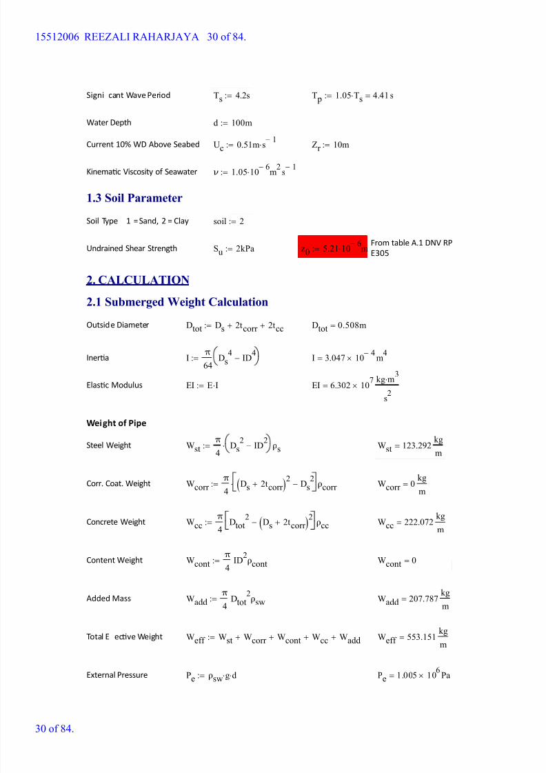
Signi cant Wave Period Ts 4.2s:= T p 1.05 Ts 4.41 s=:=
Water Depth d 100m:=
Current 10% WD Above Seabed Uc 0.51m s 1-:= Zr 10m:=
Kinemac Viscosity of Seawater ν 1.05 10 6-
m2
s 1-
:=
1.3 Soil Parameter
Soil Type 1 = Sand, 2 = Clay soil 2:=
From table A.1 DNV RP
E305Undrained Shear Strength Su 2kPa:= z0 5.21 10
6-m:=
2. CALCULATION
2.1 Submerged Weight Calculation
Outside Diameter Dtot Ds 2tcorr + 2tcc+:= Dtot 0.508m=
Inera I π
64Ds
4ID
4-:= I 3.047 10
4- m
4=
Elasc Modulus EI E I:= EI 6.302 107
kg m
3
s2
=
Weight of Pipe
Steel Weight Wstπ
4Ds
2ID
2- ρs:= Wst 123.292
kg
m=
Corr. Coat. Weight Wcorr π
4Ds 2tcorr +( )
2Ds
2- ρcorr := Wcorr 0
kg
m=
Concrete Weight Wccπ
4Dtot
2Ds 2tcorr +( )
2- ρcc:= Wcc 222.072
kg
m=
Content Weight Wcontπ
4ID
2ρcont:= Wcont 0=
Added Mass Waddπ
4Dtot
2ρsw:= Wadd 207.787
kg
m=
Total E ecve Weight Weff Wst Wcorr + Wcont+ Wcc+ Wadd+:= Weff 553.151 kg
m=
External Pressure Pe ρsw g d:= Pe 1.005 10
6
Pa=
15512006 REEZALI RAHARJAYA 30 of 84.
30 of 84.

8/15/2019 HW5 2016 15512006
http://slidepdf.com/reader/full/hw5-2016-15512006 31/84
Pressure Di erence ΔP Po Pe-:= ΔP 1.005 106
Pa=
2.2 Wave Induced Velocity Calculation
Angle between wave direcon and pipeline direcon ϕwave 90deg:=
Calculaon of Wave Length
Lg T p
2
2π:= L 30.354 m=
Wave Length
λ L d,( )g T p
2
2π
tanh 2π d
L
:=
Given
λ L d,( ) L=
L d( ) Find L( ):=
L d( ) 30.354m=
Horizontal Water Parcle Velovity
k d( ) 2π
L d( ):= k d( ) 0.207
1
m=
Phase Angle Range: i 0 90..:= θi
i deg:=
u d θ,( )Hs
2
g
d
d
L d( )
1
20<if
π Hs
T p
ek d( ) Dtot d-( )
d
L d( )
1
2
>if
Hs
2
g T p
L d( )
cosh k d( ) Dtot( )cosh k d( ) d( )
otherwise
cos θ( ):= Shallow approximaon
Deep approximaon
Intermediate depth
approximaon
uw max u d θ,( )( ):= uw 1.621 10 9-
m
s=
Reducon factor (direconality) R wave sin ϕwave( ):= R wave 1=
15512006 REEZALI RAHARJAYA 31 of 84.
31 of 84.

8/15/2019 HW5 2016 15512006
http://slidepdf.com/reader/full/hw5-2016-15512006 32/84
Signi cant wave vel. perpendicular
to pipeUw d θ,( ) uw R wave
ln0.5 Ds
z0
lnZr
z0
:=
Horizontal Water Parcle Acceleraon
Uw d θ,( ) 1.184 10 9-
m
s=
Aw d θ,( )Hs π
T p
g
d
d
L d( )
1
20<if
2Hsπ
T p
2
ek d( ) Dtot d-( )
d
L d( )
1
2>if
Hsg π
L d( )
cosh k d( ) Dtot( )cosh k d( ) d( )
otherwise
sin θ( ):=
Aw max Aw d θ,( )( ):= Aw 2.309 10 9- m
s2
=
Signi cant wave acceleraon
perpendicular to pipeAw d θ,( ) Aw R wave:= Aw d θ,( ) 2.309 10
9-
m
s2
=
2.3 Free Span - Dynamic
Stability Number K s
2 Weff δ
ρsw Dtot2
:= K s 0.527=
Formula from DNV 1981 paragraph A.2.1.4
Reduced Velocity Vr 1.58:= From Fig A.3 DNV 1981
Note :
con1 "In-line Oscillation":=
con2 "Cross-flow Oscillation":=
Type of Oscillaon Otype con1 1 Vr < 3.5< K s 1.8<if
con2 otherwise
:=
Otype "In-line Oscillation"=
Strouhal Number St 0.24:= From Fig. A.2 DNV 1981
15512006 REEZALI RAHARJAYA 32 of 84.
32 of 84.
8/15/2019 HW5 2016 15512006
http://slidepdf.com/reader/full/hw5-2016-15512006 33/84

8/15/2019 HW5 2016 15512006
http://slidepdf.com/reader/full/hw5-2016-15512006 34/84
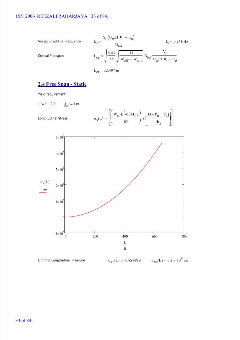
Lcrit L( ) L 0.5m
Lcrit L
L L 1m+
σx L( ) σxa L( )<while
Lcrit
:=
Lcrit L( ) 66.5 m=
Longitudinal Stress σx Lcrit L( )( ) 5.056 104
psi=
Hoop Stress σh
Ds Po Pe-( )
2ts
2.333- 103
psi=:=
Von Mises Stress σe σx Lcrit L( )( )2 σh2+ 5.061 104 psi=:=
0.9SMYS 5.85 104
psi=
3. SUMMARY RESULTS
Crical pipespan - Dynamic Lcr 106.616 ft=
Crical pipespan - Stac Lcrit L( ) 218.176 ft=
15512006 REEZALI RAHARJAYA 34 of 84.
34 of 84.
8/15/2019 HW5 2016 15512006
http://slidepdf.com/reader/full/hw5-2016-15512006 35/84
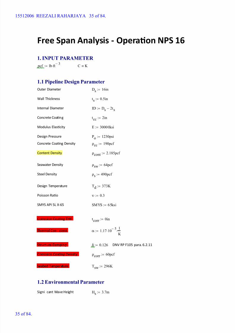
Free Span Analysis - Operaon NPS 16
1. INPUT PARAMETER pcf lb ft
3-:= C K
1.1 Pipeline Design Parameter
Outer Diameter Ds 16in:=
Wall Thickness ts 0.5in:=
Internal Diameter ID Ds 2ts-:=
Concrete Coang tcc 2in:=
Modulus Elascity E 30000ksi:=
Design Pressure Po 1230psi:=
Concrete Coang Density ρcc 190pcf :=
Content Density ρcont 2.185pcf :=
Seawater Density ρsw 64pcf :=
Steel Density ρs 490pcf :=
Design Temperature Td 373K :=
Poisson Rao υ 0.3:=
SMYS API 5L X-65 SMYS 65ksi:=
Corrosion Coang THK tcorr 0in:=
Thermal Coe cient α 1.17 10 5-
1
K :=
Structural Damping δ 0.126:= DNV RP F105 para. 6.2.11
Corrosion Coang Density ρcorr 60pcf :=
Seabed Temperature Tsw 296K :=
1.2 Environmental Parameter
Signi cant Wave Height Hs 3.7m:=
15512006 REEZALI RAHARJAYA 35 of 84.
35 of 84.
8/15/2019 HW5 2016 15512006
http://slidepdf.com/reader/full/hw5-2016-15512006 36/84
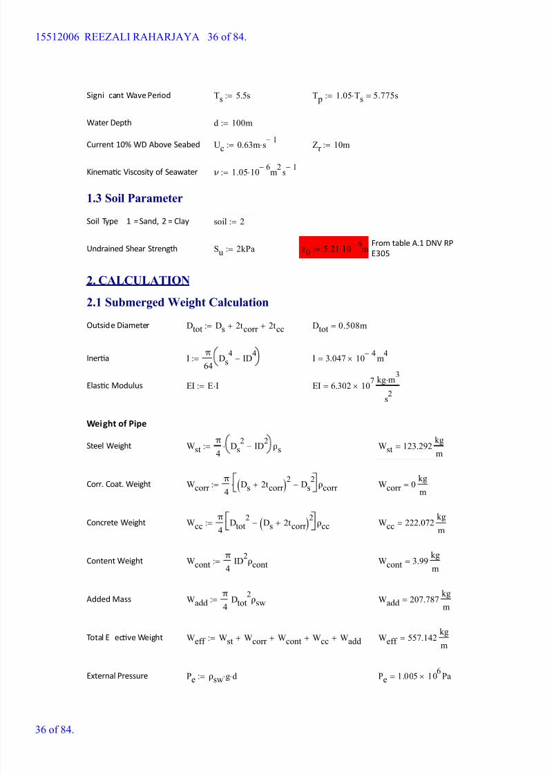
Signi cant Wave Period Ts 5.5s:= T p 1.05 Ts 5.775s=:=
Water Depth d 100m:=
Current 10% WD Above Seabed Uc 0.63m s 1-:= Zr 10m:=
Kinemac Viscosity of Seawater ν 1.05 10 6-
m2
s 1-
:=
1.3 Soil Parameter
Soil Type 1 = Sand, 2 = Clay soil 2:=
From table A.1 DNV RP
E305Undrained Shear Strength Su 2kPa:= z0 5.21 10
6-m:=
2. CALCULATION
2.1 Submerged Weight Calculation
Outside Diameter Dtot Ds 2tcorr + 2tcc+:= Dtot 0.508m=
Inera I π
64Ds
4ID
4-:= I 3.047 10
4- m
4=
Elasc Modulus EI E I:= EI 6.302 107
kg m
3
s2
=
Weight of Pipe
Steel Weight Wstπ
4Ds
2ID
2- ρs:= Wst 123.292
kg
m=
Corr. Coat. Weight Wcorr π
4Ds 2tcorr +( )
2Ds
2- ρcorr := Wcorr 0
kg
m=
Concrete Weight Wccπ
4Dtot
2Ds 2tcorr +( )
2- ρcc:= Wcc 222.072
kg
m=
Content Weight Wcontπ
4ID
2ρcont:= Wcont 3.99
kg
m=
Added Mass Waddπ
4Dtot
2ρsw:= Wadd 207.787
kg
m=
Total E ecve Weight Weff Wst Wcorr + Wcont+ Wcc+ Wadd+:= Weff 557.142 kg
m=
External Pressure Pe ρsw g d:= Pe 1.005 10
6
Pa=
15512006 REEZALI RAHARJAYA 36 of 84.
36 of 84.

8/15/2019 HW5 2016 15512006
http://slidepdf.com/reader/full/hw5-2016-15512006 37/84
Pressure Di erence ΔP Po Pe-:= ΔP 7.475 106
Pa=
2.2 Wave Induced Velocity Calculation
Angle between wave direcon and pipeline direcon ϕwave 90deg:=
Calculaon of Wave Length
Lg T p
2
2π:= L 52.053 m=
Wave Length
λ L d,( )g T p
2
2π
tanh 2π d
L
:=
Given
λ L d,( ) L=
L d( ) Find L( ):=
L d( ) 52.053m=
Horizontal Water Parcle Velovity
k d( ) 2π
L d( ):= k d( ) 0.121
1
m=
Phase Angle Range: i 0 90..:= θi
i deg:=
u d θ,( )Hs
2
g
d
d
L d( )
1
20<if
π Hs
T p
ek d( ) Dtot d-( )
d
L d( )
1
2
>if
Hs
2
g T p
L d( )
cosh k d( ) Dtot( )cosh k d( ) d( )
otherwise
cos θ( ):= Shallow approximaon
Deep approximaon
Intermediate depth
approximaon
uw max u d θ,( )( ):= uw 1.225 10 5-
m
s=
Reducon factor (direconality) R wave sin ϕwave( ):= R wave 1=
15512006 REEZALI RAHARJAYA 37 of 84.
37 of 84.

8/15/2019 HW5 2016 15512006
http://slidepdf.com/reader/full/hw5-2016-15512006 38/84
Signi cant wave vel. perpendicular
to pipeUw d θ,( ) uw R wave
ln0.5 Ds
z0
lnZr
z0
:=
Horizontal Water Parcle Acceleraon
Uw d θ,( ) 8.952 10 6-
m
s=
Aw d θ,( )Hs π
T p
g
d
d
L d( )
1
20<if
2Hsπ
T p
2
ek d( ) Dtot d-( )
d
L d( )
1
2>if
Hsg π
L d( )
cosh k d( ) Dtot( )cosh k d( ) d( )
otherwise
sin θ( ):=
Aw max Aw d θ,( )( ):= Aw 1.333 10 5- m
s2
=
Signi cant wave acceleraon
perpendicular to pipeAw d θ,( ) Aw R wave:= Aw d θ,( ) 1.333 10
5-
m
s2
=
2.3 Free Span - Dynamic
Stability Number K s
2 Weff δ
ρsw Dtot2
:= K s 0.531=
Formula from DNV 1981 paragraph A.2.1.4
Reduced Velocity Vr 1.6:= From Fig A.3 DNV 1981
Note :
con1 "In-line Oscillation":=
con2 "Cross-flow Oscillation":=
Type of Oscillaon Otype con1 1 Vr < 3.5< K s 1.8<if
con2 otherwise
:=
Otype "In-line Oscillation"=
Strouhal Number St 0.24:= From Fig. A.2 DNV 1981
15512006 REEZALI RAHARJAYA 38 of 84.
38 of 84.
8/15/2019 HW5 2016 15512006
http://slidepdf.com/reader/full/hw5-2016-15512006 39/84
Vortex Shedding Frequency f v
St Uw d θ,( ) Uc+( )
Dtot
:= f v 0.298 Hz=
Crical Pipespan Lcr 9.87
2π
EI
Weff Wadd-
DtotVr
Uw d θ,( ) Uc+
:=
Lcr 29.338 m=
2.4 Free Span - Static
Yield requirement
i 0 200..:= Li
i m:=
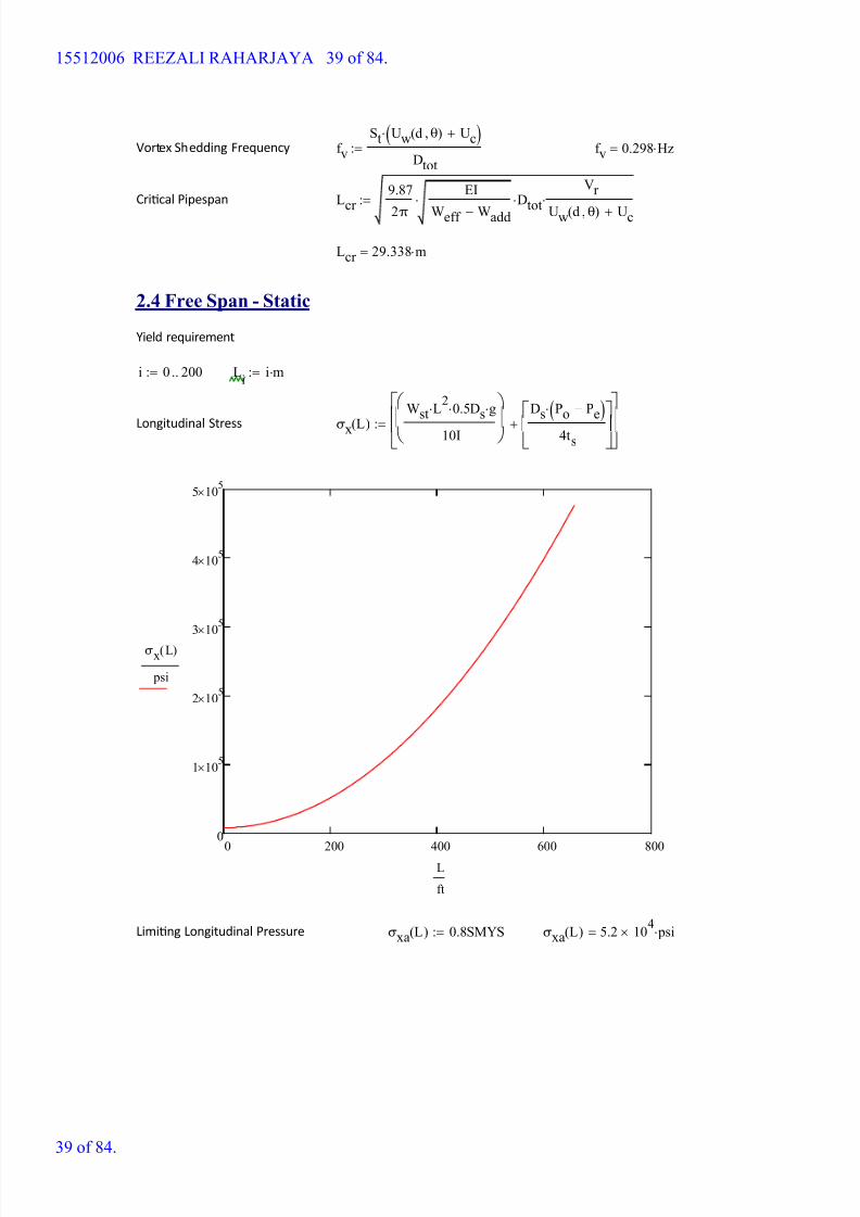
Longitudinal Stress σx L( )
Wst L2
0.5 Ds g
10I
Ds Po Pe-( )
4ts
+
:=
0 200 400 600 800
0
1 105
2 105
3 105
4 105
5 105
σx L( )
psi
L
ft
Liming Longitudinal Pressure σxa L( ) 0.8SMYS:= σxa L( ) 5.2 104
psi=
15512006 REEZALI RAHARJAYA 39 of 84.
39 of 84.
8/15/2019 HW5 2016 15512006
http://slidepdf.com/reader/full/hw5-2016-15512006 40/84
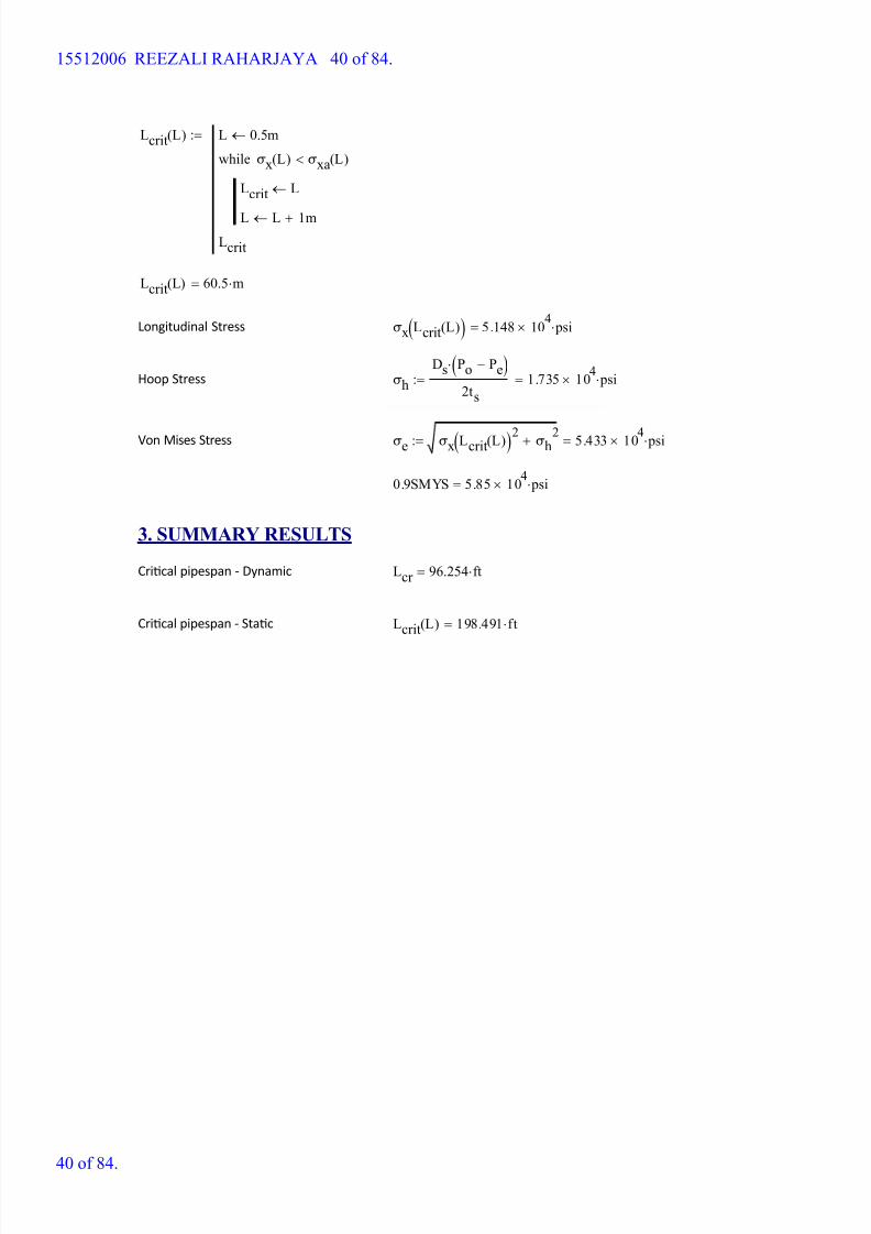
Lcrit L( ) L 0.5m
Lcrit L
L L 1m+
σx L( ) σxa L( )<while
Lcrit
:=
Lcrit L( ) 60.5 m=
Longitudinal Stress σx Lcrit L( )( ) 5.148 104
psi=
Hoop Stress σh
Ds Po Pe-( )
2ts
1.735 104
psi=:=
Von Mises Stress σe σx Lcrit L( )( )2 σh2+ 5.433 104 psi=:=
0.9SMYS 5.85 104
psi=
3. SUMMARY RESULTS
Crical pipespan - Dynamic Lcr 96.254 ft=
Crical pipespan - Stac Lcrit L( ) 198.491 ft=
15512006 REEZALI RAHARJAYA 40 of 84.
40 of 84.
8/15/2019 HW5 2016 15512006
http://slidepdf.com/reader/full/hw5-2016-15512006 41/84
BAGIAN B
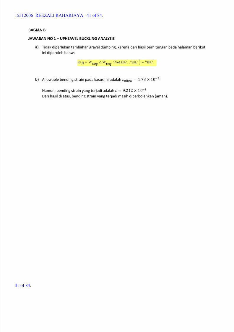
JAWABAN NO 1 – UPHEAVEL BUCKLING ANALYSIS
a)
Tidak diperlukan tambahan gravel dumping, karena dari hasil perhitungan pada halaman berikut
ini diperoleh bahwa
b)
Allowable bending strain pada kasus ini adalah = 1 .73 × 10−
Namun, bending strain yang terjadi adalah = 9.212 × 10⁻⁴
Dari hasil di atas, bending strain yang terjadi masih diperbolehkan (aman).
15512006 REEZALI RAHARJAYA 41 of 84.
41 of 84.
8/15/2019 HW5 2016 15512006
http://slidepdf.com/reader/full/hw5-2016-15512006 42/84
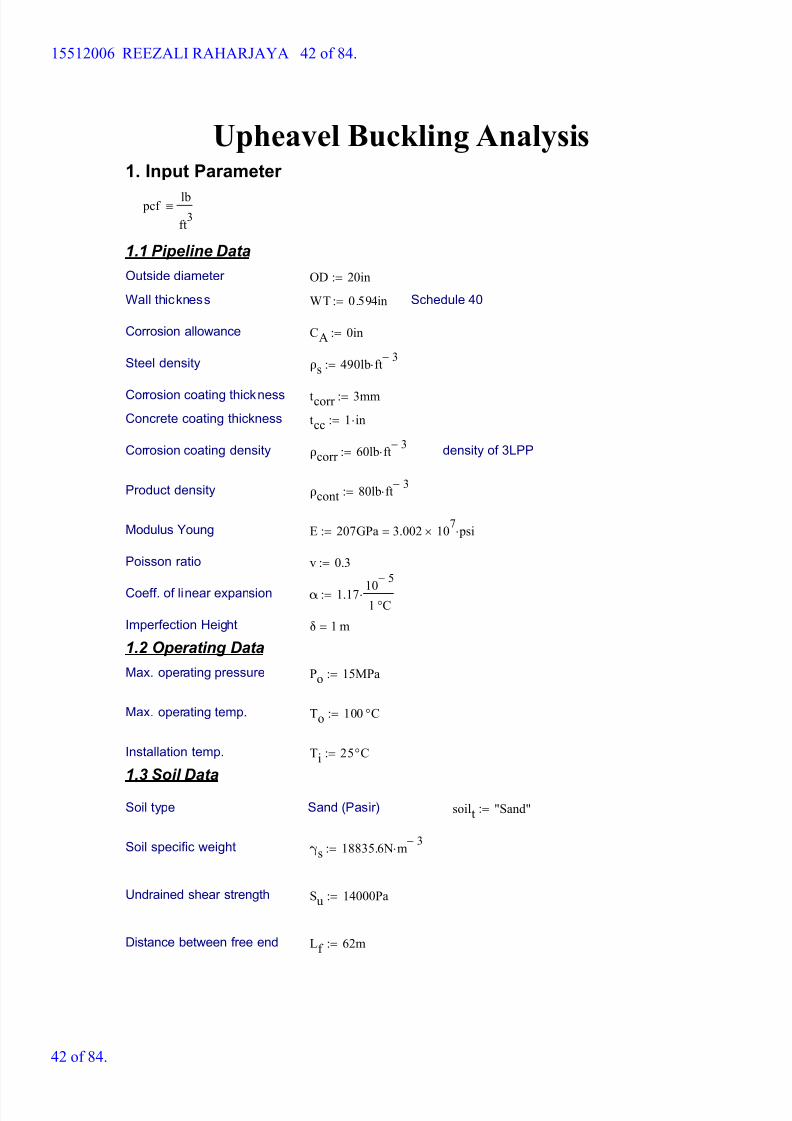
Upheavel Buckling Analysis1. Input Parameter
pcf lb
ft3
1.1 Pipeline Data
Outside diameter OD 20in:=
Wall thickness WT 0.594in:= Schedule 40
Corrosion allowance CA 0in:=
Steel density ρs 490lb ft 3-
:=
Corrosion coating thickness tcorr 3mm:=
Concrete coating thickness tcc 1 in:=
Corrosion coating density ρcorr 60lb ft 3-
:= density of 3LPP
Product density ρcont 80lb ft 3-
:=
Modulus Young E 207GPa 3.002 107
psi=:=
Poisson ratio v 0.3:=
Coeff. of linear expansion α 1.17 10
5-
1 °C:=
Imperfection Height δ 1 m=
1.2 Operating Data
Max. operating pressure Po 15MPa:=
Max. operating temp. To 100 °C:=
Installation temp. Ti 25°C:=
1.3 Soil Data
Soil type Sand (Pasir) soilt "Sand":=
Soil specific weight γs 18835.6N m 3-
:=
Undrained shear strength Su 14000Pa:=
Distance between free end Lf 62m:=
15512006 REEZALI RAHARJAYA 42 of 84.
42 of 84.
8/15/2019 HW5 2016 15512006
http://slidepdf.com/reader/full/hw5-2016-15512006 43/84
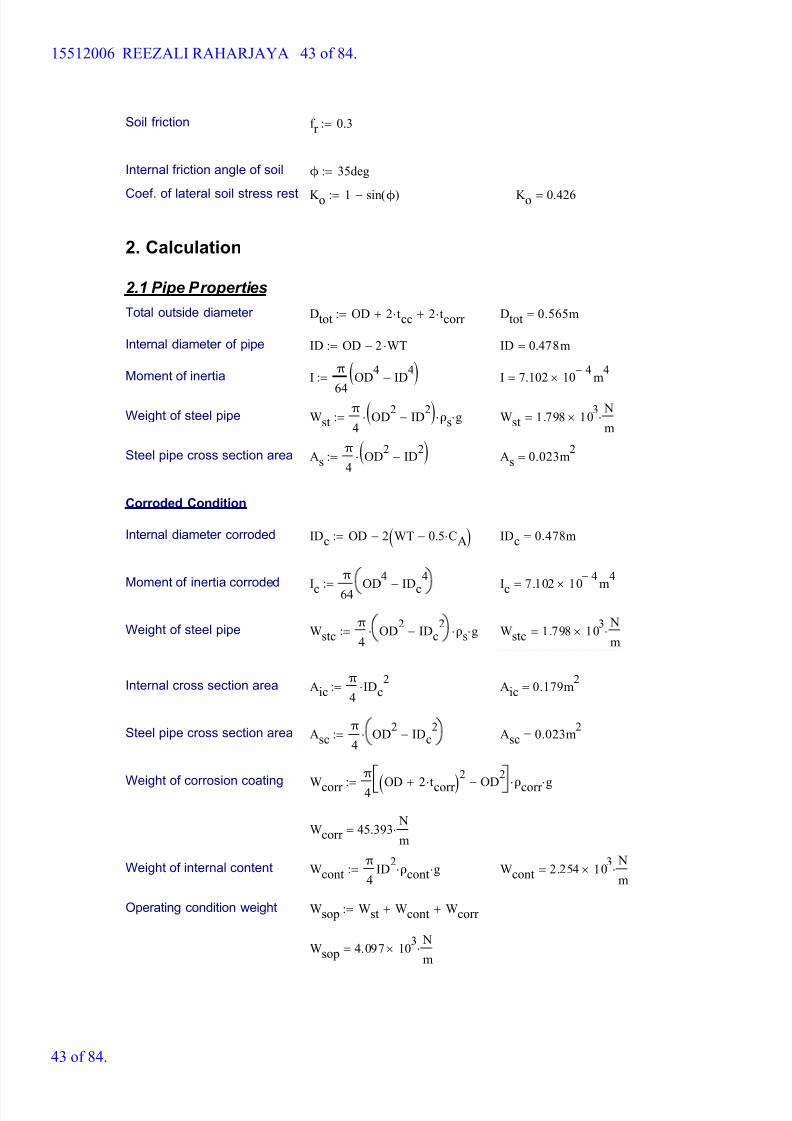
Soil friction f r 0.3:=
Internal friction angle of soil ϕ 35deg:=
Coef. of lateral soil stress rest K o 1 sin ϕ( )-:= K o 0.426=
2. Calculation
2.1 Pipe Properties
Total outside diameter Dtot OD 2 tcc+ 2 tcorr +:= Dtot 0.565m=
Internal diameter of pipe ID OD 2 WT-:= ID 0.478m=
Moment of inertia I π
64
OD4
ID4
-( ):= I 7.102 10 4-
m4
=
Weight of steel pipe Wstπ
4OD
2ID
2-( ) ρs g:= Wst 1.798 10
3
N
m=
Steel pipe cross section area Asπ
4OD
2ID
2-( ):= As 0.023m
2=
Corroded Condition
Internal diameter corroded IDc OD 2 WT 0.5 CA-( )-:= IDc 0.478m=
Moment of inertia corroded Ic
π
64 OD
4
IDc
4
-:= Ic 7.102 10
4-
m
4
=
Weight of steel pipe Wstcπ
4OD
2IDc
2- ρs g:= Wstc 1.798 10
3
N
m=
Internal cross section area Aicπ
4IDc
2:= Aic 0.179m
2=
Steel pipe cross section area Ascπ
4OD
2IDc
2-:= Asc 0.023m
2=
Weight of corrosion coating Wcorr
π
4 OD 2 tcorr +( )2
OD
2
- ρcorr g:=
Wcorr 45.393 N
m=
Weight of internal content Wcontπ
4ID
2ρcont g:= Wcont 2.254 10
3
N
m=
Operating condition weight Wsop Wst Wcont+ Wcorr +:=
Wsop 4.097 103
N
m=
15512006 REEZALI RAHARJAYA 43 of 84.
43 of 84.
8/15/2019 HW5 2016 15512006
http://slidepdf.com/reader/full/hw5-2016-15512006 44/84
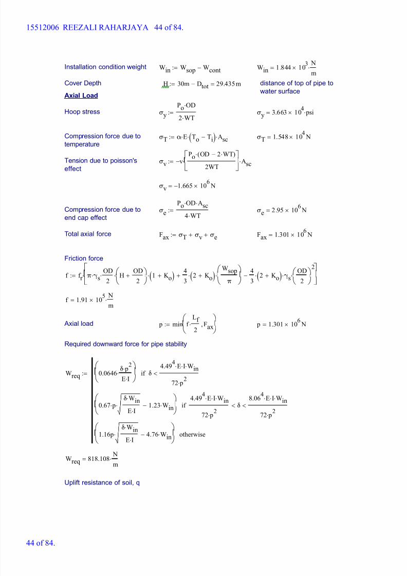
Installation condition weight Win Wsop Wcont-:= Win 1.844 103
N
m=
Cover Depth H 30m Dtot- 29.435m=:= distance of top of pipe to
water surface Axial Load
Hoop stress σy
Po OD
2 WT:= σy 3.663 10
4 psi=
Compression force due to
temperatureσT α E To Ti-( ) Asc:= σT 1.548 10
4 N=
Tension due to poisson's
effectσv v-
Po OD 2 WT-( )
2WT
Asc:=
σv 1.665- 106
N=
Compression force due to
end cap effectσe
Po OD Asc
4 WT:= σe 2.95 10
6 N=
Total axial force Fax σT σv+ σe+:= Fax 1.301 106
N=
Friction force
f f r π γs OD
2 H
OD
2+
1 K o+( ) 4
32 K o+( )
Wsop
π
+ 4
32 K o+( ) γs
OD
2
2
-
:=
f 1.91 10
5
N
m=
Axial load p min f Lf
2 Fax,
:= p 1.301 10
6 N=
Required downward force for pipe stability
Wreq 0.0646 δ p
2
E I
δ
4.494
E I Win
72 p2
<if
0.67 p
δ W
in
E I 1.23 Win-
4.494
E I W
in
72 p2
δ<
8.064
E I W
in
72 p2
<if
1.16pδ Win
E I 4.76 Win-
otherwise
:=
Wreq 818.108 N
m=
Uplift resistance of soil, q
15512006 REEZALI RAHARJAYA 44 of 84.
44 of 84.
8/15/2019 HW5 2016 15512006
http://slidepdf.com/reader/full/hw5-2016-15512006 45/84
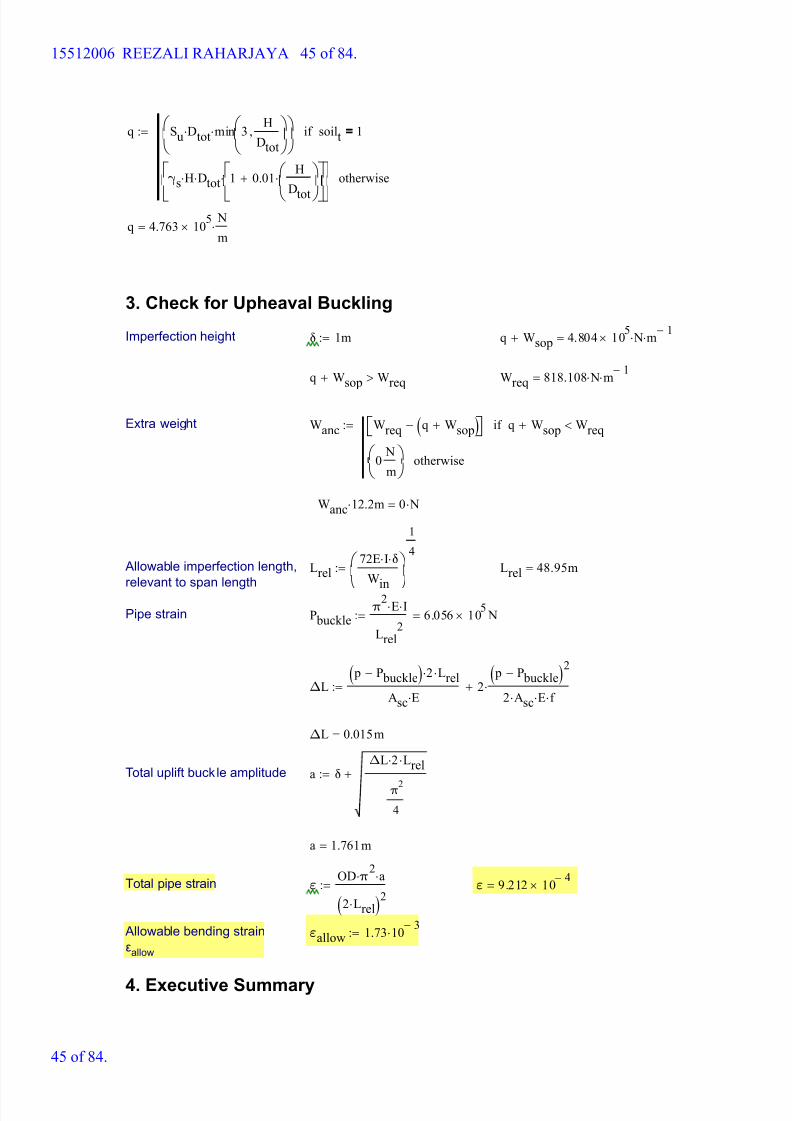
q Su Dtot min 3 H
Dtot
,
soilt 1=if
γs H Dtot 1 0.01 H
Dtot
+
otherwise
:=
q 4.763 105
N
m=
3. Check for Upheaval Buckling
Imperfection height δ 1m:= q Wsop+ 4.804 105
N m 1-
=
q Wsop+ Wreq> Wreq 818.108 N m 1-
=
Extra weight Wanc Wreq q Wsop+( )- q Wsop+ Wreq<if
0 N
m
otherwise
:=
Wanc 12.2 m 0 N=
Allowable imperfection length,
relevant to span lengthLrel
72E I δ
W
in
1
4
:= Lrel 48.95m=
Pipe strain P buckleπ
2E I
Lrel2
6.056 105
N=:=
ΔL p P buckle-( ) 2 Lrel
Asc E 2
p P buckle-( )2
2 Asc E f +:=
ΔL 0.015m=
Total uplift buckle amplitude a δΔL 2 Lrel
π2
4
+:=
a 1.761m=
Total pipe strain ε OD π
2 a
2 Lrel( )2
:= ε 9.212 10 4-
=
Allowable bending strain
εallow
εallow 1.73 10 3-
:=
4. Executive Summary
15512006 REEZALI RAHARJAYA 45 of 84.
45 of 84.
8/15/2019 HW5 2016 15512006
http://slidepdf.com/reader/full/hw5-2016-15512006 46/84
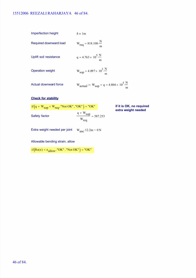
Imperfection height δ 1m
Required downward load Wreq 818.108 N
m=
Uplift soil resistance q 4.763 105
N
m=
Operation weight Wsop 4.097 103
N
m=
Actual downward force Wactual Wsop q+ 4.804 105
N
m=:=
Check for stability
if q Wsop+ Wreq< "Not OK", "OK",( ) "OK"= if it is OK, no required
extra weight needed
Safety factor q Wsop+
Wreq
587.253=
Extra weight needed per joint Wanc 12.2 m 0 N=
Allowable bending strain, allow
if Re ε( ) εallow< "OK", "Not OK",( ) "OK"=
15512006 REEZALI RAHARJAYA 46 of 84.
46 of 84.
8/15/2019 HW5 2016 15512006
http://slidepdf.com/reader/full/hw5-2016-15512006 47/84
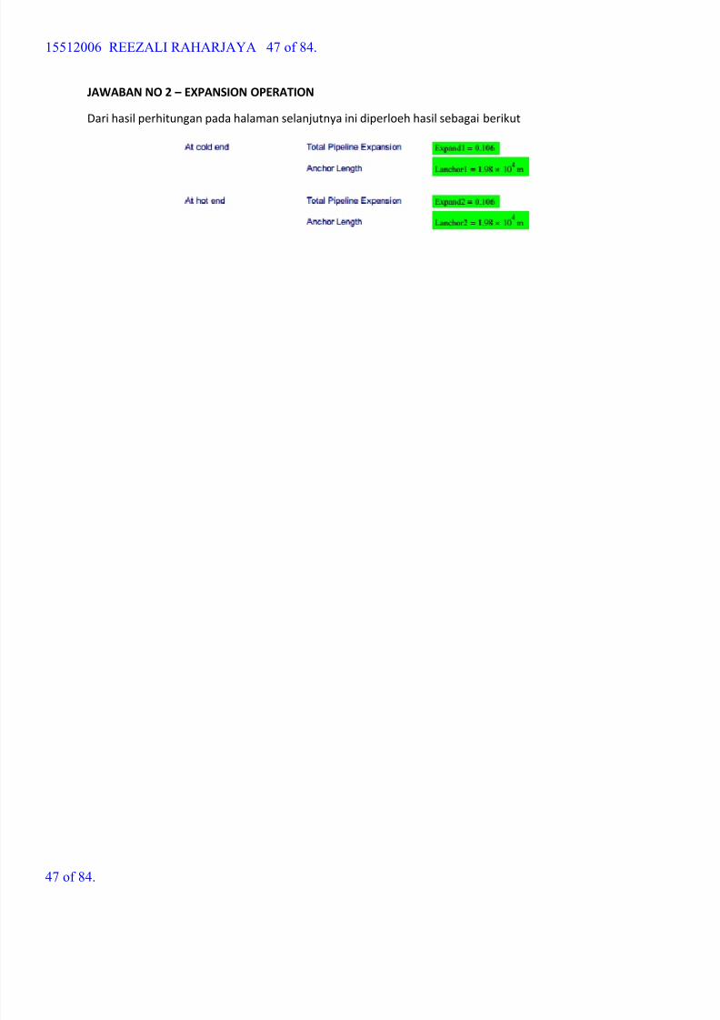
JAWABAN NO 2 – EXPANSION OPERATION
Dari hasil perhitungan pada halaman selanjutnya ini diperloeh hasil sebagai berikut
15512006 REEZALI RAHARJAYA 47 of 84.
47 of 84.
8/15/2019 HW5 2016 15512006
http://slidepdf.com/reader/full/hw5-2016-15512006 48/84
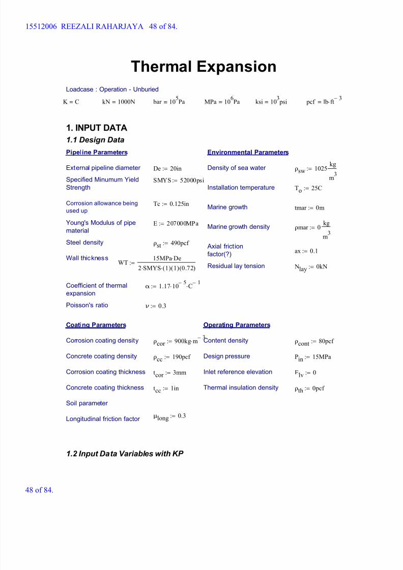
Thermal Expansion
Loadcase : Operation - Unburied
K C kN 1000N bar 105Pa MPa 106Pa ksi 103 psi pcf lb ft 3-
1. INPUT DATA
1.1 Design Data
Pipeline Parameters Environmental Parameters
External pipeline diameter De 20in:= Density of sea water ρsw 1025 kg
m3
:=
Specified Minumum Yield
StrengthSMYS 52000psi:=
Installation temperature To 25C:=
Corrosion allowance being
used upTc 0.125in:=
Marine growth tmar 0m:=
Young's Modulus of pipe
materialE 207000MPa:=
Marine growth density ρmar 0 kg
m3
:=
Steel density ρst 490pcf := Axial friction
factor(?) ax 0.1:=
Wall thicknessWT
15MPa De
2 SMYS 1( ) 1( ) 0.72( ):=
Residual lay tension Nlay 0kN:=
Coefficient of thermal
expansionα 1.17 10
5- C
1-:=
Poisson's ratio ν 0.3:=
Coating Parameters Operating Parameters
Corrosion coating density ρcor 900kg m 3-
:= Content density ρcont 80pcf :=
Concrete coating density ρcc 190pcf := Design pressure Pin 15MPa:=
Corrosion coating thickness tcor 3mm:= Inlet reference elevation Elv 0:=
Concrete coating thickness tcc 1in:= Thermal insulation density ρth 0pcf :=
Soil parameter
μlong 0.3:=Longitudinal friction factor
1.2 Input Data Variables with KP
15512006 REEZALI RAHARJAYA 48 of 84.
48 of 84.
8/15/2019 HW5 2016 15512006
http://slidepdf.com/reader/full/hw5-2016-15512006 49/84
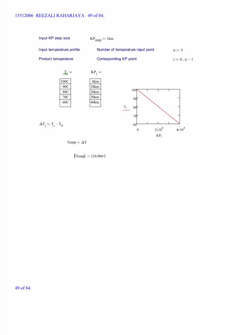
Input KP step size KPstep 1km:=
Input temperature profile Number of temperature input point n 5:=
Product temperature Corresponding KP point i 0 n 1-..:=
Ti
100C
90C
80C
70C
60C
:= KPi
0km
10km
20km
30km
40km
:=
0 2 104
4 104
60
70
80
90
100
Ti
KPi
ΔTi
Ti
To-:=
Temp ΔT:=
Temp 126.984 C=
15512006 REEZALI RAHARJAYA 49 of 84.
49 of 84.
8/15/2019 HW5 2016 15512006
http://slidepdf.com/reader/full/hw5-2016-15512006 50/84
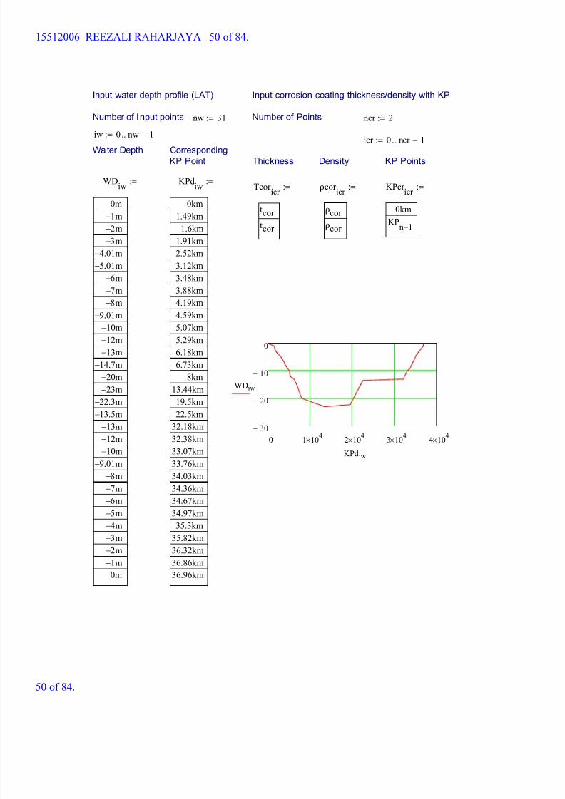
Input water depth profile (LAT)
Number of Input points
Input corrosion coating thickness/density with KP
nw 31:= Number of Points ncr 2:=
iw 0 nw 1-..:=icr 0 ncr 1-..:=
Water Depth Corresponding
KP Point Thickness Density KP Points
WDiw
0m
1- m
2- m
3- m
4.01- m
5.01- m
6- m7- m
8- m
9.01- m
10- m
12- m
13- m
14.7- m
20- m
23- m
22.3- m
13.5- m
13- m
12- m
10- m
9.01- m
8- m
7- m
6- m
5- m
4- m
3- m
2- m
1- m
0m
:= KPdiw
0km
1.49km
1.6km
1.91km
2.52km
3.12km
3.48km3.88km
4.19km
4.59km
5.07km
5.29km
6.18km
6.73km
8km
13.44km
19.5km
22.5km
32.18km
32.38km
33.07km
33.76km
34.03km
34.36km
34.67km
34.97km
35.3km
35.82km
36.32km
36.86km
36.96km
:=Tcor
icr
tcor
tcor
:= ρcor icr
ρcor
ρcor
:= KPcr icr
0km
KPn 1-
:=
0 1 104
2 104
3 104
4 104
30-
20-
10-
0
WDiw
KPdiw
15512006 REEZALI RAHARJAYA 50 of 84.
50 of 84.

8/15/2019 HW5 2016 15512006
http://slidepdf.com/reader/full/hw5-2016-15512006 51/84
Wall thickness and OD profi le with KP Marine growth thickness
Number of Points nwt 2:= Number of points nm 2:=
iwt 0 nwt 1-..:= im 0 nm 1-..:=
Wall Thickness Corresponding KP Marine Growth Corresponding KP Points
WTiwt
WT 10% Tc( )-
WT 10% Tc( )-
:= KPwtiwt
0km
KPn 1-
:= Tmar im
tmar
tmar
:= KPmim
0km
KPn 1-
:=
Input concrete coating thickness with KP Input concrete coating thickness with KP
Number of points ncc 2:= Number of points nlf 11:=
icc 0 ncc 1-..:= ilf 0 nlf 1-..:=
Concrete
Thickness
Corresponding
Kp Points
KPcf ilf
0km
1.91km
5.07km
6.78km
8km
13.44km
19.5km
22.5km32km
34.97km
36.96km
:=μlong
ilf
μlong
μlong
μlong
μlong
μlong
μlong
μlong
μlong
μlong
μlong
μlong
:=
Tconicc
tcc
tcc
:= KPccicc
0km
KPn 1-( )
:=
Thermal Insulation with KP
Number of Points nti 2:= Corroded WT with KP
Number of Points nwtc 2:=iti 0 nti 1-..:=
iwtc 0 nwtc 1-..:=
Additional Weight Corresponding KP Corresponding KPCorroded WT
Tthiti
0in
0in
:= KPthiti
0km
KPn 1-
:=WTc
iwtc WT
iwtc Tc-:= KP
iwtc
0km
KPn 1-
:=
15512006 REEZALI RAHARJAYA 51 of 84.
51 of 84.
8/15/2019 HW5 2016 15512006
http://slidepdf.com/reader/full/hw5-2016-15512006 52/84
Jacket Material with KP
Number of Points nti 2:=
iti 0 nti 1-..:=
Additional Weight Corresponding KP
Tjiti
0in
0in
:= KPthiti
KP0
KPn 1-
:=
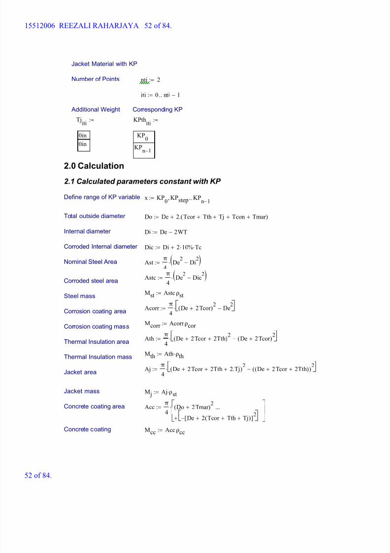
2.0 Calculation
2.1 Calculated parameters constant with KP
Define range of KP variable x KP0
KPstep, KPn 1-
..:=
Total outside diameter Do De 2. Tcor Tth+ Tj+ Tcon+ Tmar +( )+:=
Internal diameter Di De 2WT-:=
Corroded Internal diameter Dic Di 2 10 % Tc+:=
Nominal Steel Area Ast π
4De
2Di
2-( ):=
Astc π
4De
2Dic
2-( ):=
Corroded steel area
Mst Astc ρst:=Steel mass
Acorr π
4De 2 Tcor +( )
2De
2-:=
Corrosion coating area
Mcorr Acorr ρcor :=Corrosion coating mass
Ath π
4De 2 Tcor + 2Tth+( )
2De 2 Tcor +( )
2-:=
Thermal Insulation area
Mth Ath ρth:=Thermal Insulation mass
Aj π
4De 2 Tcor + 2Tth+ 2.Tj+( )
2De 2 Tcor + 2Tth+( )( )
2-:=
Jacket area
Jacket mass M j Aj ρst:=
Concrete coating area Acc π
4Do 2 Tmar +( )
2
De 2 Tcor Tth+ Tj+( )+[ ]2
-+
...
:=
Concrete coating Mcc Acc ρcc:=
15512006 REEZALI RAHARJAYA 52 of 84.
52 of 84.
8/15/2019 HW5 2016 15512006
http://slidepdf.com/reader/full/hw5-2016-15512006 53/84
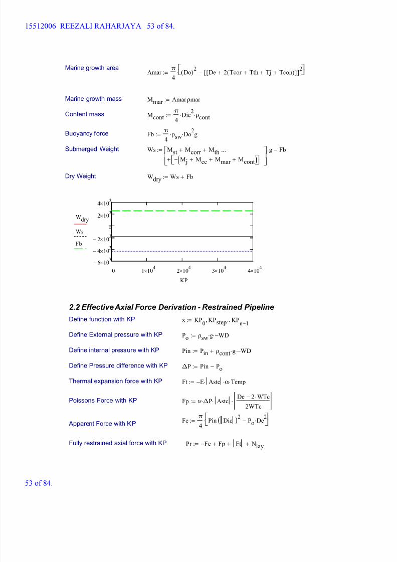
Marine growth areaAmar
π
4Do( )
2De 2 Tcor Tth+ Tj+ Tcon+( )+[ ][ ]
2-:=
Marine growth mass Mmar Amar ρmar :=
Content mass Mcontπ
4Dic
2 ρcont:=
Buoyancy force Fbπ
4ρsw Do
2 g:=
Submerged Weight Ws Mst Mcorr + Mth+
M j Mcc+ Mmar + Mcont+( )-+
...
g Fb-:=
Dry Weight Wdry Ws Fb+:=
0 1 104
2 104
3 104
4 104
6- 103
4- 103
2- 103
0
2 103
4 103
Wdry
Ws
Fb
KP
2.2 Effective Axial Force Derivation - Restrained Pipeline
Define function with KP x KP0
KPstep, KPn 1-
..:=
Define External pressure with KP Po ρsw g WD-:=
Define internal pressure with KP Pin Pin ρcont g WD-+:=
Define Pressure difference with KP ΔP Pin Po-:=
Thermal expansion force with KP Ft E- Astc α Temp:=
Poissons Force with KP Fp ν ΔP Astc De 2 WTc-
2WTc:=
Feπ
4Pin Dic( )
2Po De
2-:=
Apparent Force with KP
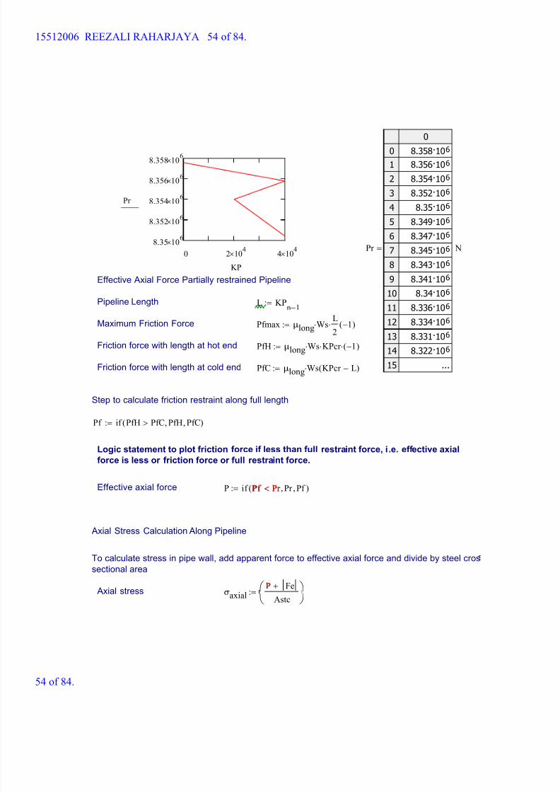
Fully restrained axial force with KP Pr Fe- Fp+ Ft+ Nlay+:=
15512006 REEZALI RAHARJAYA 53 of 84.
53 of 84.
8/15/2019 HW5 2016 15512006
http://slidepdf.com/reader/full/hw5-2016-15512006 54/84
8/15/2019 HW5 2016 15512006
http://slidepdf.com/reader/full/hw5-2016-15512006 55/84
8/15/2019 HW5 2016 15512006
http://slidepdf.com/reader/full/hw5-2016-15512006 56/84
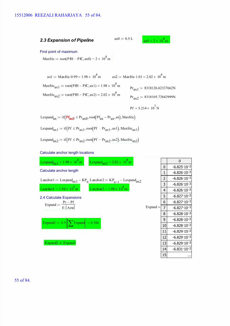
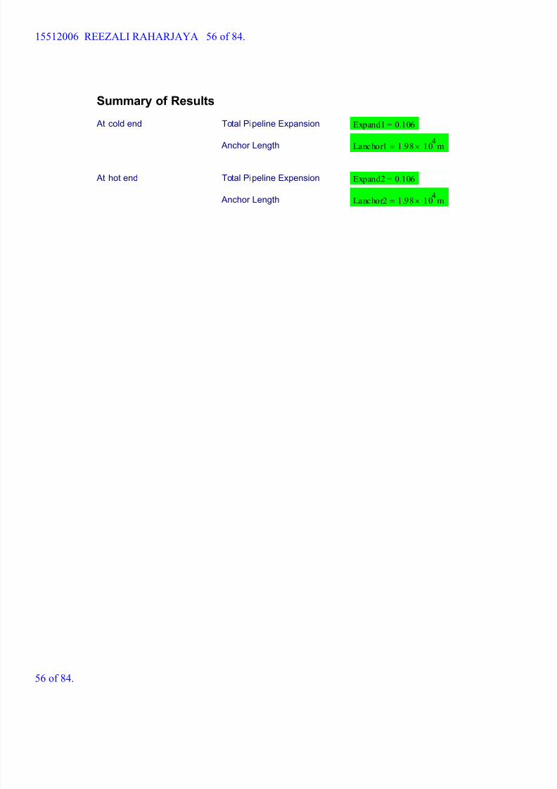
Summary of Results
At cold end Total Pipeline Expansion Expand1 0.106=
Anchor Length Lanchor1 1.98 104
m=
At hot end Total Pipeline Expension Expand2 0.106=
Anchor Length Lanchor2 1.98 104
m=
15512006 REEZALI RAHARJAYA 56 of 84.
56 of 84.
8/15/2019 HW5 2016 15512006
http://slidepdf.com/reader/full/hw5-2016-15512006 57/84
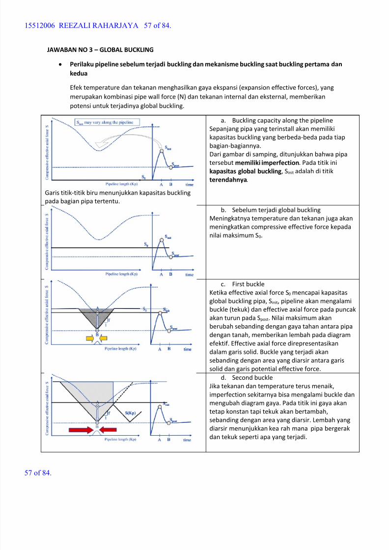
JAWABAN NO 3 – GLOBAL BUCKLING
Perilaku pipeline sebelum terjadi buckling dan mekanisme buckling saat buckling pertama dan
kedua
Efek temperature dan tekanan menghasilkan gaya ekspansi (expansion effective forces), yang
merupakan kombinasi pipe wall force (N) dan tekanan internal dan eksternal, memberikanpotensi untuk terjadinya global buckling.
Garis titik-titik biru menunjukkan kapasitas bucklingpada bagian pipa tertentu.
a.
Buckling capacity along the pipeline
Sepanjang pipa yang terinstall akan memiliki
kapasitas buckling yang berbeda-beda pada tiap
bagian-bagiannya.
Dari gambar di samping, ditunjukkan bahwa pipa
tersebut memiliki imperfection. Pada titik ini
kapasitas global buckling, Sinit adalah di titik
terendahnya.
b.
Sebelum terjadi global buckling
Meningkatnya temperature dan tekanan juga akan
meningkatkan compressive effective force kepada
nilai maksimum S0.
c.
First buckle
Ketika effective axial force S0 mencapai kapasitas
global buckling pipa, Sinit, pipeline akan mengalami
buckle (tekuk) dan effective axial force pada puncak
akan turun pada Spost. Nilai maksimum akan
berubah sebanding dengan gaya tahan antara pipa
dengan tanah, memberikan lembah pada diagram
efektif. Effective axial force direpresentasikan
dalam garis solid. Buckle yang terjadi akan
sebanding dengan area yang diarsir antara garis
solid dan garis potential effective force.
d.
Second buckle
Jika tekanan dan temperature terus menaik,imperfection sekitarnya bisa mengalami buckle dan
mengubah diagram gaya. Pada titik ini gaya akan
tetap konstan tapi tekuk akan bertambah,
sebanding dengan area yang diarsir. Lembah yang
diarsir menunjukkan kea rah mana pipa bergerak
dan tekuk seperti apa yang terjadi.
15512006 REEZALI RAHARJAYA 57 of 84.
57 of 84.
8/15/2019 HW5 2016 15512006
http://slidepdf.com/reader/full/hw5-2016-15512006 58/84
8/15/2019 HW5 2016 15512006
http://slidepdf.com/reader/full/hw5-2016-15512006 59/84
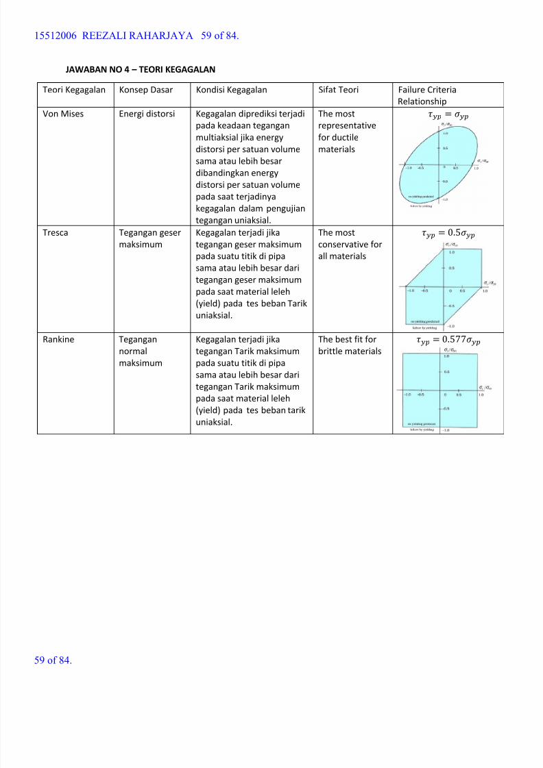
JAWABAN NO 4 – TEORI KEGAGALAN
Teori Kegagalan Konsep Dasar Kondisi Kegagalan Sifat Teori Failure Criteria
Relationship
Von Mises Energi distorsi Kegagalan diprediksi terjadi
pada keadaan tegangan
multiaksial jika energydistorsi per satuan volume
sama atau lebih besar
dibandingkan energy
distorsi per satuan volume
pada saat terjadinya
kegagalan dalam pengujian
tegangan uniaksial.
The most
representative
for ductilematerials
=
Tresca Tegangan geser
maksimum
Kegagalan terjadi jika
tegangan geser maksimum
pada suatu titik di pipa
sama atau lebih besar daritegangan geser maksimum
pada saat material leleh
(yield) pada tes beban Tarik
uniaksial.
The most
conservative for
all materials
= 0.5
Rankine Tegangan
normal
maksimum
Kegagalan terjadi jika
tegangan Tarik maksimum
pada suatu titik di pipa
sama atau lebih besar dari
tegangan Tarik maksimum
pada saat material leleh
(yield) pada tes beban tarik
uniaksial.
The best fit for
brittle materials
= 0.577
15512006 REEZALI RAHARJAYA 59 of 84.
59 of 84.
8/15/2019 HW5 2016 15512006
http://slidepdf.com/reader/full/hw5-2016-15512006 60/84
LAMPIRAN
15512006 REEZALI RAHARJAYA 60 of 84.
60 of 84.
8/15/2019 HW5 2016 15512006
http://slidepdf.com/reader/full/hw5-2016-15512006 61/84
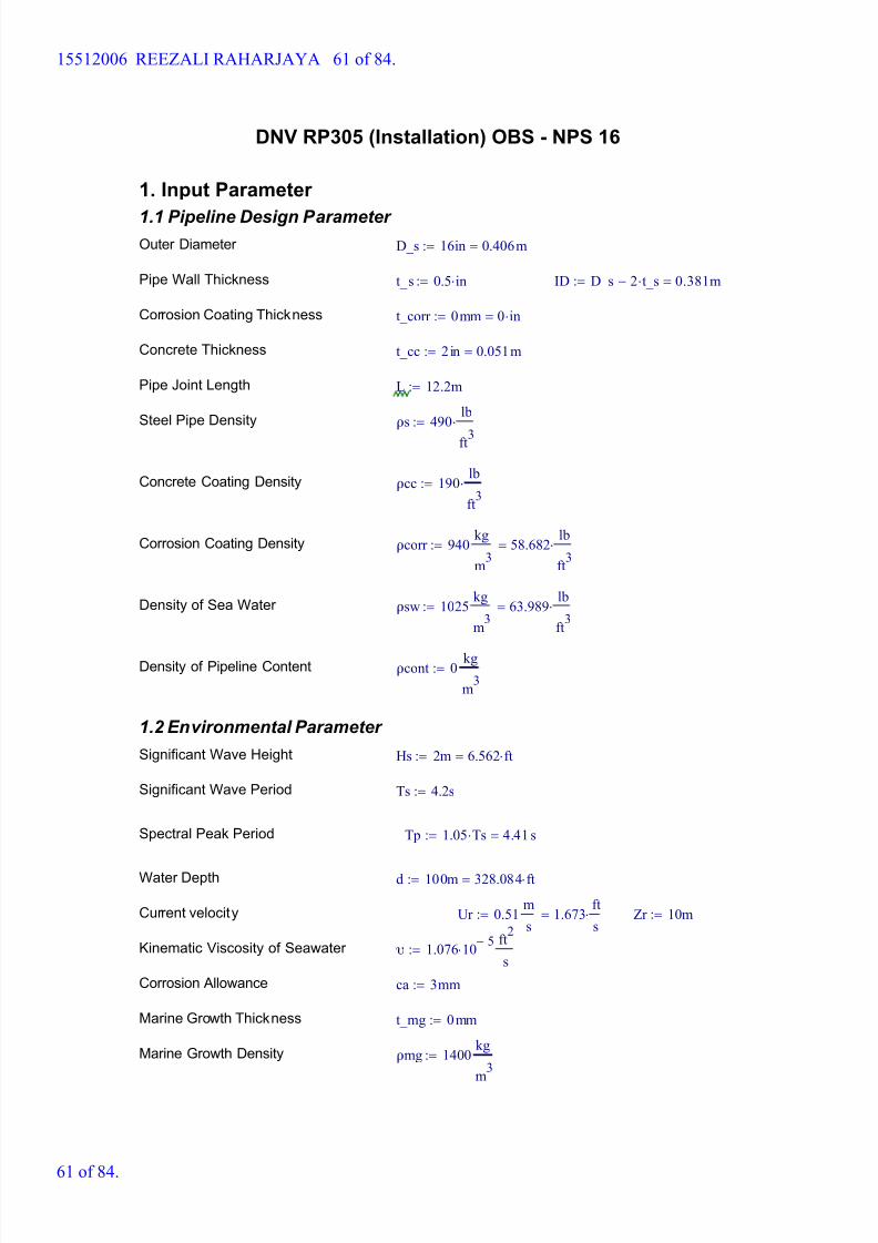
DNV RP305 (Installation) OBS - NPS 16
1. Input Parameter
1.1 Pipeline Design Parameter Outer Diameter D_s 16in 0.406m=:=
Pipe Wall Thickness t_s 0.5 in:= ID D_s 2 t_s- 0.381m=:=
Corrosion Coating Thickness t_corr 0mm 0 in=:=
Concrete Thickness t_cc 2in 0.051m=:=
Pipe Joint Length L 12.2m:=
Steel Pipe Density ρs 490 lb
ft3
:=
Concrete Coating Density ρcc 190 lb
ft3
:=
Corrosion Coating Density ρcorr 940 kg
m3
58.682 lb
ft3
=:=
Density of Sea Water ρsw 1025 kg
m3
63.989 lb
ft3
=:=
Density of Pipeline Content ρcont 0 kg
m3
:=
1.2 Environmental Parameter
Significant Wave Height Hs 2m 6.562 ft=:=
Significant Wave Period Ts 4.2s:=
Spectral Peak Period Tp 1.05 Ts 4.41 s=:=
Water Depth d 100m 328.084 ft=:=
Current velocity Ur 0.51 m
s1.673
ft
s=:= Zr 10m:=
Kinematic Viscosity of Seawater υ 1.076 10 5-
ft
2
s:=
Corrosion Allowance ca 3mm:=
Marine Growth Thickness t_mg 0mm:=
Marine Growth Density ρmg 1400 kg
m3
:=
15512006 REEZALI RAHARJAYA 61 of 84.
61 of 84.

8/15/2019 HW5 2016 15512006
http://slidepdf.com/reader/full/hw5-2016-15512006 62/84
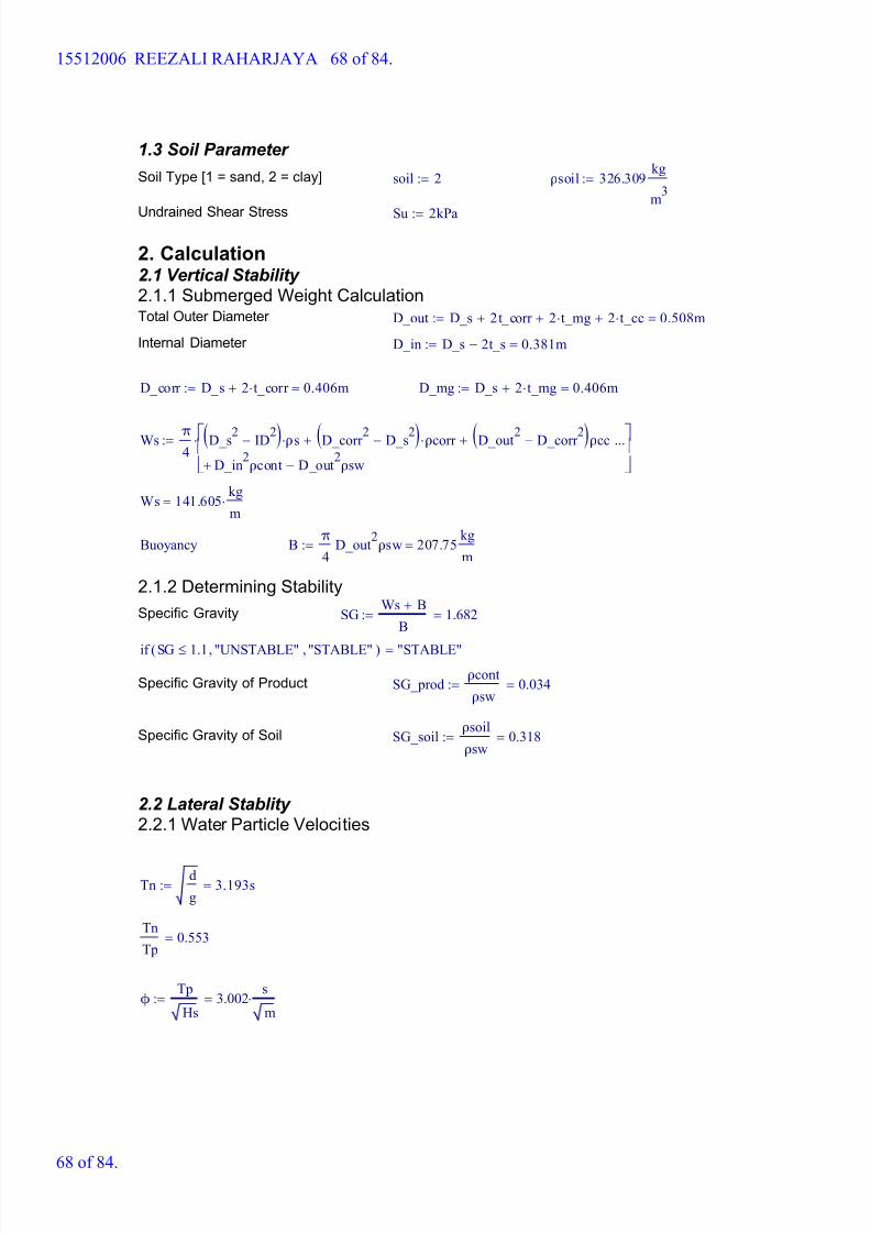
1.3 Soil Parameter
Soil Type [1 = sand, 2 = clay] soil 2:= ρsoil 326.309 kg
m3
:=
Undrained Shear Stress Su 2kPa:=
2. Calculation2.1 Vertical Stability 2.1.1 Submerged Weight CalculationTotal Outer Diameter D_out D_s 2t_corr + 2 t_mg+ 2 t_cc+ 0.508m=:=
Internal Diameter D_in D_s 2t_s- 0.381m=:=
D_corr D_s 2 t_corr + 0.406m=:= D_mg D_s 2 t_mg+ 0.406m=:=
Ws π4
D_s2 ID2-( ) ρs D_corr 2 D_s2-( ) ρcorr + D_out2 D_corr 2-( )ρcc+
D_in2
ρcont D_out2
ρsw-+
...
:=
Ws 137.614 kg
m=
Buoyancy B π
4D_out
2ρsw 207.75
kg
m=:=
2.1.2 Determining Stability
Specific Gravity SG Ws B+
B1.662=:=
if SG 1.1 "UNSTABLE", "STABLE",( ) "STABLE"=
Specific Gravity of Product SG_prod ρcont
ρsw0=:=
Specific Gravity of Soil SG_soil ρsoil
ρsw0.318=:=
2.2 Lateral Stablity 2.2.1 Water Particle Velocities
Tn d
g3.193s=:=
Tn
Tp0.724=
ϕ Tp
Hs3.118
s
m=:=
15512006 REEZALI RAHARJAYA 62 of 84.
62 of 84.

8/15/2019 HW5 2016 15512006
http://slidepdf.com/reader/full/hw5-2016-15512006 63/84
Peakedness Parameter γ 5 ϕ 3.6 s
mif
1 ϕ 5 s
m
if
3.3 otherwise
5=:=
From Fig. 2-1 DNV RP E305
Tn
Tp0.724=
Us 0.000001 Hs
Tn6.263 10
7-
m
s=:= Us:kecepatan partikel air signifikan akibat gelombang
15512006 REEZALI RAHARJAYA 63 of 84.
63 of 84.

8/15/2019 HW5 2016 15512006
http://slidepdf.com/reader/full/hw5-2016-15512006 64/84
From Fig. 2-1 DNV RP E305
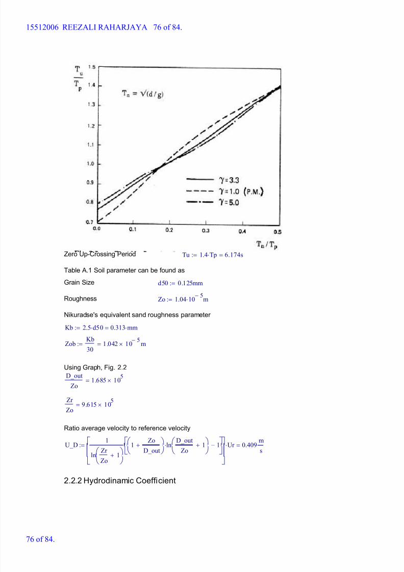
Zero Up-Crossing Period Tu 1.4 Tp 6.174s=:=
Table A.1 Soil parameter can be found as
Grain Size d50 0.125mm:=
Roughness Zo 1.04 10
5-m:=
Nikuradse's equivalent sand roughness parameter
Kb 2.5 d50 0.313 mm=:=
Zob Kb
301.042 10
5- m=:=
Using Graph, Fig. 2.2
D_out
Zo4.885 10
4=
Zr Zo
9.615 105=
Ratio average velocity to reference velocity
U_D 1
ln Zr
Zo1+
1 Zo
D_out+
ln D_out
Zo1+
1-
Ur 0.363 m
s=:=
2.2.2 Hydrodinamic Coefficient
15512006 REEZALI RAHARJAYA 64 of 84.
64 of 84.

8/15/2019 HW5 2016 15512006
http://slidepdf.com/reader/full/hw5-2016-15512006 65/84
Wave Particle Acceleration As 2 π Us
Tu6.374 10
7-
m
s2
=:=
Current to Wave Velocity M U_D
Us5.791 10
5=:=
KC Number K Us Tu
D_out7.612 10
6-=:=
Reynold's Number Re U_D Us+( ) D_out
υ1.843 10
5=:=
Hydrodynamics Coefficient
Cd 1.2 Re 3 105
< M 0.8if
0.7 otherwise
1.2=:=
CL 0.9:=
CM 3.29:=
Soil Coefficient
Clay Soil
Ratio = 1/S Ratio D_out Su
Ws g 0.753=:=
From Figure 5.11 (Friction Factor = μc)
μc 0.24:=
Sand Soil
μs 0:=
Friction Factor Coefficient
μ μs soil 1=if
μc otherwise
:=
μ 0.24=
Calibration Factor
M 5.791 105
=
K 7.612 10 6-
=
Fw 1:=From Fig. 5.12
2.2.3 Lateral Stability Calculation
Hydrodynamic Forces and Required Submerged Weight
15512006 REEZALI RAHARJAYA 65 of 84.
65 of 84.
8/15/2019 HW5 2016 15512006
http://slidepdf.com/reader/full/hw5-2016-15512006 66/84
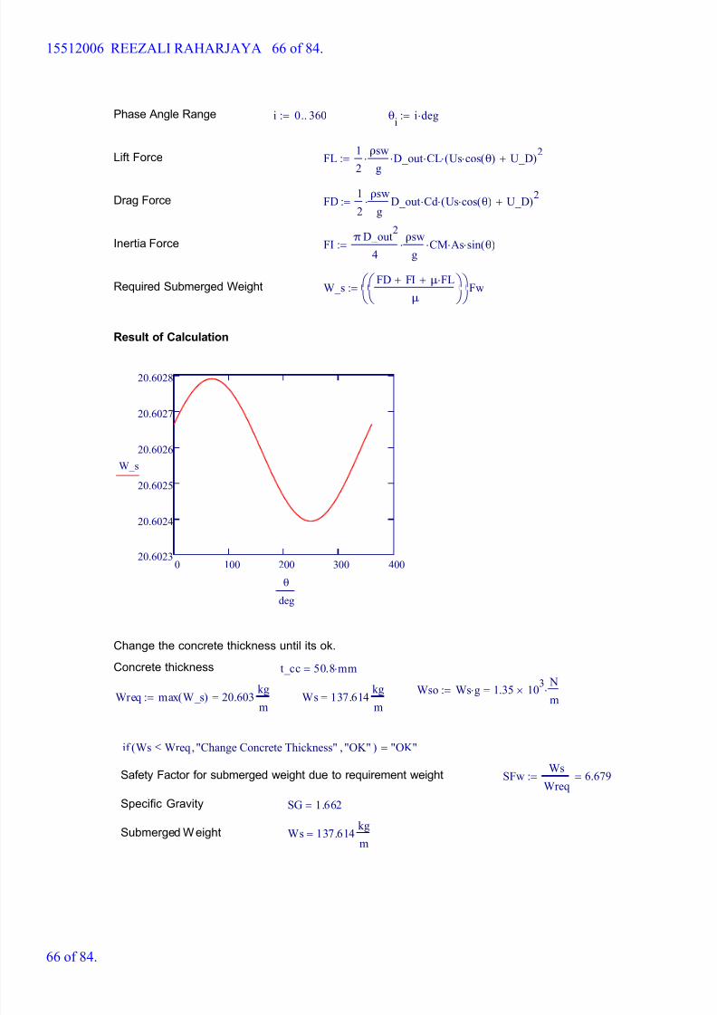
Phase Angle Range i 0 360..:= θi
i deg:=
Lift Force FL 1
2
ρsw
g D_out CL Us cos θ( ) U_D+( )
2:=
Drag Force FD 1
2
ρsw
g D_out Cd Us cos θ( ) U_D+( )
2:=
Inertia Force FI π D_out
2
4
ρsw
g CM As sin θ( ):=
Required Submerged Weight W_s FD FI+ μ FL+
μ
Fw:=
Result of Calculation
0 100 200 300 40020.6023
20.6024
20.6025
20.6026
20.6027
20.6028
W_s
θ
deg
Change the concrete thickness until its ok.
Concrete thickness t_cc 50.8 mm=
Wso Ws g 1.35 103
N
m=:=
Wreq max W_s( ) 20.603 kg
m
=:= Ws 137.614 kg
m
=
if Ws Wreq "Change Concrete Thickness", "OK",( ) "OK"=
Safety Factor for submerged weight due to requirement weight SFw Ws
Wreq6.679=:=
Specific Gravity SG 1.662=
Submerged Weight Ws 137.614 kg
m=
15512006 REEZALI RAHARJAYA 66 of 84.
66 of 84.

8/15/2019 HW5 2016 15512006
http://slidepdf.com/reader/full/hw5-2016-15512006 67/84
DNV RP305 (Operation) OBS - NPS 16
1. Input Parameter
1.1 Pipeline Design Parameter Outer Diameter D_s 16in 0.406m=:=
Pipe Wall Thickness t_s 0.5 in:= ID D_s 2 t_s- 0.381m=:=
Corrosion Coating Thickness t_corr 0mm 0 in=:=
Concrete Thickness t_cc 2in 0.051m=:=
Pipe Joint Length L 12.2m:=
Steel Pipe Density ρs 490 lb
ft3
:=
Concrete Coating Density ρcc 190 lb
ft3
:=
Corrosion Coating Density ρcorr 940 kg
m3
58.682 lb
ft3
=:=
Density of Sea Water ρsw 1025 kg
m3
63.989 lb
ft3
=:=
Density of Pipeline Content ρcont 35 kg
m3
:=
1.2 Environmental Parameter
Significant Wave Height Hs 3.7m 12.139 ft=:=
Significant Wave Period Ts 5.5s:=
Spectral Peak Period Tp 1.05 Ts 5.775s=:=
Water Depth d 100m 328.084 ft=:=
Current velocity Ur 0.63 m
s2.067
ft
s=:= Zr 10m:=
Kinematic Viscosity of Seawater υ 1.076 10 5-
ft
2
s:=
Corrosion Allowance ca 3mm:=
Marine Growth Thickness t_mg 0mm:=
Marine Growth Density ρmg 1400 kg
m3
:=
15512006 REEZALI RAHARJAYA 67 of 84.
67 of 84.
8/15/2019 HW5 2016 15512006
http://slidepdf.com/reader/full/hw5-2016-15512006 68/84
1.3 Soil Parameter
Soil Type [1 = sand, 2 = clay] soil 2:= ρsoil 326.309 kg
m3
:=
Undrained Shear Stress Su 2kPa:=
2. Calculation2.1 Vertical Stability 2.1.1 Submerged Weight CalculationTotal Outer Diameter D_out D_s 2t_corr + 2 t_mg+ 2 t_cc+ 0.508m=:=
Internal Diameter D_in D_s 2t_s- 0.381m=:=
D_corr D_s 2 t_corr + 0.406m=:= D_mg D_s 2 t_mg+ 0.406m=:=
Ws π4
D_s2 ID2-( ) ρs D_corr 2 D_s2-( ) ρcorr + D_out2 D_corr 2-( )ρcc+
D_in2
ρcont D_out2
ρsw-+
...
:=
Ws 141.605 kg
m=
Buoyancy B π
4D_out
2ρsw 207.75
kg
m=:=
2.1.2 Determining Stability
Specific Gravity SG Ws B+
B1.682=:=
if SG 1.1 "UNSTABLE", "STABLE",( ) "STABLE"=
Specific Gravity of Product SG_prod ρcont
ρsw0.034=:=
Specific Gravity of Soil SG_soil ρsoil
ρsw0.318=:=
2.2 Lateral Stablity 2.2.1 Water Particle Velocities
Tn d
g3.193s=:=
Tn
Tp0.553=
ϕ Tp
Hs3.002
s
m=:=
15512006 REEZALI RAHARJAYA 68 of 84.
68 of 84.

8/15/2019 HW5 2016 15512006
http://slidepdf.com/reader/full/hw5-2016-15512006 69/84
Peakedness Parameter γ 5 ϕ 3.6 s
mif
1 ϕ 5 s
m
if
3.3 otherwise
5=:=
From Fig. 2-1 DNV RP E305
Tn
Tp0.553=
Us 0.000001 Hs
Tn1.159 10
6-
m
s=:= Us:kecepatan partikel air signifikan akibat gelombang
15512006 REEZALI RAHARJAYA 69 of 84.
69 of 84.

8/15/2019 HW5 2016 15512006
http://slidepdf.com/reader/full/hw5-2016-15512006 70/84
From Fig. 2-1 DNV RP E305
Zero Up-Crossing Period Tu 1.4 Tp 8.085s=:=
Table A.1 Soil parameter can be found as
Grain Size d50 0.125mm:=
Roughness Zo 1.04 10
5-m:=
Nikuradse's equivalent sand roughness parameter
Kb 2.5 d50 0.313 mm=:=
Zob Kb
301.042 10
5- m=:=
Using Graph, Fig. 2.2
D_out
Zo4.885 10
4=
Zr Zo
9.615 105=
Ratio average velocity to reference velocity
U_D 1
ln Zr
Zo1+
1 Zo
D_out+
ln D_out
Zo1+
1-
Ur 0.448 m
s=:=
2.2.2 Hydrodinamic Coefficient
15512006 REEZALI RAHARJAYA 70 of 84.
70 of 84.

8/15/2019 HW5 2016 15512006
http://slidepdf.com/reader/full/hw5-2016-15512006 71/84
Wave Particle Acceleration As 2 π Us
Tu9.005 10
7-
m
s2
=:=
Current to Wave Velocity M U_D
Us3.867 10
5=:=
KC Number K Us Tu
D_out1.844 10
5-=:=
Reynold's Number Re U_D Us+( ) D_out
υ2.277 10
5=:=
Hydrodynamics Coefficient
Cd 1.2 Re 3 105
< M 0.8if
0.7 otherwise
1.2=:=
CL 0.9:=
CM 3.29:=
Soil Coefficient
Clay Soil
Ratio = 1/S Ratio D_out Su
Ws g 0.732=:=
From Figure 5.11 (Friction Factor = μc)
μc 0.24:=
Sand Soil
μs 0:=
Friction Factor Coefficient
μ μs soil 1=if
μc otherwise
:=
μ 0.24=
Calibration Factor
M 3.867 105
=
K 1.844 10 5-
=
Fw 1:=From Fig. 5.12
2.2.3 Lateral Stability Calculation
Hydrodynamic Forces and Required Submerged Weight
15512006 REEZALI RAHARJAYA 71 of 84.
71 of 84.
8/15/2019 HW5 2016 15512006
http://slidepdf.com/reader/full/hw5-2016-15512006 72/84
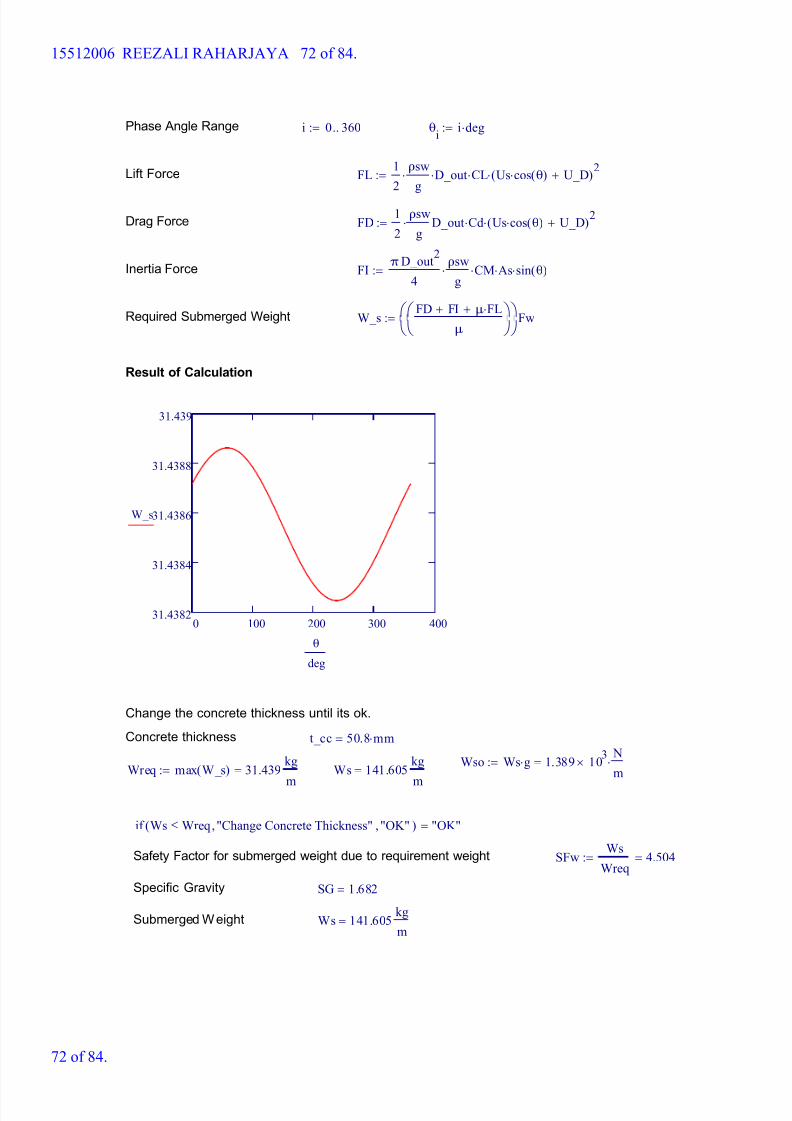
Phase Angle Range i 0 360..:= θi
i deg:=
Lift Force FL 1
2
ρsw
g D_out CL Us cos θ( ) U_D+( )
2:=
Drag Force FD 1
2
ρsw
g D_out Cd Us cos θ( ) U_D+( )
2:=
Inertia Force FI π D_out
2
4
ρsw
g CM As sin θ( ):=
Required Submerged Weight W_s FD FI+ μ FL+
μ
Fw:=
Result of Calculation
0 100 200 300 40031.4382
31.4384
31.4386
31.4388
31.439
W_s
θ
deg
Change the concrete thickness until its ok.
Concrete thickness t_cc 50.8 mm=
Wso Ws g 1.389 103
N
m=:=
Wreq max W_s( ) 31.439 kg
m
=:= Ws 141.605 kg
m
=
if Ws Wreq "Change Concrete Thickness", "OK",( ) "OK"=
Safety Factor for submerged weight due to requirement weight SFw Ws
Wreq4.504=:=
Specific Gravity SG 1.682=
Submerged Weight Ws 141.605 kg
m=
15512006 REEZALI RAHARJAYA 72 of 84.
72 of 84.
8/15/2019 HW5 2016 15512006
http://slidepdf.com/reader/full/hw5-2016-15512006 73/84
DNV RP305 (Installation) OBS - NPS 60
1. Input Parameter
1.1 Pipeline Design Parameter Outer Diameter D_s 60in 1.524m=:=
Pipe Wall Thickness t_s 1 in:= ID D_s 2 t_s- 1.473m=:=
Corrosion Coating Thickness t_corr 0mm 0 in=:=
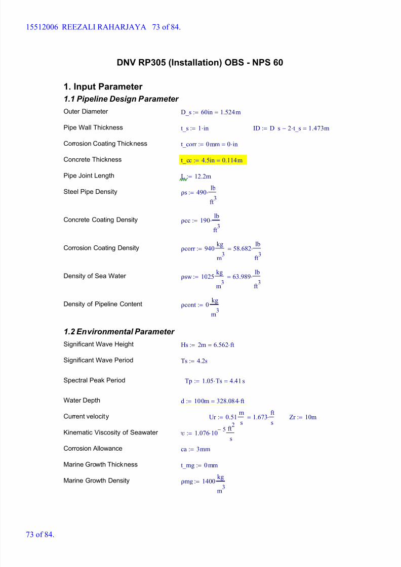
Concrete Thickness t_cc 4.5in 0.114m=:=
Pipe Joint Length L 12.2m:=
Steel Pipe Density ρs 490 lb
ft3
:=
Concrete Coating Density ρcc 190 lb
ft3
:=
Corrosion Coating Density ρcorr 940 kg
m3
58.682 lb
ft3
=:=
Density of Sea Water ρsw 1025 kg
m3
63.989 lb
ft3
=:=
Density of Pipeline Content ρcont 0 kg
m3
:=
1.2 Environmental Parameter
Significant Wave Height Hs 2m 6.562 ft=:=
Significant Wave Period Ts 4.2s:=
Spectral Peak Period Tp 1.05 Ts 4.41 s=:=
Water Depth d 100m 328.084 ft=:=
Current velocity Ur 0.51 m
s1.673
ft
s=:= Zr 10m:=
Kinematic Viscosity of Seawater υ 1.076 10 5-
ft
2
s:=
Corrosion Allowance ca 3mm:=
Marine Growth Thickness t_mg 0mm:=
Marine Growth Density ρmg 1400 kg
m3
:=
15512006 REEZALI RAHARJAYA 73 of 84.
73 of 84.
8/15/2019 HW5 2016 15512006
http://slidepdf.com/reader/full/hw5-2016-15512006 74/84
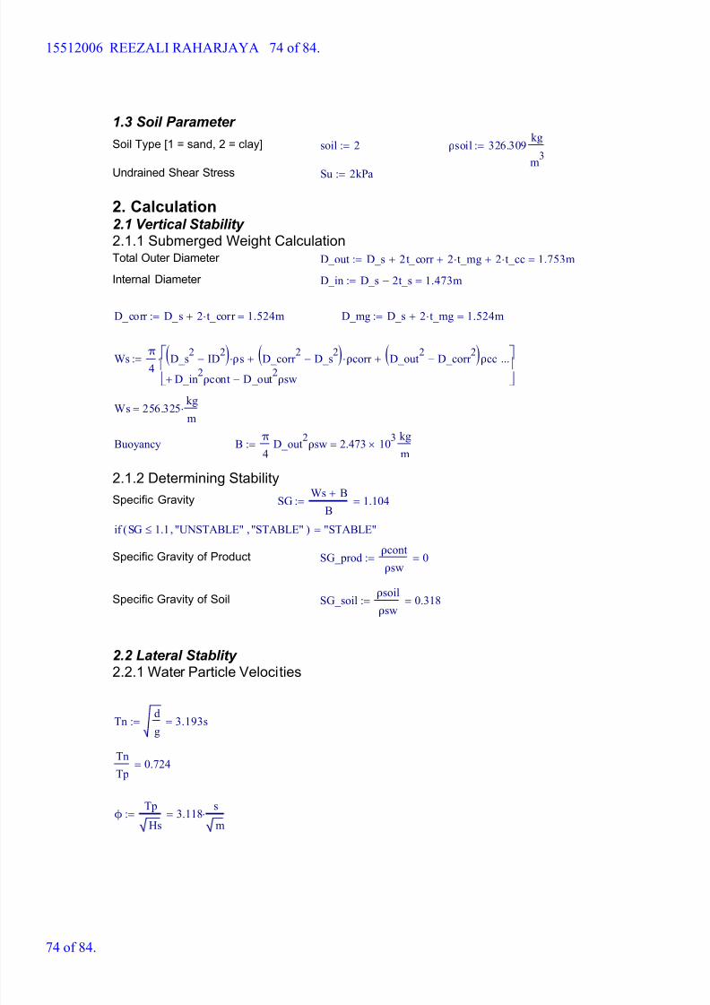
1.3 Soil Parameter
Soil Type [1 = sand, 2 = clay] soil 2:= ρsoil 326.309 kg
m3
:=
Undrained Shear Stress Su 2kPa:=
2. Calculation2.1 Vertical Stability 2.1.1 Submerged Weight CalculationTotal Outer Diameter D_out D_s 2t_corr + 2 t_mg+ 2 t_cc+ 1.753m=:=
Internal Diameter D_in D_s 2t_s- 1.473m=:=
D_corr D_s 2 t_corr + 1.524m=:= D_mg D_s 2 t_mg+ 1.524m=:=
Ws π4
D_s2 ID2-( ) ρs D_corr 2 D_s2-( ) ρcorr + D_out2 D_corr 2-( )ρcc+
D_in2ρcont D_out
2ρsw-+
...
:=
Ws 256.325 kg
m=
Buoyancy B π
4D_out
2ρsw 2.473 10
3
kg
m=:=
2.1.2 Determining Stability
Specific Gravity SG Ws B+
B1.104=:=
if SG 1.1 "UNSTABLE", "STABLE",( ) "STABLE"=
Specific Gravity of Product SG_prod ρcont
ρsw0=:=
Specific Gravity of Soil SG_soil ρsoil
ρsw0.318=:=
2.2 Lateral Stablity 2.2.1 Water Particle Velocities
Tn d
g3.193s=:=
Tn
Tp0.724=
ϕ Tp
Hs3.118
s
m=:=
15512006 REEZALI RAHARJAYA 74 of 84.
74 of 84.
8/15/2019 HW5 2016 15512006
http://slidepdf.com/reader/full/hw5-2016-15512006 75/84
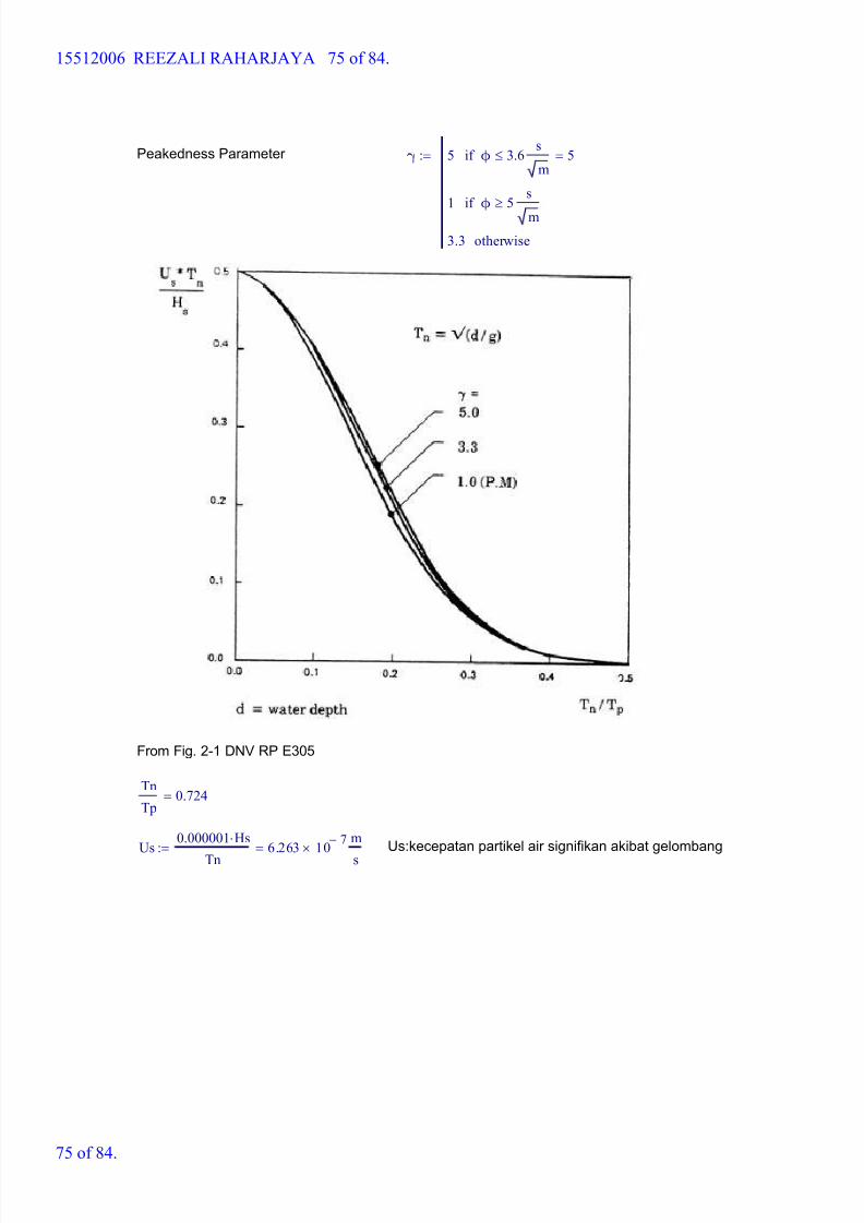
Peakedness Parameter γ 5 ϕ 3.6 s
mif
1 ϕ 5 s
m
if
3.3 otherwise
5=:=
From Fig. 2-1 DNV RP E305
Tn
Tp0.724=
Us 0.000001 Hs
Tn6.263 10
7-
m
s=:= Us:kecepatan partikel air signifikan akibat gelombang
15512006 REEZALI RAHARJAYA 75 of 84.
75 of 84.
8/15/2019 HW5 2016 15512006
http://slidepdf.com/reader/full/hw5-2016-15512006 76/84
From Fig. 2-1 DNV RP E305
Zero Up-Crossing Period Tu 1.4 Tp 6.174s=:=
Table A.1 Soil parameter can be found as
Grain Size d50 0.125mm:=
Roughness Zo 1.04 10
5-m:=
Nikuradse's equivalent sand roughness parameter
Kb 2.5 d50 0.313 mm=:=
Zob Kb
301.042 10
5- m=:=
Using Graph, Fig. 2.2
D_out
Zo1.685 10
5=
Zr Zo
9.615 105=
Ratio average velocity to reference velocity
U_D 1
ln Zr
Zo1+
1 Zo
D_out+
ln D_out
Zo1+
1-
Ur 0.409 m
s=:=
2.2.2 Hydrodinamic Coefficient
15512006 REEZALI RAHARJAYA 76 of 84.
76 of 84.

8/15/2019 HW5 2016 15512006
http://slidepdf.com/reader/full/hw5-2016-15512006 77/84
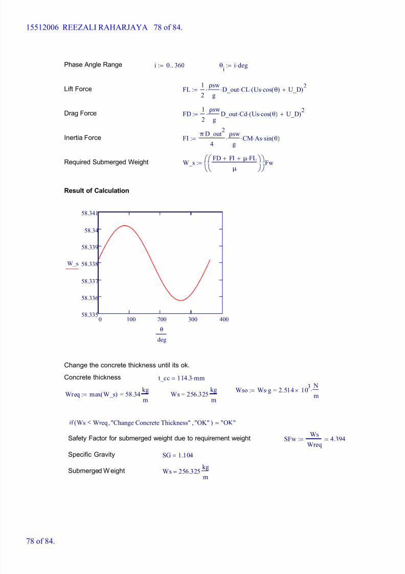
8/15/2019 HW5 2016 15512006
http://slidepdf.com/reader/full/hw5-2016-15512006 78/84
Phase Angle Range i 0 360..:= θi
i deg:=
Lift Force FL 1
2
ρsw
g D_out CL Us cos θ( ) U_D+( )
2:=
Drag Force FD 1
2
ρsw
g D_out Cd Us cos θ( ) U_D+( )
2:=
Inertia Force FI πD_out
2
4
ρsw
g CM As sin θ( ):=
Required Submerged Weight W_s FD FI+ μ FL+
μ
Fw:=
Result of Calculation
0 100 200 300 40058.335
58.336
58.337
58.338
58.339
58.34
58.341
W_s
θ
deg
Change the concrete thickness until its ok.
Concrete thickness t_cc 114.3 mm=
Wso Ws g 2.514 103
N
m=:=
Wreq max W_s( ) 58.34 kg
m
=:= Ws 256.325 kg
m
=
if Ws Wreq "Change Concrete Thickness", "OK",( ) "OK"=
Safety Factor for submerged weight due to requirement weight SFw Ws
Wreq4.394=:=
Specific Gravity SG 1.104=
Submerged Weight Ws 256.325 kg
m=
15512006 REEZALI RAHARJAYA 78 of 84.
78 of 84.

8/15/2019 HW5 2016 15512006
http://slidepdf.com/reader/full/hw5-2016-15512006 79/84
DNV RP305 (Operation) OBS - NPS 60
1. Input Parameter
1.1 Pipeline Design Parameter Outer Diameter D_s 60in 1.524m=:=
Pipe Wall Thickness t_s 1 in:= ID D_s 2 t_s- 1.473m=:=
Corrosion Coating Thickness t_corr 0mm 0 in=:=
Concrete Thickness t_cc 4.5in 0.114m=:=
Pipe Joint Length L 12.2m:=
Steel Pipe Density ρs 490 lb
ft3
:=
Concrete Coating Density ρcc 190 lb
ft3
:=
Corrosion Coating Density ρcorr 940 kg
m3
58.682 lb
ft3
=:=
Density of Sea Water ρsw 1025 kg
m3
63.989 lb
ft3
=:=
Density of Pipeline Content ρcont 35 kg
m3
:=
1.2 Environmental Parameter
Significant Wave Height Hs 3.7m 12.139 ft=:=
Significant Wave Period Ts 5.5s:=
Spectral Peak Period Tp 1.05 Ts 5.775s=:=
Water Depth d 100m 328.084 ft=:=
Current velocity Ur 0.63 m
s2.067
ft
s=:= Zr 10m:=
Kinematic Viscosity of Seawater υ 1.076 10 5-
ft
2
s:=
Corrosion Allowance ca 3mm:=
Marine Growth Thickness t_mg 0mm:=
Marine Growth Density ρmg 1400 kg
m3
:=
15512006 REEZALI RAHARJAYA 79 of 84.
79 of 84.
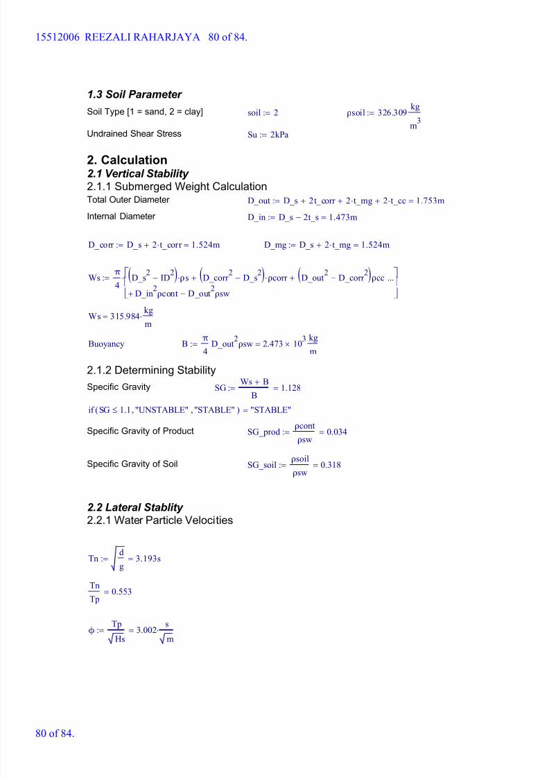
8/15/2019 HW5 2016 15512006
http://slidepdf.com/reader/full/hw5-2016-15512006 80/84
1.3 Soil Parameter
Soil Type [1 = sand, 2 = clay] soil 2:= ρsoil 326.309 kg
m3
:=
Undrained Shear Stress Su 2kPa:=
2. Calculation2.1 Vertical Stability 2.1.1 Submerged Weight CalculationTotal Outer Diameter D_out D_s 2t_corr + 2 t_mg+ 2 t_cc+ 1.753m=:=
Internal Diameter D_in D_s 2t_s- 1.473m=:=
D_corr D_s 2 t_corr + 1.524m=:= D_mg D_s 2 t_mg+ 1.524m=:=
Ws π4
D_s2 ID2-( ) ρs D_corr 2 D_s2-( ) ρcorr + D_out2 D_corr 2-( )ρcc+
D_in2
ρcont D_out2
ρsw-+
...
:=
Ws 315.984 kg
m=
Buoyancy B π
4D_out
2ρsw 2.473 10
3
kg
m=:=
2.1.2 Determining Stability
Specific Gravity SG Ws B+
B1.128=:=
if SG 1.1 "UNSTABLE", "STABLE",( ) "STABLE"=
Specific Gravity of Product SG_prod ρcont
ρsw0.034=:=
Specific Gravity of Soil SG_soil ρsoil
ρsw0.318=:=
2.2 Lateral Stablity 2.2.1 Water Particle Velocities
Tn d
g3.193s=:=
Tn
Tp0.553=
ϕ Tp
Hs3.002
s
m=:=
15512006 REEZALI RAHARJAYA 80 of 84.
80 of 84.

8/15/2019 HW5 2016 15512006
http://slidepdf.com/reader/full/hw5-2016-15512006 81/84
Peakedness Parameter γ 5 ϕ 3.6 s
mif
1 ϕ 5 s
m
if
3.3 otherwise
5=:=
From Fig. 2-1 DNV RP E305
Tn
Tp0.553=
Us 0.000001 Hs
Tn1.159 10
6-
m
s=:= Us:kecepatan partikel air signifikan akibat gelombang
15512006 REEZALI RAHARJAYA 81 of 84.
81 of 84.

8/15/2019 HW5 2016 15512006
http://slidepdf.com/reader/full/hw5-2016-15512006 82/84
From Fig. 2-1 DNV RP E305
Zero Up-Crossing Period Tu 1.4 Tp 8.085s=:=
Table A.1 Soil parameter can be found as
Grain Size d50 0.125mm:=
Roughness Zo 1.04 10
5-m:=
Nikuradse's equivalent sand roughness parameter
Kb 2.5 d50 0.313 mm=:=
Zob Kb
301.042 10
5- m=:=
Using Graph, Fig. 2.2
D_out
Zo1.685 10
5=
Zr Zo
9.615 105=
Ratio average velocity to reference velocity
U_D 1
ln Zr
Zo1+
1 Zo
D_out+
ln D_out
Zo1+
1-
Ur 0.505 m
s=:=
2.2.2 Hydrodinamic Coefficient
15512006 REEZALI RAHARJAYA 82 of 84.
82 of 84.
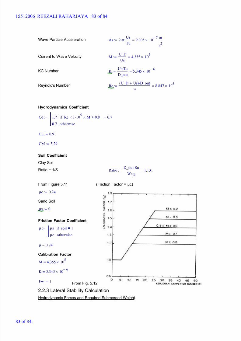
8/15/2019 HW5 2016 15512006
http://slidepdf.com/reader/full/hw5-2016-15512006 83/84
Wave Particle Acceleration As 2 π Us
Tu9.005 10
7-
m
s2
=:=
Current to Wave Velocity M U_D
Us4.355 10
5=:=
KC Number K Us Tu
D_out5.345 10
6-=:=
Reynold's Number Re U_D Us+( ) D_out
υ8.847 10
5=:=
Hydrodynamics Coefficient
Cd 1.2 Re 3 105
< M 0.8if
0.7 otherwise
0.7=:=
CL 0.9:=
CM 3.29:=
Soil Coefficient
Clay Soil
Ratio = 1/S Ratio D_out Su
Ws g 1.131=:=
From Figure 5.11 (Friction Factor = μc)
μc 0.24:=
Sand Soil
μs 0:=
Friction Factor Coefficient
μ μs soil 1=if
μc otherwise
:=
μ 0.24=
Calibration Factor
M 4.355 105
=
K 5.345 10 6-
=
Fw 1:=From Fig. 5.12
2.2.3 Lateral Stability Calculation
Hydrodynamic Forces and Required Submerged Weight
15512006 REEZALI RAHARJAYA 83 of 84.
83 of 84.
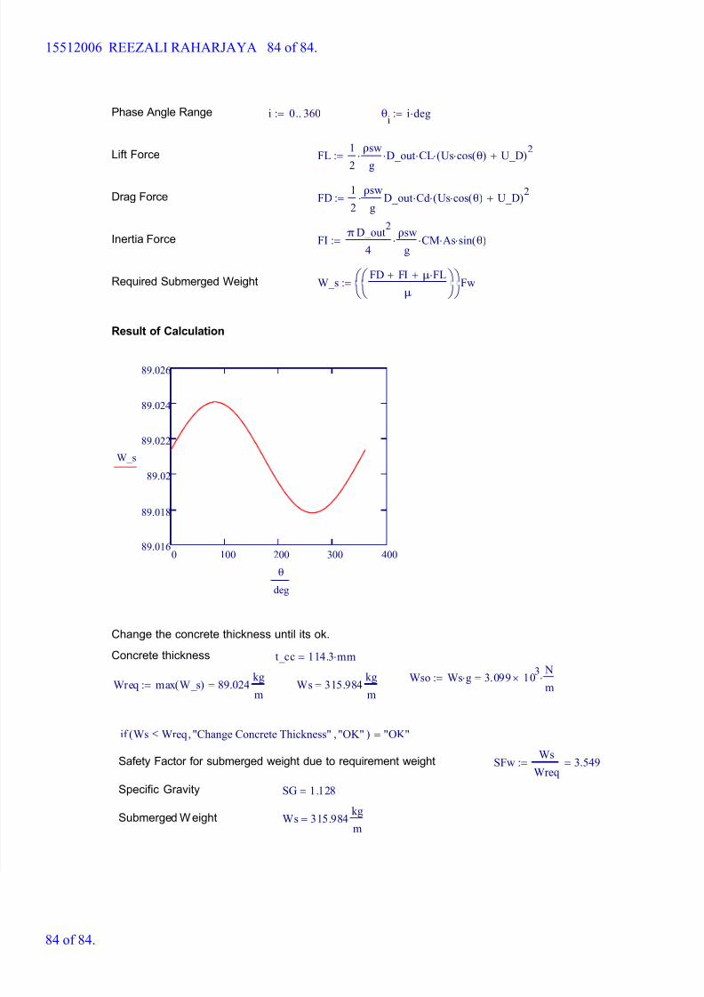
8/15/2019 HW5 2016 15512006
http://slidepdf.com/reader/full/hw5-2016-15512006 84/84
Phase Angle Range i 0 360..:= θi
i deg:=
Lift Force FL 1
2
ρsw
g D_out CL Us cos θ( ) U_D+( )
2:=
Drag Force FD 1
2
ρsw
g D_out Cd Us cos θ( ) U_D+( )
2:=
Inertia Force FI π D_out
2
4
ρsw
g CM As sin θ( ):=
Required Submerged Weight W_s FD FI+ μ FL+
μ
Fw:=
Result of Calculation
0 100 200 300 40089.016
89.018
89.02
89.022
89.024
89.026
W_s
θ
deg
Change the concrete thickness until its ok.
Concrete thickness t_cc 114.3 mm=
Wso Ws g 3.099 103
N
m=:=
Wreq max W_s( ) 89.024 kg
m
=:= Ws 315.984 kg
m
=
if Ws Wreq "Change Concrete Thickness" "OK"( ) "OK"
15512006 REEZALI RAHARJAYA 84 of 84.