Embed Size (px)
Citation preview
FPGA-BASED REAL-TIME GPS RECEIVER
A Design Project ReportPresented to the Engineering Division of the Graduate School
of Cornell Universityin Partial Fulfillment of the Requirements for the Degree of
Master of Engineering (Electrical)
byAdam M. Shapiro
Project Advisor: Bruce R. Land
Degree Date: January, 2010
Abstract
Master of Electrical Engineering Program
Cornell University
Design Project Report
Project Title: FPGA-based Real-time GPS Receiver
Author: Adam M. Shapiro
Abstract:
A survey of the available open-source resources in the field of satellite navigation systemsreveals that there is a shortage of robust, easily reconfigurable code. Most existing designsare either intended only for a specific use and therefore too difficult to modify for general-purpose release, or commercially sold and not openly available. With this situation in mind,we are currently working with in collaboration with the Cornell GNSS Research Group todevelop and build a mobile FPGA-based GPS receiver. Our intent is to create a generalpurpose receiver which is easily modifiable, highly modular, and completely open-source.
The design consists of two major components, implemented on separate Altera Cyclone IIFPGAs in Verilog. The primary component is a hardware GPS receiver, capable of receiving,tracking, and processing multiple satellite transmissions of the L1 civilian GPS signal in realtime. The secondary component is a combined navigation controller and graphics processingunit designed to calculate a navigation solution in real-time and provide a human-readablegraphical interface. Once completed, this freely available general purpose receiver shouldprove useful to the Cornell GNSS Research Group as well as the satellite navigation researchcommunity as a whole.
Report Approved by
Project Advisor: Date:
1
Executive Summary
This project involved the design and development of an open source GPS receiver on anFPGA. The receiver was developed in such a way as to be completely customizable, allowinga user to easily reconfigure it for most applications involving currently-available civilianGPS technology. In addition, the receiver was designed with further development in mindby standardizing interfaces so that new algorithms, designs, and hardware modules could bequickly integrated into the existing platform.
The GPS receiver was developed and tested in the Verilog hardware description language foran Altera Cyclone II FPGA. The hardware was modeled and simulated using a MATLAB re-ceiver emulator, and the results were then compared with the those of the hardware receiver.Initial testing has been successful, and has shown much promise. The hardware is capable ofacquiring and tracking a number of GPS satellites in parallel in a variety of environmentalconditions. Hardware design optimization has made the receiver resource-efficient enough togreatly exceed initial expectations of tracking capabilities, particularly the number satellitesthat can be tracked simultaneously. Further development will provide data extraction andsatellite observable reporting functionality, allowing a user to navigate using the receiver inreal-time.
In addition to the development of the hardware receiver, a significant portion of this projectinvolved the creation of a system for quickly developing large-scale embedded systems projects.A methodology and set of guidelines were developed that aid in the quick production of clean,understandable, functional code. The guidelines set forth rules for hardware development,coding style, and testing methods, all of which aid the system integration process and greatlyreduce development time. A set of software tools was developed which enable quick gen-eration of reusable, reconfigurable Verilog hardware. The tools have been tested in thedevelopment of the hardware receiver, as well as in external projects, and have proven to bean extremely useful and valuable resource.
All of the hardware, software, and tools developed for this project have been released to thepublic domain under the GNU General Public License, version 2.
2
Contents
1 Introduction 5
1.1 Design Alternatives . . . . . . . . . . . . . . . . . . . . . . . . . . . . . . . . 5
2 The Global Positioning System 6
2.1 GPS Signal Description . . . . . . . . . . . . . . . . . . . . . . . . . . . . . . 6
2.2 Satellite Acquisition . . . . . . . . . . . . . . . . . . . . . . . . . . . . . . . 6
2.3 Signal Tracking . . . . . . . . . . . . . . . . . . . . . . . . . . . . . . . . . . 8
2.4 Data . . . . . . . . . . . . . . . . . . . . . . . . . . . . . . . . . . . . . . . . 8
2.5 Observables . . . . . . . . . . . . . . . . . . . . . . . . . . . . . . . . . . . . 9
3 Implementation 10
3.1 Receiver Overview . . . . . . . . . . . . . . . . . . . . . . . . . . . . . . . . 11
3.2 Channels . . . . . . . . . . . . . . . . . . . . . . . . . . . . . . . . . . . . . . 12
3.3 Direct Digital Synthesis . . . . . . . . . . . . . . . . . . . . . . . . . . . . . 13
3.4 Acquisition Units . . . . . . . . . . . . . . . . . . . . . . . . . . . . . . . . . 14
3.5 Tracking Loops . . . . . . . . . . . . . . . . . . . . . . . . . . . . . . . . . . 16
3.5.1 Square Root . . . . . . . . . . . . . . . . . . . . . . . . . . . . . . . . 17
3.5.2 Delay-Locked Loop (DLL) . . . . . . . . . . . . . . . . . . . . . . . . 17
3.5.3 Frequency-Locked Loop (FLL) . . . . . . . . . . . . . . . . . . . . . . 20
3.5.4 Phase-Locked Loop (PLL) . . . . . . . . . . . . . . . . . . . . . . . . 21
3.6 Data Extraction . . . . . . . . . . . . . . . . . . . . . . . . . . . . . . . . . . 21
3.7 Lock Indicators . . . . . . . . . . . . . . . . . . . . . . . . . . . . . . . . . . 22
3.8 Observables Extraction . . . . . . . . . . . . . . . . . . . . . . . . . . . . . . 23
3.9 Clock Domain Synchronization . . . . . . . . . . . . . . . . . . . . . . . . . 23
4 Tools and Testing 24
4.1 Verilog Defines Parser . . . . . . . . . . . . . . . . . . . . . . . . . . . . . . 26
4.2 Verilog Preprocessor . . . . . . . . . . . . . . . . . . . . . . . . . . . . . . . 26
4.3 High-Speed Ethernet Data Feed . . . . . . . . . . . . . . . . . . . . . . . . . 27
4.4 Data Generation . . . . . . . . . . . . . . . . . . . . . . . . . . . . . . . . . 28
3

4.4.1 Fixed-Point Implementation . . . . . . . . . . . . . . . . . . . . . . . 28
4.5 MATLAB Software Testbench . . . . . . . . . . . . . . . . . . . . . . . . . . 29
5 Results 29
5.1 Hardware . . . . . . . . . . . . . . . . . . . . . . . . . . . . . . . . . . . . . 32
5.2 Issues . . . . . . . . . . . . . . . . . . . . . . . . . . . . . . . . . . . . . . . 32
6 Future Goals 33
7 Acknowledgments 34
8 Appendix 34
4
1 Introduction
The expansion of the open-source software community has prompted many researchers tolook for publicly available solutions before turning to more costly alternatives, often withremarkable success. However, the satellite navigation community seems to suffer from adearth of quality open-source code. This is in part due to the fact that most satellitenavigation research is carried out by government or commercial organizations, which areoften reluctant to release design data under public license. In an attempt to make a valuablecontribution to the open-source resources available to the Global Positioning System (GPS)community, we have been working with the Cornell Global Navigation Satellite Systems(GNSS) research group to develop and build a mobile GPS receiver.
Commercial and academic GPS receivers are often designed in software for ease of modi-fication and production. Writing software affords a number of benefits, including ease ofdebugging, modularity, and expandability. It is often considerably easier to prototype asystem in software, either on a CPU or a DSP, than it is to develop an equivalent system inhardware. That being said, satellite tracking is a largely parallelizable process, and the serialnature of software makes it difficult to easily take advantage of this fact. One of the primarygoals of this project is to design a modular, parallel architecture for GPS signal tracking inhardware, while still maintaining much of the modularity and expandability attributed tosoftware. At the same time, we have developed a system of design and set of tools to easethe development of such large-scale hardware systems in the future.
Presented here is a discussion of the design and development of the hardware GPS receiver de-veloped for this project. Basic concepts of GPS navigation and signal tracking are reviewed,followed by an enumeration of several issues and challenges involved in such a design, as wellas the strategies developed to address those issues. Finally, preliminary receiver results andfuture goals for the project are discussed, as well as a description of the tools and proceduresdeveloped to aid in the production of such a complex system on an FPGA in Verilog.
1.1 Design Alternatives
The initial attempt at building this receiver produced tracking channels in which hardwarewas dedicated to a single satellite at a time. Additionally, the multipliers required to cal-culate vector magnitudes were contained within each channel instead of within the trackingloops, further reducing the amount of shared resources. This design, while fully functional,was extremely inefficient. A single channel, capable of tracking only one satellite, took ap-proximately 3,500 FPGA logic elements (where each element consists of a single flip-flop, a4-input logic lookup table, and an arithmetic carry chain) and a number of hardware multi-pliers to implement. This design severely limited the extendibility of the receiver. The largenumber of logic elements dedicated to each channel meant that the receiver would only beable to support a maximum 8 parallel channels.
An original project design iteration involved including hardware for a navigation controllerand graphical interface on the same FPGA as the receiver. This plan was quickly changed
5
however, in favor of a data and observables packaging system. Continuing the generic designmethodology, by packaging the data into a standardized format, the receiver is able to beconnected to any compliant navigation controller, or directly connected to a computer, foruse.
2 The Global Positioning System
2.1 GPS Signal Description
Satellite navigation systems work by triangulating a user’s location from known-locationreference transmitters. In the case of GPS, a constellation of 32 satellites orbits the Earth ina Medium Earth Orbit (MEO), with a height range of approximately 20,000 km to 26,000 km.[5] Each satellite transmits a data message, providing a receiver with orbital parameters thatcan then be used to determine the satellite location. Once the locations are known for eachof the available satellites in view, the receiver can then determine its location by calculatingdistances to each satellite from the time-of-flight of the data bits for that satellite’s message.
The currently-available civilian GPS signal, called the Coarse Acquisition (C/A) code, isbroadcast by each satellite in the constellation on the GPS L1 frequency (1575.42 MHz).This signal contains a data message with the broadcasting satellite’s orbital parameters(ephemerides), an atmospheric correction model, and a set of coarse satellite positioningparameters for all satellites, known as the almanac. The broadcast signals are encodedwith a Code-Division Multiple Access (CDMA) scheme such that all satellites can broadcastsimultaneously on the same frequency. The signal is then mixed with the L1 carrier frequencyand broadcast.
The CDMA encoding scheme uses pseudorandom binary sequences known as Gold codes.Gold codes are maximum-length sequences with very good cross-correlation characteristics,which allow for easy signal separation of individual signals by a receiver. A data streamencoded with a given code (referred to by its pseudorandom number code, or PRN code)can be transmitted at the same time as another, and later recovered by correlating it withthat same code. The codes used for the L1 C/A code are 1023 bits long and transmit at arate of 1.023 MHz. Code bits are referred to as chips in order to distinguish them from databits, as the code bits carry no useful information.
2.2 Satellite Acquisition
Acquisition is the process by which the receiver determines which satellites are in view suchthat it can track them and begin to navigate. To track a satellite’s transmitted signal, areceiver must remove both the carrier frequency and the PRN code from the signal, so thatthe remaining signal only contains the transmitted data bits (plus noise). There are thereforetwo pieces of information that a receiver needs to know in order to track a given satellite:the carrier frequency and the code position, as explained below.
6
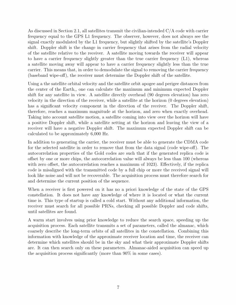
As discussed in Section 2.1, all satellites transmit the civilian-intended C/A code with carrierfrequency equal to the GPS L1 frequency. The observer, however, does not always see thesignal exactly modulated by the L1 frequency, but slightly shifted by the satellite’s Dopplershift. Doppler shift is the change in carrier frequency that arises from the radial velocityof the satellite relative to the receiver. A satellite moving towards the receiver will appearto have a carrier frequency slightly greater than the true carrier frequency (L1), whereasa satellite moving away will appear to have a carrier frequency slightly less than the truecarrier. This means that, in order to demodulate the signal to removing the carrier frequency(baseband wipe-off), the receiver must determine the Doppler shift of the satellite.
Using a the satellite orbital velocity and the satellite orbit apogee and perigee distances fromthe center of the Earth,, one can calculate the maximum and minimum expected Dopplershift for any satellite in view. A satellite directly overhead (90 degrees elevation) has zerovelocity in the direction of the receiver, while a satellite at the horizon (0 degrees elevation)has a significant velocity component in the direction of the receiver. The Doppler shift,therefore, reaches a maximum magnitude at the horizon, and zero when exactly overhead.Taking into account satellite motion, a satellite coming into view over the horizon will havea positive Doppler shift, while a satellite setting at the horizon and leaving the view of areceiver will have a negative Doppler shift. The maximum expected Doppler shift can becalculated to be approximately 6,000 Hz.
In addition to generating the carrier, the receiver must be able to generate the CDMA codefor the selected satellite in order to remove that from the data signal (code wipe-off). Theautocorrelation properties of the Gold codes are such that if the generated replica code isoffset by one or more chips, the autocorrelation value will always be less than 100 (whereaswith zero offset, the autocorrelation reaches a maximum of 1023). Effectively, if the replicacode is misaligned with the transmitted code by a full chip or more the received signal willlook like noise and will not be recoverable. The acquisition process must therefore search forand determine the current position of the sequence.
When a receiver is first powered on it has no a priori knowledge of the state of the GPSconstellation. It does not have any knowledge of where it is located or what the currenttime is. This type of startup is called a cold start. Without any additional information, thereceiver must search for all possible PRNs, checking all possible Doppler and code shifts,until satellites are found.
A warm start involves using prior knowledge to reduce the search space, speeding up theacquisition process. Each satellite transmits a set of parameters, called the almanac, whichcoarsely describe the long-term orbits of all satellites in the constellation. Combining thisinformation with knowledge of the approximate receiver location and time, the receiver candetermine which satellites should be in the sky and what their approximate Doppler shiftsare. It can then search only on these parameters. Almanac-aided acquisition can speed upthe acquisition process significantly (more than 90% in some cases).
7
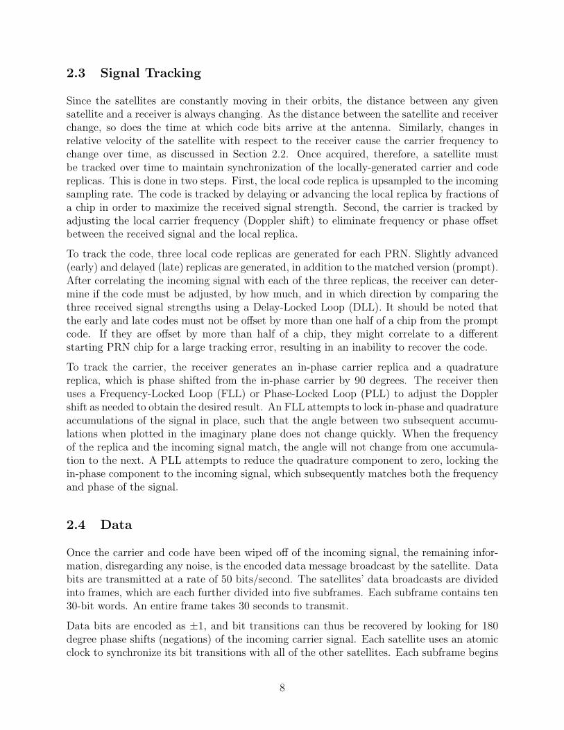
2.3 Signal Tracking
Since the satellites are constantly moving in their orbits, the distance between any givensatellite and a receiver is always changing. As the distance between the satellite and receiverchange, so does the time at which code bits arrive at the antenna. Similarly, changes inrelative velocity of the satellite with respect to the receiver cause the carrier frequency tochange over time, as discussed in Section 2.2. Once acquired, therefore, a satellite mustbe tracked over time to maintain synchronization of the locally-generated carrier and codereplicas. This is done in two steps. First, the local code replica is upsampled to the incomingsampling rate. The code is tracked by delaying or advancing the local replica by fractions ofa chip in order to maximize the received signal strength. Second, the carrier is tracked byadjusting the local carrier frequency (Doppler shift) to eliminate frequency or phase offsetbetween the received signal and the local replica.
To track the code, three local code replicas are generated for each PRN. Slightly advanced(early) and delayed (late) replicas are generated, in addition to the matched version (prompt).After correlating the incoming signal with each of the three replicas, the receiver can deter-mine if the code must be adjusted, by how much, and in which direction by comparing thethree received signal strengths using a Delay-Locked Loop (DLL). It should be noted thatthe early and late codes must not be offset by more than one half of a chip from the promptcode. If they are offset by more than half of a chip, they might correlate to a differentstarting PRN chip for a large tracking error, resulting in an inability to recover the code.
To track the carrier, the receiver generates an in-phase carrier replica and a quadraturereplica, which is phase shifted from the in-phase carrier by 90 degrees. The receiver thenuses a Frequency-Locked Loop (FLL) or Phase-Locked Loop (PLL) to adjust the Dopplershift as needed to obtain the desired result. An FLL attempts to lock in-phase and quadratureaccumulations of the signal in place, such that the angle between two subsequent accumu-lations when plotted in the imaginary plane does not change quickly. When the frequencyof the replica and the incoming signal match, the angle will not change from one accumula-tion to the next. A PLL attempts to reduce the quadrature component to zero, locking thein-phase component to the incoming signal, which subsequently matches both the frequencyand phase of the signal.
2.4 Data
Once the carrier and code have been wiped off of the incoming signal, the remaining infor-mation, disregarding any noise, is the encoded data message broadcast by the satellite. Databits are transmitted at a rate of 50 bits/second. The satellites’ data broadcasts are dividedinto frames, which are each further divided into five subframes. Each subframe contains ten30-bit words. An entire frame takes 30 seconds to transmit.
Data bits are encoded as ±1, and bit transitions can thus be recovered by looking for 180degree phase shifts (negations) of the incoming carrier signal. Each satellite uses an atomicclock to synchronize its bit transitions with all of the other satellites. Each subframe begins
8
with a 30-bit telemetry word, which contains a fixed 22-bit preamble, followed by a telemetrymessage and accompanying parity bits. [5] A receiver can use the preamble to locate thestart of a subframe prior to decoding the data message.
The subframes from a given satellite provide ephemeris data required to locate the satellite’sorbital position, satellite constellation health information, atmospheric modeling parametersused to correct for positioning errors introduced by ionospheric and tropospheric delays, andan almanac of long-term, coarse satellite orbital parameters for the entire constellation.
2.5 Observables
Navigation using GPS involves triangulating the receiver location in three dimensions relativeto the positions of the satellites. To do this, the receiver needs to know how far it is from eachsatellite used for navigation. Additionally, it must be able to determine to high precisionwhere the satellites are in their orbits, which requires precise knowledge of the current time.While there are only three positional degrees of freedom that must be resolved to locatea receiver, the unknown mismatch between the receiver and satellite clocks adds a fourthunknown that must also be solved in order to navigate. A receiver must therefore tracka minimum of four satellites to navigate without additional assistance. Once a signal istracked, there are three observable parameters that the receiver can extract that provide itwith this information.
The first observable, pseudorange, is perhaps the most intuitive of the three. The range toa given satellite is given by the time from transmission of a given bit to reception of thatbit, multiplied by the speed of light. Pseudorange is the distance to a satellite measured inthis fashion, plus or minus some additional error sources. Since the transmission time is notknown by the receiver, this value cannot be directly measured. Because the bit transitionsfor all satellites occur at the same time (see Section 2.4), however, the distance of one satelliteto the receiver can be measured relative to another satellite. By selecting one satellite as areference point, the relative distances to all other satellites can be measured. The differencebetween the relative ranges and the true ranges is simply the range to the reference satellite.This unknown distance is the first difference between pseudorange and true range, and isusually thought of as a receiver clock bias.
Next, though the satellites have highly-precise clocks, each has a slight drift which addsadditional error to the range calculation. This drift is tracked closely by the GPS controlsegment, modeled as a quadratic error, and broadcast as part of the ephemeris data to thereceiever.
If the transmitted signals travelled through vacuum to the receiver, the measured transmis-sion times would exactly equal the distances to the satellites given the speed of light. Thesignals do not travel through vacuum, however, and are delayed by any medium they passthrough including the ionosphere and troposphere, as well as any ground-based objects theymay meet on the way to the receiver. An atmospheric model, which can be used to correctfor some signal delay in order to improve navigation accuracy, is broadcast as part of thedata message send with the C/A code.
9
Adding all of these error sources together results in the receiver-perceived distance, pseudo-range, as follows
P S = ρS + c(δS − δR) + εS (1)
where P S is the pseudorange for satellite S, ρS is the true range to satellite S, δS is satel-lite S’s clock offset, δR is the receiver clock error (including the unknown reference satelliterange), and εS is additional error introduced by atmospheric propagation, multipath inter-ference, and other sources. Note that δR is common to all satellites, while εS is satellite-depedent. Because pseudorange is defined by the signal data bit transitions, it is only asaccurate as the upsampled code chipping rate (sampling rate) multiplied by the speed oflight.
The next observable, Doppler shift, is the most easily-found observable. It is tracked anddirectly reported by the carrier tracking loops. Doppler shift represents the velocity of theradial receiver with respect to the satellite. The measured Doppler shift includes this valueand error terms due to the clock drift rates of both the satellite and the receiver. TheDoppler shift, measured in Hz, is given by
fD =fL1
1 + δ̇S
[−ρ̂T (~vS − ~v) + cδ̇Rc+ ρ̂T (~vS − ~v)
− δ̇S
](2)
where fD and fL1 are the Doppler shift and the L1 frequency of 1575.42MHz respectively,ρ̂ is the unit vector to satellite S from the receiver location in Earth-Centered, Earth-Fixed(ECEF) coordinates, ~vS is the satellite velocity vector in ECEF, ~v receiver velocity in ECEF,and c is the speed of light in meters per second. δ̇S and δ̇R are the derivatives of the satelliteand receiver clock offsets, respectively.
The final observable, carrier phase, represents the range to the satellite defined by the num-ber of carrier cycles between it and the receiver. Using a PLL, the receiver can keep trackof the number of carrier cycles that elapse during a given accumulation period. The rangeto the satellite can then be determined with an accuracy on the order of the L1 wavelength(approximately 0.19 m). However, because phase range is a relative measurement (the re-ceiver measures changes in phase, not total phase), the true range to the satellite is unknowninitially. Resolving the initial number of cycles between the receiver and the satellite is anissue known as the integer ambiguity problem, and is an active topic of research.
Methods for determining the receiver location and velocity, as well as the current time, arenot discussed in this paper. Focus will instead be placed on satellite acquisition and tracking.
3 Implementation
This section discusses the implementation details of the hardware receiver. The receiverhas been developed in conjunction with Cornell Electrical and Computer Engineering de-
10
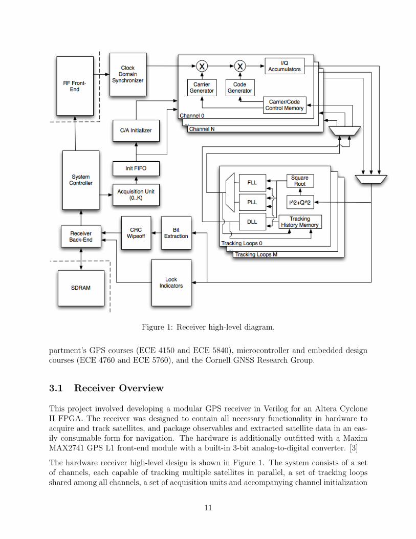
Figure 1: Receiver high-level diagram.
partment’s GPS courses (ECE 4150 and ECE 5840), microcontroller and embedded designcourses (ECE 4760 and ECE 5760), and the Cornell GNSS Research Group.
3.1 Receiver Overview
This project involved developing a modular GPS receiver in Verilog for an Altera CycloneII FPGA. The receiver was designed to contain all necessary functionality in hardware toacquire and track satellites, and package observables and extracted satellite data in an eas-ily consumable form for navigation. The hardware is additionally outfitted with a MaximMAX2741 GPS L1 front-end module with a built-in 3-bit analog-to-digital converter. [3]
The hardware receiver high-level design is shown in Figure 1. The system consists of a setof channels, each capable of tracking multiple satellites in parallel, a set of tracking loopsshared among all channels, a set of acquisition units and accompanying channel initialization
11
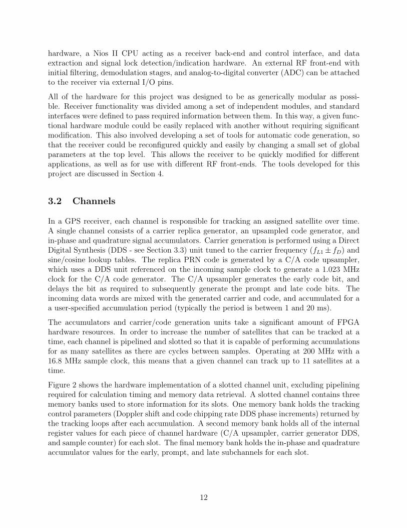
hardware, a Nios II CPU acting as a receiver back-end and control interface, and dataextraction and signal lock detection/indication hardware. An external RF front-end withinitial filtering, demodulation stages, and analog-to-digital converter (ADC) can be attachedto the receiver via external I/O pins.
All of the hardware for this project was designed to be as generically modular as possi-ble. Receiver functionality was divided among a set of independent modules, and standardinterfaces were defined to pass required information between them. In this way, a given func-tional hardware module could be easily replaced with another without requiring significantmodification. This also involved developing a set of tools for automatic code generation, sothat the receiver could be reconfigured quickly and easily by changing a small set of globalparameters at the top level. This allows the receiver to be quickly modified for differentapplications, as well as for use with different RF front-ends. The tools developed for thisproject are discussed in Section 4.
3.2 Channels
In a GPS receiver, each channel is responsible for tracking an assigned satellite over time.A single channel consists of a carrier replica generator, an upsampled code generator, andin-phase and quadrature signal accumulators. Carrier generation is performed using a DirectDigital Synthesis (DDS - see Section 3.3) unit tuned to the carrier frequency (fL1± fD) andsine/cosine lookup tables. The replica PRN code is generated by a C/A code upsampler,which uses a DDS unit referenced on the incoming sample clock to generate a 1.023 MHzclock for the C/A code generator. The C/A upsampler generates the early code bit, anddelays the bit as required to subsequently generate the prompt and late code bits. Theincoming data words are mixed with the generated carrier and code, and accumulated for aa user-specified accumulation period (typically the period is between 1 and 20 ms).
The accumulators and carrier/code generation units take a significant amount of FPGAhardware resources. In order to increase the number of satellites that can be tracked at atime, each channel is pipelined and slotted so that it is capable of performing accumulationsfor as many satellites as there are cycles between samples. Operating at 200 MHz with a16.8 MHz sample clock, this means that a given channel can track up to 11 satellites at atime.
Figure 2 shows the hardware implementation of a slotted channel unit, excluding pipeliningrequired for calculation timing and memory data retrieval. A slotted channel contains threememory banks used to store information for its slots. One memory bank holds the trackingcontrol parameters (Doppler shift and code chipping rate DDS phase increments) returned bythe tracking loops after each accumulation. A second memory bank holds all of the internalregister values for each piece of channel hardware (C/A upsampler, carrier generator DDS,and sample counter) for each slot. The final memory bank holds the in-phase and quadratureaccumulator values for the early, prompt, and late subchannels for each slot.
12
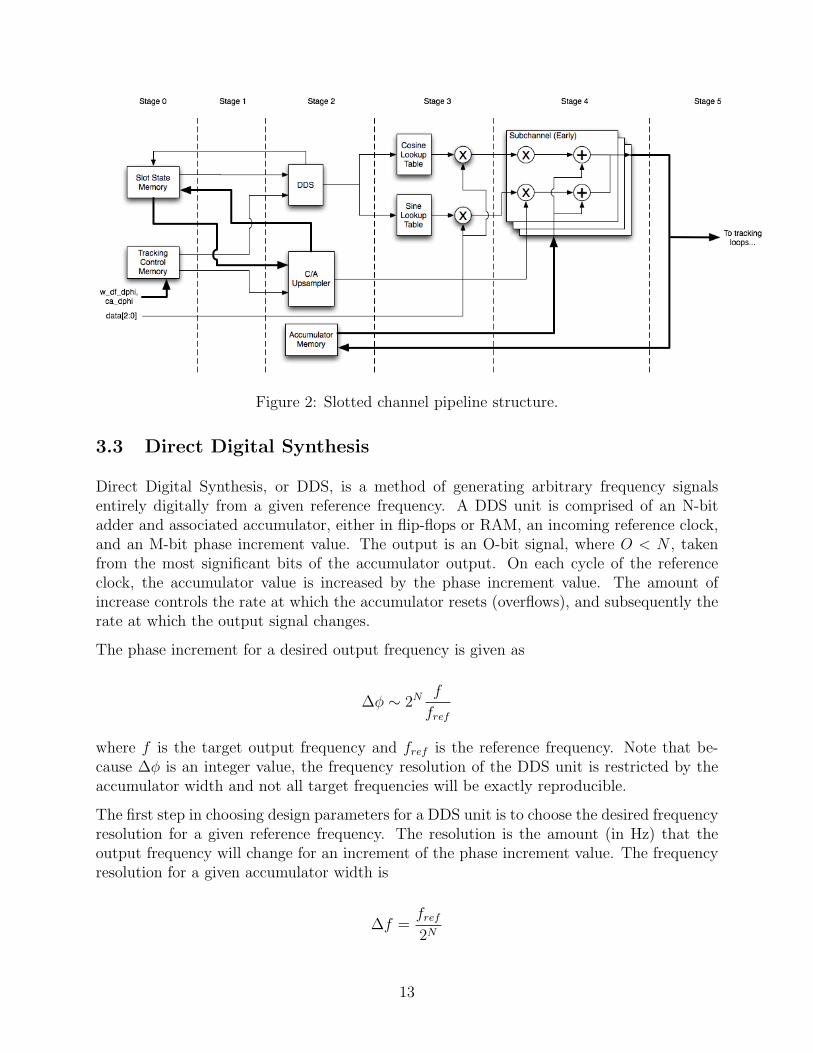
Figure 2: Slotted channel pipeline structure.
3.3 Direct Digital Synthesis
Direct Digital Synthesis, or DDS, is a method of generating arbitrary frequency signalsentirely digitally from a given reference frequency. A DDS unit is comprised of an N-bitadder and associated accumulator, either in flip-flops or RAM, an incoming reference clock,and an M-bit phase increment value. The output is an O-bit signal, where O < N , takenfrom the most significant bits of the accumulator output. On each cycle of the referenceclock, the accumulator value is increased by the phase increment value. The amount ofincrease controls the rate at which the accumulator resets (overflows), and subsequently therate at which the output signal changes.
The phase increment for a desired output frequency is given as
∆φ ∼ 2N f
fref
where f is the target output frequency and fref is the reference frequency. Note that be-cause ∆φ is an integer value, the frequency resolution of the DDS unit is restricted by theaccumulator width and not all target frequencies will be exactly reproducible.
The first step in choosing design parameters for a DDS unit is to choose the desired frequencyresolution for a given reference frequency. The resolution is the amount (in Hz) that theoutput frequency will change for an increment of the phase increment value. The frequencyresolution for a given accumulator width is
∆f =fref
2N
13
and so, for a desired frequency resolution the required accumulator width is
N =
⌈log2
(fref
∆fres
)⌉Next, the maximum phase increment value can be determined from the maximum outputfrequency necessary for the DDS to produce.
∆φmax = 2M fmax
fref
Finally, the required phase increment width is
M = dlog2 (∆φmax)e
3.4 Acquisition Units
Each acquisition unit is designed to perform a brute-force acquisition for a specified PRN.Each unit is outfitted with a C/A code generator, an acquisition controller, and a user-specifiable number of accumulation units. Each accumulation unit is connected to a dedi-cated carrier generator DDS unit and accompanying demodulation hardware.
When performing a search, the acquisition controller assigns Doppler shift bins to each accu-mulation unit, where the bin spacing is specified by the user at compile time. Accumulationsare then performed by demodulating the signal using the assigned Doppler shift, and cor-relating it with the local code replica for all possible code shifts. The accumulation vectormagnitude (see Section 3.5) is then computed, and the peak value is stored along with itscorresponding Doppler and code shifts. Once all Doppler and code shifts have been tested,the peak magnitude is compared to a predefined carrier-to-noise threshold to determine ifa satellite has been located. A second threshold is defined which enables the accumulationunit to terminate prematurely if a local maximum peak has been located above a certaincarrier-to-noise ratio.
LSingle Shift = fsTC/A
LSingle Bin = (fsTAcc)LSingle Shift = f 2s TAccTC/A
LFull PRN Search =2fD,max
∆fBin
LSingle Bin =2fD,maxf
2s TAccTC/A
∆fBin
LAcquisitionLength =LFull PRN Search
NAccumulators
=2fD,maxf
2s TAccTC/A
NAccumulators∆fBin
(3)
The total length of time required to perform a brute-force acquisition for a single satellitedepends on the size of the Doppler shift search space, the frequency spacing of the Doppler
14
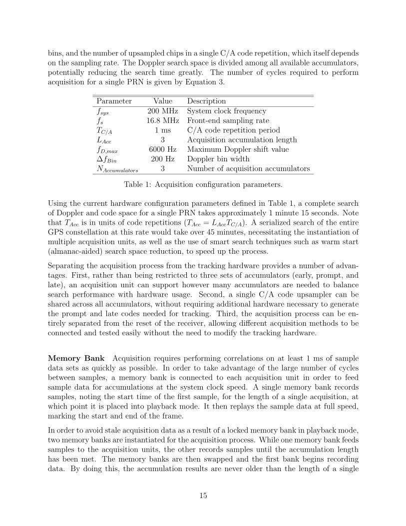
bins, and the number of upsampled chips in a single C/A code repetition, which itself dependson the sampling rate. The Doppler search space is divided among all available accumulators,potentially reducing the search time greatly. The number of cycles required to performacquisition for a single PRN is given by Equation 3.
Parameter Value Descriptionfsys 200 MHz System clock frequencyfs 16.8 MHz Front-end sampling rateTC/A 1 ms C/A code repetition periodLAcc 3 Acquisition accumulation lengthfD,max 6000 Hz Maximum Doppler shift value∆fBin 200 Hz Doppler bin widthNAccumulators 3 Number of acquisition accumulators
Table 1: Acquisition configuration parameters.
Using the current hardware configuration parameters defined in Table 1, a complete searchof Doppler and code space for a single PRN takes approximately 1 minute 15 seconds. Notethat TAcc is in units of code repetitions (TAcc = LAccTC/A). A serialized search of the entireGPS constellation at this rate would take over 45 minutes, necessitating the instantiation ofmultiple acquisition units, as well as the use of smart search techniques such as warm start(almanac-aided) search space reduction, to speed up the process.
Separating the acquisition process from the tracking hardware provides a number of advan-tages. First, rather than being restricted to three sets of accumulators (early, prompt, andlate), an acquisition unit can support however many accumulators are needed to balancesearch performance with hardware usage. Second, a single C/A code upsampler can beshared across all accumulators, without requiring additional hardware necessary to generatethe prompt and late codes needed for tracking. Third, the acquisition process can be en-tirely separated from the reset of the receiver, allowing different acquisition methods to beconnected and tested easily without the need to modify the tracking hardware.
Memory Bank Acquisition requires performing correlations on at least 1 ms of sampledata sets as quickly as possible. In order to take advantage of the large number of cyclesbetween samples, a memory bank is connected to each acquisition unit in order to feedsample data for accumulations at the system clock speed. A single memory bank recordssamples, noting the start time of the first sample, for the length of a single acquisition, atwhich point it is placed into playback mode. It then replays the sample data at full speed,marking the start and end of the frame.
In order to avoid stale acquisition data as a result of a locked memory bank in playback mode,two memory banks are instantiated for the acquisition process. While one memory bank feedssamples to the acquisition units, the other records samples until the accumulation lengthhas been met. The memory banks are then swapped and the first bank begins recordingdata. By doing this, the accumulation results are never older than the length of a single
15
acquisition accumulation, which ensures that the located Doppler and code shifts will nothave changed by much prior to the beginning of tracking.
Initialization Once a satellite is acquired, its Doppler and code shifts, as well as the PRNfor the satellite, are queued in a FIFO for tracking initialization. A dedicated C/A codeupsampler then seeks through the C/A code until the located code shift has been reached.The state of all of the internal C/A upsampler registers and the located Doppler shift arethen passed to the a channel and queued for initialization into the next-available slot.
3.5 Tracking Loops
The receiver tracking loops actively adjust the carrier frequency and code chipping rate inorder to account for changes in the transmitted signal characteristics over time. When anaccumulation is completed by a given channel, its accumulated in-phase (I) and quadrature(Q) values are queued for tracking processing. Tracking updates are processed in a first-come, first-served order and returned to the channel through the appropriate tracking controlmemory.
When an accumulation becomes available, the I and Q values are squared, summed, andthen passed to a fixed-point square root module (see Section 3.5.1). The resulting valuesare the vector magnitudes of the early, prompt, and late I and Q values when plotted in theimaginary plane. Next, the channel’s tracking history is retrieved from memory and passed,along with the magnitudes and the I/Q values, to the tracking loops. Finally, the resultingcontrol values are stored in memory.
Because the results take multiple cycles to become available, a number of samples at thebeginning of each acquisition are correlated using old tracking control parameters. At thetarget system frequency of 200 MHz, and assuming a tracking update delay of 120 cycles,this results in an update delay of approximately 10 samples per accumulation, or roughly0.06% of a C/A code repetition. This error value is low enough to be ignored for most designpurposes.
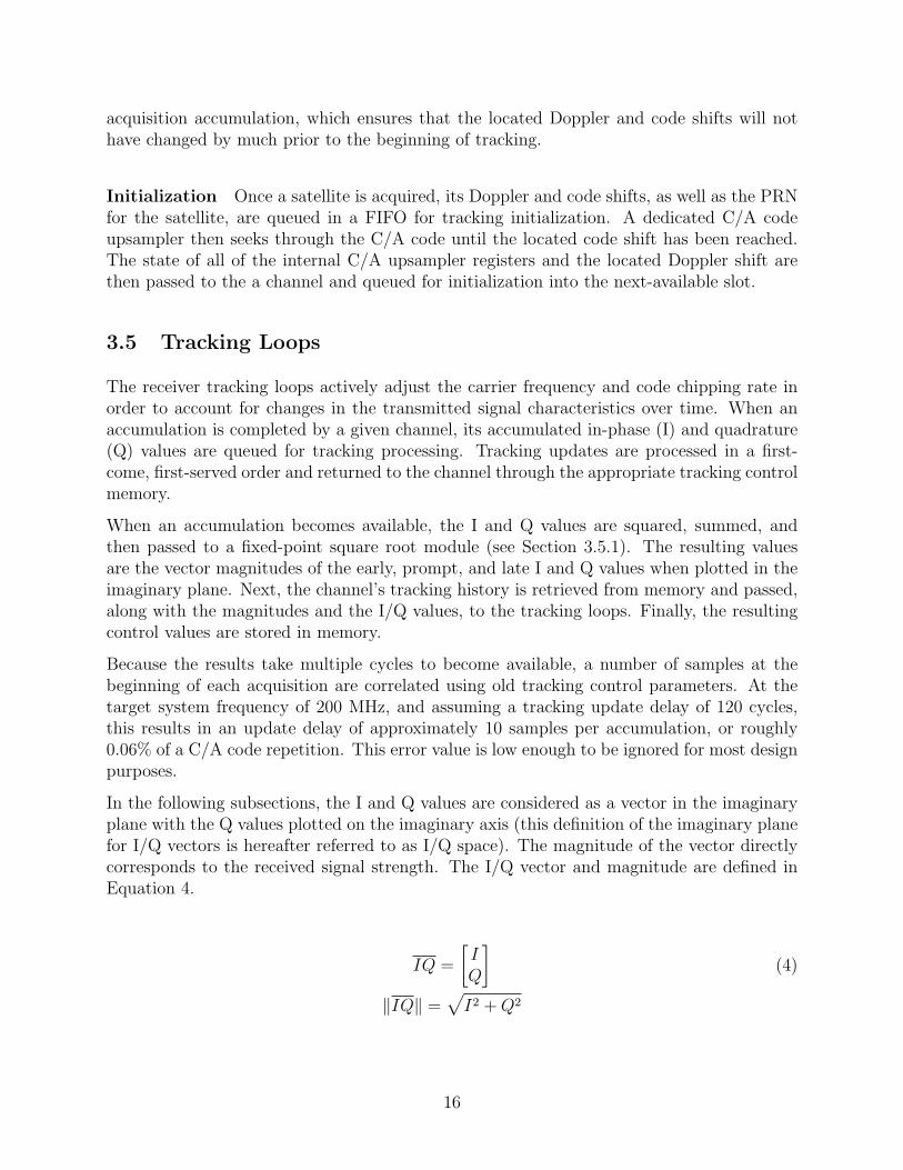
In the following subsections, the I and Q values are considered as a vector in the imaginaryplane with the Q values plotted on the imaginary axis (this definition of the imaginary planefor I/Q vectors is hereafter referred to as I/Q space). The magnitude of the vector directlycorresponds to the received signal strength. The I/Q vector and magnitude are defined inEquation 4.
IQ =
[IQ
](4)
‖IQ‖ =√I2 +Q2
16
3.5.1 Square Root
To calculate the square roots required by the tracking loops, a module was developed tocalculate a fixed-point integer approximation to the square root of an input number using aniterative algorithm requiring only bit-shifting, addition, and bitwise logical operations. Theiterative algorithm implemented is based on the Friden algorithm, dating back to mechanicalcalculators. [1] Rather than using a Newton-Rapshon scheme to calculate the square root,which requires division and an unknown number of iterations to converge to the required pre-cision, the Friden-based algorithm uses a binary-adapted ”sum of the odd integers” approachto estimate the square root of an input number in a number of iterations approximately equalto the bit width of the input number. It relies on the fact that the nth partial sum Sn of thesequence
s = 1, 3, 5, 7, ..., 2k + 1, 0 ≤ k ≤ ∞
can be written as
Sn =n−1∑k=0
2k + 1 = p2
where p is a positive integer. By iteratively subtracting multiples of elements of the sequences and comparing the divisor and remainder, successive digits of the square root can becomputed using bit shifts instead of multiplication and division.
3.5.2 Delay-Locked Loop (DLL)
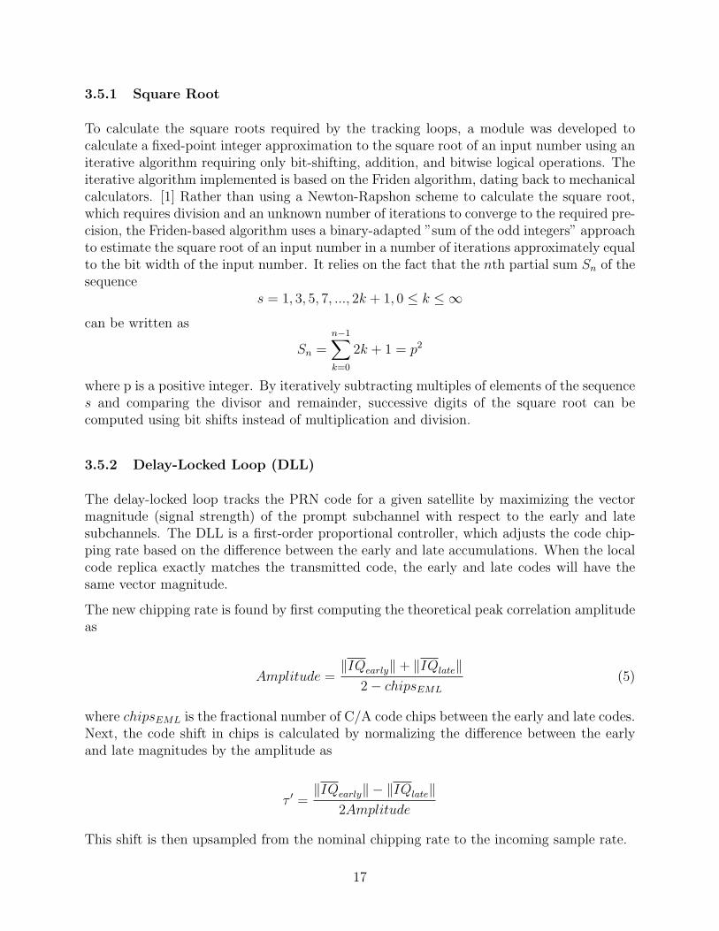
The delay-locked loop tracks the PRN code for a given satellite by maximizing the vectormagnitude (signal strength) of the prompt subchannel with respect to the early and latesubchannels. The DLL is a first-order proportional controller, which adjusts the code chip-ping rate based on the difference between the early and late accumulations. When the localcode replica exactly matches the transmitted code, the early and late codes will have thesame vector magnitude.
The new chipping rate is found by first computing the theoretical peak correlation amplitudeas
Amplitude =‖IQearly‖+ ‖IQlate‖
2− chipsEML
(5)
where chipsEML is the fractional number of C/A code chips between the early and late codes.Next, the code shift in chips is calculated by normalizing the difference between the earlyand late magnitudes by the amplitude as
τ ′ =‖IQearly‖ − ‖IQlate‖
2Amplitude
This shift is then upsampled from the nominal chipping rate to the incoming sample rate.
17
τ ′up = τ ′fs
fC/A
=‖IQearly‖ − ‖IQlate‖‖IQearly‖+ ‖IQlate‖
((2− chipsEML)fs
2AmplitudefC/A
)(6)
Finally, the chipping rate is calculated by applying a proportional gain term to Equation 6and adding the correction to the nominal chipping rate as
fC/A,k+1 = fC/A(1 +Kτ ′)
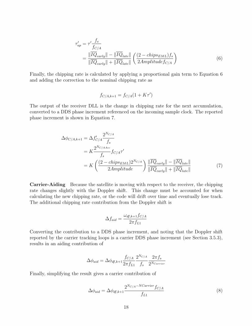
The output of the receiver DLL is the change in chipping rate for the next accumulation,converted to a DDS phase increment referenced on the incoming sample clock. The reportedphase increment is shown in Equation 7.
∆φC/A,k+1 = ∆f ′C/A
2NC/A
fs
= K2NC/AAcc
fs
fC/Aτ′
= K
((2− chipsEML)2NC/A
2Amplitude
) ‖IQearly‖ − ‖IQlate‖‖IQearly‖+ ‖IQlate‖
(7)
Carrier-Aiding Because the satellite is moving with respect to the receiver, the chippingrate changes slightly with the Doppler shift. This change must be accounted for whencalculating the new chipping rate, or the code will drift over time and eventually lose track.The additional chipping rate contribution from the Doppler shift is
∆faid =ωdf,k+1fC/A
2πfL1
Converting the contribution to a DDS phase increment, and noting that the Doppler shiftreported by the carrier tracking loops is a carrier DDS phase increment (see Section 3.5.3),results in an aiding contribution of
∆φaid = ∆φdf,k+1
fC/A
2πfL1
2NC/A
fs
2πfs
2NCarrier
Finally, simplifying the result gives a carrier contribution of
∆φaid = ∆φdf,k+1
2NC/A−NCarrierfC/A
fL1
(8)
18
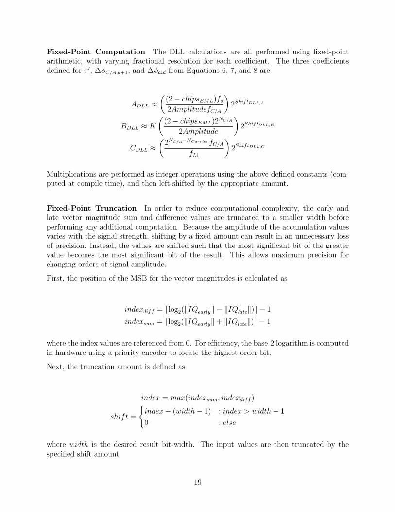
Fixed-Point Computation The DLL calculations are all performed using fixed-pointarithmetic, with varying fractional resolution for each coefficient. The three coefficientsdefined for τ ′, ∆φC/A,k+1, and ∆φaid from Equations 6, 7, and 8 are
ADLL ≈(
(2− chipsEML)fs
2AmplitudefC/A
)2ShiftDLL,A
BDLL ≈ K
((2− chipsEML)2NC/A
2Amplitude
)2ShiftDLL,B
CDLL ≈(
2NC/A−NCarrierfC/A
fL1
)2ShiftDLL,C
Multiplications are performed as integer operations using the above-defined constants (com-puted at compile time), and then left-shifted by the appropriate amount.
Fixed-Point Truncation In order to reduce computational complexity, the early andlate vector magnitude sum and difference values are truncated to a smaller width beforeperforming any additional computation. Because the amplitude of the accumulation valuesvaries with the signal strength, shifting by a fixed amount can result in an unnecessary lossof precision. Instead, the values are shifted such that the most significant bit of the greatervalue becomes the most significant bit of the result. This allows maximum precision forchanging orders of signal amplitude.
First, the position of the MSB for the vector magnitudes is calculated as
indexdiff = dlog2(‖IQearly‖ − ‖IQlate‖)e − 1
indexsum = dlog2(‖IQearly‖+ ‖IQlate‖)e − 1
where the index values are referenced from 0. For efficiency, the base-2 logarithm is computedin hardware using a priority encoder to locate the highest-order bit.
Next, the truncation amount is defined as
index = max(indexsum, indexdiff )
shift =
{index− (width− 1) : index > width− 1
0 : else
where width is the desired result bit-width. The input values are then truncated by thespecified shift amount.
19
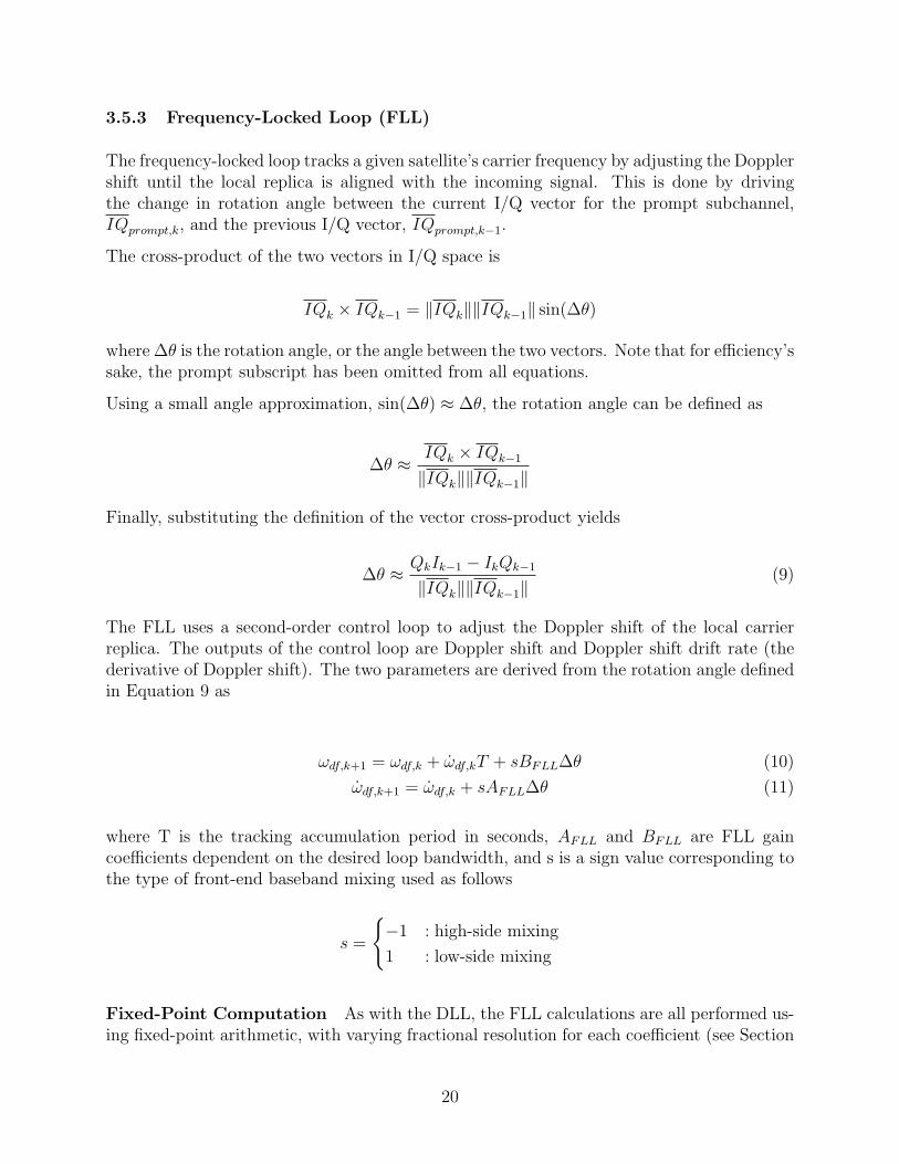
3.5.3 Frequency-Locked Loop (FLL)
The frequency-locked loop tracks a given satellite’s carrier frequency by adjusting the Dopplershift until the local replica is aligned with the incoming signal. This is done by drivingthe change in rotation angle between the current I/Q vector for the prompt subchannel,IQprompt,k, and the previous I/Q vector, IQprompt,k−1.
The cross-product of the two vectors in I/Q space is
IQk × IQk−1 = ‖IQk‖‖IQk−1‖ sin(∆θ)
where ∆θ is the rotation angle, or the angle between the two vectors. Note that for efficiency’ssake, the prompt subscript has been omitted from all equations.
Using a small angle approximation, sin(∆θ) ≈ ∆θ, the rotation angle can be defined as
∆θ ≈IQk × IQk−1
‖IQk‖‖IQk−1‖
Finally, substituting the definition of the vector cross-product yields
∆θ ≈ QkIk−1 − IkQk−1
‖IQk‖‖IQk−1‖(9)
The FLL uses a second-order control loop to adjust the Doppler shift of the local carrierreplica. The outputs of the control loop are Doppler shift and Doppler shift drift rate (thederivative of Doppler shift). The two parameters are derived from the rotation angle definedin Equation 9 as
ωdf,k+1 = ωdf,k + ω̇df,kT + sBFLL∆θ (10)
ω̇df,k+1 = ω̇df,k + sAFLL∆θ (11)
where T is the tracking accumulation period in seconds, AFLL and BFLL are FLL gaincoefficients dependent on the desired loop bandwidth, and s is a sign value corresponding tothe type of front-end baseband mixing used as follows
s =
{−1 : high-side mixing
1 : low-side mixing
Fixed-Point Computation As with the DLL, the FLL calculations are all performed us-ing fixed-point arithmetic, with varying fractional resolution for each coefficient (see Section
20
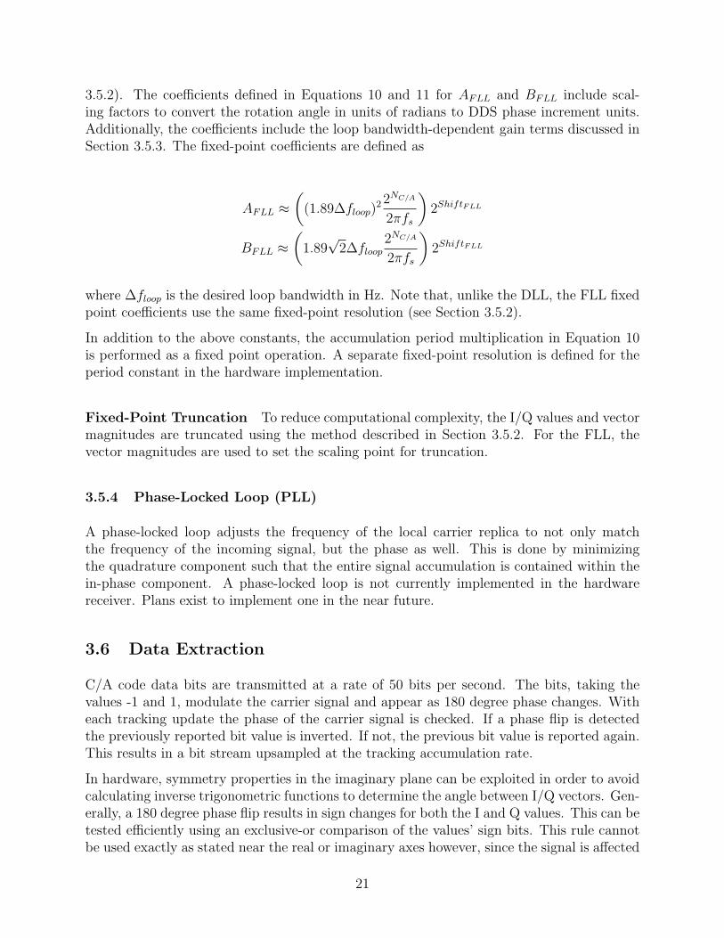
3.5.2). The coefficients defined in Equations 10 and 11 for AFLL and BFLL include scal-ing factors to convert the rotation angle in units of radians to DDS phase increment units.Additionally, the coefficients include the loop bandwidth-dependent gain terms discussed inSection 3.5.3. The fixed-point coefficients are defined as
AFLL ≈(
(1.89∆floop)2 2NC/A
2πfs
)2ShiftFLL
BFLL ≈(
1.89√
2∆floop2NC/A
2πfs
)2ShiftFLL
where ∆floop is the desired loop bandwidth in Hz. Note that, unlike the DLL, the FLL fixedpoint coefficients use the same fixed-point resolution (see Section 3.5.2).
In addition to the above constants, the accumulation period multiplication in Equation 10is performed as a fixed point operation. A separate fixed-point resolution is defined for theperiod constant in the hardware implementation.
Fixed-Point Truncation To reduce computational complexity, the I/Q values and vectormagnitudes are truncated using the method described in Section 3.5.2. For the FLL, thevector magnitudes are used to set the scaling point for truncation.
3.5.4 Phase-Locked Loop (PLL)
A phase-locked loop adjusts the frequency of the local carrier replica to not only matchthe frequency of the incoming signal, but the phase as well. This is done by minimizingthe quadrature component such that the entire signal accumulation is contained within thein-phase component. A phase-locked loop is not currently implemented in the hardwarereceiver. Plans exist to implement one in the near future.
3.6 Data Extraction
C/A code data bits are transmitted at a rate of 50 bits per second. The bits, taking thevalues -1 and 1, modulate the carrier signal and appear as 180 degree phase changes. Witheach tracking update the phase of the carrier signal is checked. If a phase flip is detectedthe previously reported bit value is inverted. If not, the previous bit value is reported again.This results in a bit stream upsampled at the tracking accumulation rate.
In hardware, symmetry properties in the imaginary plane can be exploited in order to avoidcalculating inverse trigonometric functions to determine the angle between I/Q vectors. Gen-erally, a 180 degree phase flip results in sign changes for both the I and Q values. This can betested efficiently using an exclusive-or comparison of the values’ sign bits. This rule cannotbe used exactly as stated near the real or imaginary axes however, since the signal is affected
21
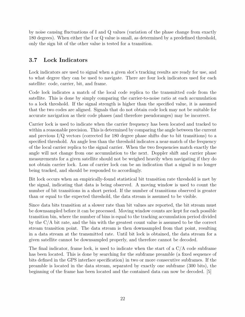
by noise causing fluctuations of I and Q values (variation of the phase change from exactly180 degrees). When either the I or Q value is small, as determined by a predefined threshold,only the sign bit of the other value is tested for a transition.
3.7 Lock Indicators
Lock indicators are used to signal when a given slot’s tracking results are ready for use, andto what degree they can be used to navigate. There are four lock indicators used for eachsatellite: code, carrier, bit, and frame.
Code lock indicates a match of the local code replica to the transmitted code from thesatellite. This is done by simply comparing the carrier-to-noise ratio at each accumulationto a lock threshold. If the signal strength is higher than the specified value, it is assumedthat the two codes are aligned. Signals that do not obtain code lock may not be suitable foraccurate navigation as their code phases (and therefore pseudoranges) may be incorrect.
Carrier lock is used to indicate when the carrier frequency has been located and tracked towithin a reasonable precision. This is determined by comparing the angle between the currentand previous I/Q vectors (corrected for 180 degree phase shifts due to bit transitions) to aspecified threshold. An angle less than the threshold indicates a near-match of the frequencyof the local carrier replica to the signal carrier. When the two frequencies match exactly theangle will not change from one accumulation to the next. Doppler shift and carrier phasemeasurements for a given satellite should not be weighed heavily when navigating if they donot obtain carrier lock. Loss of carrier lock can be an indication that a signal is no longerbeing tracked, and should be responded to accordingly.
Bit lock occurs when an empirically-found statistical bit transition rate threshold is met bythe signal, indicating that data is being observed. A moving window is used to count thenumber of bit transitions in a short period. If the number of transitions observed is greaterthan or equal to the expected threshold, the data stream is assumed to be visible.
Since data bits transition at a slower rate than bit values are reported, the bit stream mustbe downsampled before it can be processed. Moving window counts are kept for each possibletransition bin, where the number of bins is equal to the tracking accumulation period dividedby the C/A bit rate, and the bin with the greatest count value is assumed to be the correctstream transition point. The data stream is then downsampled from that point, resultingin a data stream at the transmitted rate. Until bit lock is obtained, the data stream for agiven satellite cannot be downsampled properly, and therefore cannot be decoded.
The final indicator, frame lock, is used to indicate when the start of a C/A code subframehas been located. This is done by searching for the subframe preamble (a fixed sequence ofbits defined in the GPS interface specification) in two or more consecutive subframes. If thepreamble is located in the data stream, separated by exactly one subframe (300 bits), thebeginning of the frame has been located and the contained data can now be decoded. [5]
22
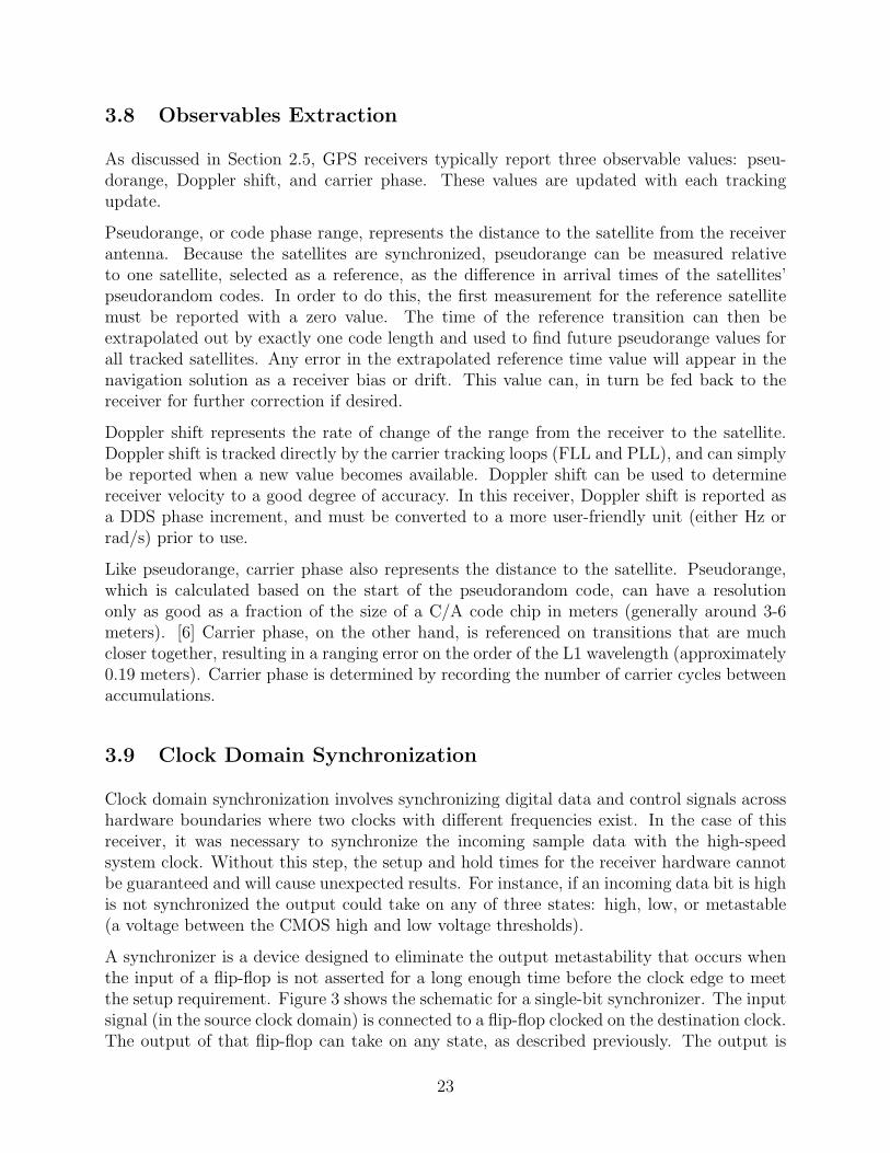
3.8 Observables Extraction
As discussed in Section 2.5, GPS receivers typically report three observable values: pseu-dorange, Doppler shift, and carrier phase. These values are updated with each trackingupdate.
Pseudorange, or code phase range, represents the distance to the satellite from the receiverantenna. Because the satellites are synchronized, pseudorange can be measured relativeto one satellite, selected as a reference, as the difference in arrival times of the satellites’pseudorandom codes. In order to do this, the first measurement for the reference satellitemust be reported with a zero value. The time of the reference transition can then beextrapolated out by exactly one code length and used to find future pseudorange values forall tracked satellites. Any error in the extrapolated reference time value will appear in thenavigation solution as a receiver bias or drift. This value can, in turn be fed back to thereceiver for further correction if desired.
Doppler shift represents the rate of change of the range from the receiver to the satellite.Doppler shift is tracked directly by the carrier tracking loops (FLL and PLL), and can simplybe reported when a new value becomes available. Doppler shift can be used to determinereceiver velocity to a good degree of accuracy. In this receiver, Doppler shift is reported asa DDS phase increment, and must be converted to a more user-friendly unit (either Hz orrad/s) prior to use.
Like pseudorange, carrier phase also represents the distance to the satellite. Pseudorange,which is calculated based on the start of the pseudorandom code, can have a resolutiononly as good as a fraction of the size of a C/A code chip in meters (generally around 3-6meters). [6] Carrier phase, on the other hand, is referenced on transitions that are muchcloser together, resulting in a ranging error on the order of the L1 wavelength (approximately0.19 meters). Carrier phase is determined by recording the number of carrier cycles betweenaccumulations.
3.9 Clock Domain Synchronization
Clock domain synchronization involves synchronizing digital data and control signals acrosshardware boundaries where two clocks with different frequencies exist. In the case of thisreceiver, it was necessary to synchronize the incoming sample data with the high-speedsystem clock. Without this step, the setup and hold times for the receiver hardware cannotbe guaranteed and will cause unexpected results. For instance, if an incoming data bit is highis not synchronized the output could take on any of three states: high, low, or metastable(a voltage between the CMOS high and low voltage thresholds).
A synchronizer is a device designed to eliminate the output metastability that occurs whenthe input of a flip-flop is not asserted for a long enough time before the clock edge to meetthe setup requirement. Figure 3 shows the schematic for a single-bit synchronizer. The inputsignal (in the source clock domain) is connected to a flip-flop clocked on the destination clock.The output of that flip-flop can take on any state, as described previously. The output is
23
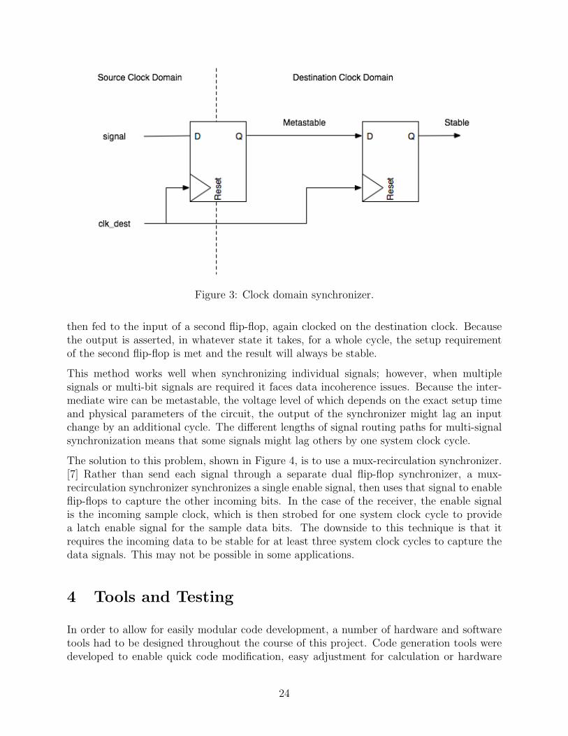
Figure 3: Clock domain synchronizer.
then fed to the input of a second flip-flop, again clocked on the destination clock. Becausethe output is asserted, in whatever state it takes, for a whole cycle, the setup requirementof the second flip-flop is met and the result will always be stable.
This method works well when synchronizing individual signals; however, when multiplesignals or multi-bit signals are required it faces data incoherence issues. Because the inter-mediate wire can be metastable, the voltage level of which depends on the exact setup timeand physical parameters of the circuit, the output of the synchronizer might lag an inputchange by an additional cycle. The different lengths of signal routing paths for multi-signalsynchronization means that some signals might lag others by one system clock cycle.
The solution to this problem, shown in Figure 4, is to use a mux-recirculation synchronizer.[7] Rather than send each signal through a separate dual flip-flop synchronizer, a mux-recirculation synchronizer synchronizes a single enable signal, then uses that signal to enableflip-flops to capture the other incoming bits. In the case of the receiver, the enable signalis the incoming sample clock, which is then strobed for one system clock cycle to providea latch enable signal for the sample data bits. The downside to this technique is that itrequires the incoming data to be stable for at least three system clock cycles to capture thedata signals. This may not be possible in some applications.
4 Tools and Testing
In order to allow for easily modular code development, a number of hardware and softwaretools had to be designed throughout the course of this project. Code generation tools weredeveloped to enable quick code modification, easy adjustment for calculation or hardware
24
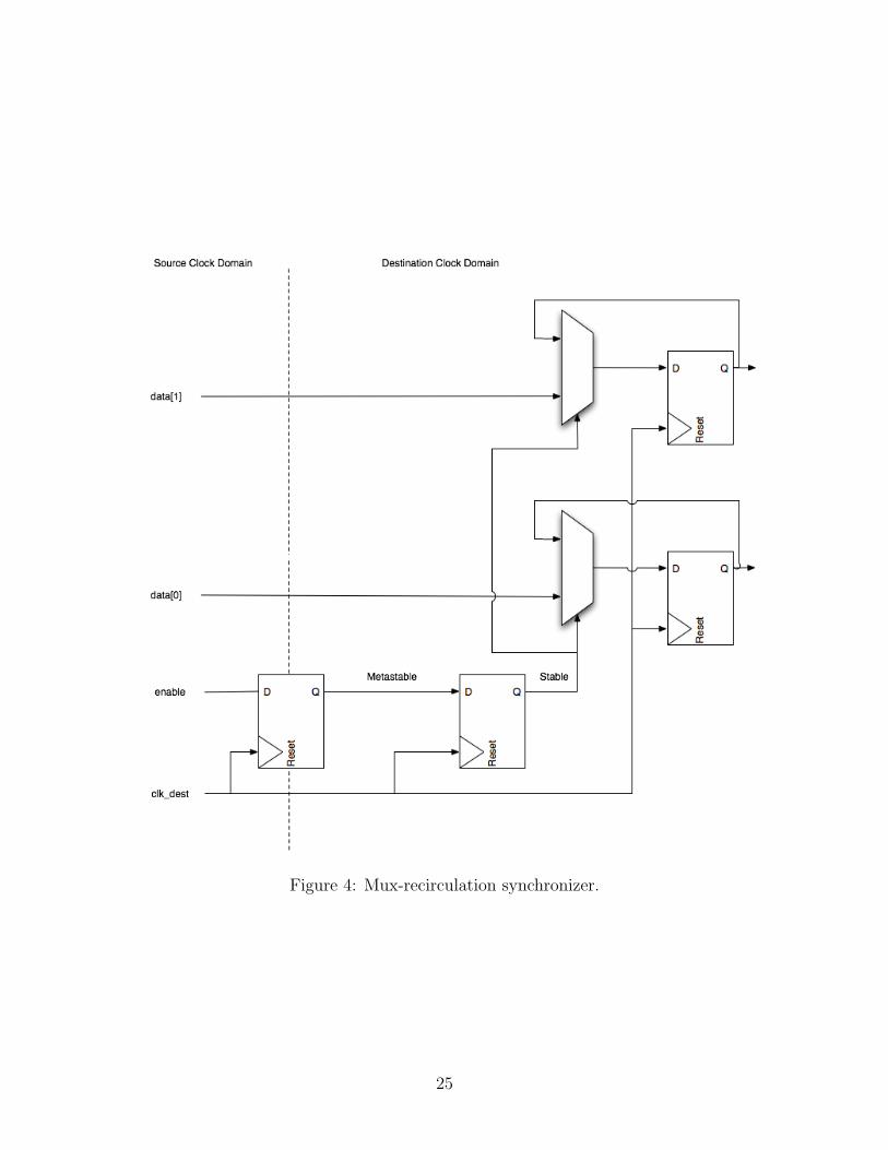
Figure 4: Mux-recirculation synchronizer.
25
changes, including changing of signal widths, compile-time determination of required signalwidths and bit ranges, optimizing design efficiency on the fly, and repeatable testing withreal-time data log playback capabilities. Additional software tools were created to gener-ate controllable data logs, and to test and tune fixed-point tracking algorithms prior todeveloping hardware components.
4.1 Verilog Defines Parser
The Defines Parser, or defparser, is a Java utility designed to automatically generate Ver-ilog include files from a set of interdependent definitions. For each variable defined in theinput files, defparser generates a Verilog macro by expanding the provided value expression,recursively expanding dependencies as needed. Values can be specified using a set of mathe-matical expressions and supported functions, as well as values from any other macros definedin the scope. This allows for quick modification of signal widths based on maximum repre-sentable values, wire bit ranges, fixed-width Verilog constants, and other useful parameters.Additionally, calculations can be maintained in floating-point for maximum precision, andconverted to fixed-point or integer format when generated. This allows for the automaticgeneration of accurate fixed-point constants based on a smaller set of global definitions.
In Verilog, all macros are available within a global scope from the point at which they aredefined. This means that a macro defined in one file will be available in all subsequentlycompiled files. An additional feature of defparser is the ability to generate a file containingVerilog undefine directives for each macro specified in the input files. This file can then beincluded at the beginning of a Verilog file in order to clear the macro replacement table andeliminate this problem completely.
Finally, defparser can be used to find overlapping macro names, warning the user of potentialmacro redefinitions, which might otherwise cause unexpected errors.
A future goal for defparser is the ability to generate dependancy files for a supplied inputfile. Such files could then be included in a project make flow, causing header files to berecompiled automatically whenever a required source file is changed.
4.2 Verilog Preprocessor
The Verilog Preprocessor is a set of Python scripts used as a means to perfom code generationand in-line arithmetic for code generalization beyond the ability of the Verilog language.Due to the effort to keep Verilog code as general as possible, there were many instances inwhich code generation was required that could not be performed using Verilog generate
statements and other built-in options. The preprocessor allows a developer to use the fullpower of the Python programming language to perform these operations. The developersimply writes a Verilog module as per usual, but has the option to insert Python code at anytime using a series of predefined delimiters: <? and ?> for begin and end, respectively. Whenthe preprocessor script is executed on this file, the Python code within these delimiters is
26
executed in a Python environment, and the code surrounded by the delimiters as well asthe delimiters themselves are replaced by the output of the Python code in the outputfile. This affords many opportunities to the user which are not available in the Veriloglanguage; for example, a developer might use the preprocessor to automatically generate thecase statement conditions for a lookup table at compile-time, based on a set of macros orparameters defined by the user. This task is not possible to do on-the-fly in Verilog codealone, and traditionally is done manually, making the hardware significantly less general andintroducing room for error if the system parameters change without the code being modified.
In addition to executing Python code and printing an output file, the preprocessor parses theinput file to locate any defined macros or header files. All header files are parsed recursively,moving ”up the tree” until a top-level header file is reached, and all defined macros arestored in a dictionary object at runtime. This allows the developer to use predefined Verilogmacros as variables in embedded Python code, which is useful for such tasks as controllingprogram flow via if/else statements or setting the number of iterations a loop is to perform.
Future goals for the preprocessor include support for concise Python code insertion (forexample, abbreviating print statements for common expressions such as wire or input decla-rations) and improved parsing of module instantiation, to support recursive preprocessing ofsource files. These improvements will both streamline preprocessor code creation and easethe insertion of the preprocessor into project make flow.
4.3 High-Speed Ethernet Data Feed
In designing the hardware receiver, it quickly became clear that a system was needed toprovide repeatable testing capabilities for development. Developing and debugging the in-dividual components of the receiver from a live, uncontrollable, and noise-affected front-enddata source was not feasible. The sample rate used in the hardware receiver, required dueto the C/A code chipping rate, necessitated the design of a high-speed hardware data feedsystem. The bandwidth required by the sample data rate is
fs = 16.8 Msamp/sec
NSample = 3 bits (sign/magnitude)
BW = fsNSample = 50.4 Mbps
This bandwidth is too large for most common (simple) communication schemes – particularlythose easily interfaceable to a computer without the addition of custom hardware. Thesolution is to feed the data over Ethernet, which is capable of bandwidth up 100 Mbps.
The DE2 development board developed by Terasic Technologies for the Altera Cyclone IIFPGA contains a Davicom DM9000A Ethernet controller. The DM9000A provides bidirec-tional hardware Ethernet functionality, designed to interface to a processor using a 16-bitdata bus. [2] A hardware module was developed in Verilog to interface to and control theDM9000A at full rate. The module generates the required Ethernet control clock, issues the
27
required reset sequence, handles received interrupts, and reads from/writes to asynchronousdata FIFOs such that Ethernet connectivity can easily be added to hardware operating atany clock speed.
The received Ethernet frame data is then passed to a packet processor, which filters thepacket stream by EtherType, discarding any unwanted packets. After filtering, the remainingdata is placed into a FIFO and read out into a sample stream generating buffer. The systemgenerates a local sample clock, and data samples are removed from the buffer on each cycleand passed to the hardware.
A C utility was developed in conjunction with the hardware data feed, which is capable oftransmitting data from a binary file using a user-specified burst size and bit rate. Whencombined, the data feed hardware and utility allow generated or recorded data logs to beplayed back into the receiver for easily-repeatable testing.
4.4 Data Generation
In order to test various aspects of the receiver independently of others, it was required todesign a data set generation tool capable of producing sample data using specified param-eters, that could then be passed to the receiver as needed. The data log generation utilitywas built in MATLAB and is capable of creating a sample set of any desired length with aspecified PRN, Doppler shift, and code shift. The utility can additionally inject noise intothe signal, and generate Doppler ramps over time, for additional testing as needed.
The resulting log data can be used in MATLAB for further testing, or can be saved as alog file for transfer to the hardware. A MATLAB MEX function was written in C, capableof saving a sample data vector to a binary file in either the hardware or software receiversupported formats. The hardware format involves packaging 3-bit, sign/magnitude samplevalues into 8-bit words. The software format requires that the values be scaled to two bits(sign/magnitude), then packaged 16 samples at a time.
4.4.1 Fixed-Point Implementation
MATLAB scripts were developed to perform the fixed-point calculations in the exact se-quence in which they are performed in the receiver, including all truncation and loss steps,such that the receiver tracking outputs could be functionally verified. The test scripts re-port the floating-point truth values, the non-truncated fixed-point values, and the truncatedfixed-point values. These values can be generated using measured accumulation and trackinghistory values reported by the receiver and then be compared to the hardware implementa-tion results to locate errors.
28
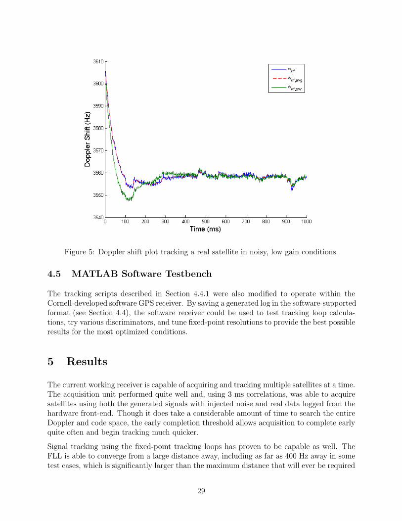
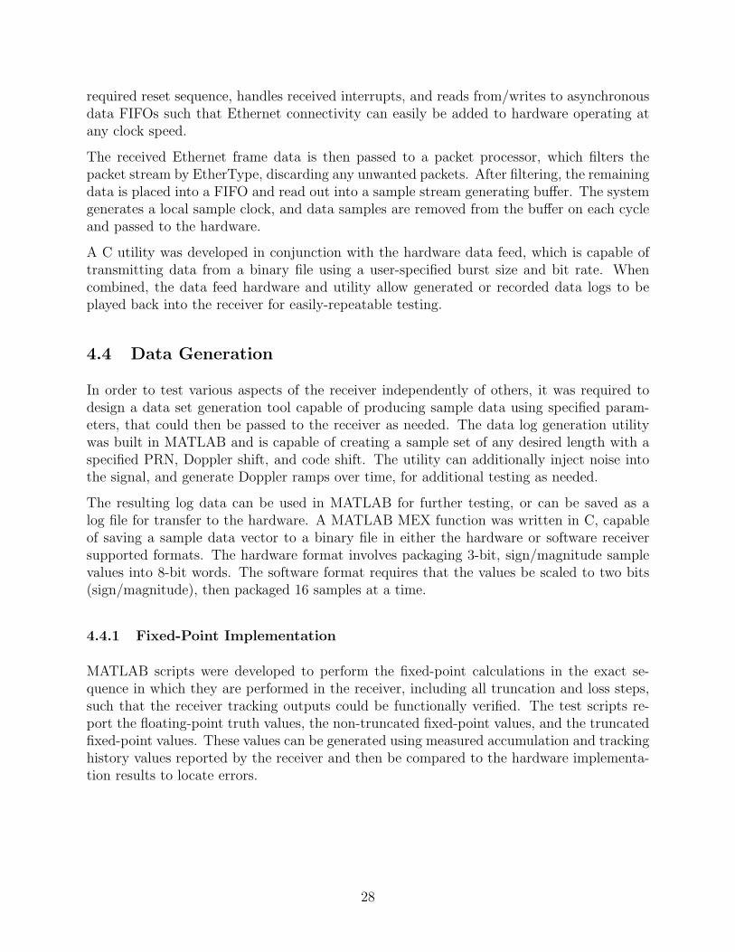
Figure 5: Doppler shift plot tracking a real satellite in noisy, low gain conditions.
4.5 MATLAB Software Testbench
The tracking scripts described in Section 4.4.1 were also modified to operate within theCornell-developed software GPS receiver. By saving a generated log in the software-supportedformat (see Section 4.4), the software receiver could be used to test tracking loop calcula-tions, try various discriminators, and tune fixed-point resolutions to provide the best possibleresults for the most optimized conditions.
5 Results
The current working receiver is capable of acquiring and tracking multiple satellites at a time.The acquisition unit performed quite well and, using 3 ms correlations, was able to acquiresatellites using both the generated signals with injected noise and real data logged from thehardware front-end. Though it does take a considerable amount of time to search the entireDoppler and code space, the early completion threshold allows acquisition to complete earlyquite often and begin tracking much quicker.
Signal tracking using the fixed-point tracking loops has proven to be capable as well. TheFLL is able to converge from a large distance away, including as far as 400 Hz away in sometest cases, which is significantly larger than the maximum distance that will ever be required
29
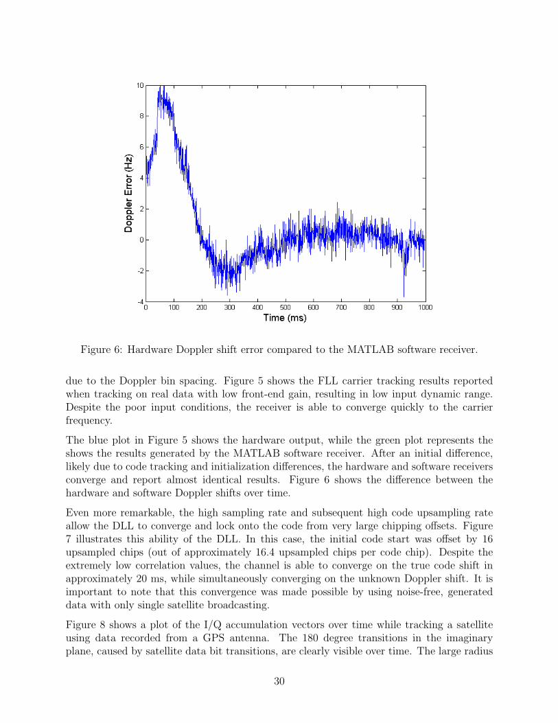
Figure 6: Hardware Doppler shift error compared to the MATLAB software receiver.
due to the Doppler bin spacing. Figure 5 shows the FLL carrier tracking results reportedwhen tracking on real data with low front-end gain, resulting in low input dynamic range.Despite the poor input conditions, the receiver is able to converge quickly to the carrierfrequency.
The blue plot in Figure 5 shows the hardware output, while the green plot represents theshows the results generated by the MATLAB software receiver. After an initial difference,likely due to code tracking and initialization differences, the hardware and software receiversconverge and report almost identical results. Figure 6 shows the difference between thehardware and software Doppler shifts over time.
Even more remarkable, the high sampling rate and subsequent high code upsampling rateallow the DLL to converge and lock onto the code from very large chipping offsets. Figure7 illustrates this ability of the DLL. In this case, the initial code start was offset by 16upsampled chips (out of approximately 16.4 upsampled chips per code chip). Despite theextremely low correlation values, the channel is able to converge on the true code shift inapproximately 20 ms, while simultaneously converging on the unknown Doppler shift. It isimportant to note that this convergence was made possible by using noise-free, generateddata with only single satellite broadcasting.
Figure 8 shows a plot of the I/Q accumulation vectors over time while tracking a satelliteusing data recorded from a GPS antenna. The 180 degree transitions in the imaginaryplane, caused by satellite data bit transitions, are clearly visible over time. The large radius
30
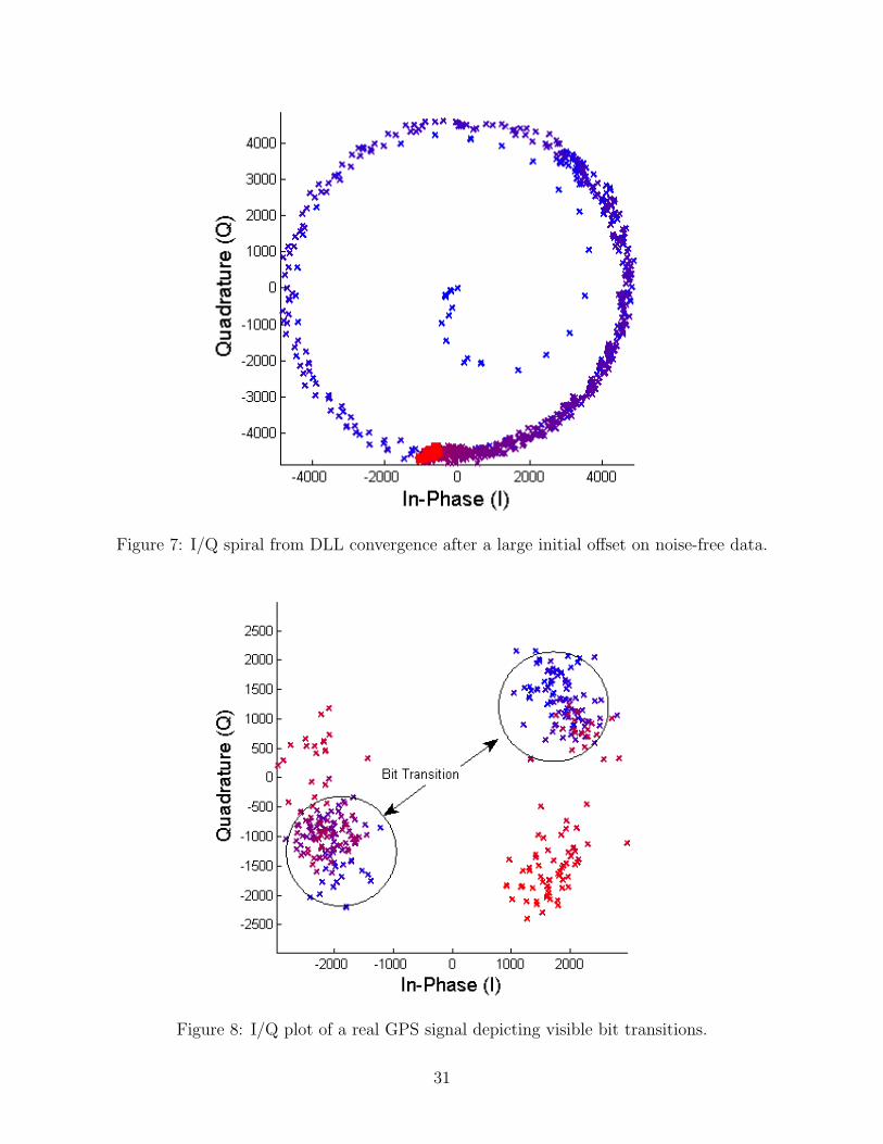
Figure 7: I/Q spiral from DLL convergence after a large initial offset on noise-free data.
Figure 8: I/Q plot of a real GPS signal depicting visible bit transitions.
31
of the accumulation clusters is caused by signal noise and reduced dynamic range from lowfront-end gain.
5.1 Hardware
The hardware fits quite well onto the Altera Cyclone II FPGA used for this project. TheFPGA has a total of ∼ 33k logic elements, 483,840 bits of on-chip memory, and 70 9-bithardware multipliers. The three major receiver components, the channel, the acquisitionunit, and the tracking loops take approximately 1,500, 3,000, and 6,000 logic elements re-spectively. A single memory bank uses approximately 193,500 bits of memory for sampledata storage. Combined with a Nios II microprocessor used for data packaging, the currentsystem uses approximately 34% of the total available resources.
By sharing the largest hardware component, the tracking loops, across all hardware channels,the receiver is capable of implementing quite a large number of parallel satellite tracking slotsfor very little added hardware usage. This leaves the majority of the remaining hardwarefor additional acquisition accumulators to speed up the acquisition process.
The modular design of the system makes it very easy to change as needed to accommodatenew designs, hardware, and application-specific parameters. By carefully and meticulouslyusing Verilog macros and parameters, most all of the hardware can be entirely reconfiguredby modifying a small set of globally-defined constants in a single header file. Similarly,precision of fixed-point calculations used in the tracking loops can be easily changed asneeded, simply by changing the desired fractional width definition constants.
5.2 Issues
The acquisition unit currently uses a fixed memory bank, as opposed to swapping betweentwo memory banks to refresh stale data. Because of this, code and Doppler drift accu-mulate during the acquisition process and make it more difficult to initialize tracking afterlong searches. This is particularly true for weaker signal strength satellites, including low-eleveation satellites. Plans are in place to implement memory bank switching in anotherMEng project in the near future (see Section 6), enabling proper real-time acquisition.
The receiver does not currently contain lock indication or data extraction functionality.These functions have been planned however, and will be added to the hardware in the nearfuture.
Due to time constraints, not all hardware was able to be optimized to run at the targetsystem clock speed of 200 MHz. The results of this are increased acquisition time andslightly decreased tracking resolution. The time to completion for acquisition of a singlePRN is currently approximately 2.5 minutes when an early-termination does not occur.Tracking updates take approximately twice as long to complete, with respect to number ofsamples missed, than originally intended. This additional delay, however, results in a totalloss of approximately 23 samples, or 0.13% of the total accumulation size.
32
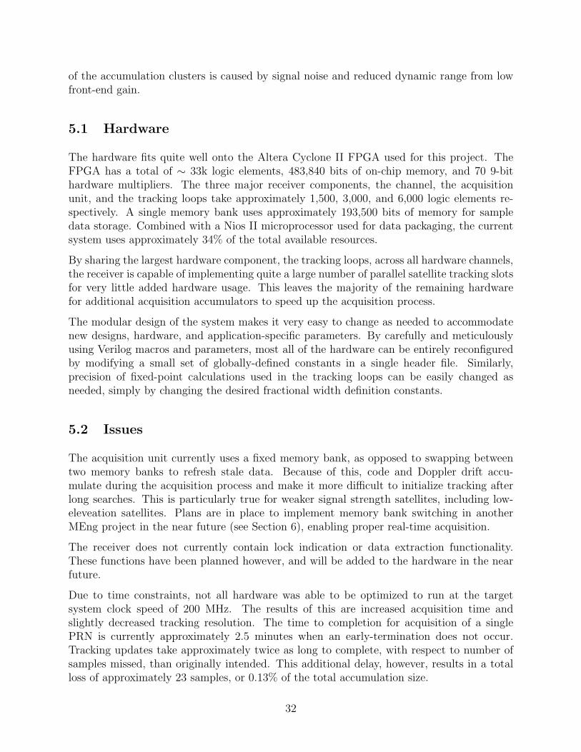
Figure 9: Carrier tracking limit cycle with a ±0.1 Hz oscillation.
Figure 9 shows a noticeable limit cycle, manifested as high-frequency Doppler shift jitter,that exists when tracking carrier using the hardware FLL. Using generated data with nonoise injection and a constant Doppler shift, the tracked Doppler shift varies by up to about±0.2 Hz peak to peak in steady state. This limit cycle is likely a result of three factors: thenonlinearity introduced by the small-angle approximation used in Equation 9, truncationerror due to the fixed-point calculations, and transport delay introduced by the computationtime required by the tracking loops.
6 Future Goals
This project is to be completed in two parts. The first part includes the major functionalcomponents of the receiver itself as described in this paper. The second part includes com-pletion of the receiver, including data extraction and decoding, observables extraction, andthe addition of a number of features including, but not limited to, WAAS navigational cor-rections, warm-start acquisition, a Kalman filter-based navigation solution implemented inC, and a graphical user interface.
The receiver hardware was developed primarily by Adam Shapiro, with assistance from TomChatt, in the Fall of 2009. The completion of the receiver and addition of features will becompleted by Tom Chatt, with assistance from Adam Shapiro, in the Spring of 2010.
33
7 Acknowledgments
I would like to thank Professor Bruce Land for his endless support and advice. His help inthe development of the receiver has been invaluable, and his unending knowledge and storieshave kept me well educated, focused, and very entertained.
I would also like to thank Professor Paul Kintner, Professor Mark Psiaki, Brady O’Hanlon,and the Cornell GNSS Research Group for their help and support.
Finally, I would like to thank the Cornell University Department of Electrical and ComputerEngineering for a terrific education and all of the opportunities to learn and grow it provided.
8 Appendix
All source code, tools, and documentation for this project are available on the web at thefollowing URL: http://cu-hw-gps.googlecode.com. This project is open to the public,and is licensed under the GNU General Public License, version 2.
References
[1] Jack W. Crenshaw. Integer square roots. http://www.embedded.com/98/9802fe2.htm,2008.
[2] Davicom Semiconductor, Inc. DM9000A Ethernet Controller Datasheet, May 2006.
[3] Maxim Integrated Products. MAX2741 Integrated L1-Band GPS Receiver Datasheet,January 2005.
[4] Pratap Misra and Per Enge. Global Positioning System: Signals, Measurements, andPerformance. Ganga-Jamuna Press, 2 edition, 2006.
[5] Navstar GPS Space Segment. Navstar Global Positioning System Interface Specification(IS-GPS-200), Rev. D, March 2006.
[6] Trimble. How gps works. http://www.trimble.com/gps/sub_phases.shtml, 2009.
[7] Saurabh Verma, Ashima S. Dabare, and Atrenta. Understanding clock domaincrossing issues. http://www.embedded.com/columns/technicalinsights/205202134?_requestid=744, 2007.
[8] J. F. Wakerly. Digital Design: Principles and Practice. Prentice Hall, 4 edition, 2006.
34