Embed Size (px)
Citation preview
HVL and SLL 5-Minute Guide Contents
Texas Instruments • Analog Products 2
Introduction . . . . . . . . . . . . . . . . . . . . . . . . .3Linear and Logic New-Product Priorities
Computing . . . . . . . . . . . . . . . . . . . . . . . . . .4Voltage-Level TranslationPCI Express® MultiplexingUSB, LAN, Video MultiplexingI2C I/O Expansion and LED DriverRS-232 Serial Port InterfaceESD Protection
Notebook . . . . . . . . . . . . . . . . . . . . . . . . . .12PCI Express® MultiplexingLVDS MultiplexingUSB 2.0 SwitchHD Audio Bus TranslatorESD ProtectionARM® Microprocessor Platform NetbookARM® Platform NetbookLoad SwitchesLDO Voltage Regulators
Server/Storage . . . . . . . . . . . . . . . . . . . . . .25Desktop/ServerGTL/GTL+ to LVTTL TranslationPCI Express® Signal-Switch MUXI2C and SMBus InterfaceRS-232 InterfaceESD/EMI Protection
Consumer .Medical . . . . . . . . . . . . . . . . . .35Power ManagementSignal ConditioningI2C Bus I/O ExpansionVoltage-Level TranslationESD Protection
Handsets . . . . . . . . . . . . . . . . . . . . . . . . . .41Voltage-Level TranslationAudio Signal RoutingI2C Baseband I/O ExpansionConfigurable Little LogicESD/EMI ProtectionKeypad ControlFun Light DisplayUSB InterfaceAnalog SwitchesTypical LCD Display Bus TranslationSDIO Interface ApplicationsSIM Card Interface ApplicationsTypical ESD/EMI Filter LocationsLoad SwitchesLittle Logic Package Options
Industrial .Automation . . . . . . . . . . . . . . . .59Interface—RS-232, USB, RS-485/422Relay and Motor ControlMaintenance and Control: I2C I/O ExpansionSignal ConditioningLED DriversLDO Voltage Regulators
Portable .Industrial .(PDAs/Scanners) . . . .66Multiplexing USB PeripheralsCard InterfacesInterface—RS-232, USB, RS-485/422I2C ControlESD ProtectionLoad Switches
Telecom . . . . . . . . . . . . . . . . . . . . . . . . . . .74Voltage-Level TranslationMaintenance and Control: I2C I/O Expansion,
Switches and BuffersBackplane SignalingInterface—RS-232, USB, RS-485/422LED DriversLDO Voltage Regulators
TV .and .Stereo . . . . . . . . . . . . . . . . . . . . . .81Video Input Multiplexer/Port ExpansionAudio/Video Input Multiplexer/Port ExpansionAudio Signal RoutingVideo Controller I/O ExpansionRS-232 InterfaceUSB InterfaceSystem-Level ESD ProtectionMedia/Information LCD DisplayLCD/PDP Digital TVTypical LCD MonitorLCD Monitor Power Source on SystemAnalog Switch Selection for LCD DisplaysHDMI and DVI InterfaceAnalog Switches for Set-Top BoxesESD Protection on Typical Set-Top Box Interfaces
White .Goods . . . . . . . . . . . . . . . . . . . . . . .97Relay or Motor ControlAnalog Signal RoutingMicrocontroller I/O ExpansionSignal ConditioningLED DriversLDO Voltage Regulators
HVL and SLL 5-Minute Guide Introduction
Texas Instruments • Analog Products 3
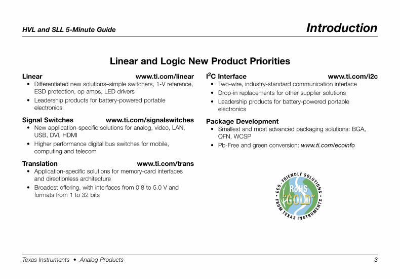
Linear . www .ti .com/linear• Differentiated new solutions–simple switchers, 1-V reference,
ESD protection, op amps, LED drivers• Leadership products for battery-powered portable
electronics
Signal .Switches . . www .ti .com/signalswitches• New application-specific solutions for analog, video, LAN,
USB, DVI, HDMI• Higher performance digital bus switches for mobile,
computing and telecom
Translation . . www .ti .com/trans• Application-specific solutions for memory-card interfaces
and directionless architecture• Broadest offering, with interfaces from 0.8 to 5.0 V and
formats from 1 to 32 bits
I2C .Interface . . www .ti .com/i2c• Two-wire, industry-standard communication interface• Drop-in replacements for other supplier solutions• Leadership products for battery-powered portable
electronics
Package .Development• Smallest and most advanced packaging solutions: BGA,
QFN, WCSP• Pb-Free and green conversion: www.ti.com/ecoinfo
Linear .and .Logic .New .Product .Priorities
HVL and SLL 5-Minute Guide Computing
Texas Instruments • Analog Products 4
Com
put
ing
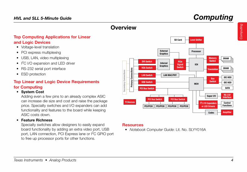
Top .Computing .Applications .for .Linear . .and .Logic .Devices
• Voltage-level translation• PCI express multiplexing• USB, LAN, video multiplexing• I2C I/O expansion and LED driver• RS-232 serial port interface• ESD protection
Top .Linear .and .Logic .Device .Requirements . .for .Computing
• System .CostAdding even a few pins to an already complex ASIC can increase die size and cost and raise the package price. Specialty switches and I/O expanders can add functionality and features to the board while keeping ASIC costs down.
• Feature .RichnessSpecialty switches allow designers to easily expand board functionality by adding an extra video port, USB port, LAN connection, PCI Express lane or I2C GPIO port to free up processor ports for other functions.
Prim
ary
Conn
ectio
ns
Seco
ndar
y Co
nnec
tions
TI Devices
RS-232Interface
Amplifier
ControlFunctions
Level ShifterSD Card
ICHDVI Switch
VGA Switch
LAN Switch
USB Switch
PCI Bus Switch
LAN MAC/PHY
Super I/O
Codec
I C I/O Expandersor LED Drivers
2
SRAM
DRAM
IDE HDD
IDE HDD
ExternalGraphics
InternalGraphics
PCIeSignalSwitch
Translation
MemorySwitch
BusSwitch
SATA
MCH
PCI Bus Switch PCI Bus Switch
PCI/PCIX PCI/PCIXPCI/PCIX PCI/PCIX
Processor
Overview
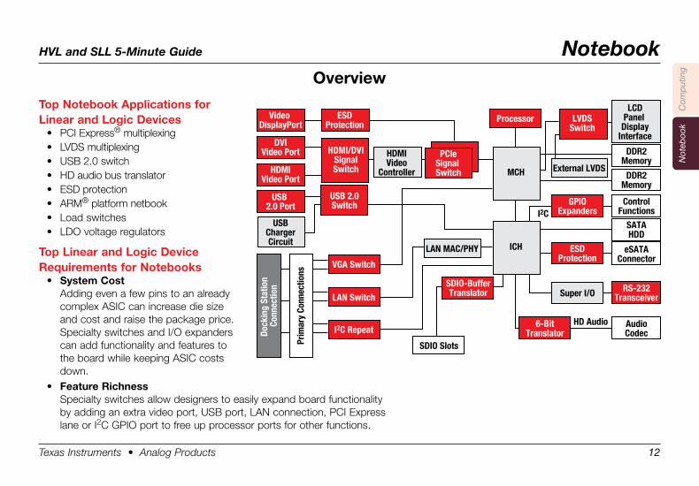
Resources• Notebook Computer Guide: Lit. No. SLYY016A
HVL and SLL 5-Minute Guide Computing
Texas Instruments • Analog Products 5
Com
put
ing
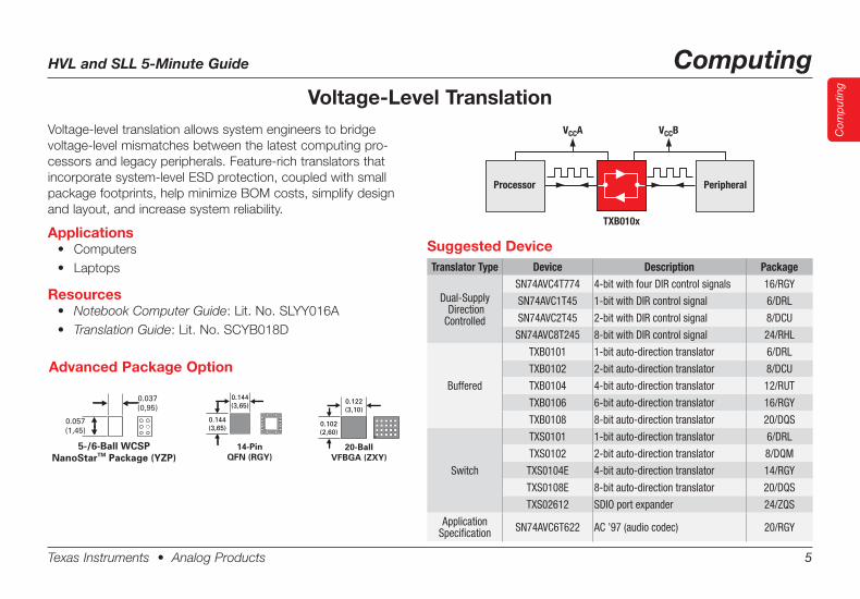
Voltage-Level TranslationVoltage-level translation allows system engineers to bridge voltage-level mismatches between the latest computing pro-cessors and legacy peripherals. Feature-rich translators that incorporate system-level ESD protection, coupled with small package footprints, help minimize BOM costs, simplify design and layout, and increase system reliability.
Applications• Computers• Laptops
Resources• Notebook Computer Guide:Lit.No.SLYY016A• Translation Guide:Lit.No.SCYB018D
Advanced Package Option
Suggested DeviceTranslator Type Device Description Package
Dual-Supply Direction Controlled
SN74AVC4T774 4-bit with four DIR control signals 16/RGY
SN74AVC1T45 1-bit with DIR control signal 6/DRL
SN74AVC2T45 2-bit with DIR control signal 8/DCU
SN74AVC8T245 8-bit with DIR control signal 24/RHL
Buffered
TXB0101 1-bit auto-direction translator 6/DRL
TXB0102 2-bit auto-direction translator 8/DCU
TXB0104 4-bit auto-direction translator 12/RUT
TXB0106 6-bit auto-direction translator 16/RGY
TXB0108 8-bit auto-direction translator 20/DQS
Switch
TXS0101 1-bit auto-direction translator 6/DRL
TXS0102 2-bit auto-direction translator 8/DQM
TXS0104E 4-bit auto-direction translator 14/RGY
TXS0108E 8-bit auto-direction translator 20/DQS
TXS02612 SDIO port expander 24/ZQS
Application Specification SN74AVC6T622 AC ’97 (audio codec) 20/RGY
0.037(0,95)
0.057(1,45)
5-/6-Ball WCSPNanoStarTM Package (YZP)
0.144(3,65)
0.144(3,65)
14-PinQFN (RGY)
0.122(3,10)
0.102(2,60)
20-BallVFBGA (ZXY)
Processor Peripheral
VCCA
TXB010x
VCCB
HVL and SLL 5-Minute Guide Computing
Texas Instruments • Analog Products 6
Com
put
ing
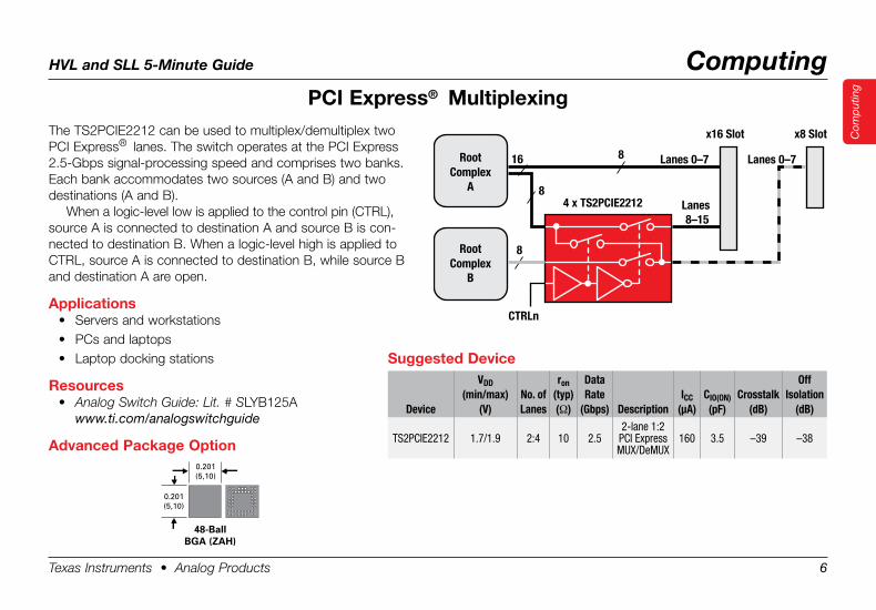
PCI .Express® . MultiplexingThe TS2PCIE2212 can be used to multiplex/demultiplex two PCI Express® lanes. The switch operates at the PCI Express 2.5-Gbps signal-processing speed and comprises two banks. Each bank accommodates two sources (A and B) and two destinations (A and B).
When a logic-level low is applied to the control pin (CTRL), source A is connected to destination A and source B is con-nected to destination B. When a logic-level high is applied to CTRL, source A is connected to destination B, while source B and destination A are open.
Applications• Servers and workstations• PCs and laptops• Laptop docking stations
Resources• Analog Switch Guide: Lit. # SLYB125A
www.ti.com/analogswitchguide
Advanced .Package .Option
Suggested .Device
Device
VDD(min/max)
(V)No. ofLanes
ron(typ)(Ω)
DataRate
(Gbps) DescriptionICC
(µA)CIO(ON)(pF)
Crosstalk(dB)
Off Isolation
(dB)
TS2PCIE2212 1.7/1.9 2:4 10 2.52-lane 1:2
PCI Express MUX/DeMUX
160 3.5 –39 –38
4 x TS2PCIE2212
Root Complex
A
Root Complex
B
16
8
8 Lanes 0–7
Lanes 8–15
x16 Slot x8 Slot
Lanes 0–7
8
CTRLn
0.201(5,10)
0.201(5,10)
48-BallBGA (ZAH)
HVL and SLL 5-Minute Guide Computing
Texas Instruments • Analog Products 7
Com
put
ing
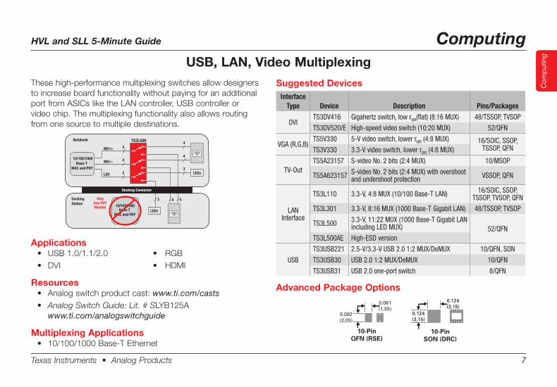
USB, LAN, Video MultiplexingThese high-performance multiplexing switches allow designers to increase board functionality without paying for an additional port from ASICs like the LAN controller, USB controller or video chip. The multiplexing functionality also allows routing from one source to multiple destinations.
Suggested DevicesInterface
Type Device Description Pins/Packages
DVITS3DV416 Gigahertz switch, low ron(flat) (8:16 MUX) 48/TSSOP, TVSOP
TS3DV520/E High-speed video switch (10:20 MUX) 52/QFN
VGA (R,G,B)TS5V330 5-V video switch, lower ron (4:8 MUX) 16/SOIC, SSOP,
TSSOP, QFNTS3V330 3.3-V video switch, lower ron (4:8 MUX)
TV-OutTS5A23157 S-video No. 2 bits (2:4 MUX) 10/MSOP
TS5A623157 S-video No. 2 bits (2:4 MUX) with overshoot and undershoot protection VSSOP, QFN
LANInterface
TS3L110 3.3-V, 4:8 MUX (10/100 Base-T LAN) 16/SOIC, SSOP, TSSOP, TVSOP, QFN
TS3L301 3.3-V, 8:16 MUX (1000 Base-T Gigabit LAN) 48/TSSOP, TVSOP
TS3L500 3.3-V, 11:22 MUX (1000 Base-T Gigabit LAN including LED MUX) 52/QFN
TS3L500AE High-ESD version
USB
TS3USB221 2.5-V/3.3-V USB 2.0 1:2 MUX/DeMUX 10/QFN, SON
TS3USB30 USB 2.0 1:2 MUX/DeMUX 10/QFN
TS3USB31 USB 2.0 one-port switch 8/QFN
10 / 100 / 1000 Base-T
MAC and PHY
Only One PHY Needed
Notebook
Docking Station
MD I+
MD I–
LED
TS3L500 4
4
4
4 4
4
3 3
3
LEDs
LEDs
Docking Connector
10/100/1000
MAC and PHYBase-T
0.061(1,55)
0.082(2,05)
10-PinQFN (RSE)
0.124(3,15)
0.124(3,15)
10-PinSON (DRC)
Advanced Package Options
Applications• USB1.0/1.1/2.0 • RGB• DVI • HDMI
Resources• Analogswitchproductcast:www.ti.com/casts• Analog Switch Guide: Lit. # SLYB125A
www.ti.com/analogswitchguide
Multiplexing Applications• 10/100/1000Base-TEthernet
HVL and SLL 5-Minute Guide Computing
Texas Instruments • Analog Products 8
Com
put
ing
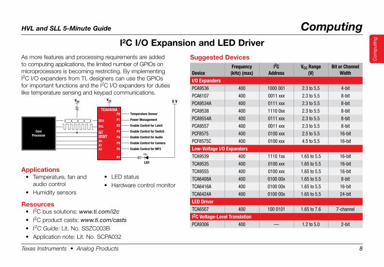
As more features and processing requirements are added to computing applications, the limited number of GPIOs on micro processors is becoming restricting. By implementing I2C I/O expanders from TI, designers can use the GPIOs for important functions and the I2C I/O expanders for duties like temperature sensing and keypad communications.
I2C .I/O .Expansion .and .LED .Driver
Suggested .Devices
DeviceFrequency
(kHz) (max)I2C
AddressVCC Range
(V)Bit or Channel
WidthI/O ExpandersPCA9536 400 1000 001 2.3 to 5.5 4-bit
PCA6107 400 0011 xxx 2.3 to 5.5 8-bit
PCA9534A 400 0111 xxx 2.3 to 5.5 8-bit
PCA9538 400 1110 0xx 2.3 to 5.5 8-bit
PCA9554A 400 0111 xxx 2.3 to 5.5 8-bit
PCA9557 400 0011 xxx 2.3 to 5.5 8-bit
PCF8575 400 0100 xxx 2.5 to 5.5 16-bit
PCF8575C 400 0100 xxx 4.5 to 5.5 16-bit
Low-Voltage I/O ExpandersTCA9539 400 1110 1xx 1.65 to 5.5 16-bit
TCA9535 400 0100 xxx 1.65 to 5.5 16-bit
TCA9555 400 0100 xxx 1.65 to 5.5 16-bit
TCA6408A 400 0100 00x 1.65 to 5.5 8-bit
TCA6416A 400 0100 00x 1.65 to 5.5 16-bit
TCA6424A 400 0100 00x 1.65 to 5.5 24-bit
LED DriverTCA6507 400 100 0101 1.65 to 7.6 7-channel
I2C Voltage-Level TranslationPCA9306 400 — 1.2 to 5.0 2-bit
• LED status• Hardware control monitor
Applications• Temperature, fan and
audio control• Humidity sensors
Resources• I2C bus solutions: www.ti.com/i2c• I2C product casts: www.ti.com/casts• I 2C Guide: Lit. No. SSZC003B• Application note: Lit. No. SCPA032
Vcc Vcc 5 V
SDA
SCL
INT
A0 A1 A2
P0
P1
P2
P3
P4
P5
P6
LED
P7
TCA6408ATemperature Sensor
Power Management
Enable Control for Latch
Enable Control for Switch
Enable Control for Audio
Enable Control for Camera
Enable Control for MP3
RESET
CoreProcessor
HVL and SLL 5-Minute Guide Computing
Texas Instruments • Analog Products 9
Com
put
ing
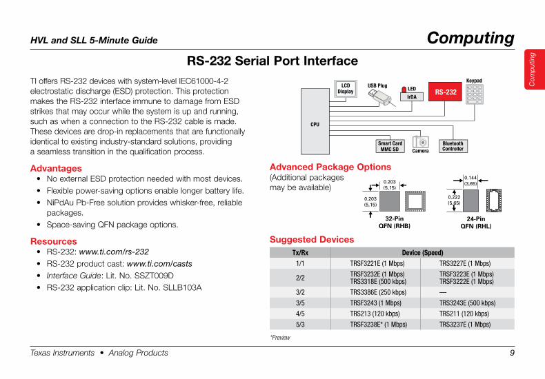
TI offers RS-232 devices with system-level IEC61000-4-2 electrostatic discharge (ESD) protection. This protection makes the RS-232 interface immune to damage from ESD strikes that may occur while the system is up and running, such as when a connection to the RS-232 cable is made. These devices are drop-in replacements that are functionally identical to existing industry-standard solutions, providing a seamless transition in the qualification process.
Advantages• No external ESD protection needed with most devices.• Flexible power-saving options enable longer battery life.• NiPdAu Pb-Free solution provides whisker-free, reliable
packages.• Space-saving QFN package options.
Resources• RS-232: www.ti.com/rs-232• RS-232 product cast: www.ti.com/casts• Interface Guide: Lit. No. SSZT009D• RS-232 application clip: Lit. No. SLLB103A
Smart CardMMC SD
LEDLCD
DisplayUSB Plug
Keypad
CameraBluetoothController
RS-232
CPU
IrDA
RS-232 .Serial .Port .Interface
Suggested .DevicesTx/Rx Device (Speed)
1/1 TRSF3221E (1 Mbps) TRS3227E (1 Mbps)
2/2 TRSF3232E (1 Mbps)TRS3318E (500 kbps)
TRSF3223E (1 Mbps)TRSF3222E (1 Mbps)
3/2 TRS3386E (250 kbps) —
3/5 TRSF3243 (1 Mbps) TRS3243E (500 kbps)
4/5 TRS213 (120 kbps) TRS211 (120 kbps)
5/3 TRSF3238E* (1 Mbps) TRS3237E (1 Mbps)
*Preview
Advanced .Package .Options(Additional packages may be available)
0.203(5,15)
0.203(5,15)
32-PinQFN (RHB)
0.144(3,65)
0.222(5,65)
24-PinQFN (RHL)
HVL and SLL 5-Minute Guide Computing
Texas Instruments • Analog Products 10
Com
put
ing
ESD .Protection
Protected
Circuit
I/O I/O
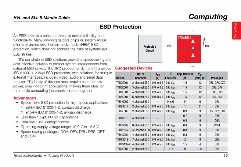
TPDxE001An ESD strike is a constant threat to device reliability and functionality. Many low-voltage core chips or system ASICs offer only device-level human-body model (HBM) ESD protection, which does not address the risks of system-levelESD strikes.
TI's stand-alone ESD solutions provide a space-saving and cost-effective solution to protect system interconnects from external ESD strikes. The TPD product family from TI provides IEC 61000-4-2 level ESD protection, with solutions for multiple external interfaces, including video, audio and serial data transfer. TI's family of devices meet requirements for low- power, small-footprint applications, making them ideal for the mobile computing (notebook) market segment.
Advantages• System-level ESD protection for high-speed applications:
• ±8-kV IEC 61000-4-2, contact discharge.• ±15-kV IEC 61000-4-2, air-gap discharge.
• Less than 1.5-pF I/O pin capacitance.• Ultra-low 1-nA leakage current.• Operating supply voltage range: +0.9 V to +5.5 V.• Space-saving packages: DQA, DRY, DRL, DRS, DRT
and DSM.
Suggested .Devices
DeviceNo. of
ChannelsVDD(V)
I/OLevel (V)
Cap, Resistor(pF)
VBR(min) (V) Packages
TPD2E001 2-channel ESD 0.9 to 5.5 0 to VDD 1.5 12 DRL, DRY, DZD
TPD3E001 3-channel ESD 0.9 to 5.5 0 to VDD 1.5 12 DRL, DRY
TPD4E001 4-channel ESD 0.9 to 5.5 0 to VDD 1.5 12 DRL, DRS
TPD6E001 6-channel ESD 0.9 to 5.5 0 to VDD 1.5 12 RSE, RSF
TPD4E002 4-channel ESD — 0 to 6 11 6 DRL
TPD2S017 2-channel ESD 0.9 to 5.5 0 to VDD 1 11 DBV
TPD2E009 2-channel ESD 0.9 to 5.5 0 to VDD 0.9 9 DBZ, DRY, DRT
0.7 9 DRTTPD4S010 4-channel ESD — 9
0.8 9 DQA
TPD8S009 8-channel ESD 0.9 to 5.5 0 to VDD 0.8 9 DSM
TPD12S521 12-channel ESD 0.9 to 5.5 0 to VDD 0.8 9 DBT
TPD4S009 4-channel ESD 0.9 to 5.5 0 to VDD 0.8 9 DRY
TPD7S019 7-channel ESD 0.9 to 5.5 0 to VDD 2 9 DBQ
TPD4S1394 4-channel ESD 0.9 to 5.5 0 to VDD 1.5 4 DQL
TPD2E007 2-channel ESD — ±14 15 ±14 DCK
HVL and SLL 5-Minute Guide Computing
Texas Instruments • Analog Products 11
Com
put
ing
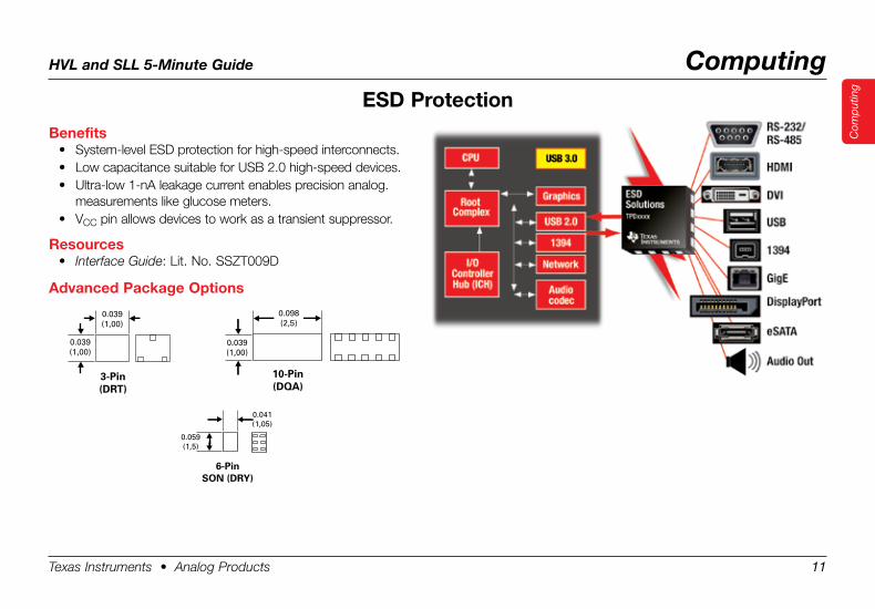
Benefits• System-level ESD protection for high-speed interconnects.• Low capacitance suitable for USB 2.0 high-speed devices.• Ultra-low 1-nA leakage current enables precision analog.
measurements like glucose meters.• VCC pin allows devices to work as a transient suppressor.
Resources• Interface Guide: Lit. No. SSZT009D
Advanced .Package .Options
ESD .Protection
0.041(1,05)
0.059(1,5)
6-Pin SON (DRY)
0.039(1,00)
0.039(1,00)
3-Pin (DRT)
0.098(2,5)
0.039(1,00)
10-Pin (DQA)
Texas Instruments • Analog Products 12
HVL and SLL 5-Minute Guide Notebook
Com
put
ing
Not
eboo
k
Overview
Top .Notebook .Applications .for . .Linear .and .Logic .Devices
• PCI Express® multiplexing• LVDS multiplexing• USB 2.0 switch• HD audio bus translator• ESD protection• ARM® platform netbook• Load switches• LDO voltage regulators
Top .Linear .and .Logic .Device . .Requirements .for .Notebooks
• System .CostAdding even a few pins to an already complex ASIC can increase die size and cost and raise the package price. Specialty switches and I/O expanders can add functionality and features to the board while keeping ASIC costs down.
• Feature .RichnessSpecialty switches allow designers to easily expand board functionality by adding an extra video port, USB port, LAN connection, PCI Express lane or I2C GPIO port to free up processor ports for other functions.
I2C Repeat
LAN Switch
VGA Switch
SDIO-BufferTranslator Super I/O
I2C
HD Audio
ESDProtection
6-BitTranslator
AudioCodec
eSATAConnector
SATAHDD
ControlFunctions
DDR2Memory
DDR2Memory
RS-232Transceiver
GPIOExpanders
SDIO Slots
LAN MAC/PHY
External LVDS
Processor
HDMI/DVISignalSwitch
USB 2.0Switch
ESDProtection
Video DisplayPort
DVIVideo Port
HDMIVideo Port
USB 2.0 Port
USBChargerCircuit
HDMIVideo
Controller MCH
ICH
Dock
ing
Stat
ion
Conn
ectio
n
Prim
ary
Conn
ectio
ns
PCIeSignal Switch
LCDPanel Display
Interface
LVDSSwitch
Texas Instruments • Analog Products 13
HVL and SLL 5-Minute Guide Notebook
Com
put
ing
Not
eboo
k
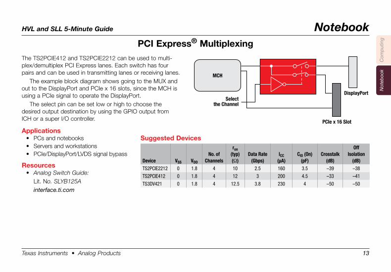
PCI .Express® .MultiplexingThe TS2PCIE412 and TS2PCIE2212 can be used to multi-plex/demultiplex PCI Express lanes. Each switch has four pairs and can be used in transmitting lanes or receiving lanes.
The example block diagram shows going to the MUX and out to the DisplayPort and PCIe x 16 slots, since the MCH is using a PCIe signal to operate the DisplayPort.
The select pin can be set low or high to choose the desired output destination by using the GPIO output from ICH or a super I/O controller.
Applications• PCs and notebooks• Servers and workstations• PCIe/DisplayPort/LVDS signal bypass
Resources• Analog Switch Guide: Lit. No. SLYB125A interface.ti.com
MCH
Selectthe Channel
PCIe x 16 Slot
DisplayPort
Suggested .Devices
Device VSS VDD
No. of Channels
ron(typ)(Ω)
Data Rate(Gbps)
ICC(µA)
CIO (On)(pF)
Crosstalk(dB)
OffIsolation
(dB)TS2PCIE2212 0 1.8 4 10 2.5 160 3.5 –39 –38
TS2PCIE412 0 1.8 4 12 3 200 4.5 –33 –41
TS3DV421 0 1.8 4 12.5 3.8 230 4 –50 –50
Texas Instruments • Analog Products 14
HVL and SLL 5-Minute Guide Notebook
Com
put
ing
Not
eboo
k
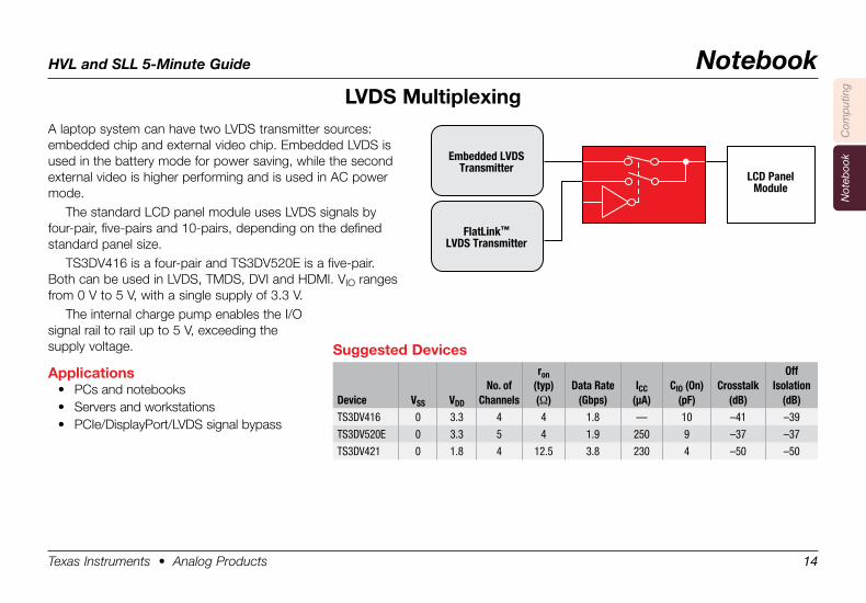
LVDS .MultiplexingA laptop system can have two LVDS transmitter sources: embedded chip and external video chip. Embedded LVDS is used in the battery mode for power saving, while the second external video is higher performing and is used in AC power mode.
The standard LCD panel module uses LVDS signals by four-pair, five-pairs and 10-pairs, depending on the defined standard panel size.
TS3DV416 is a four-pair and TS3DV520E is a five-pair. Both can be used in LVDS, TMDS, DVI and HDMI. VIO ranges from 0 V to 5 V, with a single supply of 3.3 V.
The internal charge pump enables the I/O signal rail to rail up to 5 V, exceeding the supply voltage.
Applications• PCs and notebooks• Servers and workstations• PCIe/DisplayPort/LVDS signal bypass
Suggested .Devices
Device VSS VDD
No. of Channels
ron(typ)(Ω)
Data Rate(Gbps)
ICC(µA)
CIO (On)(pF)
Crosstalk(dB)
OffIsolation
(dB)TS3DV416 0 3.3 4 4 1.8 — 10 –41 –39
TS3DV520E 0 3.3 5 4 1.9 250 9 –37 –37
TS3DV421 0 1.8 4 12.5 3.8 230 4 –50 –50
Embedded LVDSTransmitter
FlatLink™
LVDS Transmitter
LCD PanelModule
Texas Instruments • Analog Products 15
HVL and SLL 5-Minute Guide Notebook
Com
put
ing
Not
eboo
k
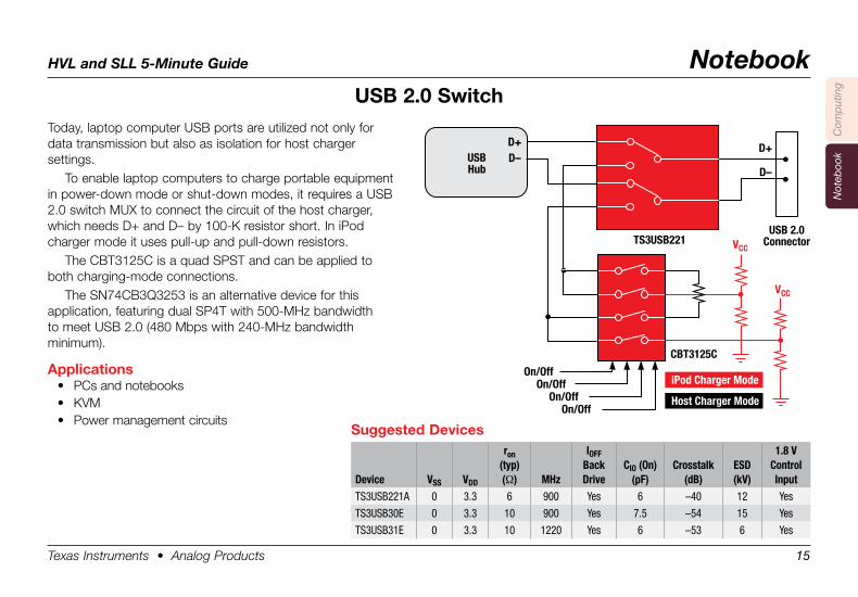
USB .2 .0 .SwitchToday, laptop computer USB ports are utilized not only for data transmission but also as isolation for host charger settings.
To enable laptop computers to charge portable equipment in power-down mode or shut-down modes, it requires a USB 2.0 switch MUX to connect the circuit of the host charger, which needs D+ and D– by 100-K resistor short. In iPod charger mode it uses pull-up and pull-down resistors.
The CBT3125C is a quad SPST and can be applied to both charging-mode connections.
The SN74CB3Q3253 is an alternative device for this application, featuring dual SP4T with 500-MHz bandwidth to meet USB 2.0 (480 Mbps with 240-MHz bandwidth minimum).
Applications• PCs and notebooks• KVM• Power management circuits
Suggested .Devices
Device VSS VDD
ron(typ)(Ω) MHz
IOFFBackDrive
CIO (On)(pF)
Crosstalk(dB)
ESD(kV)
1.8 VControlInput
TS3USB221A 0 3.3 6 900 Yes 6 –40 12 Yes
TS3USB30E 0 3.3 10 900 Yes 7.5 –54 15 Yes
TS3USB31E 0 3.3 10 1220 Yes 6 –53 6 Yes
VCC
VCC
USBHub
D+D–
D+
D–
USB 2.0ConnectorTS3USB221
CBT3125C
On/OffOn/Off
On/OffOn/Off
iPod Charger Mode
Host Charger Mode
Texas Instruments • Analog Products 16
HVL and SLL 5-Minute Guide Notebook
Com
put
ing
Not
eboo
k
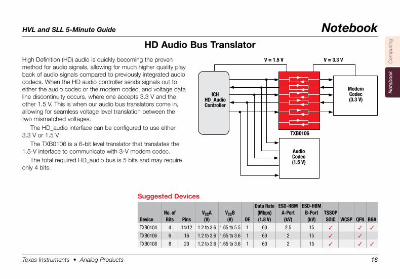
HD .Audio .Bus .TranslatorHigh Definition (HD) audio is quickly becoming the proven method for audio signals, allowing for much higher quality play back of audio signals compared to previously integrated audio codecs. When the HD audio controller sends signals out to either the audio codec or the modem codec, and voltage data line discontinuity occurs, where one accepts 3.3 V and the other 1.5 V. This is when our audio bus translators come in, allowing for seamless voltage level translation between the two mismatched voltages.
The HD_audio interface can be configured to use either 3.3 V or 1.5 V.
The TXB0106 is a 6-bit level translator that translates the 1.5-V interface to communicate with 3-V modem codec.
The total required HD_audio bus is 5 bits and may require only 4 bits.
Suggested .Devices
DeviceNo. of Bits Pins
VCCA(V)
VCCB(V) OE
Data Rate(Mbps)(1.8 V)
ESD-HBMA-Port(kV)
ESD-HBMB-Port(kV)
TSSOP SOIC WCSP QFN BGA
TXB0104 4 14/12 1.2 to 3.6 1.65 to 5.5 1 60 2.5 15 3 3 3
TXB0106 6 16 1.2 to 3.6 1.65 to 3.6 1 60 2 15 3 3
TXB0108 8 20 1.2 to 3.6 1.65 to 3.6 1 60 2 15 3 3 3
ICHHD_AudioController
ModemCodec(3.3 V)
V = 3.3 VV = 1.5 V
TXB0106
AudioCodec(1.5 V)
Texas Instruments • Analog Products 17
HVL and SLL 5-Minute Guide Notebook
Com
put
ing
Not
eboo
k
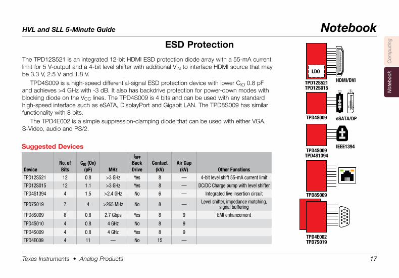
ESD .ProtectionThe TPD12S521 is an integrated 12-bit HDMI ESD protection diode array with a 55-mA current limit for 5 V-output and a 4-bit level shifter with additional VIN to interface HDMI source that may be 3.3 V, 2.5 V and 1.8 V.
TPD4S009 is a high-speed differential-signal ESD protection device with lower CIO 0.8 pF and achieves >4 GHz with -3 dB. It also has backdrive protection for power-down modes with blocking diode on the VCC lines. The TPD4S009 is 4 bits and can be used with any standard high-speed interface such as eSATA, DisplayPort and Gigabit LAN. The TPD8S009 has similar functionality with 8 bits.
The TPD4E002 is a simple suppression-clamping diode that can be used with either VGA, S-Video, audio and PS/2.
Suggested .Devices
DeviceNo. of Bits
CIO (On)(pF) MHz
IOFFBackDrive
Contact(kV)
Air Gap(kV) Other Functions
TPD12S521 12 0.8 >3 GHz Yes 8 — 4-bit level shift 55-mA current limit
TPD12S015 12 1.1 >3 GHz Yes 8 — DC/DC Charge pump with level shifter
TPD4S1394 4 1.5 >2.4 GHz No 6 — Integrated live insertion circuit
TPD7S019 7 4 >265 MHz No 8 — Level shifter, impedance matching, signal buffering
TPD8S009 8 0.8 2.7 Gbps Yes 8 9 EMI enhancement
TPD4S010 4 0.8 4 GHz No 8 9
TPD4S009 4 0.8 4 GHz Yes 8 9
TPD4E009 4 11 — No 15 —
19
17
15
13
11
97
53
18
16
14
12
10
86
42
1
LDO
TPD12S521TPD12S015
TPD4S009
TPD4S009TPD4S1394
IEEE1394
eSATA/DP
HDMI/DVI
TPD8S009
TPD4E002TPD7S019
24
68
1012
1416
1820
13
57
911
1315
1719
Texas Instruments • Analog Products 18
HVL and SLL 5-Minute Guide Notebook
Com
put
ing
Not
eboo
k
ARM® .Platform .Netbook
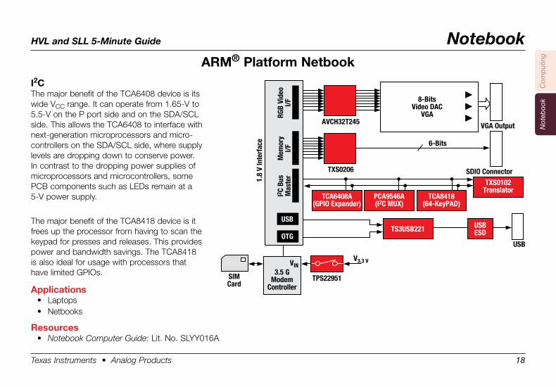
I2CThe major benefit of the TCA6408 device is its wide VCC range. It can operate from 1.65-V to 5.5-V on the P port side and on the SDA/SCL side. This allows the TCA6408 to interface with next-generation microprocessors and micro- controllers on the SDA/SCL side, where supply levels are dropping down to conserve power. In contrast to the dropping power supplies of microprocessors and microcontrollers, some PCB components such as LEDs remain at a 5-V power supply.
The major benefit of the TCA8418 device is it frees up the processor from having to scan the keypad for presses and releases. This provides power and bandwidth savings. The TCA8418 is also ideal for usage with processors that have limited GPIOs.
Applications• Laptops • Netbooks
Resources• Notebook Computer Guide: Lit. No. SLYY016A
TXS0206
3.5 GModem
ControllerRG
B Vi
deo
I/F
VINV3.3 V
TPS22951SIMCard
AVCH32T245
8-BitsVideo DAC
VGA
VGA Output
6-Bits
USB
SDIO Connector
USB
OTG
Mem
ory
I/FI2
C Bu
sM
aste
r1.8
V In
terf
ace
TCA8418(64-KeyPAD)
TXS0102Translator
TS3USB221 USBESD
PCA9546A(I2C MUX)
TCA6408A(GPIO Expander)
Texas Instruments • Analog Products 19
HVL and SLL 5-Minute Guide Notebook
Com
put
ing
Not
eboo
k
ARM® .Platform .Netbook
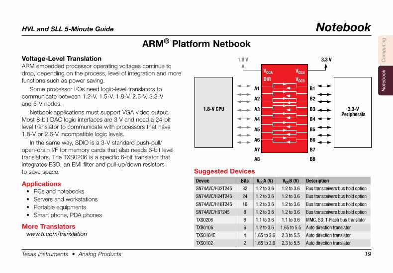
Voltage-Level .TranslationARM embedded processor operating voltages continue to drop, depending on the process, level of integration and more functions such as power saving.
Some processor I/Os need logic-level translators to communicate between 1.2-V, 1.5-V, 1.8-V, 2.5-V, 3.3-V and 5-V nodes.
Netbook applications must support VGA video output. Most 8-bit DAC logic interfaces are 3 V and need a 24-bit level translator to communicate with processors that have 1.8-V or 2.6-V incompatible logic levels.
In the same way, SDIO is a 3-V standard push-pull/ open-drain I/F for memory cards that also needs 6-bit level translators. The TXS0206 is a specific 6-bit translator that integrates ESD, an EMI filter and pull-up/down resistors to save space.
Applications• PCs and notebooks• Servers and workstations• Portable equipments• Smart phone, PDA phones
More .Translatorswww.ti.com/translation
Suggested .DevicesDevice Bits VCCA (V) VCCB (V) DescriptionSN74AVC/H32T245 32 1.2 to 3.6 1.2 to 3.6 Bus transceivers bus hold option
SN74AVC/H24T245 24 1.2 to 3.6 1.2 to 3.6 Bus transceivers bus hold option
SN74AVC/H16T245 16 1.2 to 3.6 1.2 to 3.6 Bus transceivers bus hold option
SN74AVC/H8T245 8 1.2 to 3.6 1.2 to 3.6 Bus transceivers bus hold option
TXS0206 6 1.1 to 3.6 1.1 to 3.6 MMC, SD, T-Flash bus translator
TXB0106 6 1.2 to 3.6 1.65 to 5.5 Auto direction translator
TXS0104E 4 1.65 to 3.6 2.3 to 5.5 Auto direction translator
TXS0102 2 1.65 to 3.6 2.3 to 5.5 Auto direction translator
A1
1.8-V CPU 3.3-VPeripherals
3.3 V1.8 V
A2
A3
A4
A5
A6
A7
A8
B1
B2
B3
B4
B5
B6
B7
B8
VCCA
DIR
VCCB
VCCB
Texas Instruments • Analog Products 20
HVL and SLL 5-Minute Guide Notebook
Com
put
ing
Not
eboo
k
ARM® .Platform .Netbook
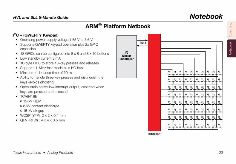
I2C .– .(QWERTY .Keypad)• Operating power supply voltage 1.65 V to 3.6 V• Supports QWERTY keypad operation plus 2x GPIO
expansion• 18 GPIOs can be configured into 8 x 8 and 8 x 10 buttons• Low standby current 3 mA• 10-byte FIFO to store 10-key presses and releases• Supports 1-MHz fast mode plus I2C bus• Minimum debounce time of 50 m • Ability to handle three key presses and distinguish the keys (avoids ghosting)• Open-drain active-low interrupt output, asserted when keys are pressed and released• TCA8418E • 15-kV HBM • 8-kV contact discharge • 15-kV air gap• WCSP (YFP): 2 x 2 x 0.4 mm• QFN (RTW) : 4 x 4 x 0.5 mm
I2CMaster
µController
SC1A
X0
TCA8418/E
X0 X0 X0 X0 X0 X0 X0 X0 X0
X1 X1 X1 X1 X1 X1 X1 X1 X1 X1
X2 X2 X2 X2 X2 X2 X2 X2 X2 X2
X3 X3 X3 X3 X3 X3 X3 X3 X3 X3
X4 X4 X4 X4 X4 X4 X4 X4 X4 X4
X5 X5 X5 X5 X5 X5 X5 X5 X5 X5
X6 X6 X6 X6 X6 X6 X6 X6 X6 X6
X7 X7 X7 X7 X7 X7 X7 X7 X7 X7
Texas Instruments • Analog Products 21
HVL and SLL 5-Minute Guide Notebook
Com
put
ing
Not
eboo
k
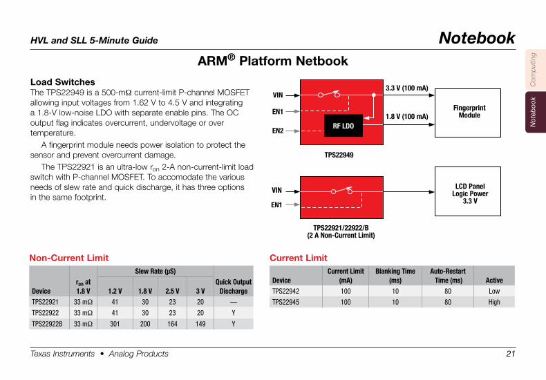
Non-Current .LimitSlew Rate (µS)
Deviceron at 1.8 V 1.2 V 1.8 V 2.5 V 3 V
Quick Output Discharge
TPS22921 33 mΩ 41 30 23 20 —
TPS22922 33 mΩ 41 30 23 20 Y
TPS22922B 33 mΩ 301 200 164 149 Y
Current .Limit
DeviceCurrent Limit
(mA)Blanking Time
(ms)Auto-Restart Time (ms) Active
TPS22942 100 10 80 Low
TPS22945 100 10 80 High
VIN3.3 V (100 mA)
1.8 V (100 mA)
TPS22949
TPS22921/22922/B(2 A Non-Current Limit)
EN1
VIN
EN1
EN2
FingerprintModule
LCD PanelLogic Power
3.3 V
RF LDO
Load .SwitchesThe TPS22949 is a 500-mΩ current-limit P-channel MOSFET allowing input voltages from 1.62 V to 4.5 V and integrating a 1.8-V low-noise LDO with separate enable pins. The OC output flag indicates overcurrent, undervoltage or over temperature.
A fingerprint module needs power isolation to protect the sensor and prevent overcurrent damage.
The TPS22921 is an ultra-low ron 2-A non-current-limit load switch with P-channel MOSFET. To accomodate the various needs of slew rate and quick discharge, it has three options in the same footprint.
ARM® .Platform .Netbook
Texas Instruments • Analog Products 22
HVL and SLL 5-Minute Guide Notebook
Com
put
ing
Not
eboo
k
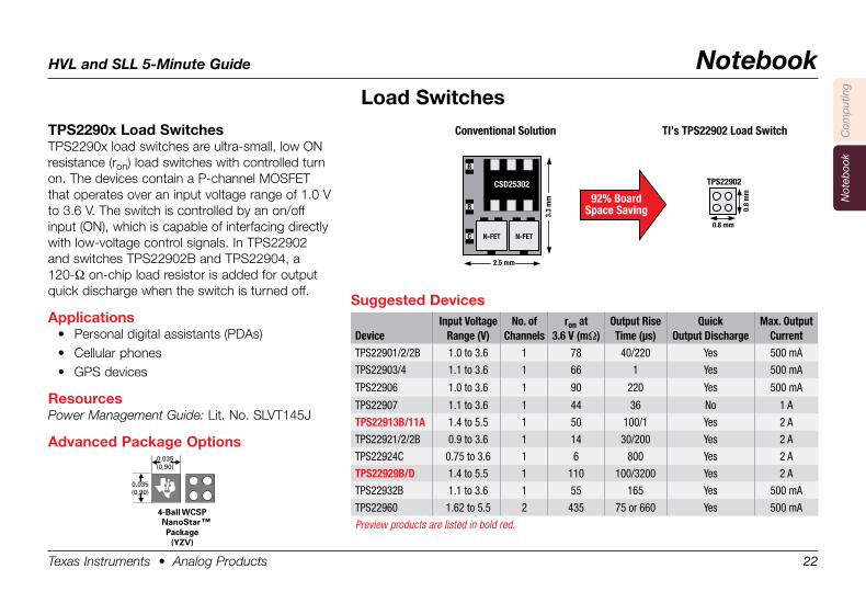
TPS2290x .Load .SwitchesTPS2290x load switches are ultra-small, low ON resistance (ron) load switches with controlled turn on. The devices contain a P-channel MOSFET that operates over an input voltage range of 1.0 V to 3.6 V. The switch is controlled by an on/off input (ON), which is capable of interfacing directly with low-voltage control signals. In TPS22902 and switches TPS22902B and TPS22904, a 120-Ω on-chip load resistor is added for output quick discharge when the switch is turned off.
Applications• Personal digital assistants (PDAs)• Cellular phones• GPS devices
ResourcesPower Management Guide: Lit. No. SLVT145J
Advanced .Package .Options
Suggested .Devices
DeviceInput Voltage
Range (V)No. of
Channelsron at
3.6 V (mΩ)Output Rise Time (µs)
Quick Output Discharge
Max. Output Current
TPS22901/2/2B 1.0 to 3.6 1 78 40/220 Yes 500 mA
TPS22903/4 1.1 to 3.6 1 66 1 Yes 500 mA
TPS22906 1.0 to 3.6 1 90 220 Yes 500 mA
TPS22907 1.1 to 3.6 1 44 36 No 1 A
TPS22913B/11A 1.4 to 5.5 1 50 100/1 Yes 2 A
TPS22921/2/2B 0.9 to 3.6 1 14 30/200 Yes 2 A
TPS22924C 0.75 to 3.6 1 6 800 Yes 2 A
TPS22929B/D 1.4 to 5.5 1 110 100/3200 Yes 2 A
TPS22932B 1.1 to 3.6 1 55 165 Yes 500 mA
TPS22960 1.62 to 5.5 2 435 75 or 660 Yes 500 mA
Preview products are listed in bold red.
Load .Switches
Ball Pitch = 0.020 (0,50)Height = 0.020 (0,50)Area = 0.001 (0,65)
4-Ball WCSPNanoStar Package
(YZV)
0.035(0,90)
0.035(0,90)
™
Conventional Solution TI’s TPS22902 Load Switch
92% BoardSpace Saving
2.5 mm
N-FET
3.3
mm
N-FET
R
R
CSD25302
C
0.8 mm
TPS22902
0.8
mm
Texas Instruments • Analog Products 23
HVL and SLL 5-Minute Guide Notebook
Com
put
ing
Not
eboo
k
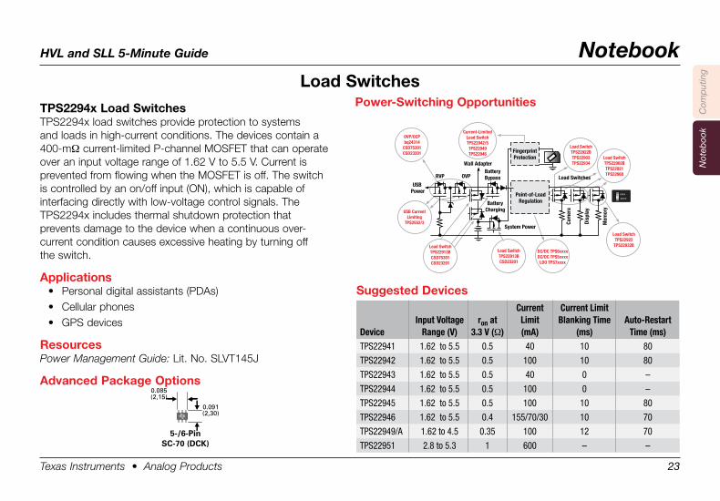
TPS2294x .Load .SwitchesTPS2294x load switches provide protection to systems and loads in high-current conditions. The devices contain a 400-mΩ current-limited P-channel MOSFET that can operate over an input voltage range of 1.62 V to 5.5 V. Current is prevented from flowing when the MOSFET is off. The switch is controlled by an on/off input (ON), which is capable of interfacing directly with low-voltage control signals. The TPS2294x includes thermal shutdown protection that prevents damage to the device when a continuous over- current condition causes excessive heating by turning off the switch.
Applications• Personal digital assistants (PDAs)• Cellular phones• GPS devices
ResourcesPower Management Guide: Lit. No. SLVT145J
Advanced .Package .Options
Suggested .Devices
DeviceInput Voltage
Range (V)ron at
3.3 V (Ω)
Current Limit (mA)
Current Limit Blanking Time
(ms)Auto-Restart
Time (ms)TPS22941 1.62 to 5.5 0.5 40 10 80
TPS22942 1.62 to 5.5 0.5 100 10 80
TPS22943 1.62 to 5.5 0.5 40 0 –
TPS22944 1.62 to 5.5 0.5 100 0 –
TPS22945 1.62 to 5.5 0.5 100 10 80
TPS22946 1.62 to 5.5 0.4 155/70/30 10 70
TPS22949/A 1.62 to 4.5 0.35 100 12 70
TPS22951 2.8 to 5.3 1 600 – –
Load .Switches
FingerprintProtection
USB Power
System Power
BatteryCharging
Point-of-LoadRegulation
Cam
era
Disp
lay
Mem
ory
BatteryBypassRVP OVP
OVP/OCPbq24314
CSD75301CSD23201
Wall Adapter
Power-Switching Opportunities
Load SwitchTPS22922BTPS22903TPS22934
Load SwitchTPS22902BTPS22921TPS22960
Load SwitchTPS22922
TPS22932B
Current-LimitedLoad SwitchTPS22942/5TPS22949TPS22946
DC/DC TPS6xxxxDC/DC TPS5xxxx
LDO TPS7xxxx
Load SwitchTPS22913BCSD23201
USB CurrentLimiting
TPS2552/3
Load SwitchTPS22913BCSD75301CSD23201
Load Switches
Power-Switching .Opportunities
0.085(2,15)
0.091(2,30)
5-/6-PinSC-70 (DCK)
Texas Instruments • Analog Products 24
HVL and SLL 5-Minute Guide Notebook
Com
put
ing
Not
eboo
k
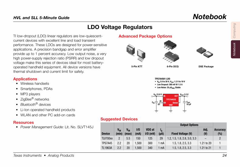
TI low-dropout (LDO) linear regulators are low-quiescent- current devices with excellent line and load transient performance. These LDOs are designed for power-sensitive applications. A precision bandgap and error amplifier provide up to 1 percent accuracy. Low output noise, a very high power-supply rejection ratio (PSRR) and low dropout voltage make this series of devices ideal for most battery-operated handheld equipment. All device versions have thermal shutdown and current limit for safety.
Applications• Wireless handsets• Smartphones, PDAs• MP3 players• ZigBee® networks• Bluetooth® devices• Li-Ion operated handheld products• WLAN and other PC add-on cards
Resources• Power Management Guide: Lit. No. SLVT145J
LDO .Voltage .Regulators
Suggested .DevicesOutput Options
DeviceVIN
(min)VIN
(max)I/O
(mA)VDO at
I/O (mV)lq
(µA) Fixed Voltage (V)Adj. (V)
Accuracy (%)
TLV700xx 2 5.5 150 125 29 1.2, 1.5, 1.8, 2.8, 3.0, 3.3 – 2
TPS7A45 2.2 20 1,500 300 1 mA 1.5, 1.8, 2.5, 3.3 1.21 to 20 1
TL1963A 2.2 20 1,500 340 1 mA 1.5, 1.8, 2.5, 3.3 1.21 to 21 1
COUT10 µF
CIN
VIN 12.0 V VOUT 3.3 V
TPS7A4501 LDO• VIN 2.0 to 20 V, VOUT 1.2 V to 19 V• Low Dropout: 300 mV @ 1.5 A• Low Noise: 35 µVRMS Stable
ON
OFF
IN
EN
OUT
TPS7A4533
SenseGND
Advanced .Package .Options
5-Pin .KTT 6-Pin .DCQ DSE .Package
HVL and SLL 5-Minute Guide Server/Storage
Texas Instruments • Analog Products 25
Com
put
ing
Not
eboo
kS
erve
r/S
tora
ge
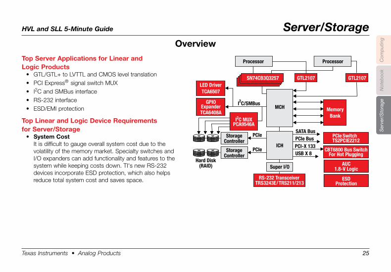
Top .Server .Applications .for .Linear .and . .Logic .Products
• GTL/GTL+ to LVTTL and CMOS level translation• PCI Express® signal switch MUX• I2C and SMBus interface• RS-232 interface• ESD/EMI protection
Top .Linear .and .Logic .Device .Requirements .for .Server/Storage
• System .CostIt is difficult to gauge overall system cost due to the volatility of the memory market. Specialty switches and I/O expanders can add functionality and features to the system while keeping costs down. TI's new RS-232 devices incorporate ESD protection, which also helps reduce total system cost and saves space.
Overview
GPIOExpanderTCA6408A
LED DriverTCA6507
PCIe SwitchTS2PCIE2212
CBT6800 Bus SwitchFor Hot Plugging
AUC1.8-V Logic
ESDProtection
I C/SMBus2
PCIe
PCIe
StorageController
StorageController
Hard Disk(RAID)
MCH
ICH
SATA Bus
MemoryBank
PCIe BusPCI-X 133USB X 8
RS-232 TransceiverTRS3243E/TRS211/213
Super I/O
GTL2107GTL2107
Processor
SN74CB3Q3257
Processor
I C MUX2
PCA9546A
HVL and SLL 5-Minute Guide Server/Storage
Texas Instruments • Analog Products 26
Com
put
ing
Not
eboo
kS
erve
r/S
tora
ge
Overview
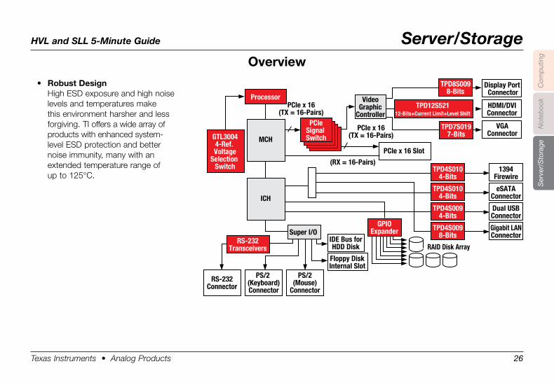
• Robust .DesignHigh ESD exposure and high noise levels and temperatures make this environment harsher and less forgiving. TI offers a wide array of products with enhanced system- level ESD protection and better noise immunity, many with an extended temperature range of up to 125°C.
Super I/O
PCIeSignal SwitchGTL3004
4-Ref. Voltage
Selection Switch TPD4S010
4-Bits
TPD8S0098-Bits
TPD12S52112-Bits+Current Limit+Level Shift
GPIOExpander
RS-232Transceivers
IDE Bus forHDD Disk
Floppy DiskInternal Slot
1394Firewire
TPD4S0104-Bits
eSATAConnector
TPD4S0094-Bits
Dual USBConnector
Display Port Connector
HDMI/DVIConnector
VGAConnector
TPD4S0098-Bits
Gigabit LANConnector
RAID Disk Array
PS/2(Mouse)
Connector
PS/2 (Keyboard)Connector
RS-232Connector
Processor
MCH
PCIe x 16(TX = 16-Pairs)
PCIe x 16(TX = 16-Pairs)
(RX = 16-Pairs)
ICH
PCIe x 16 Slot
TPD7S0197-Bits
VideoGraphic
Controller
HVL and SLL 5-Minute Guide Server/Storage
Texas Instruments • Analog Products 27
Com
put
ing
Not
eboo
kS
erve
r/S
tora
ge
Desktop/Server
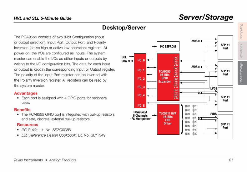
The PCA9555 consists of two 8-bit Configuration (input or output selection), Input Port, Output Port, and Polarity Inversion (active high or active low operation) registers. At power on, the I/Os are configured as inputs. The system master can enable the I/Os as either inputs or outputs by writing to the I/O configuration bits. The data for each input or output is kept in the corresponding Input or Output register. The polarity of the Input Port register can be inverted with the Polarity Inversion register. All registers can be read by the system master.
Advantages• Each port is assigned with 4 GPIO ports for peripheral
uses.
Benefits• The PCA9555 GPIO port is integrated with pull-up resistors
and safe, discrete, external pull-up resistors.
Resources• I2C Guide: Lit. No. SSZC003B• LED Reference Design Cookbook: Lit. No. SLYT349
I2C EEPROM
SCLSCA
PCA9548A8 Channels
12C Multiplexer
SFP #1Port
LVDS
SFP #1Port
SFP #1Port
SFP #1Port
TCA955516-Bits
GPIOExpander
P0P1P2P3
TLC591116/F16-Bits
LEDDriver
I2C_0
I2C_1
I2C_2
I2C_3
I2C_4
I2C_5
LVDS
LVDS
LVDS
P4P5P6P7
P8P9
P10P11
P12P13P14P15
HVL and SLL 5-Minute Guide Server/Storage
Texas Instruments • Analog Products 28
Com
put
ing
Not
eboo
kS
erve
r/S
tora
ge
Desktop/Server
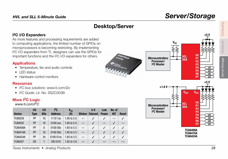
I2C .I/O .ExpandersAs more features and processing requirements are added to computing applications, the limited number of GPIOs on microprocessors is becoming restricting. By implementing I2C I/O expanders from TI, designers can use the GPIOs for important functions and the I2C I/O expanders for others.
Applications• Temperature, fan and audio controls• LED status• Hardware control monitors
Resources• I2C bus solutions: www.ti.com/i2c• I2C Guide: Lit. No. SSZC003B
More .I2C .Logicwww.ti.com/I2C
MicrocontrollersProcessor/I2C Master
VCC
+5 V
P0P1P2P3P4P5P6P7
SCLSDA
I/OI/OI/OI/O
MicrocontrollersProcessor/I2C Master
+1.8 V
TCA6408ATCA6416ATCA6424A
+5 V
P0P1P2P3P4P5P6P7
SCLSDA
I/OI/OI/OI/O
VCCI VCCI
DeviceI/O
TypeI/OBits
I2C Address
VCC (V) Blinker
5-VTolerant
Low Power
No. of INT Reset
TCA9539 PP 16 1110 1xx 1.65 to 5.5 — 3 3 — 3
TCA9555 PP 16 0100 xxx 1.65 to 5.5 — 3 — 3 —
TCA6408A PP 8 0100 00x 1.65 to 5.5 — 3 3 3 3
TCA6416A PP 16 0100 00x 1.65 to 5.5 — 3 3 3 3
TCA6424A PP 24 0100 01xx 1.65 to 5.5 — 3 3 3 3
TCA6507 OD 7 100 0101 1.65 to 3.6 — 3 — — —
HVL and SLL 5-Minute Guide Server/Storage
Texas Instruments • Analog Products 29
Com
put
ing
Not
eboo
kS
erve
r/S
tora
ge
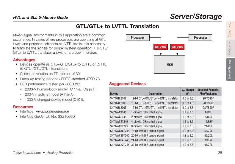
GTL/GTL+ to LVTTL TranslationMixed-signal environments in this application are a common occurrence. In cases where processors are operating at GTL levels and peripheral chipsets at LVTTL levels, it is necessary to translate the signals for proper system operation. TI’s GTL/GTL+ to LVTTL translator allows for a proper interface.
Advantages• DevicesoperateasGTL–/GTL/GTL+toLVTTLorLVTTL
toGTL–/GTL/GTL+translators.• SeriesterminationonTTLoutputof30.• Latch-uptestingdonetoJEDECstandardJESD78.• ESDperformancetestedperJESD22:
• 2000-Vhuman-bodymodel(A114-B,ClassII).• 200-Vmachinemodel(A115-A).• 1000-Vcharged-devicemodel(C101).
Resources• Interface:www.ti.com/interface• Interface Guide: Lit. No. SSZT009D
Device DescriptionVCC Range
(V)Smallest Footprint
Pins/PackagesSN74GTL2107 12-bit GTL–/GTL/GTL+ to LVTTL translator 3.0 to 3.3 28/TSSOP
SN74GTL2006 13-bit GTL–/GTL/GTL+ to LVTTL translator 0.5 to 4.6 28/TSSOP
SN74GTL2007 12-bit GTL–/GTL/GTL+ to LVTTL translator 3.0 to 3.6 28/TSSOP
SN74AVC1T45 1-bit with DIR control signal 1.2 to 3.6 6/DRL
SN74AVC2T45 2-bit with DIR control signal 1.2 to 3.6 8/DCU
SN74AVC4T245 4-bit with DIR control signal 1.2 to 3.6 16/RSV
SN74AVC8T245 8-bit with DIR control signal 1.2 to 3.6 24/RHL
SN74AVC16T245 16-bit with DIR control signal 1.2 to 3.6 56/ZQL
SN74AVC20T245 20-bit with DIR control signal 1.2 to 3.6 56/ZQL
SN74AVC24T245 24-bit with DIR control signal 1.2 to 3.6 83/RG
SN74AVC32T245 32-bit with DIR control signal 1.2 to 3.6 96/ZRL
GTL2107
Processor
GTL2107
Processor
MCH
Suggested Devices
HVL and SLL 5-Minute Guide Server/Storage
Texas Instruments • Analog Products 30
Com
put
ing
Not
eboo
kS
erve
r/S
tora
ge
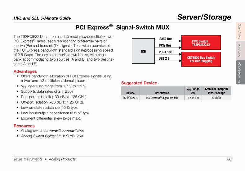
PCI .Express® . .Signal-Switch .MUXThe TS2PCIE2212 can be used to muxltiplex/demultiplex two PCI Express® lanes, each representing differential pairs of receive (Rx) and transmit (Tx) signals. The switch operates at the PCI Express bandwidth standard signal-processing speed of 2.5 Gbps. The device comprises two banks, with each bank accommodating two sources (A and B) and two destina-tions (A and B).
Advantages• Offers bandwidth allocation of PCI Express signals using
a two-lane 1:2 multiplexer/demultiplexer.• VCC operating range from 1.7 V to 1.9 V.• Supports data rates of 2.5 Gbps.• Port-port crosstalk (–39 dB at 1.25 GHz).• Off-port isolation (–38 dB at 1.25 GHz).• Low on-state resistance (10 Ω typ).• Low input/output capacitance (3.5-pF typ).• Excellent differential skew (5-ps max).
Resources• Analog switches: www.ti.com/switches• Analog Switch Guide: Lit. # SLYB125A
PCIe SwitchTS2PCIE2212
CBT6800 Bus SwitchFor Hot Plugging
ICH
SATA Bus
PCIe Bus
PCI-X 133
USB X 8
Suggested .Device
Device DescriptionVCC Range
(V)Smallest Footprint
Pins/PackageTS2PCIE2212 PCI Express® signal switch 1.7 to 1.9 48/BGA
HVL and SLL 5-Minute Guide Server/Storage
Texas Instruments • Analog Products 31
Com
put
ing
Not
eboo
kS
erve
r/S
tora
ge
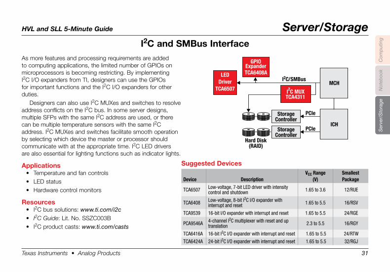
I2C .and .SMBus .InterfaceAs more features and processing requirements are added to computing applications, the limited number of GPIOs on microprocessors is becoming restricting. By implementing I2C I/O expanders from TI, designers can use the GPIOs for important functions and the I2C I/O expanders for other duties.
Designers can also use I2C MUXes and switches to resolve address conflicts on the I2C bus. In some server designs, multiple SFPs with the same I2C address are used, or there can be multiple temperature sensors with the same I2C address. I2C MUXes and switches facilitate smooth operation by selecting which device the master or processor should communicate with at the appropriate time. I2C LED drivers are also essential for lighting functions such as indicator lights.
Applications• Temperature and fan controls• LED status• Hardware control monitors
Resources• I2C bus solutions: www.ti.com/i2c• I2C Guide: Lit. No. SSZC003B• I2C product casts: www.ti.com/casts
GPIOExpanderTCA6408A
I C/SMBus2
PCIe
PCIe
StorageController
StorageController
Hard Disk(RAID)
MCH
ICH
LEDDriver
TCA6507 I C MUX2
TCA4311
Suggested .Devices
Device DescriptionVCC Range
(V)SmallestPackage
TCA6507 Low-voltage, 7-bit LED driver with intensity control and shutdown 1.65 to 3.6 12/RUE
TCA6408 Low-voltage, 8-bit I2C I/O expander with interrupt and reset 1.65 to 5.5 16/RSV
TCA9539 16-bit I/O expander with interrupt and reset 1.65 to 5.5 24/RGE
PCA9546A 4-channel I2C multiplexer with reset and up translation 2.3 to 5.5 16/RGY
TCA6416A 16-bit I2C I/O expander with interrupt and reset 1.65 to 5.5 24/RTW
TCA6424A 24-bit I2C I/O expander with interrupt and reset 1.65 to 5.5 32/RGJ
HVL and SLL 5-Minute Guide Server/Storage
Texas Instruments • Analog Products 32
Com
put
ing
Not
eboo
kS
erve
r/S
tora
ge
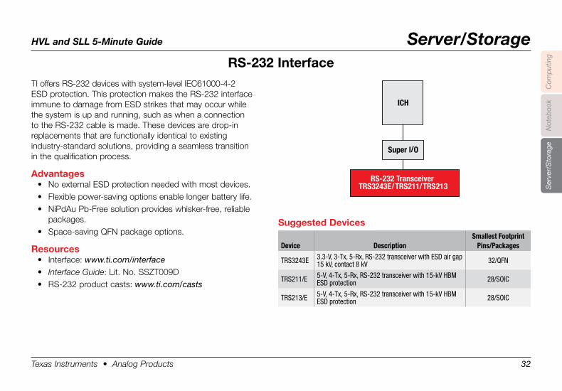
RS-232 .InterfaceTI offers RS-232 devices with system-level IEC61000-4-2 ESD protection. This protection makes the RS-232 interface immune to damage from ESD strikes that may occur while the system is up and running, such as when a connection to the RS-232 cable is made. These devices are drop-in replacements that are functionally identical to existing industry-standard solutions, providing a seamless transition in the qualification process.
Advantages• No external ESD protection needed with most devices.• Flexible power-saving options enable longer battery life.• NiPdAu Pb-Free solution provides whisker-free, reliable
packages.• Space-saving QFN package options.
Resources• Interface: www.ti.com/interface• Interface Guide: Lit. No. SSZT009D• RS-232 product casts: www.ti.com/casts
RS-232 Transceiver
TRS3243E/TRS211/TRS213
ICH
Super I/O
Suggested .Devices
Device DescriptionSmallest Footprint
Pins/Packages
TRS3243E 3.3-V, 3-Tx, 5-Rx, RS-232 transceiver with ESD air gap 15 kV, contact 8 kV 32/QFN
TRS211/E 5-V, 4-Tx, 5-Rx, RS-232 transceiver with 15-kV HBM ESD protection 28/SOIC
TRS213/E 5-V, 4-Tx, 5-Rx, RS-232 transceiver with 15-kV HBM ESD protection 28/SOIC
HVL and SLL 5-Minute Guide Server/Storage
Texas Instruments • Analog Products 33
Com
put
ing
Not
eboo
kS
erve
r/S
tora
ge
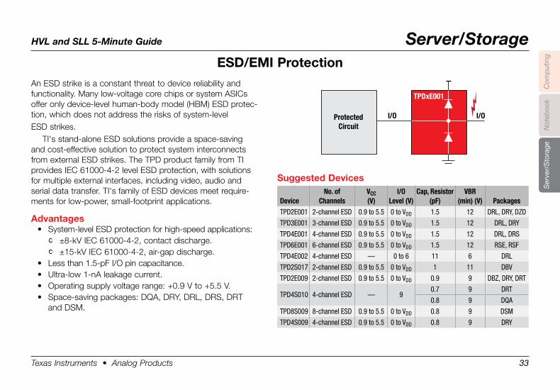
ESD/EMI .Protection
Protected
Circuit
I/O I/O
TPDxE001
An ESD strike is a constant threat to device reliability and functionality. Many low-voltage core chips or system ASICs offer only device-level human-body model (HBM) ESD protec-tion, which does not address the risks of system-levelESD strikes.
TI's stand-alone ESD solutions provide a space-saving and cost-effective solution to protect system interconnects from external ESD strikes. The TPD product family from TI provides IEC 61000-4-2 level ESD protection, with solutions for multiple external interfaces, including video, audio and serial data transfer. TI's family of ESD devices meet require-ments for low-power, small-footprint applications.
Advantages• System-level ESD protection for high-speed applications:
• ±8-kV IEC 61000-4-2, contact discharge.• ±15-kV IEC 61000-4-2, air-gap discharge.
• Less than 1.5-pF I/O pin capacitance.• Ultra-low 1-nA leakage current.• Operating supply voltage range: +0.9 V to +5.5 V.• Space-saving packages: DQA, DRY, DRL, DRS, DRT
and DSM.
Suggested .Devices
DeviceNo. of
ChannelsVCC(V)
I/OLevel (V)
Cap, Resistor(pF)
VBR(min) (V) Packages
TPD2E001 2-channel ESD 0.9 to 5.5 0 to VDD 1.5 12 DRL, DRY, DZD
TPD3E001 3-channel ESD 0.9 to 5.5 0 to VDD 1.5 12 DRL, DRY
TPD4E001 4-channel ESD 0.9 to 5.5 0 to VDD 1.5 12 DRL, DRS
TPD6E001 6-channel ESD 0.9 to 5.5 0 to VDD 1.5 12 RSE, RSF
TPD4E002 4-channel ESD — 0 to 6 11 6 DRL
TPD2S017 2-channel ESD 0.9 to 5.5 0 to VDD 1 11 DBV
TPD2E009 2-channel ESD 0.9 to 5.5 0 to VDD 0.9 9 DBZ, DRY, DRT
0.7 9 DRTTPD4S010 4-channel ESD — 9
0.8 9 DQA
TPD8S009 8-channel ESD 0.9 to 5.5 0 to VDD 0.8 9 DSM
TPD4S009 4-channel ESD 0.9 to 5.5 0 to VDD 0.8 9 DRY
HVL and SLL 5-Minute Guide Server/Storage
Texas Instruments • Analog Products 34
Com
put
ing
Not
eboo
kS
erve
r/S
tora
ge
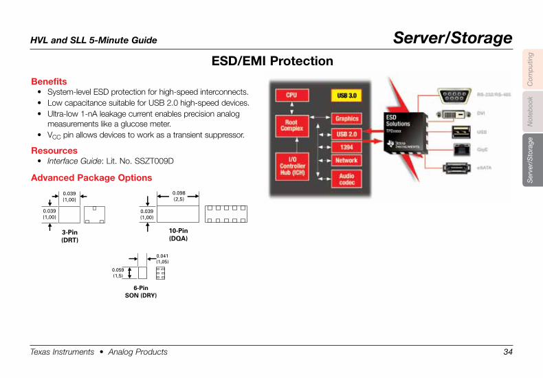
ESD/EMI .Protection
Benefits• System-level ESD protection for high-speed interconnects.• Low capacitance suitable for USB 2.0 high-speed devices.• Ultra-low 1-nA leakage current enables precision analog
measurements like a glucose meter.• VCC pin allows devices to work as a transient suppressor.
Resources• Interface Guide: Lit. No. SSZT009D
Advanced .Package .Options
0.041(1,05)
0.059(1,5)
6-Pin SON (DRY)
0.039(1,00)
0.039(1,00)
3-Pin (DRT)
0.098(2,5)
0.039(1,00)
10-Pin (DQA)
HVL and SLL 5-Minute Guide Consumer Medical
Texas Instruments • Analog Products 35
Com
put
ing
Not
eboo
kC
onsu
mer
Med
ical
Ser
ver/
Sto
rage
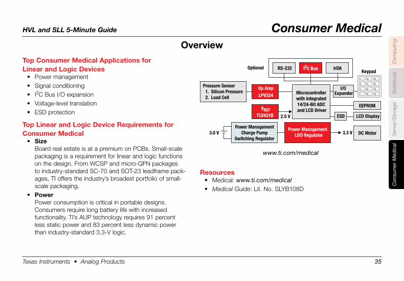
Top .Consumer .Medical .Applications .for . .Linear .and .Logic .Devices
• Power management• Signal conditioning• I2C Bus I/O expansion• Voltage-level translation• ESD protection
Top .Linear .and .Logic .Device .Requirements .for . .Consumer .Medical
• SizeBoard real estate is at a premium on PCBs. Small-scale packaging is a requirement for linear and logic functions on the design. From WCSP and micro-QFN packages to industry-standard SC-70 and SOT-23 leadframe pack-ages, TI offers the industry’s broadest portfolio of small-scale packaging.
• PowerPower consumption is critical in portable designs. Consumers require long battery life with increased functionality. TI’s AUP tech nology requires 91 percent less static power and 83 percent less dynamic power than industry-standard 3.3-V logic.
Overview
www.ti.com/medical
Resources• Medical: www.ti.com/medical• Medical Guide: Lit. No. SLYB108D
Op Amp
LCD DisplayESD
I/O ExpanderLPV324
3.3 V3.0 V
Keypad
DC MotorPower Management
Charge PumpSwitching Regulator
Pressure Sensor1. Silicon Pressure2. Load Cell
Power ManagementLDO Regulator
VREFTLV431B 2.5 V
Microcontrollerwith Integrated14/24-Bit ADCand LCD Driver
EEPROM
RS-232 I C Bus2Optional IrDA
HVL and SLL 5-Minute Guide Consumer Medical
Texas Instruments • Analog Products 36
Com
put
ing
Not
eboo
kC
onsu
mer
Med
ical
Ser
ver/
Sto
rage
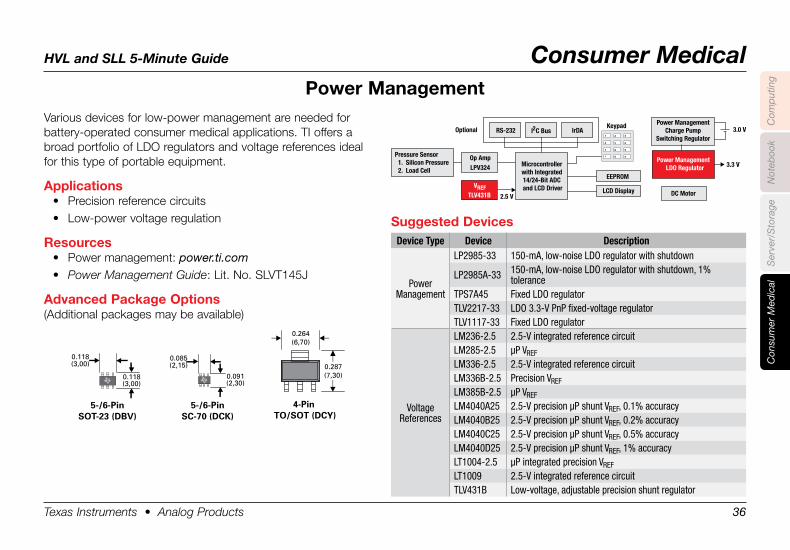
Various devices for low-power management are needed for battery-operated consumer medical applications. TI offers a broad portfolio of LDO regulators and voltage references ideal for this type of portable equipment.
Applications• Precision reference circuits• Low-power voltage regulation
Resources• Power management: power.ti.com• Power Management Guide: Lit. No. SLVT145J
Advanced .Package .Options(Additional packages may be available)
Power .Management
Op Amp
LCD Display
LPV324 3.3 V
3.0 VKeypad
DC Motor
Power ManagementCharge Pump
Switching Regulator
Pressure Sensor1. Silicon Pressure2. Load Cell
Power ManagementLDO Regulator
VREFTLV431B 2.5 V
Microcontrollerwith Integrated14/24-Bit ADCand LCD Driver
EEPROM
RS-232 I C Bus2Optional IrDA
Suggested .DevicesDevice Type Device Description
Power Management
LP2985-33 150-mA, low-noise LDO regulator with shutdown
LP2985A-33 150-mA, low-noise LDO regulator with shutdown, 1% tolerance
TPS7A45 Fixed LDO regulatorTLV2217-33 LDO 3.3-V PnP fixed-voltage regulatorTLV1117-33 Fixed LDO regulator
Voltage References
LM236-2.5 2.5-V integrated reference circuitLM285-2.5 µP VREF
LM336-2.5 2.5-V integrated reference circuitLM336B-2.5 Precision VREF
LM385B-2.5 µP VREF
LM4040A25 2.5-V precision µP shunt VREF, 0.1% accuracyLM4040B25 2.5-V precision µP shunt VREF, 0.2% accuracyLM4040C25 2.5-V precision µP shunt VREF, 0.5% accuracyLM4040D25 2.5-V precision µP shunt VREF, 1% accuracyLT1004-2.5 µP integrated precision VREF
LT1009 2.5-V integrated reference circuitTLV431B Low-voltage, adjustable precision shunt regulator
0.118(3,00)
0.118(3,00)
5-/6-PinSOT-23 (DBV)
0.085(2,15)
0.091(2,30)
5-/6-PinSC-70 (DCK)
0.264(6,70)
0.287(7,30)
4-Pin TO/SOT (DCY)
HVL and SLL 5-Minute Guide Consumer Medical
Texas Instruments • Analog Products 37
Com
put
ing
Not
eboo
kC
onsu
mer
Med
ical
Ser
ver/
Sto
rage
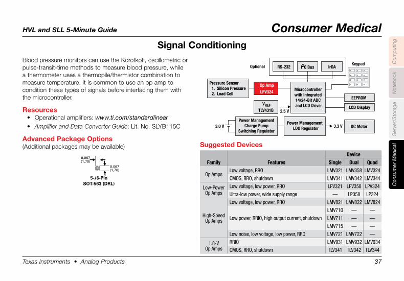
Blood pressure monitors can use the Korotkoff, oscillometric or pulse-transit-time methods to measure blood pressure, while a thermometer uses a thermopile/thermistor combination to measure temperature. It is common to use an op amp to condition these types of signals before interfacing them with the microcontroller.
Resources• Operational amplifiers: www.ti.com/standardlinear• Amplifier and Data Converter Guide: Lit. No. SLYB115C
Advanced .Package .Options(Additional packages may be available)
Signal .Conditioning
Op Amp
LCD Display
LPV324
3.3 V3.0 V
Keypad
DC MotorPower Management
Charge PumpSwitching Regulator
Pressure Sensor1. Silicon Pressure2. Load Cell
Power ManagementLDO Regulator
VREFTLV431B 2.5 V
Microcontrollerwith Integrated14/24-Bit ADCand LCD Driver
EEPROM
RS-232 I C Bus2Optional IrDA
Suggested .Devices
Family FeaturesDevice
Single Dual Quad
Op AmpsLow voltage, RRO LMV321 LMV358 LMV324
CMOS, RRO, shutdown LMV341 LMV342 LMV344
Low-PowerOp Amps
Low voltage, low power, RRO LPV321 LPV358 LPV324
Ultra-low power, wide supply range — LP358 LP324
High-SpeedOp Amps
Low voltage, low power, RRO LMV821 LMV822 LMV824
Low power, RRIO, high output current, shutdown
LMV710 — —
LMV711 — —
LMV715 — —
Low noise, low voltage, low power, RRO LMV721 LMV722 —
1.8-VOp Amps
RRIO LMV931 LMV932 LMV934
CMOS, RRO, shutdown TLV341 TLV342 TLV344
0.067(1,70)
0.067(1,70)
5-/6-PinSOT-563 (DRL)
HVL and SLL 5-Minute Guide Consumer Medical
Texas Instruments • Analog Products 38
Com
put
ing
Not
eboo
kC
onsu
mer
Med
ical
Ser
ver/
Sto
rage
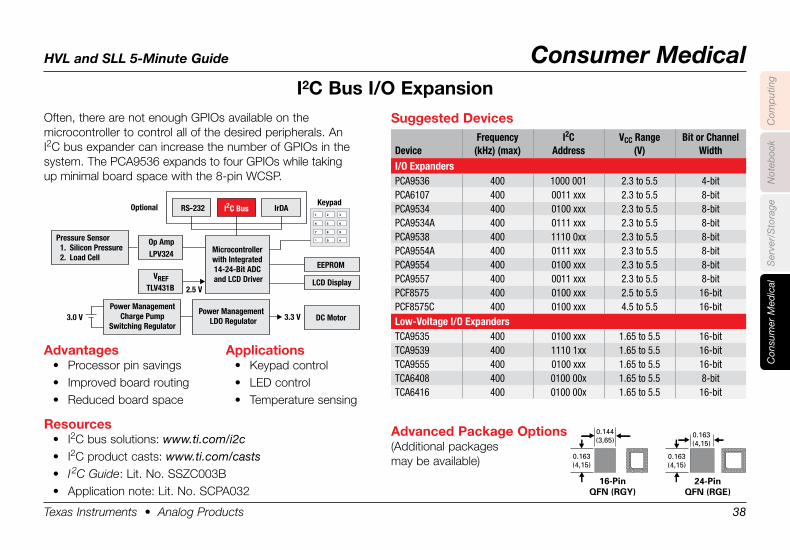
Often, there are not enough GPIOs available on the microcontroller to control all of the desired peripherals. An I2C bus expander can increase the number of GPIOs in the system. The PCA9536 expands to four GPIOs while taking up minimal board space with the 8-pin WCSP.
I2C .Bus .I/O .Expansion
0.144(3,65)
0.163(4,15)
16-PinQFN (RGY)
0.163(4,15)
0.163(4,15)
24-PinQFN (RGE)
Applications• Keypad control• LED control• Temperature sensing
Advanced .Package .Options(Additional packages may be available)
Advantages• Processor pin savings• Improved board routing• Reduced board space
Resources• I2C bus solutions: www.ti.com/i2c• I2C product casts: www.ti.com/casts• I 2C Guide: Lit. No. SSZC003B• Application note: Lit. No. SCPA032
Op Amp
LCD Display
LPV324
3.3 V3.0 V
Keypad
DC MotorPower Management
Charge PumpSwitching Regulator
Pressure Sensor1. Silicon Pressure2. Load Cell
Power ManagementLDO Regulator
VREFTLV431B 2.5 V
Microcontrollerwith Integrated14-24-Bit ADCand LCD Driver
EEPROM
RS-232 I C Bus2Optional IrDA
Suggested .Devices
DeviceFrequency
(kHz) (max)I2C
AddressVCC Range
(V)Bit or Channel
WidthI/O ExpandersPCA9536 400 1000 001 2.3 to 5.5 4-bitPCA6107 400 0011 xxx 2.3 to 5.5 8-bitPCA9534 400 0100 xxx 2.3 to 5.5 8-bitPCA9534A 400 0111 xxx 2.3 to 5.5 8-bitPCA9538 400 1110 0xx 2.3 to 5.5 8-bitPCA9554A 400 0111 xxx 2.3 to 5.5 8-bitPCA9554 400 0100 xxx 2.3 to 5.5 8-bitPCA9557 400 0011 xxx 2.3 to 5.5 8-bitPCF8575 400 0100 xxx 2.5 to 5.5 16-bitPCF8575C 400 0100 xxx 4.5 to 5.5 16-bitLow-Voltage I/O ExpandersTCA9535 400 0100 xxx 1.65 to 5.5 16-bitTCA9539 400 1110 1xx 1.65 to 5.5 16-bitTCA9555 400 0100 xxx 1.65 to 5.5 16-bitTCA6408 400 0100 00x 1.65 to 5.5 8-bitTCA6416 400 0100 00x 1.65 to 5.5 16-bit
HVL and SLL 5-Minute Guide Consumer Medical
Texas Instruments • Analog Products 39
Com
put
ing
Not
eboo
kC
onsu
mer
Med
ical
Ser
ver/
Sto
rage
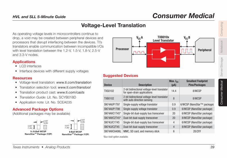
As operating voltage levels in microcontrollers continue to drop, a void may be created between peripheral devices and processors that disrupt interfacing between the devices. TI’s translators enable communication between incompatible I/Os withleveltranslationbetweenthe1.2-V,1.5-V,1.8-V,2.5-Vand 3.3-V nodes.
Applications• LCDinterfaces• Interfacedeviceswithdifferentsupplyvoltages
Resources• Voltage-leveltranslation:www.ti.com/translation• Translationselectiontool:www.ti.com/transtool• Translationproductcast:www.ti.com/casts• Translation Guide:Lit.No.SCYB018D• Applicationnote:Lit.No.SCEA035
Advanced Package Options(Additional packages may be available)
Voltage-Level Translation
V ACC
V BCC
TXB010x
Level Translator
PeripheralProcessor
0.037(0,95)
0.057(1,45)
5-/6-Ball WCSPNanoStarTM Package (YZP)
0.037(0,95)
0.077(1,95)
8-Ball WCSPNanoStarTM Package (YZP)
Suggested Devices
Device DescriptionMax. ICC
(µA)Smallest Footprint
Pins/Packages
TXS0102 2-bit bidirectional voltage-level translator for open-drain applications 14.4 8/WCSP
TXB0102 2-bit bidirectional voltage-level translator with auto direction sensing 8 8/WCSP
SN74AUP1T97 Single-supply voltage translator 0.9 6/WCSP (NanoStar™ package)
SN74AUP1T98 Single-supply voltage translator 0.9 6/WCSP (NanoStar package)
SN74AVC1T45* Single-bit dual-supply bus transceiver 20 6/WCSP (NanoStar package)
SN74AVC2T45* Dual-bit dual-supply transceiver 20 8/WCSP (NanoStar package)
SN74LVC1T45 Single-bit dual-supply bus transceiver 4 6/WCSP (NanoStar package)
SN74LVC2T45 Dual-bit dual-supply transceiver 4 8/WCSP (NanoStar package)
SN74AVCA406L MMC, SD card, and memory stick 6 20/ZXY
*Bus-hold option available.
HVL and SLL 5-Minute Guide Consumer Medical
Texas Instruments • Analog Products 40
Com
put
ing
Not
eboo
kC
onsu
mer
Med
ical
Ser
ver/
Sto
rage
ESD .Protection
Protected
Circuit
I/O I/O
TPDxE001
0.067(1,70)
0.067(1,70)
5-/6-PinSOT-563 (DRL)
0.041(1,05)
0.059(1,5)
6-Pin SON (DRY)
Advanced .Package .Options
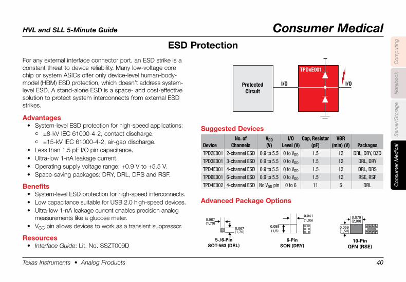
For any external interface connector port, an ESD strike is a constant threat to device reliability. Many low-voltage core chip or system ASICs offer only device-level human-body-model (HBM) ESD protection, which doesn’t address system-level ESD. A stand-alone ESD is a space- and cost-effective solution to protect system interconnects from external ESD strikes.
Advantages• System-level ESD protection for high-speed applications:
• ±8-kV IEC 61000-4-2, contact discharge.• ±15-kV IEC 61000-4-2, air-gap discharge.
• Less than 1.5 pF I/O pin capacitance.• Ultra-low 1-nA leakage current.• Operating supply voltage range: +0.9 V to +5.5 V.• Space-saving packages: DRY, DRL, DRS and RSF.
Benefits• System-level ESD protection for high-speed interconnects.• Low capacitance suitable for USB 2.0 high-speed devices.• Ultra-low 1-nA leakage current enables precision analog
measurements like a glucose meter.• VCC pin allows devices to work as a transient suppressor.
Resources• Interface Guide: Lit. No. SSZT009D
Suggested .Devices
DeviceNo. of
ChannelsVDD(V)
I/OLevel (V)
Cap, Resistor(pF)
VBR(min) (V) Packages
TPD2E001 2-channel ESD 0.9 to 5.5 0 to VDD 1.5 12 DRL, DRY, DZD
TPD3E001 3-channel ESD 0.9 to 5.5 0 to VDD 1.5 12 DRL, DRY
TPD4E001 4-channel ESD 0.9 to 5.5 0 to VDD 1.5 12 DRL, DRS
TPD6E001 6-channel ESD 0.9 to 5.5 0 to VDD 1.5 12 RSE, RSF
TPD4E002 4-channel ESD No VDD pin 0 to 6 11 6 DRL
0.079(2,00)
0.059 (1,50)
10-PinQFN (RSE)
HVL and SLL 5-Minute Guide Handsets
Texas Instruments • Analog Products 41
Han
dse
tsC
omp
utin
gN
oteb
ook
Con
sum
er M
edic
alS
erve
r/S
tora
ge
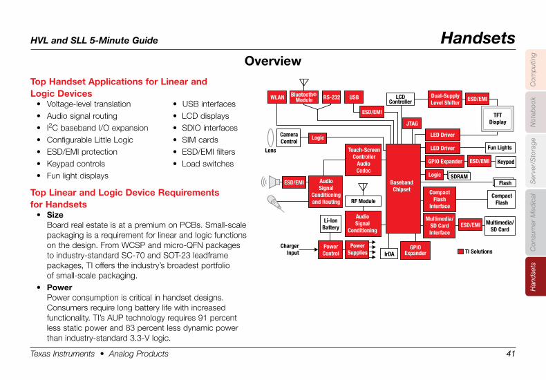
Top .Handset .Applications .for .Linear .and .Logic .Devices
• Voltage-level translation • USB interfaces• Audio signal routing • LCD displays• I2C baseband I/O expansion • SDIO interfaces• Configurable Little Logic • SIM cards• ESD/EMI protection • ESD/EMI filters• Keypad controls • Load switches• Fun light displays
Top .Linear .and .Logic .Device .Requirements . .for .Handsets
• SizeBoard real estate is at a premium on PCBs. Small-scale packaging is a requirement for linear and logic functions on the design. From WCSP and micro-QFN packages to industry-standard SC-70 and SOT-23 leadframe packages, TI offers the industry’s broadest portfolio of small-scale packaging.
• PowerPower consumption is critical in handset designs. Consumers require long battery life with increased functionality. TI’s AUP tech nology requires 91 percent less static power and 83 percent less dynamic power than industry-standard 3.3-V logic.
Overview
AudioSignal
Conditioning
Touch-ScreenController
AudioCodec
AudioSignal
Conditioningand Routing
CameraControl
Lens
Logic
WLAN RS-232 USB
JTAG
Fun Lights
Keypad
Bluetooth®Module
Dual-SupplyLevel Shifter
CompactFlash
Interface
CompactFlash
Multimedia/SD CardInterface
Multimedia/SD Card
LCDController
IrDA TI Solutions
RF Module
GPIOExpander
PowerSupplies
PowerControl
Li-IonBattery
ChargerInput
Flash
TFTDisplay
LED Driver
LED Driver
GPIO Expander
SDRAMLogicBasebandChipset
ESD/EMI
ESD/EMI
ESD/EMI
ESD/EMI
ESD/EMI
HVL and SLL 5-Minute Guide Handsets
Texas Instruments • Analog Products 42
Han
dse
tsC
omp
utin
gN
oteb
ook
Con
sum
er M
edic
alS
erve
r/S
tora
ge
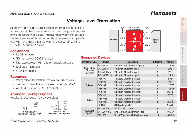
Voltage-Level TranslationAs operating voltage levels in baseband processors continue to drop, a void has been created between peripheral devices and processors that disrupt interfacing between the devices. TI’s translators enable communication between incompatible I/Oswithleveltranslationbetweenthe1.2-V,1.5-V,1.8-V, 2.5-V, 3.3-V and 5-V nodes.
Applications• LCDinterfaces• SDmemoryorSDIOinterface• Interfacedeviceswithdifferentsupplyvoltages• SIMcardinterfaces• WLANinterfaces
Resources• Voltage-leveltranslation:www.ti.com/translation• Translationselectiontool:www.ti.com/transtool• Applicationnote:Lit.No.SCEA035
Advanced Package Options(Additional packages may be available)
Suggested DevicesTranslator Type Device Description Bit Width Package
Dual-Supply Direction Controlled
SN74AVC4T774 4-bit with four DIR control signals 4 16/RSVSN74AVC1T45 1-bit with DIR control signal 1 6/YZPSN74AVC2T45 2-bit with DIR control signal 2 8/YZPSN74AVC8T245 8-bit with DIR control signal 8 24/RHL
Buffered
TXB0101 1-bit auto-direction translator 1 6/YZPTXB0102 2-bit auto-direction translator 2 8/YZPTXB0104 4-bit auto-direction translator 4 12/YZTTXB0106 6-bit auto-direction translator 6 16/RGYTXB0108 8-bit auto-direction translator 8 20/DQS
Switch
TXS0102 2-bit auto-direction translator 2 8/YZPTXS0104E 4-bit auto-direction translator 4 14/YZTTXS0108E 8-bit auto-direction translator 8 20/DQSTXS02612 SDIO port expander - 24/ZQS
ApplicationSpecific
SN74AVC6T622 AC ’97 (audio codec) 6 20/ZXYSN74AVCA406L MMC, SD Card, and Memory Stick 6 20/ZXYTWL1200 WiLink™ (WLAN+BT+FM) transceiver 19 49/WCSP
V ACC
V BCC
SN74AVCA406L
Level Translator
SD/SDIO
Card
Processor
DATA_A
4 4
CMD_A
CLK_A
DATA_B
CMD_B
CLK_B
0.037(0,95)
0.057(1,45)
5-/6-Ball WCSPNanoStarTM Package (YZP)
0.037(0,95)
0.077(1,95)
8-Ball WCSPNanoStarTM Package (YZP)
HVL and SLL 5-Minute Guide Handsets
Texas Instruments • Analog Products 43
Han
dse
tsC
omp
utin
gN
oteb
ook
Con
sum
er M
edic
alS
erve
r/S
tora
ge
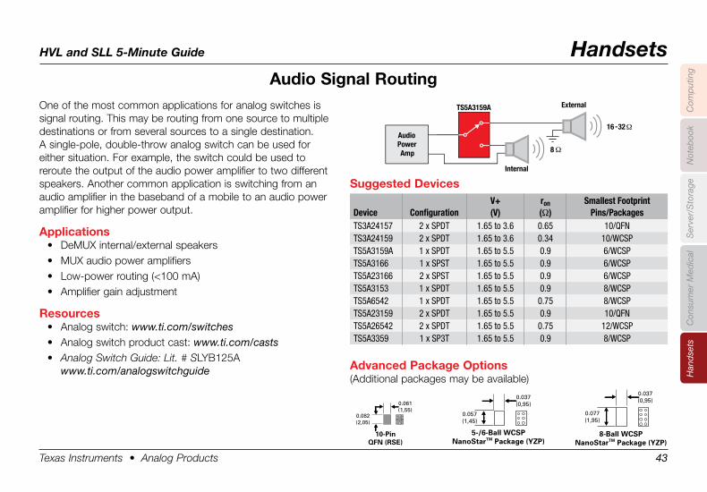
Audio .Signal .RoutingOne of the most common applications for analog switches is signal routing. This may be routing from one source to multiple destinations or from several sources to a single destination. A single-pole, double-throw analog switch can be used for either situation. For example, the switch could be used to reroute the output of the audio power amplifier to two different speakers. Another common application is switching from an audio amplifier in the baseband of a mobile to an audio power amplifier for higher power output.
Applications• DeMUX internal/external speakers• MUX audio power amplifiers• Low-power routing (<100 mA)• Amplifier gain adjustment
Resources• Analog switch: www.ti.com/switches• Analog switch product cast: www.ti.com/casts• Analog Switch Guide: Lit. # SLYB125A
www.ti.com/analogswitchguide
Suggested .Devices
Device ConfigurationV+(V)
ron(Ω)
Smallest FootprintPins/Packages
TS3A24157 2 x SPDT 1.65 to 3.6 0.65 10/QFNTS3A24159 2 x SPDT 1.65 to 3.6 0.34 10/WCSPTS5A3159A 1 x SPDT 1.65 to 5.5 0.9 6/WCSPTS5A3166 1 x SPST 1.65 to 5.5 0.9 6/WCSPTS5A23166 2 x SPST 1.65 to 5.5 0.9 6/WCSPTS5A3153 1 x SPDT 1.65 to 5.5 0.9 8/WCSPTS5A6542 1 x SPDT 1.65 to 5.5 0.75 8/WCSPTS5A23159 2 x SPDT 1.65 to 5.5 0.9 10/QFNTS5A26542 2 x SPDT 1.65 to 5.5 0.75 12/WCSPTS5A3359 1 x SP3T 1.65 to 5.5 0.9 8/WCSP
External
Internal
16 -32Ω
8 Ω
TS5A3159A
Audio Power Am p
0.037(0,95)
0.057(1,45)
5-/6-Ball WCSPNanoStarTM Package (YZP)
0.037(0,95)
0.077(1,95)
8-Ball WCSPNanoStarTM Package (YZP)
0.061(1,55)
0.082(2,05)
10-PinQFN (RSE)
Advanced .Package .Options(Additional packages may be available)
HVL and SLL 5-Minute Guide Handsets
Texas Instruments • Analog Products 44
Han
dse
tsC
omp
utin
gN
oteb
ook
Con
sum
er M
edic
alS
erve
r/S
tora
ge
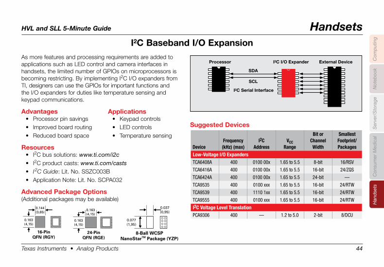
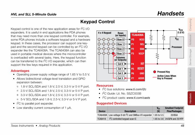
I2C .Baseband .I/O .ExpansionAs more features and processing requirements are added to applications such as LED control and camera interfaces in handsets, the limited number of GPIOs on microprocessors is becoming restricting. By implementing I2C I/O expanders from TI, designers can use the GPIOs for important functions and the I/O expanders for duties like temperature sensing and keypad communications.
Advantages• Processor pin savings• Improved board routing• Reduced board space
Resources• I2C bus solutions: www.ti.com/i2c• I2C product casts: www.ti.com/casts• I 2C Guide: Lit. No. SSZC003B• Application Note: Lit. No. SCPA032
Advanced .Package .Options(Additional packages may be available)
Suggested .Devices
DeviceFrequency
(kHz) (max)I2C
AddressVCC
Range
Bit or Channel Width
Smallest Footprint/Packages
Low-Voltage I/O ExpandersTCA6408A 400 0100 00x 1.65 to 5.5 8-bit 16/RSV
TCA6416A 400 0100 00x 1.65 to 5.5 16-bit 24/ZQS
TCA6424A 400 0100 00x 1.65 to 5.5 24-bit —
TCA9535 400 0100 xxx 1.65 to 5.5 16-bit 24/RTW
TCA9539 400 1110 1xx 1.65 to 5.5 16-bit 24/RTW
TCA9555 400 0100 xxx 1.65 to 5.5 16-bit 24/RTW
I2C Voltage Level TranslationPCA9306 400 — 1.2 to 5.0 2-bit 8/DCU
0.037(0,95)
0.077(1,95)
8-Ball WCSPNanoStarTM Package (YZP)
0.144(3,65)
0.163(4,15)
16-PinQFN (RGY)
0.163(4,15)
0.163(4,15)
24-PinQFN (RGE)
Applications• Keypad controls• LED controls• Temperature sensing
Processor
SDA
SCL
I2C I/O Expander
I2C Serial Interface
External Device
HVL and SLL 5-Minute Guide Handsets
Texas Instruments • Analog Products 45
Han
dse
tsC
omp
utin
gN
oteb
ook
Con
sum
er M
edic
alS
erve
r/S
tora
ge
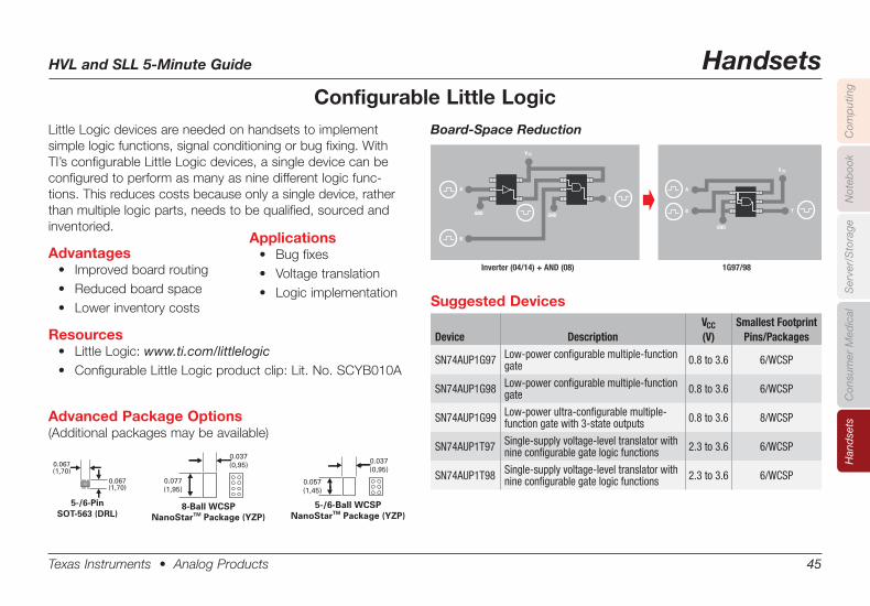
Configurable Little LogicLittle Logic devices are needed on handsets to implement simple logic functions, signal conditioning or bug fixing. With TI’s configurable Little Logic devices, a single device can be configured to perform as many as nine different logic func-tions. This reduces costs because only a single device, rather than multiple logic parts, needs to be qualified, sourced and inventoried.
Advantages• Improvedboardrouting• Reducedboardspace• Lowerinventorycosts
Resources• LittleLogic:www.ti.com/littlelogic• ConfigurableLittleLogicproductclip:Lit.No.SCYB010A
Advanced Package Options(Additional packages may be available)
Suggested Devices
Device DescriptionVCC(V)
Smallest FootprintPins/Packages
SN74AUP1G97 Low-power configurable multiple-function gate 0.8 to 3.6 6/WCSP
SN74AUP1G98 Low-power configurable multiple-function gate 0.8 to 3.6 6/WCSP
SN74AUP1G99 Low-power ultra-configurable multiple-function gate with 3-state outputs 0.8 to 3.6 8/WCSP
SN74AUP1T97 Single-supply voltage-level translator with nine configurable gate logic functions 2.3 to 3.6 6/WCSP
SN74AUP1T98 Single-supply voltage-level translator with nine configurable gate logic functions 2.3 to 3.6 6/WCSP
GND
Inverter (04/14) + AND (08) 1G97/98
V CC
GND
Y
A
B
GND
V CC
A
B Y
Board-Space Reduction
0.037(0,95)
0.057(1,45)
5-/6-Ball WCSPNanoStarTM Package (YZP)
0.037(0,95)
0.077(1,95)
8-Ball WCSPNanoStarTM Package (YZP)
Applications• Bugfixes• Voltagetranslation• Logicimplementation
Board-Space Reduction
0.067(1,70)
0.067(1,70)
5-/6-PinSOT-563 (DRL)
HVL and SLL 5-Minute Guide Handsets
Texas Instruments • Analog Products 46
Han
dse
tsC
omp
utin
gN
oteb
ook
Con
sum
er M
edic
alS
erve
r/S
tora
ge
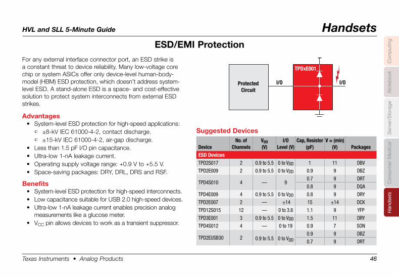
ESD/EMI .Protection
Protected
Circuit
I/O I/O
TPDxE001
For any external interface connector port, an ESD strike is a constant threat to device reliability. Many low-voltage core chip or system ASICs offer only device-level human-body-model (HBM) ESD protection, which doesn’t address system-level ESD. A stand-alone ESD is a space- and cost-effective solution to protect system interconnects from external ESD strikes.
Advantages• System-level ESD protection for high-speed applications:
• ±8-kV IEC 61000-4-2, contact discharge.• ±15-kV IEC 61000-4-2, air-gap discharge.
• Less than 1.5 pF I/O pin capacitance.• Ultra-low 1-nA leakage current.• Operating supply voltage range: +0.9 V to +5.5 V.• Space-saving packages: DRY, DRL, DRS and RSF.
Benefits• System-level ESD protection for high-speed interconnects.• Low capacitance suitable for USB 2.0 high-speed devices.• Ultra-low 1-nA leakage current enables precision analog
measurements like a glucose meter.• VCC pin allows devices to work as a transient suppressor.
Suggested .Devices
DeviceNo. of
ChannelsVDD(V)
I/OLevel (V)
Cap, Resistor(pF)
V = (min) (V) Packages
ESD DevicesTPD2S017 2 0.9 to 5.5 0 to VDD 1 11 DBV
TPD2E009 2 0.9 to 5.5 0 to VDD 0.9 9 DBZ
0.7 9 DRTTPD4S010 4 — 9
0.8 9 DQA
TPD4E009 4 0.9 to 5.5 0 to VDD 0.8 9 DRY
TPD2E007 2 — ±14 15 ±14 DCK
TPD12S015 12 — 0 to 3.6 1.1 9 YFP
TPD3E001 3 0.9 to 5.5 0 to VDD 1.5 11 DRY
TPD4S012 4 — 0 to 19 0.9 7 SON
TPD2EUSB30 2 0.9 to 5.5 0 to VDD0.9 9 DBZ
0.7 9 DRT
HVL and SLL 5-Minute Guide Handsets
Texas Instruments • Analog Products 47
Han
dse
tsC
omp
utin
gN
oteb
ook
Con
sum
er M
edic
alS
erve
r/S
tora
ge
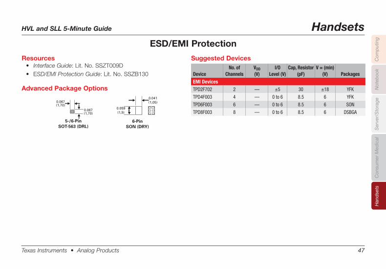
Suggested Devices
DeviceNo. of
ChannelsVDD(V)
I/OLevel (V)
Cap, Resistor(pF)
V = (min) (V) Packages
EMI DevicesTPD2F702 2 — ±5 30 ±18 YFK
TPD4F003 4 — 0 to 6 8.5 6 YFK
TPD6F003 6 — 0 to 6 8.5 6 SON
TPD8F003 8 — 0 to 6 8.5 6 DSBGA
ESD/EMI Protection
Resources• Interface Guide: Lit. No. SSZT009D• ESD/EMI Protection Guide:Lit.No.SSZB130
0.067(1,70)
0.067(1,70)
5-/6-PinSOT-563 (DRL)
0.041(1,05)
0.059(1,5)
6-Pin SON (DRY)
Advanced Package Options
HVL and SLL 5-Minute Guide Handsets
Texas Instruments • Analog Products 48
Han
dse
tsC
omp
utin
gN
oteb
ook
Con
sum
er M
edic
alS
erve
r/S
tora
ge
Keypad .ControlKeypad control is one of the new application areas for I2C I/O expanders. It is useful in end applications like PDA phones that may need more than one keypad controller. For example, some PDA phones include a software keypad and a hardware keypad. In these cases, the processor can support one key-pad and the second keypad can be controlled by an I2C I/O expander like the TCA6408A. The TCA6408A can also be used in portable medical devices where the microcontroller is overloaded with several tasks. Here, the keypad function can be transferred to the I2C I/O expander, which can then support the few keys required in this application.
Advantages• Operating power-supply voltage range of 1.65 V to 5.5 V.• Allows bidirectional voltage-level translation and GPIO
expansion between:• 1.8-V SCL/SDA and 1.8-V, 2.5-V, 3.3-V or 5-V P port.• 2.5-V SCL/SDA and 1.8-V, 2.5-V, 3.3-V or 5-V P port.• 3.3-V SCL/SDA and 1.8-V, 2.5-V, 3.3-V or 5-V P port.• 5-V SCL/SDA and 1.8-V, 2.5-V, 3.3-V or 5-V P port.
• I2C to parallel port expander.• Low standby current consumption of 1 µA.
Rows(or Inputs)
Columns(or Outputs)
4 x 4 Keypad
Pressed Key
Active Lines WhenKey is Pressed
VCCI(1.8 V)
Row 0
Row 2
Row 1
Row 3
Col 0
Col 2
Col 1
Col 3
PO
P1
P2
P3
P4
P5
P6
P7 ADDR
SCL
SDA
VCCI
INT
RESET
VCCP
GND
TCA6408A
Processor
VCC
Resources• I2C bus solutions: www.ti.com/i2c• I2C Guide: Lit. No. SSZC003B• I2C product casts: www.ti.com/casts
Suggested .Devices
Device DescriptionVCC(V)
Smallest FootprintPins/Packages
TCA6408A Low-voltage 8-bit I2C and SMBus I/O expander 1.65 to 5.5 20/BGA
TCA8418 I2C controlled keypad scan IC 1.65 to 3.6 24/QFN and 25/YFP
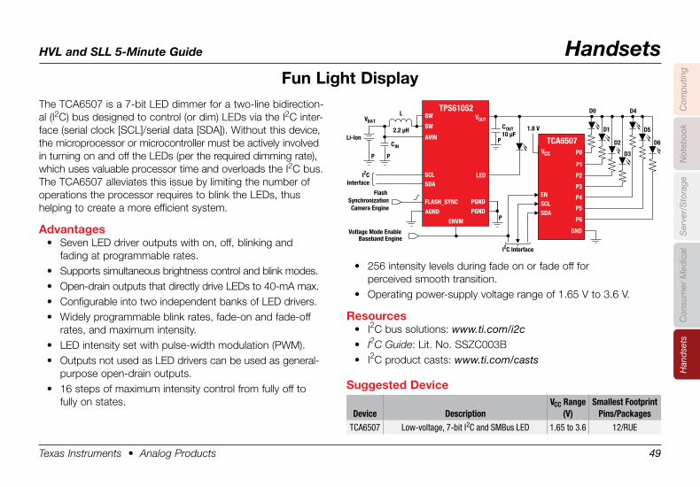
HVL and SLL 5-Minute Guide Handsets
Texas Instruments • Analog Products 49
Han
dse
tsC
omp
utin
gN
oteb
ook
Con
sum
er M
edic
alS
erve
r/S
tora
ge
Fun .Light .DisplayThe TCA6507 is a 7-bit LED dimmer for a two-line bidirection-al (I2C) bus designed to control (or dim) LEDs via the I2C inter-face (serial clock [SCL]/serial data [SDA]). Without this device, the microprocessor or microcontroller must be actively involved in turning on and off the LEDs (per the required dim ming rate), which uses valuable processor time and overloads the I2C bus. The TCA6507 alleviates this issue by limiting the number of operations the processor requires to blink the LEDs, thus helping to create a more efficient system.
Advantages• Seven LED driver outputs with on, off, blinking and
fading at programmable rates.• Supports simultaneous brightness control and blink modes.• Open-drain outputs that directly drive LEDs to 40-mA max.• Configurable into two independent banks of LED drivers.• Widely programmable blink rates, fade-on and fade-off
rates, and maximum intensity.• LED intensity set with pulse-width modulation (PWM).• Outputs not used as LED drivers can be used as general-
purpose open-drain outputs.• 16 steps of maximum intensity control from fully off to
fully on states.
• 256 intensity levels during fade on or fade off for perceived smooth transition.
• Operating power-supply voltage range of 1.65 V to 3.6 V.
Resources• I2C bus solutions: www.ti.com/i2c• I2C Guide: Lit. No. SSZC003B• I2C product casts: www.ti.com/casts
TCA6507
COUT
VBAT
CINP
P
PP
Li-Ion
L
Flash SynchronizationCamera Engine
Voltage Mode EnableBaseband Engine
10 µF2.2 µH
D0
D1
D2
I2CInterface
1.8 V
TPS61052VOUT
PGND
LED
ENVM
PGND
SW
SW
AVIN
AGND
SCLSDA
FLASH_SYNC
VCC
SCL
P0
P1
P6
P5
P4
P3
P2
SDA
EN
GND
I2C Interface
D3
D4
D5
D6
Suggested .Device
Device DescriptionVCC Range
(V)Smallest Footprint
Pins/PackagesTCA6507 Low-voltage, 7-bit I2C and SMBus LED 1.65 to 3.6 12/RUE
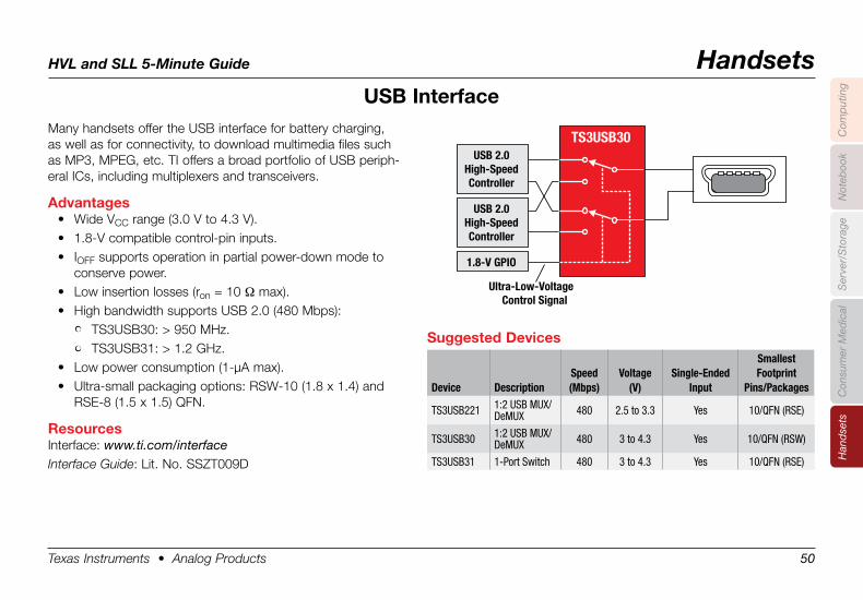
HVL and SLL 5-Minute Guide Handsets
Texas Instruments • Analog Products 50
Han
dse
tsC
omp
utin
gN
oteb
ook
Con
sum
er M
edic
alS
erve
r/S
tora
ge
USB .InterfaceMany handsets offer the USB interface for battery charging, as well as for connectivity, to download multimedia files such as MP3, MPEG, etc. TI offers a broad portfolio of USB periph-eral ICs, including multiplexers and transceivers.
Advantages• Wide VCC range (3.0 V to 4.3 V).• 1.8-V compatible control-pin inputs.• IOFF supports operation in partial power-down mode to
conserve power.• Low insertion losses (ron = 10 Ω max).• High bandwidth supports USB 2.0 (480 Mbps):
• TS3USB30: > 950 MHz.• TS3USB31: > 1.2 GHz.
• Low power consumption (1-µA max).• Ultra-small packaging options: RSW-10 (1.8 x 1.4) and
RSE-8 (1.5 x 1.5) QFN.
ResourcesInterface: www.ti.com/interfaceInterface Guide: Lit. No. SSZT009D
TS3USB30USB 2.0
High-SpeedController
USB 2.0High-SpeedController
1.8-V GPIO
Ultra-Low-VoltageControl Signal
Suggested .Devices
Device DescriptionSpeed(Mbps)
Voltage(V)
Single-EndedInput
Smallest Footprint
Pins/Packages
TS3USB221 1:2 USB MUX/DeMUX 480 2.5 to 3.3 Yes 10/QFN (RSE)
TS3USB30 1:2 USB MUX/DeMUX 480 3 to 4.3 Yes 10/QFN (RSW)
TS3USB31 1-Port Switch 480 3 to 4.3 Yes 10/QFN (RSE)
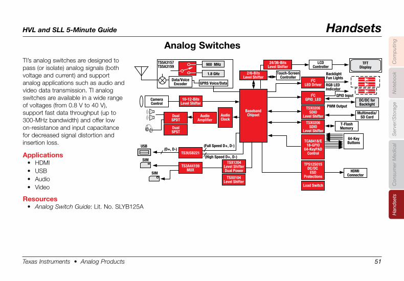
HVL and SLL 5-Minute Guide Handsets
Texas Instruments • Analog Products 51
Han
dse
tsC
omp
utin
gN
oteb
ook
Con
sum
er M
edic
alS
erve
r/S
tora
ge
Analog .SwitchesTI’s analog switches are designed to pass (or isolate) analog signals (both voltage and current) and support analog applications such as audio and video data transmission. TI analog switches are available in a wide range of voltages (from 0.8 V to 40 V), support fast data throughput (up to 300-MHz bandwidth) and offer low on-resistance and input capacitance for decreased signal distortion and insertion loss.
Applications• HDMI• USB• Audio• Video
Resources• Analog Switch Guide: Lit. No. SLYB125A
SIM
USB(D+, D-)
(Full Speed D+, D-)
(High Speed D+, D-)
TS5A3157TS5A3159
BasebandChipset
SIM
2/6-BitsLevel Shifter
24/36-BitsLevel Shifter
I2CLED Driver
TSX0104Level Shifter
TS3A44159MUX
TS3USB221
AudioAmplifier
DualSPDT
CameraControl
Data/VoiceEncoder GPRS Voice/Data
1.8 GHz
900 MHz
DualSPST
10-12-BitsLevel Shifter
TSX0206SDIO
Level Shifter
I2CGPIO_LED
Load Switch
TCA8418/E18-GPIO
64-KeyPADControl
AudioClock
TPS12S015DC/DC
ESDProtections
Touch-ScreenController
LCDController
T-FlashMemory
64-KeyButtons
Multimedia/SD Card
GPIO Input
PWM Output
BacklightFun Lights
RGB LEDIndicator
DC/DC forBacklight
TFTDisplay
HDMI Connector
TSX0206SDIO
Level Shifter
TSX1204Level ShifterDual Power
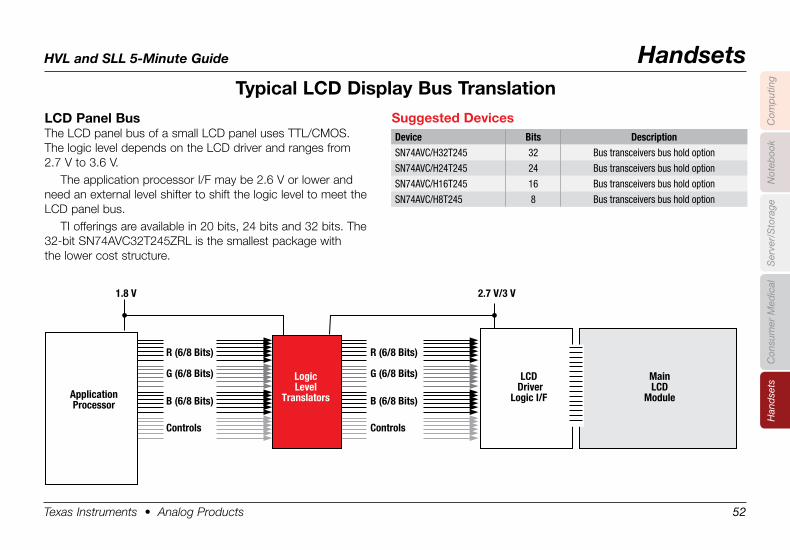
HVL and SLL 5-Minute Guide Handsets
Texas Instruments • Analog Products 52
Han
dse
tsC
omp
utin
gN
oteb
ook
Con
sum
er M
edic
alS
erve
r/S
tora
ge
Typical .LCD .Display .Bus .Translation
LCD .Panel .Bus .The LCD panel bus of a small LCD panel uses TTL/CMOS. The logic level depends on the LCD driver and ranges from 2.7 V to 3.6 V.
The application processor I/F may be 2.6 V or lower and need an external level shifter to shift the logic level to meet the LCD panel bus.
TI offerings are available in 20 bits, 24 bits and 32 bits. The 32-bit SN74AVC32T245ZRL is the smallest package with the lower cost structure.
1.8 V
R (6/8 Bits)
G (6/8 Bits)
B (6/8 Bits)
Controls
R (6/8 Bits)
G (6/8 Bits)
B (6/8 Bits)
Controls
2.7 V/3 V
LogicLevel
Translators
LCD Driver
Logic I/FApplicationProcessor
MainLCD
Module
Suggested .DevicesDevice Bits DescriptionSN74AVC/H32T245 32 Bus transceivers bus hold option
SN74AVC/H24T245 24 Bus transceivers bus hold option
SN74AVC/H16T245 16 Bus transceivers bus hold option
SN74AVC/H8T245 8 Bus transceivers bus hold option
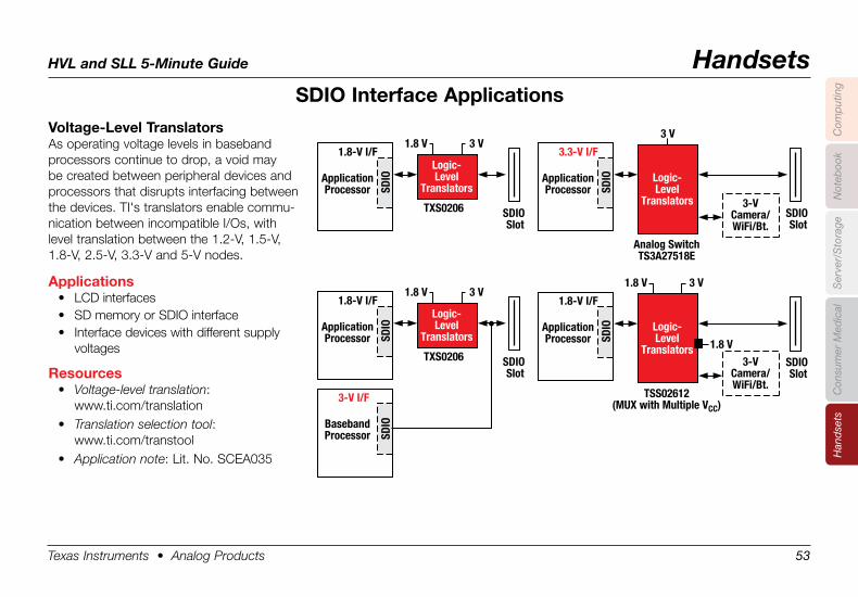
HVL and SLL 5-Minute Guide Handsets
Texas Instruments • Analog Products 53
Han
dse
tsC
omp
utin
gN
oteb
ook
Con
sum
er M
edic
alS
erve
r/S
tora
ge
SDIO .Interface .Applications
Voltage-Level .TranslatorsAs operating voltage levels in baseband processors continue to drop, a void may be created between peripheral devices and processors that disrupts interfacing between the devices. TI's translators enable commu-nication between incompatible I/Os, with level translation between the 1.2-V, 1.5-V, 1.8-V, 2.5-V, 3.3-V and 5-V nodes.
Applications• LCD interfaces• SD memory or SDIO interface• Interface devices with different supply
voltages
Resources• Voltage-level translation:
www.ti.com/translation• Translation selection tool:
www.ti.com/transtool• Application note: Lit. No. SCEA035
3 V1.8 V
1.8 V
1.8-V I/F
TXS0206 SDIO Slot
Logic-Level
TranslatorsApplicationProcessor
3 V1.8 V3 V1.8 V
SDIO
1.8-V I/F
TXS0206 SDIO Slot
Logic-Level
TranslatorsApplicationProcessor
3-V I/F
BasebandProcessor SD
IOSD
IO
3 V
3.3-V I/F
Analog SwitchTS3A27518E
SDIO Slot
Logic-Level
Translators
ApplicationProcessor SD
IO
3-VCamera/WiFi/Bt.
1.8-V I/F
TSS02612(MUX with Multiple VCC)
SDIO Slot
Logic-Level
Translators
ApplicationProcessor SD
IO
3-VCamera/WiFi/Bt.
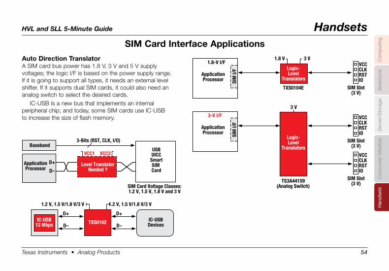
HVL and SLL 5-Minute Guide Handsets
Texas Instruments • Analog Products 54
Han
dse
tsC
omp
utin
gN
oteb
ook
Con
sum
er M
edic
alS
erve
r/S
tora
ge
SIM .Card .Interface .Applications
Auto .Direction .TranslatorA SIM card bus power has 1.8 V, 3 V and 5 V supply voltages; the logic I/F is based on the power supply range. If it is going to support all types, it needs an external level shifter. If it supports dual SIM cards, it could also need an analog switch to select the desired cards.
IC-USB is a new bus that implements an internal peripheral chip; and today, some SIM cards use IC-USB to increase the size of flash memory.
3 V1.8 V1.8-V I/F
TXS0104E SIM Slot(3 V)
VCCCLKRSTIO
Logic-Level
TranslatorsApplicationProcessor SI
M I/
F
3 V
3-V I/F
TS3A44159(Analog Switch)
Logic-Level
Translators
ApplicationProcessor SI
M I/
F
SIM Slot(3 V)
VCCCLKRSTIO
SIM Slot(3 V)
VCCCLKRSTIO
VCC1
3-Bits (RST, CLK, I/O)
VCC2
1.2 V, 1.5 V/1.8 V/3 V 1.2 V, 1.5 V/1.8 V/3 V
Level TranslatorNeeded ?
USBUICC
SmartSIM Card
SIM Card Voltage Classes:1.2 V, 1.5 V, 1.8 V and 3 V
TXS0102 IC-USBDevices
Baseband
ApplicationProcessor
D+
D–
D+
D–
D+
D–IC-USB
12 Mbps
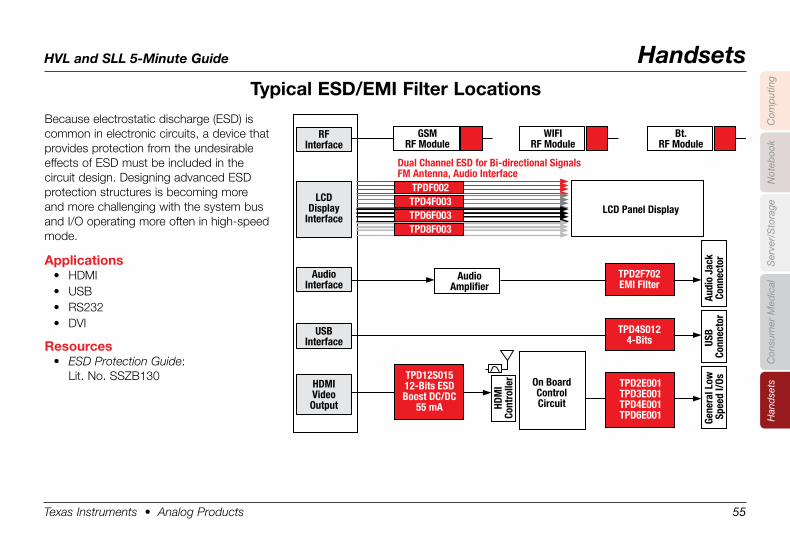
HVL and SLL 5-Minute Guide Handsets
Texas Instruments • Analog Products 55
Han
dse
tsC
omp
utin
gN
oteb
ook
Con
sum
er M
edic
alS
erve
r/S
tora
ge
Typical .ESD/EMI .Filter .Locations
Because electrostatic discharge (ESD) is common in electronic circuits, a device that provides protection from the undesirable effects of ESD must be included in the circuit design. Designing advanced ESD protection structures is becoming more and more challenging with the system bus and I/O operating more often in high-speed mode.
Applications• HDMI • USB • RS232 • DVI
Resources• ESD Protection Guide:
Lit. No. SSZB130
TPDF002
TPD12S01512-Bits ESDBoost DC/DC
55 mA
TPD2E001TPD3E001TPD4E001TPD6E001
TPD4S0124-Bits
TPD2F702EMI FIlter
TPD4F003TPD6F003TPD8F003
LCD Panel Display
Dual Channel ESD for Bi-directional SignalsFM Antenna, Audio Interface
HDM
ICo
ntro
ller
AudioAmplifier
GSMRF Module
WIFIRF Module
Bt.RF Module
On BoardControlCircuit
RFInterface
LCDDisplay
Interface
AudioInterface
USBInterface
HDMIVideoOutput
Gene
ral L
ow S
peed
I/Os
USB
Conn
ecto
rAu
dio
Jack
Conn
ecto
r
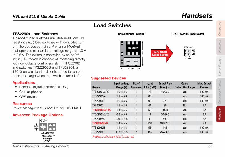
HVL and SLL 5-Minute Guide Handsets
Texas Instruments • Analog Products 56
Han
dse
tsC
omp
utin
gN
oteb
ook
Con
sum
er M
edic
alS
erve
r/S
tora
ge
TPS2290x .Load .SwitchesTPS2290x load switches are ultra-small, low ON resistance (ron) load switches with controlled turn on. The devices contain a P-channel MOSFET that operates over an input voltage range of 1.0 V to 3.6 V. The switch is controlled by an on/off input (ON), which is capable of interfacing directly with low-voltage control signals. In TPS22902 and switches TPS22902B and TPS22904, a 120-Ω on-chip load resistor is added for output quick discharge when the switch is turned off.
Applications• Personal digital assistants (PDAs)• Cellular phones• GPS devices
ResourcesPower Management Guide: Lit. No. SLVT145J
Advanced .Package .Options
Suggested .Devices
DeviceInput Voltage
Range (V)No. of
Channelsron at
3.6 V (mΩ)Output Rise Time (µs)
Quick Output Discharge
Max. Output Current
TPS22901/2/2B 1.0 to 3.6 1 78 40/220 Yes 500 mA
TPS22903/4 1.1 to 3.6 1 66 1 Yes 500 mA
TPS22906 1.0 to 3.6 1 90 220 Yes 500 mA
TPS22907 1.1 to 3.6 1 44 36 No 1 A
TPS22913B/11A 1.4 to 5.5 1 50 100/1 Yes 2 A
TPS22921/2/2B 0.9 to 3.6 1 14 30/200 Yes 2 A
TPS22924C 0.75 to 3.6 1 6 800 Yes 2 A
TPS22929B/D 1.4 to 5.5 1 110 100/3200 Yes 2 A
TPS22932B 1.1 to 3.6 1 55 165 Yes 500 mA
TPS22960 1.62 to 5.5 2 435 75 or 660 Yes 500 mA
Preview products are listed in bold red.
Load .Switches
Ball Pitch = 0.020 (0,50)Height = 0.020 (0,50)Area = 0.001 (0,65)
4-Ball WCSPNanoStar Package
(YZV)
0.035(0,90)
0.035(0,90)
™
Conventional Solution TI’s TPS22902 Load Switch
92% BoardSpace Saving
2.5 mm
N-FET
3.3
mm
N-FET
R
R
CSD25302
C
0.8 mm
TPS22902
0.8
mm
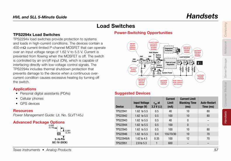
HVL and SLL 5-Minute Guide Handsets
Texas Instruments • Analog Products 57
Han
dse
tsC
omp
utin
gN
oteb
ook
Con
sum
er M
edic
alS
erve
r/S
tora
ge
TPS2294x .Load .SwitchesTPS2294x load switches provide protection to systems and loads in high-current conditions. The devices contain a 400-mΩ current-limited P-channel MOSFET that can operate over an input voltage range of 1.62 V to 5.5 V. Current is prevented from flowing when the MOSFET is off. The switch is controlled by an on/off input (ON), which is capable of interfacing directly with low-voltage control signals. The TPS2294x includes thermal shutdown protection that prevents damage to the device when a continuous over- current condition causes excessive heating by turning off the switch.
Applications• Personal digital assistants (PDAs)• Cellular phones• GPS devices
ResourcesPower Management Guide: Lit. No. SLVT145J
Advanced .Package .Options
Suggested .Devices
DeviceInput Voltage
Range (V)ron at
3.3 V (Ω)
Current Limit (mA)
Current Limit Blanking Time
(ms)Auto-Restart
Time (ms)TPS22941 1.62 to 5.5 0.5 40 10 80
TPS22942 1.62 to 5.5 0.5 100 10 80
TPS22943 1.62 to 5.5 0.5 40 0 –
TPS22944 1.62 to 5.5 0.5 100 0 –
TPS22945 1.62 to 5.5 0.5 100 10 80
TPS22946 1.62 to 5.5 0.4 155/70/30 10 70
TPS22949/A 1.62 to 4.5 0.35 100 12 70
TPS22951 2.8 to 5.3 1 600 – –
Load .Switches
FingerprintProtection
USB Power
System Power
BatteryCharging
Point-of-LoadRegulation
Cam
era
Disp
lay
Mem
ory
BatteryBypassRVP OVP
OVP/OCPbq24314
CSD75301CSD23201
Wall Adapter
Power-Switching Opportunities
Load SwitchTPS22922BTPS22903TPS22934
Load SwitchTPS22902BTPS22921TPS22960
Load SwitchTPS22922
TPS22932B
Current-LimitedLoad SwitchTPS22942/5TPS22949TPS22946
DC/DC TPS6xxxxDC/DC TPS5xxxx
LDO TPS7xxxx
Load SwitchTPS22913BCSD23201
USB CurrentLimiting
TPS2552/3
Load SwitchTPS22913BCSD75301CSD23201
Load Switches
Power-Switching .Opportunities
0.085(2,15)
0.091(2,30)
5-/6-PinSC-70 (DCK)
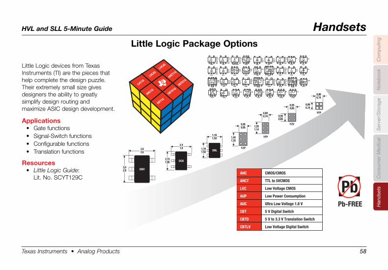
HVL and SLL 5-Minute Guide Handsets
Texas Instruments • Analog Products 58
Han
dse
tsC
omp
utin
gN
oteb
ook
Con
sum
er M
edic
alS
erve
r/S
tora
ge
Little .Logic .Package .Options
Little Logic devices from Texas Instruments (TI) are the pieces that help complete the design puzzle. Their extremely small size gives designers the ability to greatly simplify design routing and maximize ASIC design development.
Applications• Gate functions• Signal-Switch functions• Configurable functions• Translation functions
Resources• Little Logic Guide:
Lit. No. SCYT129C
45
3211G00
AHCAHCTLVCAUCAUP
45
321
AHCAHCT
1G02
LVCAUCAUP
5 4
321
AHCAHCT
1G04/1GU04
LVCAUCAUP
AHCAHCT
1G14
45
321
LVCAUCAUP
45
321
1G17
LVCAUCAUP
AHCAHCT
1G32
5 4
321
LVCAUCAUP
45
321
AHCAHCT
1G125
LVCAUCAUP
45
321
AHCAHCT
1G126
LVCAUCAUP
45
3211G240
LVCAUCAUP
45
3211G06
LVCAUCAUP
45
3211G07
LVCAUCAUP
45
321
1G79
C
CLKDD
QLVCAUCAUP
45
321D
DC
Q
CLK
1G80
LVCAUCAUP
45
321
AHCAHCT
1G08
LVCAUCAUP
45
321
AHCAHCT
1G86
LVCAUC
5 46
321
1G18
LVCAUC
45
321
1G38
1G10
5 46
321
LVC
1G11
5 46
321
LVC
1G19
5 46
321
AUCLVC
1G27
5 46
321
LVC
45
321
1G34
LVCAUP
LVC
CQS D R
1G744321
5678
Q AUCAUP
1G332
5 46
321
LVC
1G386
5 46
321
LVC
5 46
321
1G175
LVC
C1 DR Q
1G373
LVCC D
5 46
321
Q
1G374
LVCC1 D
Q
5 46
321
5 46
3211GX04
LVC
LVC
1G294321
5678
LVC
1G1234321
5678
Q
R
LVC
1G1394321
5678
1G3208
5 46
321
LVC
AUP
1G0832
5 46
321
LVC
1G157
5 46
321
PbPb-FREE
AHC CMOS/CMOS
AHCT TTL to 5VCMOS
LVC Low Voltage CMOS
AUP Low Power Consumption
AUC Ultra Low Voltage 1.8 V
CBT 5 V Digital Switch
CBTD 5 V to 3.3 V Translation Switch
CBTLV Low Voltage Digital Switch
DBV
3,02,6
3,02,8
DCK
2,41,8
2,151,85
YZP
0,950,85
1,451,35
YFP
0,800,74
1,201,14
1,701,50 DRL
1,701,50
0,950,85
0,950,85
YZV
YFP
0,800,74
0,800,74
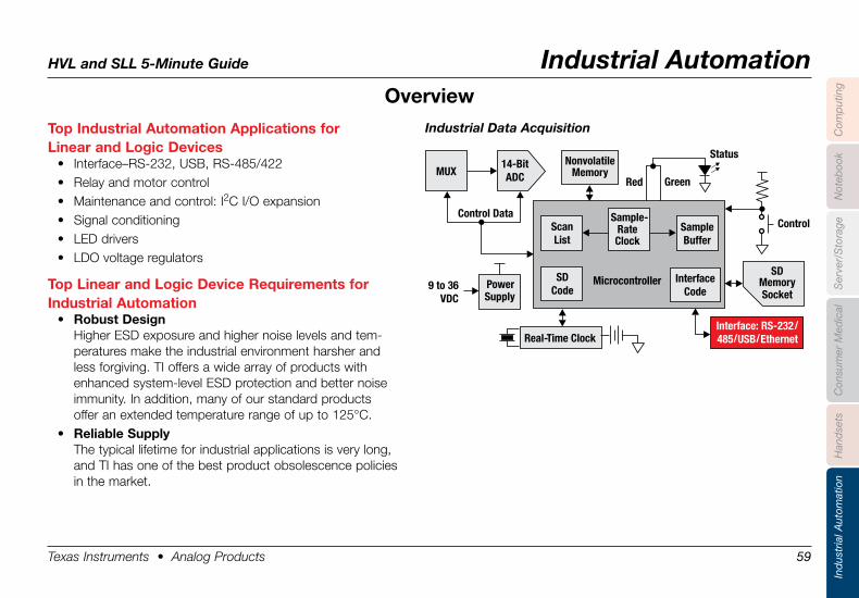
HVL and SLL 5-Minute Guide Industrial Automation
Texas Instruments • Analog Products 59
Han
dse
tsIn
dus
tria
l Aut
omat
ion
Com
put
ing
Not
eboo
kC
onsu
mer
Med
ical
Ser
ver/
Sto
rage
Top .Industrial .Automation .Applications .for . .Linear .and .Logic .Devices
• Interface–RS-232, USB, RS-485/422• Relay and motor control• Maintenance and control: I2C I/O expansion• Signal conditioning• LED drivers• LDO voltage regulators
Top .Linear .and .Logic .Device .Requirements .for . .Industrial .Automation
• Robust .DesignHigher ESD exposure and higher noise levels and tem-peratures make the industrial environment harsher and less forgiving. TI offers a wide array of products with enhanced system-level ESD protection and better noise immunity. In addition, many of our standard products offer an extended temperature range of up to 125°C.
• Reliable .SupplyThe typical lifetime for industrial applications is very long, and TI has one of the best product obsolescence policies in the market.
Control Data
Red
Status
Control
NonvolatileMemory
PowerSupply
9 to 36VDC
Interface: RS-232/485/USB/EthernetReal-Time Clock
SDMemorySocket
Green
14-BitADC
Microcontroller
ScanList
InterfaceCode
SDCode
Sample-RateClock
SampleBuffer
MUX
Industrial Data Acquisition
Overview
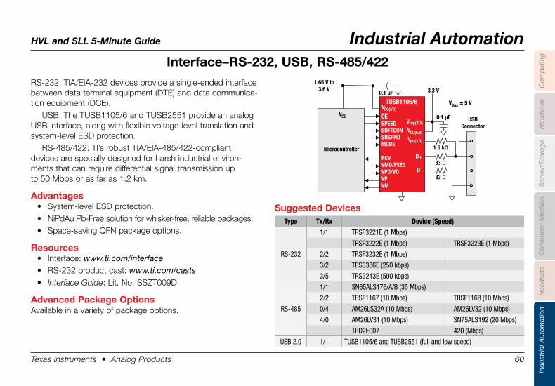
HVL and SLL 5-Minute Guide Industrial Automation
Texas Instruments • Analog Products 60
Han
dse
tsIn
dus
tria
l Aut
omat
ion
Com
put
ing
Not
eboo
kC
onsu
mer
Med
ical
Ser
ver/
Sto
rage
RS-232: TIA/EIA-232 devices provide a single-ended interface between data terminal equipment (DTE) and data communica-tion equipment (DCE).
USB: The TUSB1105/6 and TUSB2551 provide an analog USB interface, along with flexible voltage-level translation and system-level ESD protection.
RS-485/422: TI’s robust TIA/EIA-485/422-compliant devices are specially designed for harsh industrial environ-ments that can require differential signal transmission up to 50 Mbps or as far as 1.2 km.
Advantages• System-level ESD protection.• NiPdAu Pb-Free solution for whisker-free, reliable packages.• Space-saving QFN package options.
Resources• Interface: www.ti.com/interface• RS-232 product cast: www.ti.com/casts• Interface Guide: Lit. No. SSZT009D
Advanced .Package .OptionsAvailable in a variety of package options.
Interface–RS-232, .USB, .RS-485/422
Suggested .DevicesType Tx/Rx Device (Speed)
RS-232
1/1 TRSF3221E (1 Mbps)
TRSF3222E (1 Mbps) TRSF3223E (1 Mbps)
2/2 TRSF3232E (1 Mbps)
3/2 TRS3386E (250 kbps)
3/5 TRS3243E (500 kbps)
RS-485
1/1 SN65ALS176/A/B (35 Mbps)
2/2 TRSF1167 (10 Mbps) TRSF1168 (10 Mbps)
0/4 AM26LS32A (10 Mbps) AM26LV32 (10 Mbps)
4/0 AM26LV31 (10 Mbps) SN75ALS192 (20 Mbps)
TPD2E007 420 (Mbps)
USB 2.0 1/1 TUSB1105/6 and TUSB2551 (full and low speed)
Microcontroller
VCC
VCC(I/O)
1.65 V to3.6 V 3.3 V0.1 µF
0.1 µF
1.5 kΩ
V = 5 VBus
33 Ω
33 Ω
USBConnector
TUSB1105/6
V
V
V
D
D
reg(3.3)
CC(5.0)
pu(3.3)
+
-
OESPEEDSOFTCONSUSPNDMODE
RCVVMO/FSE0VPO/VOVPVM
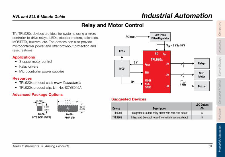
HVL and SLL 5-Minute Guide Industrial Automation
Texas Instruments • Analog Products 61
Han
dse
tsIn
dus
tria
l Aut
omat
ion
Com
put
ing
Not
eboo
kC
onsu
mer
Med
ical
Ser
ver/
Sto
rage
TI’s TPL920x devices are ideal for systems using a micro- controller to drive relays, LEDs, stepper motors, solenoids, MOSFETs, buzzers, etc. The devices can also provide microcontroller power and offer brownout protection and reset features.
Applications• Stepper motor control• Relay drivers• Microcontroller power supplies
Resources• TPL920x product cast: www.ti.com/casts• TPL920x product clip: Lit. No. SCYB045A
Advanced .Package .Options
Relay .and .Motor .Control
Suggested .Devices
Device DescriptionLDO Output
(V)TPL9201 Integrated 8-output relay driver with zero-volt detect 5
TPL9202 Integrated 8-output relay driver with brownout detect 5
V = 7 V to 18 V IN
4 kHz
5 V3
4
SPI
BO
TPL920x
VIN
I/0
I/0
I/0
EN1
MOSINCSSCLK
VOUT
LEDs
MCU
Relays
Buzzer
StepMotor
AC InputLow-Pass
Filter/Regulator
0.260(6,60)
0.260(6,60)
20-PinHTSSOP (PWP)
0.975(24,77)
0.310(7,87)
20-Pin PDIP (N)
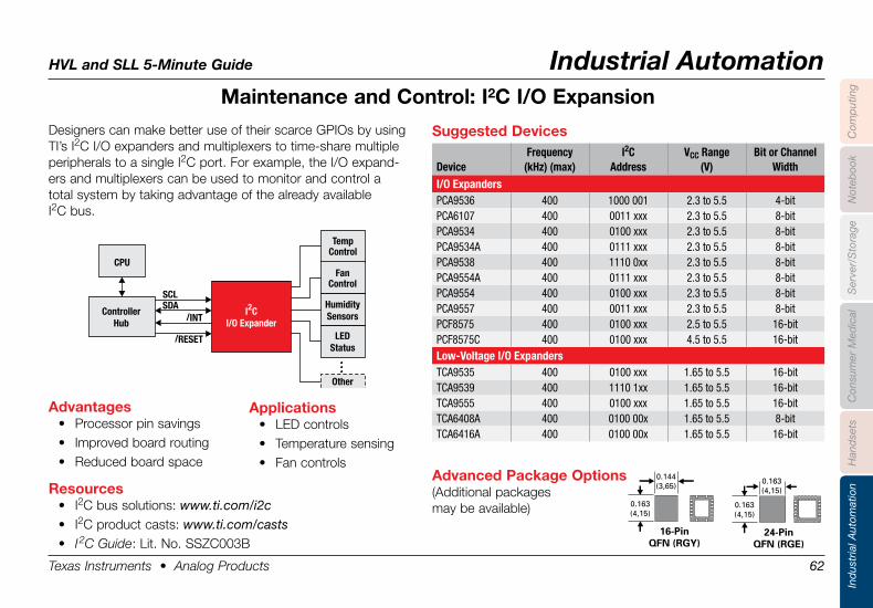
HVL and SLL 5-Minute Guide Industrial Automation
Texas Instruments • Analog Products 62
Han
dse
tsIn
dus
tria
l Aut
omat
ion
Com
put
ing
Not
eboo
kC
onsu
mer
Med
ical
Ser
ver/
Sto
rage
Designers can make better use of their scarce GPIOs by using TI’s I2C I/O expanders and multiplexers to time-share multiple peripherals to a single I2C port. For example, the I/O expand-ers and multiplexers can be used to monitor and control a total system by taking advantage of the already available I2C bus.
Applications• LED controls• Temperature sensing• Fan controls
0.144(3,65)
0.163(4,15)
16-PinQFN (RGY)
0.163(4,15)
0.163(4,15)
24-PinQFN (RGE)
/INT
/RESET
SCL
SDA
Temp
Control
Controller
Hub
CPU
Fan
Control
Humidity
Sensors
LED
Status
Other
I C
I/O Expander
2
Advantages• Processor pin savings• Improved board routing• Reduced board space
Resources• I2C bus solutions: www.ti.com/i2c• I2C product casts: www.ti.com/casts• I 2C Guide: Lit. No. SSZC003B
Advanced .Package .Options(Additional packages may be available)
Suggested .Devices
DeviceFrequency
(kHz) (max)I2C
AddressVCC Range
(V)Bit or Channel
WidthI/O ExpandersPCA9536 400 1000 001 2.3 to 5.5 4-bitPCA6107 400 0011 xxx 2.3 to 5.5 8-bitPCA9534 400 0100 xxx 2.3 to 5.5 8-bitPCA9534A 400 0111 xxx 2.3 to 5.5 8-bitPCA9538 400 1110 0xx 2.3 to 5.5 8-bitPCA9554A 400 0111 xxx 2.3 to 5.5 8-bitPCA9554 400 0100 xxx 2.3 to 5.5 8-bitPCA9557 400 0011 xxx 2.3 to 5.5 8-bitPCF8575 400 0100 xxx 2.5 to 5.5 16-bitPCF8575C 400 0100 xxx 4.5 to 5.5 16-bitLow-Voltage I/O ExpandersTCA9535 400 0100 xxx 1.65 to 5.5 16-bitTCA9539 400 1110 1xx 1.65 to 5.5 16-bitTCA9555 400 0100 xxx 1.65 to 5.5 16-bitTCA6408A 400 0100 00x 1.65 to 5.5 8-bitTCA6416A 400 0100 00x 1.65 to 5.5 16-bit
Maintenance .and .Control: .I2C .I/O .Expansion
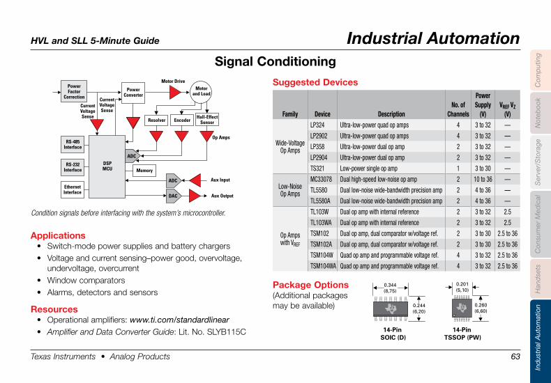
HVL and SLL 5-Minute Guide Industrial Automation
Texas Instruments • Analog Products 63
Han
dse
tsIn
dus
tria
l Aut
omat
ion
Com
put
ing
Not
eboo
kC
onsu
mer
Med
ical
Ser
ver/
Sto
rage
Signal .Conditioning
Suggested .Devices
Family Device DescriptionNo. of
Channels
PowerSupply
(V)VREF VZ
(V)
Wide-VoltageOp Amps
LP324 Ultra-low-power quad op amps 4 3 to 32 —
LP2902 Ultra-low-power quad op amps 4 3 to 32 —
LP358 Ultra-low-power dual op amp 2 3 to 32 —
LP2904 Ultra-low-power dual op amp 2 3 to 32 —
TS321 Low-power single op amp 1 3 to 30 —
Low-NoiseOp Amps
MC33078 Dual high-speed low-noise op amp 2 10 to 36 —
TL5580 Dual low-noise wide-bandwidth precision amp 2 4 to 36 —
TL5580A Dual low-noise wide-bandwidth precision amp 2 4 to 36 —
Op Ampswith VREF
TL103W Dual op amp with internal reference 2 3 to 32 2.5
TL103WA Dual op amp with internal reference 2 3 to 32 2.5
TSM102 Dual op amp, dual comparator w/voltage ref. 2 3 to 30 2.5 to 36
TSM102A Dual op amp, dual comparator w/voltage ref. 2 3 to 30 2.5 to 36
TSM104W Quad op amp and programmable voltage ref. 4 3 to 32 2.5 to 36
TSM104WA Quad op amp and programmable voltage ref. 4 3 to 32 2.5 to 36
0.344(8,75)
0.244(6,20)
14-Pin SOIC (D)
0.201(5,10)
0.260(6,60)
14-Pin TSSOP (PW)
Applications• Switch-mode power supplies and battery chargers• Voltage and current sensing–power good, overvoltage,
undervoltage, overcurrent• Window comparators• Alarms, detectors and sensors
Resources• Operational amplifiers: www.ti.com/standardlinear• Amplifier and Data Converter Guide: Lit. No. SLYB115C
PowerFactor
Correction
CurrentVoltageSense
CurrentVoltageSense
Motor DriveMotor
and Load
DSPMCU
ADC
ADC
DAC
Aux Input
Aux Output
Op Amps
PowerConverter
RS-485Interface
RS-232Interface
EthernetInterface
Memory
Hall-EffectSensorResolver Encoder
Package .Options(Additional packages may be available)
Condition signals before interfacing with the system’s microcontroller.
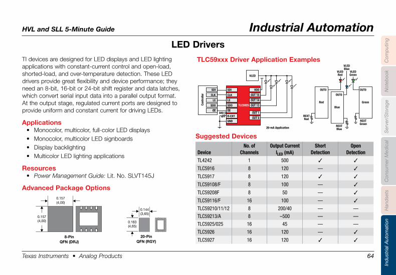
HVL and SLL 5-Minute Guide Industrial Automation
Texas Instruments • Analog Products 64
Han
dse
tsIn
dus
tria
l Aut
omat
ion
Com
put
ing
Not
eboo
kC
onsu
mer
Med
ical
Ser
ver/
Sto
rage
TI devices are designed for LED displays and LED lighting applications with constant-current control and open-load, shorted-load, and over-temperature detection. These LED drivers provide great flexibility and device performance; they need an 8-bit, 16-bit or 24-bit shift register and data latches, which convert serial input data into a parallel output format. At the output stage, regulated current ports are designed to provide uniform and constant current for driving LEDs.
Applications• Monocolor, multicolor, full-color LED displays• Monocolor, multicolor LED signboards• Display backlighting• Multicolor LED lighting applications
Resources• Power Management Guide: Lit. No. SLVT145J
Advanced .Package .Options
LED .Drivers
0.157 (4,00)
0.157 (4,00)
8-PinQFN .(DRJ)
0.144 (3,65)
0.183 (4,65)
20-PinQFN .(RGY) .
SDI
VLED
26-mA Application
Red
REXTRed
VLEDRed
VLEDGreen
VLEDBlue
REXTBlue
REXTGreen
OUT0
TLC5925
CLK
LE
SDO
VDD
OUT 15
OUT 14
OUT 13
OUT 1
OUT 0R-EXT
GND
840 OOE
Cont
rolle
r
SDI
CLK
LE
SDO
OE
Green
OUT0
Blue
OUT0
TLC59xxx .Driver .Application .Examples
Suggested .Devices
DeviceNo. of
ChannelsOutput Current
ILED (mA)Short
DetectionOpen
Detection
TL4242 1 500 3 3
TLC5916 8 120 — 3
TLC5917 8 120 3 3
TLC59108/F 8 100 — 3
TLC59208F 8 50 — 3
TLC59116/F 16 100 — 3
TLC59210/11/12 8 200/40 — —
TLC59213/A 8 –500 — —
TLC5925/025 16 45 — —
TLC5926 16 120 — 3
TLC5927 16 120 3 3
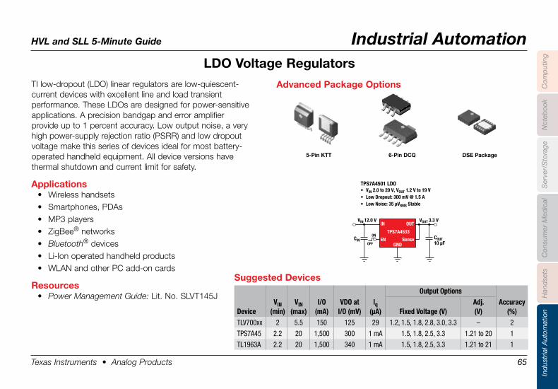
HVL and SLL 5-Minute Guide Industrial Automation
Texas Instruments • Analog Products 65
Han
dse
tsIn
dus
tria
l Aut
omat
ion
Com
put
ing
Not
eboo
kC
onsu
mer
Med
ical
Ser
ver/
Sto
rage
TI low-dropout (LDO) linear regulators are low-quiescent- current devices with excellent line and load transient performance. These LDOs are designed for power-sensitive applications. A precision bandgap and error amplifier provide up to 1 percent accuracy. Low output noise, a very high power-supply rejection ratio (PSRR) and low dropout voltage make this series of devices ideal for most battery-operated handheld equipment. All device versions have thermal shutdown and current limit for safety.
Applications• Wireless handsets• Smartphones, PDAs• MP3 players• ZigBee® networks• Bluetooth® devices• Li-Ion operated handheld products• WLAN and other PC add-on cards
Resources• Power Management Guide: Lit. No. SLVT145J
LDO .Voltage .Regulators
Suggested .DevicesOutput Options
DeviceVIN
(min)VIN
(max)I/O
(mA)VDO at
I/O (mV)lq
(µA) Fixed Voltage (V)Adj. (V)
Accuracy (%)
TLV700xx 2 5.5 150 125 29 1.2, 1.5, 1.8, 2.8, 3.0, 3.3 – 2
TPS7A45 2.2 20 1,500 300 1 mA 1.5, 1.8, 2.5, 3.3 1.21 to 20 1
TL1963A 2.2 20 1,500 340 1 mA 1.5, 1.8, 2.5, 3.3 1.21 to 21 1
COUT10 µF
CIN
VIN 12.0 V VOUT 3.3 V
TPS7A4501 LDO• VIN 2.0 to 20 V, VOUT 1.2 V to 19 V• Low Dropout: 300 mV @ 1.5 A• Low Noise: 35 µVRMS Stable
ON
OFF
IN
EN
OUT
TPS7A4533
SenseGND
Advanced .Package .Options
5-Pin .KTT 6-Pin .DCQ DSE .Package
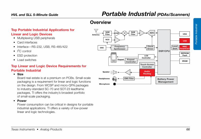
HVL and SLL 5-Minute Guide Portable Industrial (PDAs/Scanners)
Texas Instruments • Analog Products 66
Por
tab
le In
dus
tria
l
Top .Portable .Industrial .Applications .for . .Linear .and .Logic .Devices
• Multiplexing USB peripherals• Card interfaces• Interface—RS-232, USB, RS-485/422• I2C control• ESD protection• Load switches
Top .Linear .and .Logic .Device .Requirements .for . .Portable .Industrial
• SizeBoard real estate is at a premium on PCBs. Small-scale packaging is a requirement for linear and logic functions on the design. From WCSP and micro-QFN packages to industry-standard SC-70 and SOT-23 leadframe packages, TI offers the industry’s broadest portfolio of small-scale packaging.
• PowerPower consumption can be critical in designs for portable industrial applications. TI offers a variety of low-power linear and logic technologies.
Overview
Touch-ScreenController
Battery PowerManagement
AudioRouting
DSP/CPU
Headphones
Microphone
Speaker
Antenna
ClockDriver
SAW Filter IrDA
USB
MMCSmartCard
EEPROMFlash
SRAM
LCDController
VCO
OSC
SAWFilter
ADCLNA
Keypad Keypad Controller
EMI Filter
LevelShift
FrequencySynthesizer
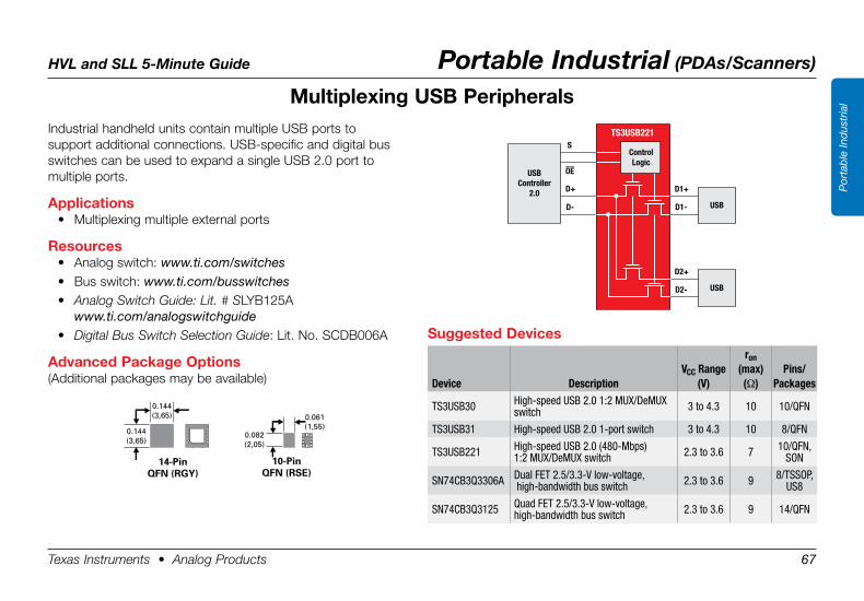
HVL and SLL 5-Minute Guide Portable Industrial (PDAs/Scanners)
Texas Instruments • Analog Products 67
Por
tab
le In
dus
tria
l
Industrial handheld units contain multiple USB ports to support additional connections. USB-specific and digital bus switches can be used to expand a single USB 2.0 port to multiple ports.
Applications• Multiplexing multiple external ports
Resources• Analog switch: www.ti.com/switches• Bus switch: www.ti.com/busswitches• Analog Switch Guide: Lit. # SLYB125A
www.ti.com/analogswitchguide• Digital Bus Switch Selection Guide: Lit. No. SCDB006A
Advanced .Package .Options(Additional packages may be available)
Multiplexing .USB .Peripherals
D1+
D2+
D+
D1-
D2-
D-
S
OE
TS3USB221
USBController
2.0USB
USB
ControlLogic
Suggested .Devices
Device DescriptionVCC Range
(V)
ron (max)(Ω)
Pins/Packages
TS3USB30 High-speed USB 2.0 1:2 MUX/DeMUX switch 3 to 4.3 10 10/QFN
TS3USB31 High-speed USB 2.0 1-port switch 3 to 4.3 10 8/QFN
TS3USB221 High-speed USB 2.0 (480-Mbps) 1:2 MUX/DeMUX switch 2.3 to 3.6 7 10/QFN,
SON
SN74CB3Q3306A Dual FET 2.5/3.3-V low-voltage, high-bandwidth bus switch 2.3 to 3.6 9 8/TSSOP,
US8
SN74CB3Q3125 Quad FET 2.5/3.3-V low-voltage, high-bandwidth bus switch 2.3 to 3.6 9 14/QFN
0.144(3,65)
0.144(3,65)
14-PinQFN (RGY)
0.061(1,55)
0.082(2,05)
10-PinQFN (RSE)
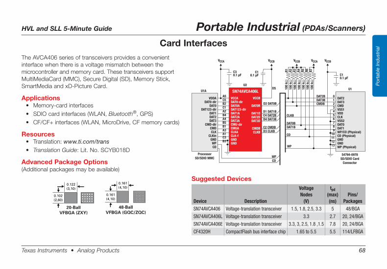
HVL and SLL 5-Minute Guide Portable Industrial (PDAs/Scanners)
Texas Instruments • Analog Products 68
Por
tab
le In
dus
tria
lCard InterfacesTheAVCA406seriesoftransceiversprovidesaconvenientinterface when there is a voltage mismatch between the microcontroller and memory card. These transceivers support MultiMediaCard (MMC), Secure Digital (SD), Memory Stick, SmartMedia and xD-Picture Card.
Applications• Memory-cardinterfaces• SDIOcardinterfaces(WLAN,Bluetooth®, GPS)• CF/CF+interfaces(WLAN,MicroDrive,CFmemorycards)
Resources• Translation:www.ti.com/trans• Translation Guide:Lit.No.SCYB018D
Advanced Package Options(Additional packages may be available)
D2 DAT0B
CLKB
0
1
2
3
4
5
6
7
8
9
10
11
12
13
CD
WP
DAT0B
DAT1B
DAT2B
DAT3B
CMDB
U1AU1
Processor
SD/SDIO MMC
54794-0978
SD/SDIO Card
Connector
SN74AVCA406L
U2
VCCA
C30.1 µF
C10.1 µF C1
0.1 µF
VCCB VCCB VCCBVCCA
D5
R1
R2
R3
R4
R5
R6
R7
WP
CD
A5
C5
B2
C1
A2
B4
A4
B5
B1
A3
A1
C3
B3
D1 DAT1B
C4 DAT2B
D4 DAT3B
C2 CMDB
D3 CLKB
VCCA
DAT0-dir
DAT0A
DAT123-dir
DAT1A
DAT2A
DAT3A
CMU-dir
CMUA
CLKA
CLK-f
GND
GND
DAT2
DAT3
CMD
VSS1
VDD
CLK
DAT0
DAT1
CD (Physical)
GND
GND
VSS2
WP/CO (Physical)
WP (Physical)
VDDA
DAT0-dir
DAT0
DAT123-dir
DAT1
DAT2
DAT3
CMD-dir
CMD
CLK
CLKin
GND
WP
CD
VCCB
DAT0R
DAT1D
DAT2D
DAT3D
CMDB
CLKB
10
0 k
Ω1
00
k
10
0 k
10
0 k
10
0 k
10
0 k
10
0 k
Ω Ω Ω Ω Ω Ω
Suggested Devices
Device Description
VoltageNodes
(V)
tpd(max)(ns)
Pins/Packages
SN74AVCA406 Voltage-translation transceiver 1.5, 1.8, 2.5, 3.3 5 48/BGA
SN74AVCA406L Voltage-translation transceiver 3.3 2.7 20, 24/BGA
SN74AVCA406E Voltage-translation transceiver 3.3, 3, 2.5, 1.8 ,1.5 7.8 20, 24/BGA
CF4320H CompactFlash bus interface chip 1.65 to 5.5 5.5 114/LFBGA
0.122(3,10)
0.102(2,60)
20-BallVFBGA (ZXY)
0.161(4,10)
0.161(4,10)
48-BallVFBGA (GQC/ZQC)
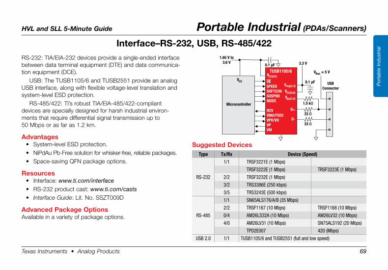
HVL and SLL 5-Minute Guide Portable Industrial (PDAs/Scanners)
Texas Instruments • Analog Products 69
Por
tab
le In
dus
tria
lInterface–RS-232, .USB, .RS-485/422RS-232: TIA/EIA-232 devices provide a single-ended interface between data terminal equipment (DTE) and data communica-tion equipment (DCE).
USB: The TUSB1105/6 and TUSB2551 provide an analog USB interface, along with flexible voltage-level translation and system-level ESD protection.
RS-485/422: TI’s robust TIA/EIA-485/422-compliant devices are specially designed for harsh industrial environ-ments that require differential signal transmission up to 50 Mbps or as far as 1.2 km.
Advantages• System-level ESD protection.• NiPdAu Pb-Free solution for whisker-free, reliable packages.• Space-saving QFN package options.
Resources• Interface: www.ti.com/interface• RS-232 product cast: www.ti.com/casts• Interface Guide: Lit. No. SSZT009D
Advanced .Package .OptionsAvailable in a variety of package options.
Microcontroller
VCC
VCC(I/O)
1.65 V to3.6 V 3.3 V0.1 µF
0.1 µF
1.5 kΩ
V = 5 VBus
33 Ω
33 Ω
USBConnector
TUSB1105/6
V
V
V
D
D
reg(3.3)
CC(5.0)
pu(3.3)
+
-
OESPEEDSOFTCONSUSPNDMODE
RCVVMO/FSE0VPO/VOVPVM
Suggested .DevicesType Tx/Rx Device (Speed)
RS-232
1/1 TRSF3221E (1 Mbps)
TRSF3222E (1 Mbps) TRSF3223E (1 Mbps)
2/2 TRSF3232E (1 Mbps)
3/2 TRS3386E (250 kbps)
3/5 TRS3243E (500 kbps)
RS-485
1/1 SN65ALS176/A/B (35 Mbps)
2/2 TRSF1167 (10 Mbps) TRSF1168 (10 Mbps)
0/4 AM26LS32A (10 Mbps) AM26LV32 (10 Mbps)
4/0 AM26LV31 (10 Mbps) SN75ALS192 (20 Mbps)
TPD2E007 420 (Mbps)
USB 2.0 1/1 TUSB1105/6 and TUSB2551 (full and low speed)
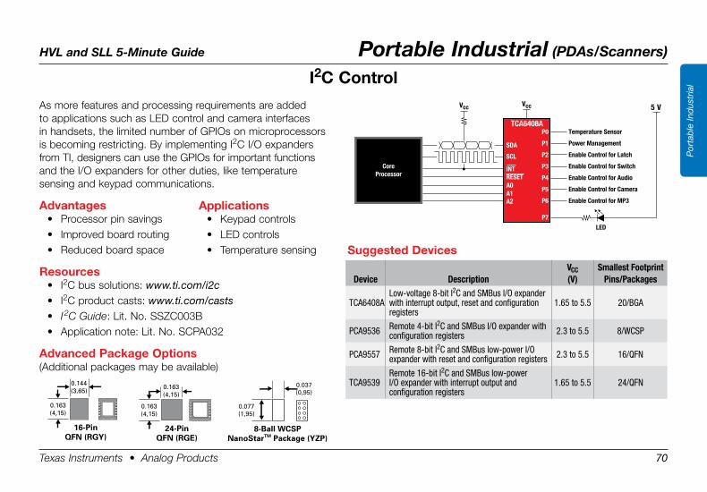
HVL and SLL 5-Minute Guide Portable Industrial (PDAs/Scanners)
Texas Instruments • Analog Products 70
Por
tab
le In
dus
tria
lI2C .Control
As more features and processing requirements are added to applications such as LED control and camera interfaces in handsets, the limited number of GPIOs on microprocessors is becoming restricting. By implementing I2C I/O expanders from TI, designers can use the GPIOs for important functions and the I/O expanders for other duties, like temperature sensing and keypad communications.
Advantages• Processor pin savings• Improved board routing• Reduced board space
Resources• I2C bus solutions: www.ti.com/i2c• I2C product casts: www.ti.com/casts• I 2C Guide: Lit. No. SSZC003B• Application note: Lit. No. SCPA032
Advanced .Package .Options(Additional packages may be available)
Vcc Vcc 5 V
SDA
SCL
INT
A0 A1 A2
P0
P1
P2
P3
P4
P5
P6
LED
P7
TCA6408ATemperature Sensor
Power Management
Enable Control for Latch
Enable Control for Switch
Enable Control for Audio
Enable Control for Camera
Enable Control for MP3
RESET
CoreProcessor
0.037(0,95)
0.077(1,95)
8-Ball WCSPNanoStarTM Package (YZP)
0.144(3,65)
0.163(4,15)
16-PinQFN (RGY)
0.163(4,15)
0.163(4,15)
24-PinQFN (RGE)
Applications• Keypad controls• LED controls• Temperature sensing Suggested .Devices
Device DescriptionVCC(V)
Smallest FootprintPins/Packages
TCA6408ALow-voltage 8-bit I2C and SMBus I/O expander with interrupt output, reset and configuration registers
1.65 to 5.5 20/BGA
PCA9536 Remote 4-bit I2C and SMBus I/O expander with configuration registers 2.3 to 5.5 8/WCSP
PCA9557 Remote 8-bit I2C and SMBus low-power I/O expander with reset and configuration registers 2.3 to 5.5 16/QFN
TCA9539Remote 16-bit I2C and SMBus low-power I/O expander with interrupt output and configuration registers
1.65 to 5.5 24/QFN
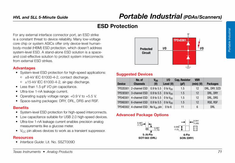
HVL and SLL 5-Minute Guide Portable Industrial (PDAs/Scanners)
Texas Instruments • Analog Products 71
Por
tab
le In
dus
tria
lESD .Protection
Protected
Circuit
I/O I/O
TPDxE001
0.067(1,70)
0.067(1,70)
5-/6-PinSOT-563 (DRL)
0.041(1,05)
0.059(1,5)
6-Pin SON (DRY)
Advanced .Package .Options
For any external interface connector port, an ESD strike is a constant threat to device reliability. Many low-voltage core chip or system ASICs offer only device-level human-body-model (HBM) ESD protection, which doesn’t address system-level ESD. A stand-alone ESD solution is a space- and cost-effective solution to protect system interconnects from external ESD strikes.
Advantages• System-level ESD protection for high-speed applications:
• ±8-kV IEC 61000-4-2, contact discharge.• ±15-kV IEC 61000-4-2, air-gap discharge.
• Less than 1.5-pF I/O pin capacitance.• Ultra-low 1-nA leakage current.• Operating supply voltage range: +0.9 V to +5.5 V.• Space-saving packages: DRY, DRL, DRS and RSF.
Benefits• System-level ESD protection for high-speed interconnects.• Low capacitance suitable for USB 2.0 high-speed devices.• Ultra-low 1-nA leakage current enables precision analog
measurements like a glucose meter.• VCC pin allows devices to work as a transient suppressor.
Resources• Interface Guide: Lit. No. SSZT009D
Suggested .Devices
DeviceNo. of
ChannelsVDD(V)
I/OLevel (V)
Cap, Resistor(pF)
VBR(min) (V) Packages
TPD2E001 2-channel ESD 0.9 to 5.5 0 to VDD 1.5 12 DRL, DRY, DZD
TPD3E001 3-channel ESD 0.9 to 5.5 0 to VDD 1.5 12 DRL, DRY
TPD4E001 4-channel ESD 0.9 to 5.5 0 to VDD 1.5 12 DRL, DRS
TPD6E001 6-channel ESD 0.9 to 5.5 0 to VDD 1.5 12 RSE, RSF
TPD4E002 4-channel ESD No VDD pin 0 to 6 11 6 DRL
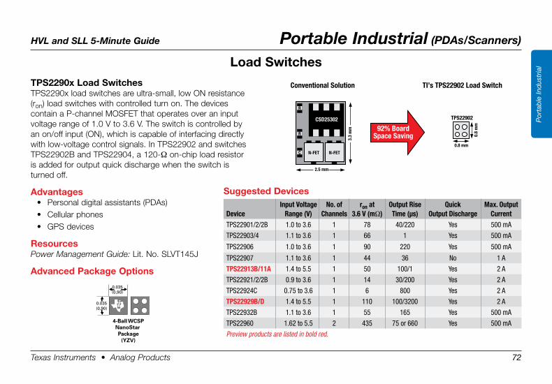
HVL and SLL 5-Minute Guide Portable Industrial (PDAs/Scanners)
Texas Instruments • Analog Products 72
Por
tab
le In
dus
tria
l
TPS2290x .Load .SwitchesTPS2290x load switches are ultra-small, low ON resistance (ron) load switches with controlled turn on. The devices contain a P-channel MOSFET that operates over an input voltage range of 1.0 V to 3.6 V. The switch is controlled by an on/off input (ON), which is capable of interfacing directly with low-voltage control signals. In TPS22902 and switches TPS22902B and TPS22904, a 120-Ω on-chip load resistor is added for output quick discharge when the switch is turned off.
Advantages• Personal digital assistants (PDAs)• Cellular phones• GPS devices
ResourcesPower Management Guide: Lit. No. SLVT145J
Advanced .Package .Options
Load .Switches
Ball Pitch = 0.020 (0,50)Height = 0.020 (0,50)Area = 0.001 (0,65)
4-Ball WCSPNanoStar Package
(YZV)
0.035(0,90)
0.035(0,90)
Conventional Solution TI’s TPS22902 Load Switch
92% BoardSpace Saving
2.5 mm
N-FET
3.3
mm
N-FET
R
R
CSD25302
C
0.8 mm
TPS22902
0.8
mm
Suggested .Devices
DeviceInput Voltage
Range (V)No. of
Channelsron at
3.6 V (mΩ)Output Rise Time (µs)
Quick Output Discharge
Max. Output Current
TPS22901/2/2B 1.0 to 3.6 1 78 40/220 Yes 500 mA
TPS22903/4 1.1 to 3.6 1 66 1 Yes 500 mA
TPS22906 1.0 to 3.6 1 90 220 Yes 500 mA
TPS22907 1.1 to 3.6 1 44 36 No 1 A
TPS22913B/11A 1.4 to 5.5 1 50 100/1 Yes 2 A
TPS22921/2/2B 0.9 to 3.6 1 14 30/200 Yes 2 A
TPS22924C 0.75 to 3.6 1 6 800 Yes 2 A
TPS22929B/D 1.4 to 5.5 1 110 100/3200 Yes 2 A
TPS22932B 1.1 to 3.6 1 55 165 Yes 500 mA
TPS22960 1.62 to 5.5 2 435 75 or 660 Yes 500 mA
Preview products are listed in bold red.
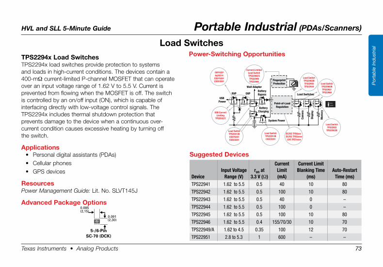
HVL and SLL 5-Minute Guide Portable Industrial (PDAs/Scanners)
Texas Instruments • Analog Products 73
Por
tab
le In
dus
tria
l
TPS2294x .Load .SwitchesTPS2294x load switches provide protection to systems and loads in high-current conditions. The devices contain a 400-mΩ current-limited P-channel MOSFET that can operate over an input voltage range of 1.62 V to 5.5 V. Current is prevented from flowing when the MOSFET is off. The switch is controlled by an on/off input (ON), which is capable of interfacing directly with low-voltage control signals. The TPS2294x includes thermal shutdown protection that prevents damage to the device when a continuous over- current condition causes excessive heating by turning off the switch.
Applications• Personal digital assistants (PDAs)• Cellular phones• GPS devices
ResourcesPower Management Guide: Lit. No. SLVT145J
Advanced .Package .Options
Suggested .Devices
DeviceInput Voltage
Range (V)ron at
3.3 V (Ω)
Current Limit (mA)
Current Limit Blanking Time
(ms)Auto-Restart
Time (ms)TPS22941 1.62 to 5.5 0.5 40 10 80
TPS22942 1.62 to 5.5 0.5 100 10 80
TPS22943 1.62 to 5.5 0.5 40 0 –
TPS22944 1.62 to 5.5 0.5 100 0 –
TPS22945 1.62 to 5.5 0.5 100 10 80
TPS22946 1.62 to 5.5 0.4 155/70/30 10 70
TPS22949/A 1.62 to 4.5 0.35 100 12 70
TPS22951 2.8 to 5.3 1 600 – –
Load .Switches
FingerprintProtection
USB Power
System Power
BatteryCharging
Point-of-LoadRegulation
Cam
era
Disp
lay
Mem
ory
BatteryBypassRVP OVP
OVP/OCPbq24314
CSD75301CSD23201
Wall Adapter
Power-Switching Opportunities
Load SwitchTPS22922BTPS22903TPS22934
Load SwitchTPS22902BTPS22921TPS22960
Load SwitchTPS22922
TPS22932B
Current-LimitedLoad SwitchTPS22942/5TPS22949TPS22946
DC/DC TPS6xxxDC/DC TPS5xxxx
LDO TPS7xxxx
Load SwitchTPS22913BCSD23201
USB CurrentLimiting
TPS2552/3
Load SwitchTPS22913BCSD75301CSD23201
Load Switches
Power-Switching .Opportunities
0.085(2,15)
0.091(2,30)
5-/6-PinSC-70 (DCK)
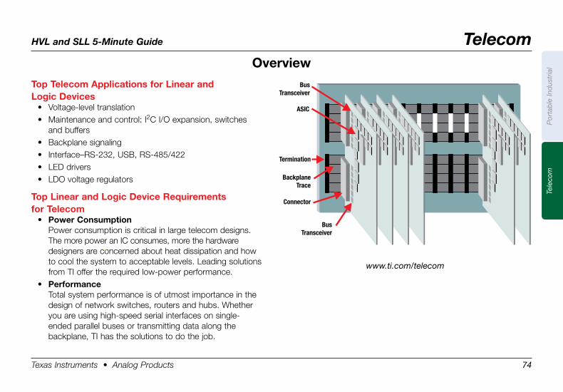
HVL and SLL 5-Minute Guide Telecom
Texas Instruments • Analog Products 74
Por
tab
le In
dus
tria
lTe
leco
m
Top .Telecom .Applications .for .Linear .and . .Logic .Devices
• Voltage-level translation• Maintenance and control: I2C I/O expansion, switches
and buffers• Backplane signaling• Interface–RS-232, USB, RS-485/422• LED drivers• LDO voltage regulators
Top .Linear .and .Logic .Device .Requirements . .for .Telecom
• Power .ConsumptionPower consumption is critical in large telecom designs. The more power an IC consumes, more the hardware designers are concerned about heat dissipation and how to cool the system to acceptable levels. Leading solutions from TI offer the required low-power performance.
• PerformanceTotal system performance is of utmost importance in the design of network switches, routers and hubs. Whether you are using high-speed serial interfaces on single- ended parallel buses or transmitting data along the backplane, TI has the solutions to do the job.
Termination
Backplane
Trace
Connector
ASIC
Bus
Transceiver
Bus
Transceiver
Overview
www.ti.com/telecom
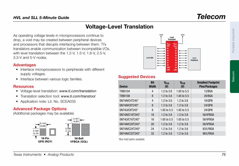
HVL and SLL 5-Minute Guide Telecom
Texas Instruments • Analog Products 75
Por
tab
le In
dus
tria
lTe
leco
m
Voltage-Level .Translation1.8 V 3.3 V
Level
Translator
V
DIR
A1
A2
A3
A4
A5
A6
A7
A8
GND
GND
CCA V
V
B1
B2
B3
B4
B5
B6
B7
B8
GND
CCB
CCB
OE
3.3-V
Peripheral
1.8-V CPU
As operating voltage levels in microprocessors continue to drop, a void may be created between peripheral devices and processors that disrupts interfacing between them. TI’s translators enable communication between incompatible I/Os, with level translation between the 1.2-V, 1.5-V, 1.8-V, 2.5-V, 3.3-V and 5-V nodes.
Advantages• Interface microprocessors to peripherals with different
supply voltages.• Interface between various logic families.
Resources• Voltage-level translation: www.ti.com/translation• Translation selection tool: www.ti.com/transtool• Application note: Lit. No. SCEA035
Advanced .Package .Options(Additional packages may be available)
0.181(4,60)
0.280(7,10)
56-BallVFBGA (GQL)
0.144(3,65)
0.163(4,15)
16-PinQFN (RGY)
Suggested .Devices
DeviceBit
WidthVCCA(V)
VCCB(V)
Smallest FootprintPins/Packages
TXB0104 4 1.2 to 3.6 1.65 to 5.5 12/BGA
TXB0108 8 1.2 to 3.6 1.65 to 5.5 20/BGA
SN74AVC4T245* 4 1.2 to 3.6 1.2 to 3.6 16/QFN
SN74AVC8T245* 8 1.2 to 3.6 1.2 to 3.6 24/QFN
SN74LVC8T245* 8 1.65 to 5.5 1.65 to 5.5 24/QFN
SN74AVC16T245* 16 1.2 to 3.6 1.2 to 3.6 56/VFBGA
SN74LVC16T245* 16 1.65 to 5.5 1.65 to 5.5 56/VFBGA
SN74AVC20T245* 20 1.2 to 3.6 1.2 to 3.6 56/VFBGA
SN74AVC24T245* 24 1.2 to 3.6 1.2 to 3.6 83/LFBGA
SN74AVC32T245* 32 1.2 to 3.6 1.2 to 3.6 96/LFBGA
*Bus-hold option available.
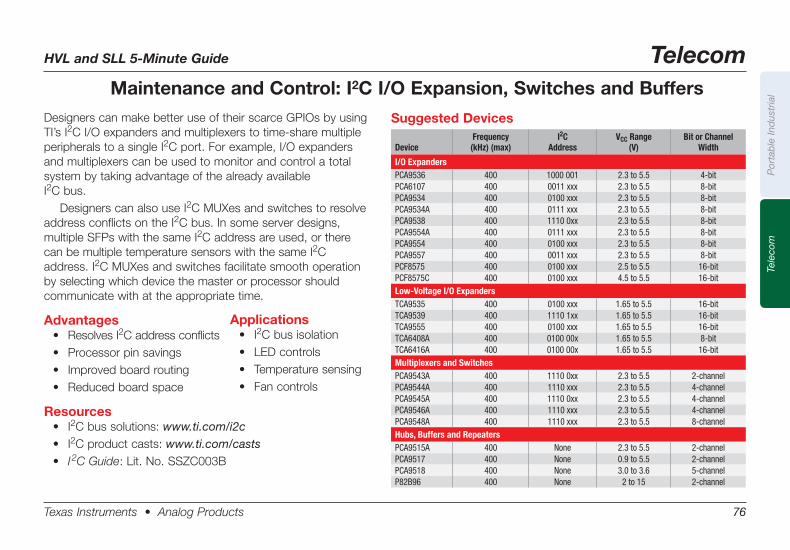
HVL and SLL 5-Minute Guide Telecom
Texas Instruments • Analog Products 76
Por
tab
le In
dus
tria
lTe
leco
m
Maintenance and Control: I2C I/O Expansion, Switches and Buffers
Applications• I2C bus isolation• LEDcontrols• Temperaturesensing• Fancontrols
Designers can make better use of their scarce GPIOs by using TI’s I2C I/O expanders and multiplexers to time-share multiple peripherals to a single I2C port. For example, I/O expanders and multiplexers can be used to monitor and control a total system by taking advantage of the already available I2C bus.
Designers can also use I2C MUXes and switches to resolve address conflicts on the I2C bus. In some server designs, multiple SFPs with the same I2C address are used, or there can be multiple temperature sensors with the same I2C address. I2C MUXes and switches facilitate smooth operation by selecting which device the master or processor should communicate with at the appropriate time.
Advantages• ResolvesI2C address conflicts• Processorpinsavings• Improvedboardrouting• Reducedboardspace
Resources• I2C bus solutions: www.ti.com/i2c• I2C product casts: www.ti.com/casts• I 2C Guide: Lit. No. SSZC003B
Suggested Devices
DeviceFrequency
(kHz) (max)I2C
AddressVCC Range
(V)Bit or Channel
Width
I/O ExpandersPCA9536 400 1000 001 2.3 to 5.5 4-bitPCA6107 400 0011 xxx 2.3 to 5.5 8-bitPCA9534 400 0100 xxx 2.3 to 5.5 8-bitPCA9534A 400 0111 xxx 2.3 to 5.5 8-bitPCA9538 400 1110 0xx 2.3 to 5.5 8-bitPCA9554A 400 0111 xxx 2.3 to 5.5 8-bitPCA9554 400 0100 xxx 2.3 to 5.5 8-bitPCA9557 400 0011 xxx 2.3 to 5.5 8-bitPCF8575 400 0100 xxx 2.5 to 5.5 16-bitPCF8575C 400 0100 xxx 4.5 to 5.5 16-bitLow-Voltage I/O ExpandersTCA9535 400 0100 xxx 1.65 to 5.5 16-bitTCA9539 400 1110 1xx 1.65 to 5.5 16-bitTCA9555 400 0100 xxx 1.65 to 5.5 16-bitTCA6408A 400 0100 00x 1.65 to 5.5 8-bitTCA6416A 400 0100 00x 1.65 to 5.5 16-bitMultiplexers and SwitchesPCA9543A 400 1110 0xx 2.3 to 5.5 2-channelPCA9544A 400 1110 xxx 2.3 to 5.5 4-channelPCA9545A 400 1110 0xx 2.3 to 5.5 4-channelPCA9546A 400 1110 xxx 2.3 to 5.5 4-channelPCA9548A 400 1110 xxx 2.3 to 5.5 8-channelHubs, Buffers and RepeatersPCA9515A 400 None 2.3 to 5.5 2-channelPCA9517 400 None 0.9 to 5.5 2-channelPCA9518 400 None 3.0 to 3.6 5-channelP82B96 400 None 2 to 15 2-channel
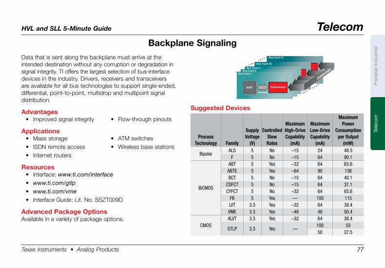
HVL and SLL 5-Minute Guide Telecom
Texas Instruments • Analog Products 77
Por
tab
le In
dus
tria
lTe
leco
m
Suggested .Devices
ProcessTechnology Family
SupplyVoltage
(V)
ControlledSlewRates
MaximumHigh-DriveCapability
(mA)
MaximumLow-DriveCapability
(mA)
Maximum Power
Consumptionper Output
(mW)
BipolarALS 5 No –15 24 48.5
F 5 No –15 64 90.1
BiCMOS
ABT 5 Yes –32 64 65.6ABTE 5 Yes –64 90 136BCT 5 No –15 64 40.1
CDFCT 5 No –15 64 37.1CYFCT 5 No –32 64 65.6
FB 5 Yes — 100 115LVT 3.3 Yes –32 64 38.4VME 3.3 Yes –48 48 50.4
CMOSALVT 3.3 Yes –32 64 38.4
GTLP 3.3 Yes —100 5550 27.5
Backplane .SignalingData that is sent along the backplane must arrive at the intended destination without any corruption or degradation in signal integrity. TI offers the largest selection of bus-interface devices in the industry. Drivers, receivers and transceivers are available for all bus technologies to support single-ended, differential, point-to-point, multidrop and multipoint signal distribution.
Advantages• Improved signal integrity • Flow-through pinouts
Applications• Mass storage • ATM switches• ISDN remote access • Wireless base stations• Internet routers
Resources• Interface: www.ti.com/interface• www.ti.com/gtlp• www.ti.com/vme• Interface Guide: Lit. No. SSZT009D
Advanced .Package .OptionsAvailable in a variety of package options.
Bus Card 1 Bus Card 2
Bus Card 3
Bus Card 10
Bus Card 21
ASIC Transceivers
Interface
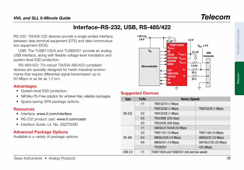
HVL and SLL 5-Minute Guide Telecom
Texas Instruments • Analog Products 78
Por
tab
le In
dus
tria
lTe
leco
m
Interface–RS-232, .USB, .RS-485/422RS-232: TIA/EIA-232 devices provide a single-ended interface between data terminal equipment (DTE) and data communica-tion equipment (DCE).
USB: The TUSB1105/6 and TUSB2551 provide an analog USB interface, along with flexible voltage-level translation and system-level ESD protection.
RS-485/422: TI’s robust TIA/EIA-485/422-compliant devices are specially designed for harsh industrial environ-ments that require differential signal transmission up to 50 Mbps or as far as 1.2 km.
Advantages• System-level ESD protection.• NiPdAu Pb-Free solution for whisker-free, reliable packages.• Space-saving QFN package options.
Resources• Interface: www.ti.com/interface• RS-232 product cast: www.ti.com/casts• Interface Guide: Lit. No. SSZT009D
Advanced .Package .OptionsAvailable in a variety of package options.
Microcontroller
VCC
VCC(I/O)
1.65 V to3.6 V 3.3 V0.1 µF
0.1 µF
1.5 kΩ
V = 5 VBus
33 Ω
33 Ω
USBConnector
TUSB1105/6
V
V
V
D
D
reg(3.3)
CC(5.0)
pu(3.3)
+
-
OESPEEDSOFTCONSUSPNDMODE
RCVVMO/FSE0VPO/VOVPVM
Suggested .DevicesType Tx/Rx Device (Speed)
RS-232
1/1 TRSF3221E (1 Mbps)
TRSF3222E (1 Mbps) TRSF3223E (1 Mbps)
2/2 TRSF3232E (1 Mbps)
3/2 TRS3386E (250 kbps)
3/5 TRS3243E (500 kbps)
RS-485
1/1 SN65ALS176/A/B (35 Mbps)
2/2 TRSF1167 (10 Mbps) TRSF1168 (10 Mbps)
0/4 AM26LS32A (10 Mbps) AM26LV32 (10 Mbps)
4/0 AM26LV31 (10 Mbps) SN75ALS192 (20 Mbps)
TPD2E007 420 (Mbps)
USB 2.0 1/1 TUSB1105/6 and TUSB2551 (full and low speed)
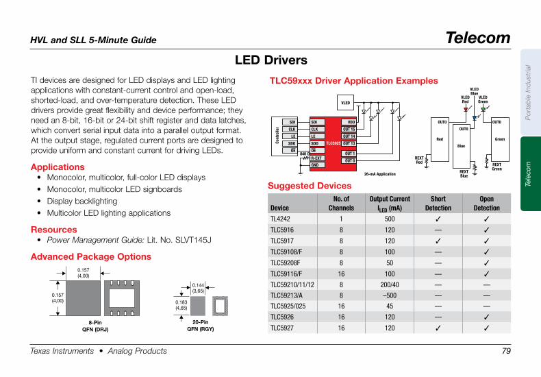
HVL and SLL 5-Minute Guide Telecom
Texas Instruments • Analog Products 79
Por
tab
le In
dus
tria
lTe
leco
m
TI devices are designed for LED displays and LED lighting applications with constant-current control and open-load, shorted-load, and over-temperature detection. These LED drivers provide great flexibility and device performance; they need an 8-bit, 16-bit or 24-bit shift register and data latches, which convert serial input data into a parallel output format. At the output stage, regulated current ports are designed to provide uniform and constant current for driving LEDs.
Applications• Monocolor, multicolor, full-color LED displays• Monocolor, multicolor LED signboards• Display backlighting• Multicolor LED lighting applications
Resources• Power Management Guide: Lit. No. SLVT145J
Advanced .Package .Options
LED .Drivers
0.157 (4,00)
8-PinQFN .(DRJ)
0.144 (3,65)
0.183 (4,65)
20-PinQFN .(RGY) .
SDI
VLED
26-mA Application
Red
REXTRed
VLEDRed
VLEDGreen
VLEDBlue
REXTBlue
REXTGreen
OUT0
TLC5925
CLK
LE
SDO
VDD
OUT 15
OUT 14
OUT 13
OUT 1
OUT 0R-EXT
GND
840 OOE
Cont
rolle
r
SDI
CLK
LE
SDO
OE
Green
OUT0
Blue
OUT0
TLC59xxx .Driver .Application .Examples
Suggested .Devices
DeviceNo. of
ChannelsOutput Current
ILED (mA)Short
DetectionOpen
Detection
TL4242 1 500 3 3
TLC5916 8 120 — 3
TLC5917 8 120 3 3
TLC59108/F 8 100 — 3
TLC59208F 8 50 — 3
TLC59116/F 16 100 — 3
TLC59210/11/12 8 200/40 — —
TLC59213/A 8 –500 — —
TLC5925/025 16 45 — —
TLC5926 16 120 — 3
TLC5927 16 120 3 3
0.157 (4,00)
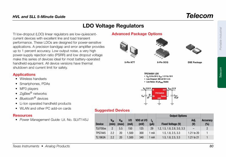
HVL and SLL 5-Minute Guide Telecom
Texas Instruments • Analog Products 80
Por
tab
le In
dus
tria
lTe
leco
m
TI low-dropout (LDO) linear regulators are low-quiescent- current devices with excellent line and load transient performance. These LDOs are designed for power-sensitive applications. A precision bandgap and error amplifier provides up to 1 percent accuracy. Low output noise, a very high power-supply rejection ratio (PSRR) and low dropout voltage make this series of devices ideal for most battery-operated handheld equipment. All device versions have thermal shutdown and current limit for safety.
Applications• Wireless handsets• Smartphones, PDAs• MP3 players• ZigBee® networks• Bluetooth® devices• Li-Ion operated handheld products• WLAN and other PC add-on cards
Resources• Power Management Guide: Lit. No. SLVT145J
LDO .Voltage .Regulators
Suggested .DevicesOutput Options
DeviceVIN
(min)VIN
(max)I/O
(mA)VDO at I/O
(mV)lq
(µA) Fixed Voltage (V)Adj. (V)
Accuracy (%)
TLV700xx 2 5.5 150 125 29 1.2, 1.5, 1.8, 2.8, 3.0, 3.3 – 2
TPS7A45 2.2 20 1,500 300 1 mA 1.5, 1.8, 2.5, 3.3 1.21 to 20 1
TL1963A 2.2 20 1,500 340 1 mA 1.5, 1.8, 2.5, 3.3 1.21 to 21 1
COUT10 µF
CIN
VIN 12.0 V VOUT 3.3 V
TPS7A4501 LDO• VIN 2.0 to 20 V, VOUT 1.2 V to 19 V• Low Dropout: 300 mV @ 1.5 A• Low Noise: 35 µVRMS Stable
ON
OFF
IN
EN
OUT
TPS7A4533
SenseGND
Advanced .Package .Options
5-Pin .KTT 6-Pin .DCQ DSE .Package
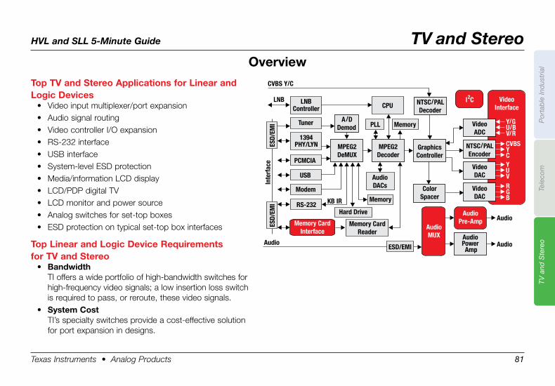
HVL and SLL 5-Minute Guide TV and Stereo
Texas Instruments • Analog Products 81
Por
tab
le In
dus
tria
lTe
leco
mTV
and
Ste
reo
Top .TV .and .Stereo .Applications .for .Linear .and .Logic .Devices
• Video input multiplexer/port expansion• Audio signal routing• Video controller I/O expansion• RS-232 interface• USB interface• System-level ESD protection• Media/information LCD display• LCD/PDP digital TV• LCD monitor and power source• Analog switches for set-top boxes• ESD protection on typical set-top box interfaces
Top .Linear .and .Logic .Device .Requirements . .for .TV .and .Stereo
• BandwidthTI offers a wide portfolio of high-bandwidth switches for high-frequency video signals; a low insertion loss switch is required to pass, or reroute, these video signals.
• System .CostTI’s specialty switches provide a cost-effective solution for port expansion in designs.
Overview
LNBController
Tuner
1394PHY/LYN
PCMCIA
ModemMemory
Memory
CPU
AudioDACs
GraphicsController
ColorSpacer
VideoDAC
VideoADC
NTSC/PALEncoder
NTSC/PALDecoder
VideoDAC
AudioPowerAmp
CVBS Y/C
LNB
Inte
rfac
e
KB IR
Audio
Audio
Audio
USB
RS-232Hard Drive
MPEG2DeMUX
MPEG2Decoder
A/DDemod PLL
VideoInterface
AudioPre-Amp
AudioMUX
B
V
C
V/R
G
U
Y
U/B
R
Y
CVBS
Y/G
Memory CardInterface
Memory CardReader
I C2
ESD/EMI
ESD/
EMI
ESD/
EMI
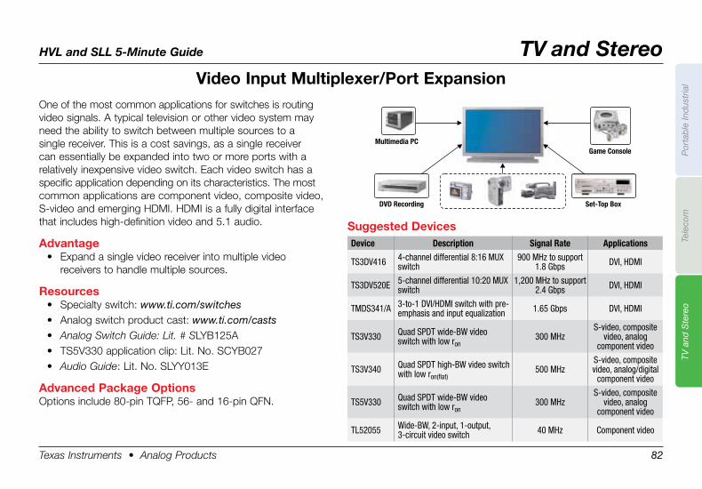
HVL and SLL 5-Minute Guide TV and Stereo
Texas Instruments • Analog Products 82
Por
tab
le In
dus
tria
lTe
leco
mTV
and
Ste
reo
Video .Input .Multiplexer/Port .Expansion
Suggested .DevicesDevice Description Signal Rate Applications
TS3DV416 4-channel differential 8:16 MUX switch
900 MHz to support 1.8 Gbps DVI, HDMI
TS3DV520E 5-channel differential 10:20 MUX switch
1,200 MHz to support 2.4 Gbps DVI, HDMI
TMDS341/A 3-to-1 DVI/HDMI switch with pre-emphasis and input equalization 1.65 Gbps DVI, HDMI
TS3V330 Quad SPDT wide-BW video switch with low ron
300 MHzS-video, composite
video, analog component video
TS3V340 Quad SPDT high-BW video switch with low ron(flat)
500 MHzS-video, composite video, analog/digital
component video
TS5V330 Quad SPDT wide-BW video switch with low ron
300 MHzS-video, composite
video, analog component video
TL52055 Wide-BW, 2-input, 1-output, 3-circuit video switch 40 MHz Component video
Multimedia PC
DVD Recording
Game Console
Set-Top Box
One of the most common applications for switches is routing video signals. A typical television or other video system may need the ability to switch between multiple sources to a single receiver. This is a cost savings, as a single receiver can essentially be expanded into two or more ports with a relatively inexpensive video switch. Each video switch has a specific application depending on its characteristics. The most common applications are component video, composite video, S-video and emerging HDMI. HDMI is a fully digital interface that includes high-definition video and 5.1 audio.
Advantage• Expand a single video receiver into multiple video
receivers to handle multiple sources.
Resources• Specialty switch: www.ti.com/switches• Analog switch product cast: www.ti.com/casts• Analog Switch Guide: Lit. # SLYB125A• TS5V330 application clip: Lit. No. SCYB027• Audio Guide: Lit. No. SLYY013E
Advanced .Package .OptionsOptions include 80-pin TQFP, 56- and 16-pin QFN.
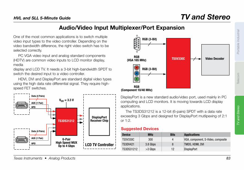
HVL and SLL 5-Minute Guide TV and Stereo
Texas Instruments • Analog Products 83
Por
tab
le In
dus
tria
lTe
leco
mTV
and
Ste
reo
Audio/Video .Input .Multiplexer/Port .ExpansionOne of the most common applications is to switch multiple video input types to the video controller. Depending on the video bandwidth difference, the right video switch has to be selected correctly.
PC VGA video input and analog standard components (HDTV) are common video inputs to LCD monitor display, media display and LCD TV. It needs a 3-bit high-bandwidth SPDT to switch the desired input to a video controller.
HDVI, DVI and DisplayPort are standard digital video types using the high data rate differential signal. They require high-speed FET switches.
Video DecoderTS5V330C
RGB (3-Bit)
RGB(VGA 165 MHz)
RGB (3-Bit)
RGB(Component 10/40 MHz)
TS3DS31212DisplayPort
Receiver Chip
LCD TV Controller6-Pair
High Speed MUXUp to 4 Gbps
VDD = 3.3 VData (4 Pairs)
AUX (1 Pair)
HPD
Data (4 Pairs)
AUX (1 Pair)
HPD
DisplayPort is a new standard audio/video port, used mainly in PC computing and LCD monitors. It is moving towards LCD display applications.
The TS3DS31212 is a 12-bit (6-pairs) SPDT with a data rate exceeding 3 Gbps and designed for DisplayPort mutlipexing of 2:1 or 1:2.
Suggested .DevicesDevice MHz Bits ApplicationsTS5V330C 300 4 VGA, component, S-Video, composite
TS3DV421 3.8 Gbps 8 TMDS, HDMI, DVI
TS3DS31212 >3 Gbps 12 DisplayPort
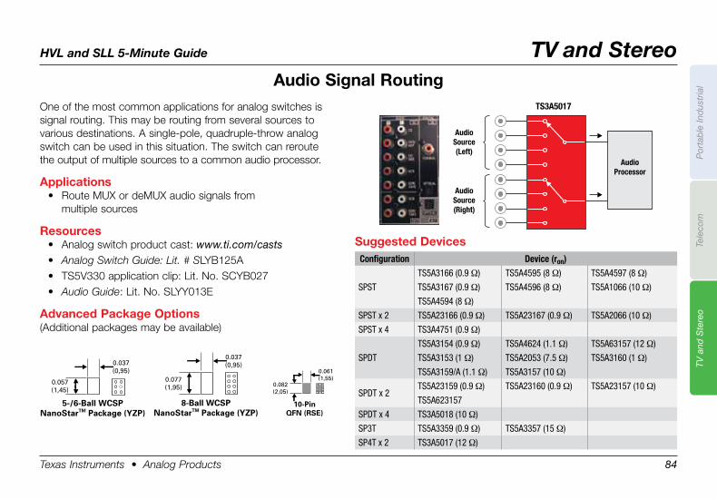
HVL and SLL 5-Minute Guide TV and Stereo
Texas Instruments • Analog Products 84
Por
tab
le In
dus
tria
lTe
leco
mTV
and
Ste
reo
One of the most common applications for analog switches is signal routing. This may be routing from several sources to various destinations. A single-pole, quadruple-throw analog switch can be used in this situation. The switch can reroute the output of multiple sources to a common audio processor.
Applications• Route MUX or deMUX audio signals from
multiple sources
Resources• Analog switch product cast: www.ti.com/casts• Analog Switch Guide: Lit. # SLYB125A• TS5V330 application clip: Lit. No. SCYB027• Audio Guide: Lit. No. SLYY013E
Advanced .Package .Options(Additional packages may be available)
Suggested .DevicesConfiguration Device (ron)
SPST
TS5A3166 (0.9 Ω) TS5A4595 (8 Ω) TS5A4597 (8 Ω)
TS5A3167 (0.9 Ω) TS5A4596 (8 Ω) TS5A1066 (10 Ω)
TS5A4594 (8 Ω)
SPST x 2 TS5A23166 (0.9 Ω) TS5A23167 (0.9 Ω) TS5A2066 (10 Ω)
SPST x 4 TS3A4751 (0.9 Ω)
SPDT
TS5A3154 (0.9 Ω) TS5A4624 (1.1 Ω) TS5A63157 (12 Ω)
TS5A3153 (1 Ω) TS5A2053 (7.5 Ω) TS5A3160 (1 Ω)
TS5A3159/A (1.1 Ω) TS5A3157 (10 Ω)
SPDT x 2TS5A23159 (0.9 Ω) TS5A23160 (0.9 Ω) TS5A23157 (10 Ω)
TS5A623157
SPDT x 4 TS3A5018 (10 Ω)
SP3T TS5A3359 (0.9 Ω) TS5A3357 (15 Ω)
SP4T x 2 TS3A5017 (12 Ω)
Audio
Source
(Left)
Audio
Processor
TS3A5017
Audio
Source
(Right)
Audio .Signal .Routing
0.037(0,95)
0.057(1,45)
5-/6-Ball WCSPNanoStarTM Package (YZP)
0.037(0,95)
0.077(1,95)
8-Ball WCSPNanoStarTM Package (YZP)
0.061(1,55)
0.082(2,05)
10-PinQFN (RSE)
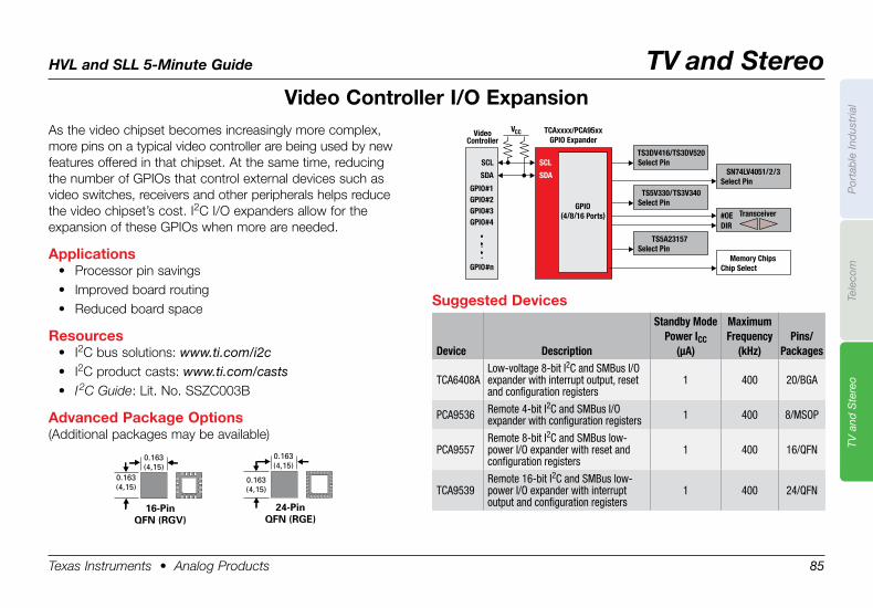
HVL and SLL 5-Minute Guide TV and Stereo
Texas Instruments • Analog Products 85
Por
tab
le In
dus
tria
lTe
leco
mTV
and
Ste
reo
As the video chipset becomes increasingly more complex, more pins on a typical video controller are being used by new features offered in that chipset. At the same time, reducing the number of GPIOs that control external devices such as video switches, receivers and other peripherals helps reduce the video chipset’s cost. I2C I/O expanders allow for the expansion of these GPIOs when more are needed.
Applications• Processor pin savings• Improved board routing• Reduced board space
Resources• I2C bus solutions: www.ti.com/i2c• I2C product casts: www.ti.com/casts• I 2C Guide: Lit. No. SSZC003B
Advanced .Package .Options(Additional packages may be available)
Suggested .Devices
Device Description
Standby ModePower ICC
(µA)
MaximumFrequency
(kHz)Pins/
Packages
TCA6408ALow-voltage 8-bit I2C and SMBus I/O expander with interrupt output, reset and configuration registers
1 400 20/BGA
PCA9536 Remote 4-bit I2C and SMBus I/O expander with configuration registers 1 400 8/MSOP
PCA9557Remote 8-bit I2C and SMBus low-power I/O expander with reset and configuration registers
1 400 16/QFN
TCA9539Remote 16-bit I2C and SMBus low-power I/O expander with interrupt output and configuration registers
1 400 24/QFN
TS3DV416/TS3DV520Select Pin
SN74LV4051/2/3Select Pin
TS5V330/TS3V340Select Pin
#OEDIR
TS5A23157Select Pin
Memory ChipsChip Select
VideoController
TCAxxxx/PCA95xxGPIO Expander
VCC
SCL
SDA
GPIO#1GPIO#2GPIO#3GPIO#4
.
.
.GPIO#n
Transceiver
SCL
SDA
GPIO(4/8/16 Ports)
Video .Controller .I/O .Expansion
0.163(4,15)
0.163(4,15)
16-PinQFN (RGV)
0.163(4,15)
0.163(4,15)
24-PinQFN (RGE)
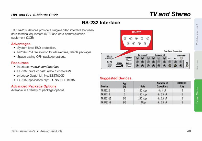
HVL and SLL 5-Minute Guide TV and Stereo
Texas Instruments • Analog Products 86
Por
tab
le In
dus
tria
lTe
leco
mTV
and
Ste
reo
RS-232 .InterfaceTIA/EIA-232 devices provide a single-ended interface between data terminal equipment (DTE) and data communication equipment (DCE).
Advantages• System-level ESD protection.• NiPdAu Pb-Free solution for whisker-free, reliable packages.• Space-saving QFN package options.
Resources• Interface: www.ti.com/interface• RS-232 product cast: www.ti.com/casts• Interface Guide: Lit. No. SSZT009D• RS-232 application clip: Lit. No. SLLB103A
Advanced .Package .OptionsAvailable in a variety of package options.
Suggested .Devices
DeviceVCC(V) Rate
Number ofCapacitors
HBM ESD(kV)
TRS232E 5 120 kbps 4 x 1 µF 15
TRS202E 5 120 kbps 4 x 0.1 µF 15
TRS3232E 3/5 250 kbps 4 x 0.1 µF 15
TRSF3232 3/5 1 Mbps 4 x 0.1 µF 15
TV
SubwooferRGB Out
Component 1 Component 2
AV1AV2
RS-232
RGB InDVI INRJ-45
Rear Panel Connection
RS-232
8
3
9
45
7
2
6
1
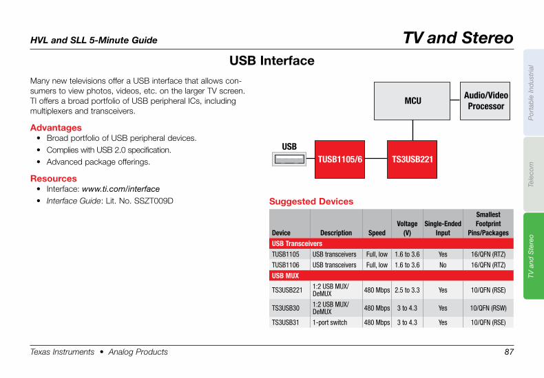
HVL and SLL 5-Minute Guide TV and Stereo
Texas Instruments • Analog Products 87
Por
tab
le In
dus
tria
lTe
leco
mTV
and
Ste
reo
USB .InterfaceMany new televisions offer a USB interface that allows con-sumers to view photos, videos, etc. on the larger TV screen. TI offers a broad portfolio of USB peripheral ICs, including multiplexers and transceivers.
Advantages• Broad portfolio of USB peripheral devices.• Complies with USB 2.0 specification.• Advanced package offerings.
Resources• Interface: www.ti.com/interface• Interface Guide: Lit. No. SSZT009D
TUSB1105/6
USB
MCU
TS3USB221
Audio/Video
Processor
Suggested .Devices
Device Description SpeedVoltage
(V)Single-Ended
Input
Smallest Footprint
Pins/PackagesUSB TransceiversTUSB1105 USB transceivers Full, low 1.6 to 3.6 Yes 16/QFN (RTZ)
TUSB1106 USB transceivers Full, low 1.6 to 3.6 No 16/QFN (RTZ)
USB MUX
TS3USB221 1:2 USB MUX/DeMUX 480 Mbps 2.5 to 3.3 Yes 10/QFN (RSE)
TS3USB30 1:2 USB MUX/DeMUX 480 Mbps 3 to 4.3 Yes 10/QFN (RSW)
TS3USB31 1-port switch 480 Mbps 3 to 4.3 Yes 10/QFN (RSE)
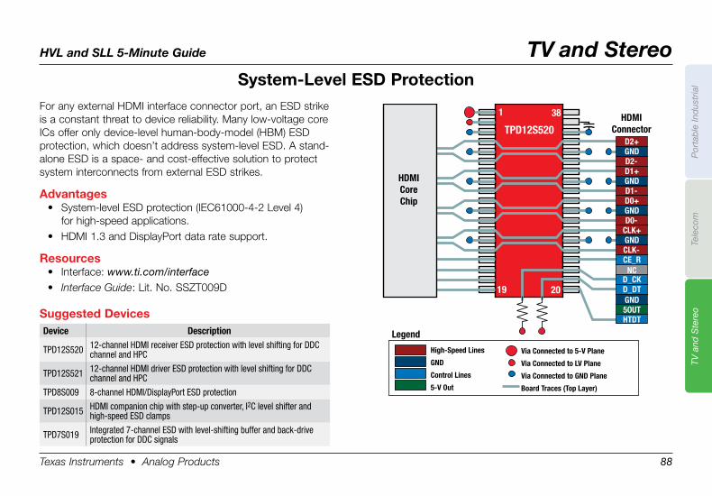
HVL and SLL 5-Minute Guide TV and Stereo
Texas Instruments • Analog Products 88
Por
tab
le In
dus
tria
lTe
leco
mTV
and
Ste
reo
System-Level .ESD .ProtectionFor any external HDMI interface connector port, an ESD strike is a constant threat to device reliability. Many low-voltage core ICs offer only device-level human-body-model (HBM) ESD protection, which doesn’t address system-level ESD. A stand-alone ESD is a space- and cost-effective solution to protect system interconnects from external ESD strikes.
Advantages• System-level ESD protection (IEC61000-4-2 Level 4)
for high-speed applications.• HDMI 1.3 and DisplayPort data rate support.
Resources• Interface: www.ti.com/interface• Interface Guide: Lit. No. SSZT009D
High-Speed Lines
GND
Control Lines
5-V Out
Via Connected to LV Plane
Via Connected to GND Plane
Board Traces (Top Layer)
Via Connected to 5-V Plane
TPD12S520HDMI
Connector
1 38
2019
HDMICoreChip
Legend
D2+GNDD2-D1+GNDD1-D0+GNDD0-
CLK+GNDCLK-CE_R
NCD_CKD_DTGND5OUTHTDTSuggested .Devices
Device Description
TPD12S520 12-channel HDMI receiver ESD protection with level shifting for DDC channel and HPC
TPD12S521 12-channel HDMI driver ESD protection with level shifting for DDC channel and HPC
TPD8S009 8-channel HDMI/DisplayPort ESD protection
TPD12S015 HDMI companion chip with step-up converter, I2C level shifter and high-speed ESD clamps
TPD7S019 Integrated 7-channel ESD with level-shifting buffer and back-driveprotection for DDC signals
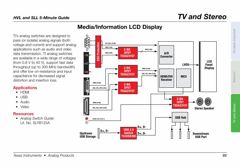
HVL and SLL 5-Minute Guide TV and Stereo
Texas Instruments • Analog Products 89
Por
tab
le In
dus
tria
lTe
leco
mTV
and
Ste
reo
Media/Information .LCD .DisplayTI’s analog switches are designed to pass (or isolate) analog signals (both voltage and current) and support analog applications such as audio and video data transmission. TI analog switches are available in a wide range of voltages (from 0.8 V to 40 V), support fast data throughput (up to 300-MHz bandwidth) and offer low on-resistance and input capacitance for decreased signal distortion and insertion loss.
Applications• HDMI• USB• Audio• Video
Resources• Analog Switch Guide:
Lit. No. SLYB125A
USB Hub
A/DConverter
HDMI/DVIReceiver
MCU
LVDS
Stereo Speaker
LCDPanel
Display
DownstreamUSB Port
2-Bit SPDT
TS5A23157
USB 2.0Switch
TS3USB39E
D+, D-
D+, D-D+, D-
UpstreamUSB Storage
Audio Line in (R, L)
DDC, CEC, HPD (4-Bit)
TMDS (8-Bit)
DDC, CEC, HPD (4-Bit)
TMDS (8-Bit)
RGB (3-Bit)
RGB (3-Bit)
H/V-Sync (3-Bit)
RGB (3-Bit)
DDC, CEC, HPD (4-Bit)
TMDS (8-Bit)
2-Bit SPDT
TS5A23157
2-Bit SPDT
TS5A23157
2-Bit SPDT
TS5A23157
ESD
Prot
ectio
n
?????????????????????Y
PbPt
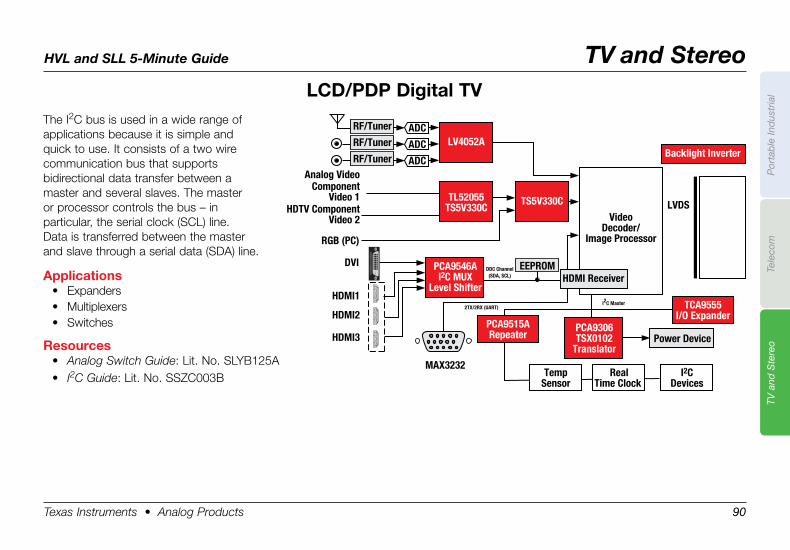
HVL and SLL 5-Minute Guide TV and Stereo
Texas Instruments • Analog Products 90
Por
tab
le In
dus
tria
lTe
leco
mTV
and
Ste
reo
LCD/PDP .Digital .TVThe I2C bus is used in a wide range of applications because it is simple and quick to use. It consists of a two wire communication bus that supports bidirectional data transfer between a master and several slaves. The master or processor controls the bus – in particular, the serial clock (SCL) line. Data is transferred between the master and slave through a serial data (SDA) line.
Applications• Expanders• Multiplexers• Switches
Resources• Analog Switch Guide: Lit. No. SLYB125A• I2C Guide: Lit. No. SSZC003B
VideoDecoder/
Image Processor
I2CDevices
LVDS
TCA9555I/O Expander
PCA9515ARepeater
HDMI Receiver
Backlight Inverter
Power Device
RealTime Clock
TempSensor
LV4052A
TL52055TS5V330C
TS5V330C
PCA9546AI2C MUX
Level ShifterHDMI1
DVI
RGB (PC)
ComponentVideo 1
Analog Video
HDTV ComponentVideo 2
HDMI2
HDMI3
DDC Channel(SDA, SCL)
2TX/2RX (UART)I2C Master
EEPROM
MAX323219
17
15
13
11
97
53
18
16
14
12
10
86
42
119
17
15
13
11
97
53
18
16
14
12
10
86
42
119
17
15
13
11
97
53
18
16
14
12
10
86
42
1
ADCRF/Tuner
ADCRF/Tuner
ADCRF/Tuner
PCA9306TSX0102
Translator
?????????????????????
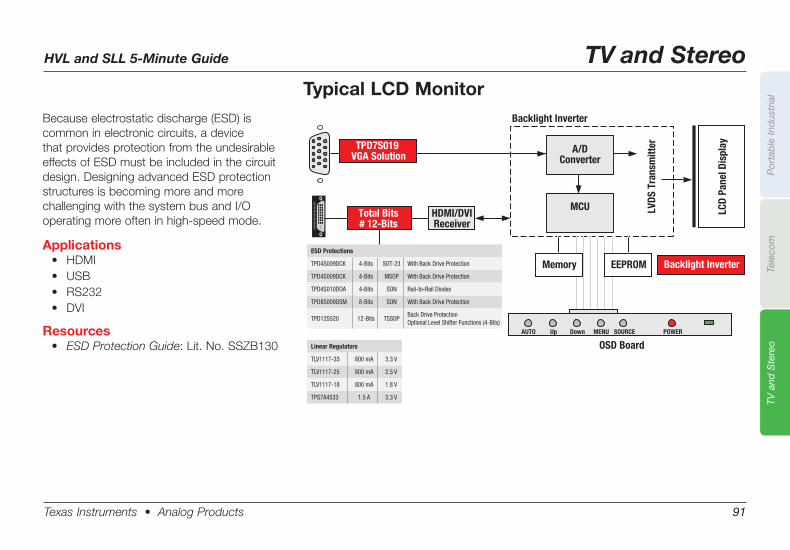
HVL and SLL 5-Minute Guide TV and Stereo
Texas Instruments • Analog Products 91
Por
tab
le In
dus
tria
lTe
leco
mTV
and
Ste
reo
A/DConverter
MCU LCD
Pane
l Dis
play
LVDS
Tra
nsm
itter
AUTO Up Down MENU SOURCE POWER
Backlight Inverter
Backlight Inverter
OSD Board
Memory EEPROM
?????????????????????
HDMI/DVIReceiver
Total Bits# 12-Bits
TPD7S019 VGA Solution
Typical LCD MonitorBecause electrostatic discharge (ESD) is common in electronic circuits, a device that provides protection from the undesirable effects of ESD must be included in the circuit design. Designing advanced ESD protection structures is becoming more and more challenging with the system bus and I/O operating more often in high-speed mode.
Applications• HDMI• USB• RS232• DVI
Resources• ESD Protection Guide:Lit.No.SSZB130
ESD Protections
TPD4S009DCK 4-Bits SOT-23 With Back Drive Protection
TPD4S009DCK 4-Bits MSOP With Back Drive Protection
TPD4S010DOA 4-Bits SON Rail-to-Rail Diodes
TPD8S009DSM 8-Bits SON With Back Drive Protection
TPD12S520 12-Bits TSSOPBack Drive Protection Optional Level Shifter Functions (4-Bits)
Linear Regulators
TLV1117-33 800 mA 3.3 V
TLV1117-25 800 mA 2.5 V
TLV1117-18 800 mA 1.8 V
TPS7A4533 1.5 A 3.3 V
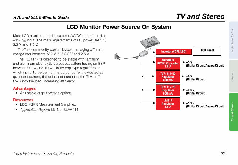
HVL and SLL 5-Minute Guide TV and Stereo
Texas Instruments • Analog Products 92
Por
tab
le In
dus
tria
lTe
leco
mTV
and
Ste
reo
LCD .Monitor .Power .Source .On .SystemMost LCD monitors use the external AC/DC adapter and a +12-VDC input. The main requirements of DC power are 5 V, 3.3 V and 2.5 V.
TI offers commodity power devices managing different voltage requirements of 9 V, 5 V, 3.3 V and 2.5 V.
The TLV1117 is designed to be stable with tantalum and aluminum electrolytic output capacitors having an ESR between 0.2 Ω and 10 Ω. Unlike pnp-type regulators, in which up to 10 percent of the output current is wasted as quiescent current, the quiescent current of the TLV1117 flows into the load, increasing efficiency.
Advantages• Adjustable-output voltage options
Resources• LDO PSRR Measurement Simplified• Application Report: Lit. No. SLAA414
MC34063DC/DC Converter
1.5 A
TLV1117-50Regulator800 mA
TLV1117-25Regulator800 mA
LM317Regulator
1.5 A
Inverter (CCFL/LED) LCD Panel
+5 V (Digital Circuit/Analog Circuit)
+5 V (Digital Circuit)
+2.5 V (Digital Circuit)
+3.3 V (Digital Circuit/Analog Circuit)
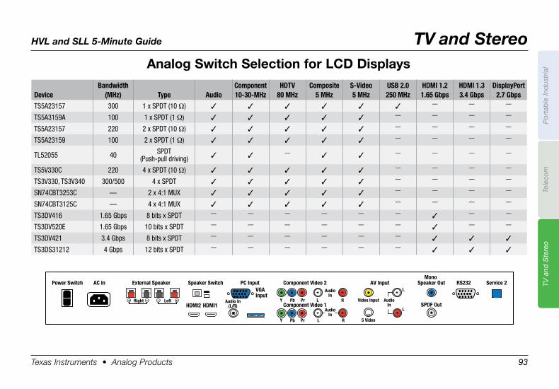
HVL and SLL 5-Minute Guide TV and Stereo
Texas Instruments • Analog Products 93
Por
tab
le In
dus
tria
lTe
leco
mTV
and
Ste
reo
Analog .Switch .Selection .for .LCD .Displays
DeviceBandwidth
(MHz) Type AudioComponent 10-30-MHz
HDTV80 MHz
Composite5 MHz
S-Video5 MHz
USB 2.0250 MHz
HDMI 1.21.65 Gbps
HDMI 1.33.4 Gbps
DisplayPort2.7 Gbps
TS5A23157 300 1 x SPDT (10 Ω) 3 3 3 3 3 3 — — —
TS5A3159A 100 1 x SPDT (1 Ω) 3 3 3 3 3 — — — —
TS5A23157 220 2 x SPDT (10 Ω) 3 3 3 3 3 — — — —
TS5A23159 100 2 x SPDT (1 Ω) 3 3 3 3 3 — — — —
TL52055 40 SPDT (Push-pull driving) 3 3 — 3 3 — — — —
TS5V330C 220 4 x SPDT (10 Ω) 3 3 3 3 3 — — — —
TS3V330, TS3V340 300/500 4 x SPDT 3 3 3 3 3 — — — —
SN74CBT3253C — 2 x 4:1 MUX 3 3 3 3 3 — — — —
SN74CBT3125C — 4 x 4:1 MUX 3 3 3 3 3 — — — —
TS3DV416 1.65 Gbps 8 bits x SPDT — — — — — — 3 — —
TS3DV520E 1.65 Gbps 10 bits x SPDT — — — — — — 3 — —
TS3DV421 3.4 Gbps 8 bits x SPDT — — — — — — 3 3 3
TS3DS31212 4 Gbps 12 bits x SPDT — — — — — — 3 3 3
AC In External Speaker Speaker Switch PC Input Component Video 2 AV InputMono
Speaker Out
SPDF Out
RS232 Service 2
Component Video 1
VGA Input
HDMI2 HDMI1Audio In
(L/R)Y Pb Pr R Video Input Audio
In
5 VideoY Pb Pr R
L
L
L
AudioIn
AudioIn
L
Right
Power Switch
+ +
+
+
+ +
+ – Left +–
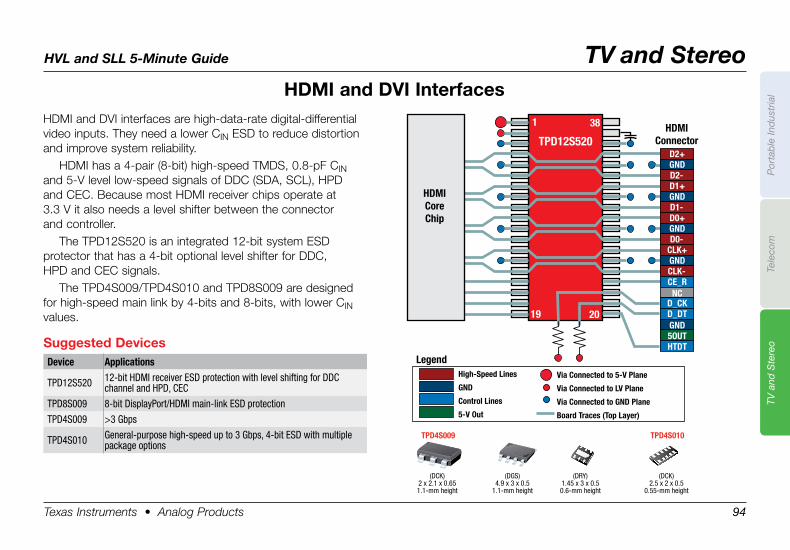
HVL and SLL 5-Minute Guide TV and Stereo
Texas Instruments • Analog Products 94
Por
tab
le In
dus
tria
lTe
leco
mTV
and
Ste
reo
HDMI .and .DVI .InterfacesHDMI and DVI interfaces are high-data-rate digital-differential video inputs. They need a lower CIN ESD to reduce distortion and improve system reliability.
HDMI has a 4-pair (8-bit) high-speed TMDS, 0.8-pF CIN and 5-V level low-speed signals of DDC (SDA, SCL), HPD and CEC. Because most HDMI receiver chips operate at 3.3 V it also needs a level shifter between the connector and controller.
The TPD12S520 is an integrated 12-bit system ESD protector that has a 4-bit optional level shifter for DDC, HPD and CEC signals.
The TPD4S009/TPD4S010 and TPD8S009 are designed for high-speed main link by 4-bits and 8-bits, with lower CIN values.
Suggested .DevicesDevice Applications
TPD12S520 12-bit HDMI receiver ESD protection with level shifting for DDC channel and HPD, CEC
TPD8S009 8-bit DisplayPort/HDMI main-link ESD protection
TPD4S009 >3 Gbps
TPD4S010 General-purpose high-speed up to 3 Gbps, 4-bit ESD with multiple package options
High-Speed Lines
GND
Control Lines
5-V Out
Via Connected to LV Plane
Via Connected to GND Plane
Board Traces (Top Layer)
Via Connected to 5-V Plane
TPD12S520HDMI
Connector
1 38
2019
HDMICoreChip
Legend
D2+GNDD2-D1+GNDD1-D0+GNDD0-
CLK+GNDCLK-CE_R
NCD_CKD_DTGND5OUTHTDT
TPD4S009
(DCK)2 x 2.1 x 0.651.1-mm height
(DGS)4.9 x 3 x 0.5
1.1-mm height
(DRY)1.45 x 3 x 0.50.6-mm height
TPD4S010
(DCK)2.5 x 2 x 0.5
0.55-mm height
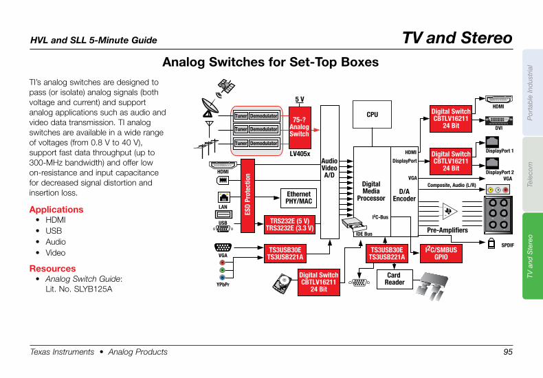
HVL and SLL 5-Minute Guide TV and Stereo
Texas Instruments • Analog Products 95
Por
tab
le In
dus
tria
lTe
leco
mTV
and
Ste
reo
Analog .Switches .for .Set-Top .BoxesTI’s analog switches are designed to pass (or isolate) analog signals (both voltage and current) and support analog applications such as audio and video data transmission. TI analog switches are available in a wide range of voltages (from 0.8 V to 40 V), support fast data throughput (up to 300-MHz bandwidth) and offer low on-resistance and input capacitance for decreased signal distortion and insertion loss.
Applications• HDMI• USB• Audio• Video
Resources• Analog Switch Guide:
Lit. No. SLYB125A
EthernetPHY/MAC
Card Reader
Digital SwitchCBTLV16211
24 Bit
DVI
DisplayPort 1
DisplayPort 2
DisplayPort
VGA
HDMI
VGA
SPDIF
??
??
??
??
??
??
Pre-Amplifiers
DigitalMedia
ProcessorD/A
Encoder
?????????????????????
19 17 15 13 11 9 7 5 318 16 14 12 10 8 6 4 2
1
HDMI
19 17 15 13 11 9 7 5 318 16 14 12 10 8 6 4 2
1
LAN
I2C-Bus
Composite, Audio (L/R)
USB
VGA
YPbPr
HDMI
Tuner Demodulator
Tuner Demodulator
Tuner Demodulator
TS3USB30ETS3USB221A
TS3USB30ETS3USB221A
TRS232E (5 V)TRS3232E (3.3 V)
75-?AnalogSwitch
I2C/SMBUSGPIO
ESD
Prot
ectio
n
IDE Bus
AudioVideoA/D
5 V
LV405x
CPU Digital SwitchCBTLV16211
24 Bit
Digital SwitchCBTLV16211
24 Bit
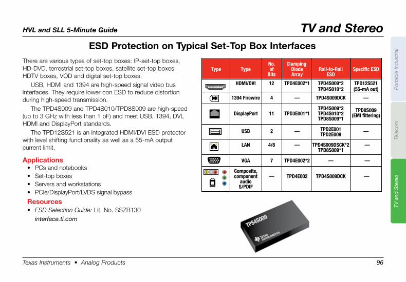
HVL and SLL 5-Minute Guide TV and Stereo
Texas Instruments • Analog Products 96
Por
tab
le In
dus
tria
lTe
leco
mTV
and
Ste
reo
ESD .Protection .on .Typical .Set-Top .Box .InterfacesThere are various types of set-top boxes: IP-set-top boxes, HD-DVD, terrestrial set-top boxes, satellite set-top boxes, HDTV boxes, VOD and digital set-top boxes.
USB, HDMI and 1394 are high-speed signal video bus interfaces. They require lower con ESD to reduce distortion during high-speed transmission.
The TPD4S009 and TPD4S010/TPD8S009 are high-speed (up to 3 GHz with less than 1 pF) and meet USB, 1394, DVI, HDMI and DisplayPort standards.
The TPD12S521 is an integrated HDMI/DVI ESD protector with level shifting functionality as well as a 55-mA output current limit.
Applications• PCs and notebooks• Set-top boxes• Servers and workstations• PCIe/DisplayPort/LVDS signal bypass
Resources• ESD Selection Guide: Lit. No. SSZB130 interface.ti.com
No. Clamping Type Type of Diode Rail-to-Rail Specific ESD Bits Array ESD
HDMI/DVI 12 TPD4E002*1 TPD4S009*2 TPD12S521 TPD4S010*2 (55-mA out) 1394 Firewire 4 — TPD4S009DCK —
DisplayPort 11 TPD3E001*1
TPD4S009*2 TPD8S009 TPD4S010*2 (EMI filtering) TPD8S009*1
USB 2 — TPD2E001 — TPD2E009
LAN 4/8 — TPD4S009DSCK*2 — TPD8S009*1
VGA 7 TPD4E002*2 — —
Composite, — TPD4E002 TPD4S009DCK — component
audio S/PDIF
19 17 15 13 11 9 7 5 318 16 14 12 10 8 6 4 2
1
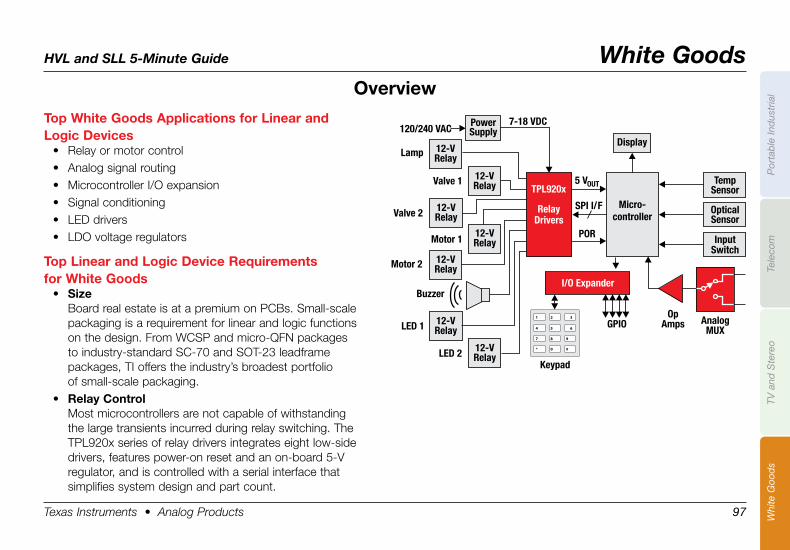
HVL and SLL 5-Minute Guide White Goods
Texas Instruments • Analog Products 97
Por
tab
le In
dus
tria
lTe
leco
mTV
and
Ste
reo
Whi
te G
ood
s
Top .White .Goods .Applications .for .Linear .and .Logic .Devices
• Relay or motor control• Analog signal routing• Microcontroller I/O expansion• Signal conditioning• LED drivers• LDO voltage regulators
Top .Linear .and .Logic .Device .Requirements . .for .White .Goods
• SizeBoard real estate is at a premium on PCBs. Small-scale packaging is a requirement for linear and logic functions on the design. From WCSP and micro-QFN packages to industry-standard SC-70 and SOT-23 leadframe packages, TI offers the industry’s broadest portfolio of small-scale packaging.
• Relay .ControlMost microcontrollers are not capable of withstanding the large transients incurred during relay switching. The TPL920x series of relay drivers integrates eight low-side drivers, features power-on reset and an on-board 5-V regulator, and is controlled with a serial interface that simplifies system design and part count.
120/240 VAC7-18 VDC
Lamp
Valve 1
Valve 2
Motor 1
Motor 2
Buzzer
LED 1
LED 2
5 VOUT
Micro-controller
SPI I/F
POR
12-VRelay
12-VRelay Temp
Sensor
PowerSupply
Display
I/O Expander
OpticalSensor
InputSwitch
AnalogMUX
OpAmpsGPIO
Keypad
12-VRelay
12-VRelay
12-VRelay
12-VRelay
12-VRelay
TPL920x
RelayDrivers
Overview
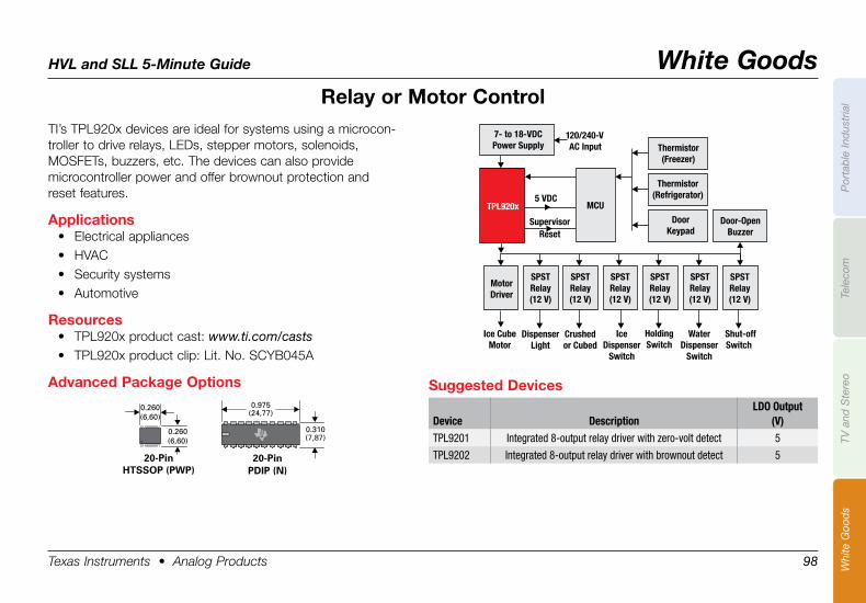
HVL and SLL 5-Minute Guide White Goods
Texas Instruments • Analog Products 98
Por
tab
le In
dus
tria
lTe
leco
mTV
and
Ste
reo
Whi
te G
ood
s
Relay .or .Motor .ControlTI’s TPL920x devices are ideal for systems using a microcon-troller to drive relays, LEDs, stepper motors, solenoids, MOSFETs, buzzers, etc. The devices can also provide microcontroller power and offer brownout protection and reset features.
Applications• Electrical appliances• HVAC• Security systems• Automotive
Resources• TPL920x product cast: www.ti.com/casts• TPL920x product clip: Lit. No. SCYB045A
Advanced .Package .Options
Thermistor(Freezer)
Thermistor(Refrigerator)
DoorKeypad
MotorDriver
Ice CubeMotor
DispenserLight
Crushedor Cubed
IceDispenser
Switch
WaterDispenser
Switch
HoldingSwitch
Shut-offSwitch
SPSTRelay(12 V)
SPSTRelay(12 V)
SPSTRelay(12 V)
SPSTRelay(12 V)
SPSTRelay(12 V)
SPSTRelay(12 V)
Door-OpenBuzzer
5 VDC
SupervisorReset
TPL920x
120/240-VAC Input
7- to 18-VDCPower Supply
MCU
0.260(6,60)
0.260(6,60)
20-PinHTSSOP (PWP)
0.975(24,77)
0.310(7,87)
20-Pin PDIP (N)
Suggested .Devices
Device DescriptionLDO Output
(V)TPL9201 Integrated 8-output relay driver with zero-volt detect 5
TPL9202 Integrated 8-output relay driver with brownout detect 5
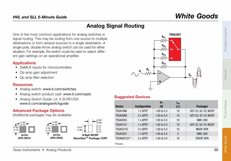
HVL and SLL 5-Minute Guide White Goods
Texas Instruments • Analog Products 99
Por
tab
le In
dus
tria
lTe
leco
mTV
and
Ste
reo
Whi
te G
ood
s
Analog .Signal .RoutingOne of the most common applications for analog switches is signal routing. This may be routing from one source to multiple destinations or from several sources to a single destination. A single-pole, double-throw analog switch can be used for either situation. For example, the switch could be used to select differ-ent gain settings on an operational amplifier.
Applications• DeMUX inputs for microcontrollers• Op amp gain adjustment• Op amp filter selection
Resources• Analog switch: www.ti.com/switches• Analog switch product cast: www.ti.com/casts• Analog Switch Guide: Lit. # SLYB125A
www.ti.com/analogswitchguide
Advanced .Package .Options(Additional packages may be available)
VIVO
TS5A3357
RG
RF4
RF3
RF2
RF1
+
–
Suggested .Devices
Device ConfigurationV+(V)
ron(Ω) Packages
TS5A1066 1 x SPST 1.65 to 5.5 10 SOT-23, SC-70, WCSP
TS5A2066 2 x SPST 1.65 to 5.5 10 SOT-23, SC-70, WCSP
TS5A2053 1 x SPDT 1.65 to 5.5 10 SM8, US8
TS5A3157 1 x SPDT 1.65 to 5.5 10 SOT-23, SC-70, WCSP
TS5A23157 2 x SPDT 1.65 to 5.5 10 MSOP, QFN
TS5A3357 1 x SP3T 1.65 to 5.5 5 SM8, US8
TS5A623157* 2 x SPDT 1.65 to 5.5 10 VSSOP, QFN
*Preview
0.037(0,95)
0.077(1,95)
8-Ball WCSPNanoStarTM Package (YZP)
0.163(4,15)
0.163(4,15)
16-PinQFN (RGV)
0.163(4,15)
0.163(4,15)
24-PinQFN (RGE)
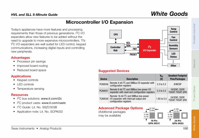
HVL and SLL 5-Minute Guide White Goods
Texas Instruments • Analog Products 100
Por
tab
le In
dus
tria
lTe
leco
mTV
and
Ste
reo
Whi
te G
ood
s
Microcontroller .I/O .ExpansionToday’s appliances have more features and processing requirements than those of previous generations. I2C I/O expanders allow new features to be added without the need to upgrade to more expensive microcontrollers. TI’s I2C I/O expanders are well suited for LED control, keypad communications, increasing digital inputs and control ling new peripherals.
Advantages• Processor pin savings• Improved board routing• Reduced board space
Applications• Keypad controls• LED controls• Temperature sensing
Resources• I2C bus solutions: www.ti.com/i2c• I2C product casts: www.ti.com/casts• I 2C Guide: Lit. No. SSZC003B• Application note: Lit. No. SCPA032
/INT
/RESET
SCL
SDA
Temp
Control
Controller
Hub
CPU
Fan
Control
Humidity
Sensors
LED
Status
Other
I C
I/O Expander
2
Advanced .Package .Options(Additional packages may be available)
0.144(3,65)
0.163(4,15)
16-PinQFN (RGY)
0.163(4,15)
0.163(4,15)
24-PinQFN (RGE)
Suggested .Devices
Device DescriptionVCC(V)
Smallest FootprintPins/Packages
PCA9536 Remote 4-bit I2C and SMBus I/O expander with configuration registers 2.3 to 5.5 8/WCSP
PCA9557 Remote 8-bit I2C and SMBus low-power I/O expander with reset and configuration registers 2.3 to 5.5 16/SOIC, SSOP,
TSSOP, TVSOP, QFN
TCA9539Remote 16-bit I2C and SMBus low-power I/O expander with interrupt output and configuration registers
1.65 to 5.5 24/SOIC, SSOP, TSSOP, TVSOP, QFN
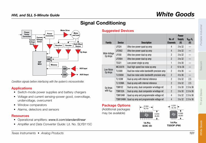
HVL and SLL 5-Minute Guide White Goods
Texas Instruments • Analog Products 101
Por
tab
le In
dus
tria
lTe
leco
mTV
and
Ste
reo
Whi
te G
ood
s
Signal .Conditioning
0.344(8,75)
0.244(6,20)
14-Pin SOIC (D)
0.201(5,10)
0.260(6,60)
14-Pin TSSOP (PW)
Applications• Switch-mode power supplies and battery chargers• Voltage and current sensing–power good, overvoltage,
undervoltage, overcurrent• Window comparators• Alarms, detectors and sensors
Resources• Operational amplifiers: www.ti.com/standardlinear• Amplifier and Data Converter Guide: Lit. No. SLYB115C
PowerFactor
Correction
CurrentVoltageSense
CurrentVoltageSense
Motor DriveMotor
and Load
DSPMCU
ADC
ADC
DAC
AUX Input
AUX Output
Op Amps
PowerConverter
Memory
Hall-EffectSensorResolver Encoder
Package .Options(Additional packages may be available)
Suggested .Devices
Family Device DescriptionNo. of
Channels
PowerSupply
(V)VREF VZ
(V)
Wide-VoltageOp Amps
LP324 Ultra-low-power quad op amp 4 3 to 32 —
LP2902 Ultra-low-power quad op amp 4 3 to 32 —
LP358 Ultra-low-power dual op amp 2 3 to 32 —
LP2904 Ultra-low-power dual op amp 2 3 to 32 —
TS321 Low-power single op amp 1 3 to 30 —
Low-NoiseOp Amps
MC33078 Dual high-speed low-noise op amp 2 10 to 36 —
TL5580 Dual low-noise wide-bandwidth precision amp 2 4 to 36 —
TL5580A Dual low-noise wide-bandwidth precision amp 2 4 to 36 —
Op Ampswith VREF
TL103W Dual op amp with internal reference 2 3 to 32 2.5
TL103WA Dual op amp with internal reference 2 3 to 32 2.5
TSM102 Dual op amp, dual comparator w/voltage ref. 2 3 to 30 2.5 to 36
TSM102A Dual op amp, dual comparator w/voltage ref. 2 3 to 30 2.5 to 36
TSM104W Quad op amp and programmable voltage ref. 4 3 to 32 2.5 to 36
TSM104WA Quad op amp and programmable voltage ref. 4 3 to 32 2.5 to 36
Condition signals before interfacing with the system’s microcontroller.
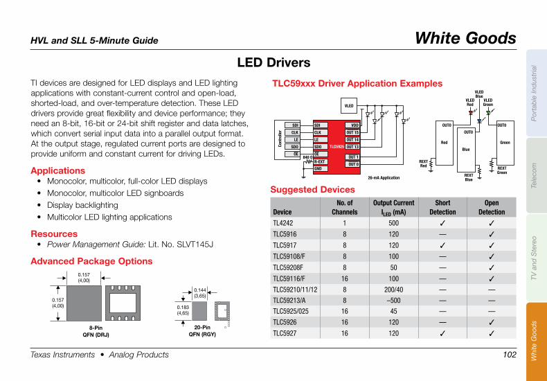
HVL and SLL 5-Minute Guide White Goods
Texas Instruments • Analog Products 102
Por
tab
le In
dus
tria
lTe
leco
mTV
and
Ste
reo
Whi
te G
ood
s
TI devices are designed for LED displays and LED lighting applications with constant-current control and open-load, shorted-load, and over-temperature detection. These LED drivers provide great flexibility and device performance; they need an 8-bit, 16-bit or 24-bit shift register and data latches, which convert serial input data into a parallel output format. At the output stage, regulated current ports are designed to provide uniform and constant current for driving LEDs.
Applications• Monocolor, multicolor, full-color LED displays• Monocolor, multicolor LED signboards• Display backlighting• Multicolor LED lighting applications
Resources• Power Management Guide: Lit. No. SLVT145J
Advanced .Package .Options
LED .Drivers
0.157 (4,00)
0.157 (4,00)
8-PinQFN .(DRJ)
0.144 (3,65)
0.183 (4,65)
20-PinQFN .(RGY) .
SDI
VLED
26-mA Application
Red
REXTRed
VLEDRed
VLEDGreen
VLEDBlue
REXTBlue
REXTGreen
OUT0
TLC5925
CLK
LE
SDO
VDD
OUT 15
OUT 14
OUT 13
OUT 1
OUT 0R-EXT
GND
840 OOE
Cont
rolle
r
SDI
CLK
LE
SDO
OE
Green
OUT0
Blue
OUT0
TLC59xxx .Driver .Application .Examples
Suggested .Devices
DeviceNo. of
ChannelsOutput Current
ILED (mA)Short
DetectionOpen
Detection
TL4242 1 500 3 3
TLC5916 8 120 — 3
TLC5917 8 120 3 3
TLC59108/F 8 100 — 3
TLC59208F 8 50 — 3
TLC59116/F 16 100 — 3
TLC59210/11/12 8 200/40 — —
TLC59213/A 8 –500 — —
TLC5925/025 16 45 — —
TLC5926 16 120 — 3
TLC5927 16 120 3 3
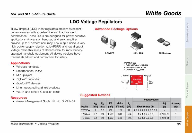
HVL and SLL 5-Minute Guide White Goods
Texas Instruments • Analog Products 103
Por
tab
le In
dus
tria
lTe
leco
mTV
and
Ste
reo
Whi
te G
ood
s
TI low-dropout (LDO) linear regulators are low-quiescent- current devices with excellent line and load transient performance. These LDOs are designed for power-sensitive applications. A precision bandgap and error amplifier provide up to 1 percent accuracy. Low output noise, a very high power-supply rejection ratio (PSRR) and low dropout voltage make this series of devices ideal for most battery-operated handheld equipment. All device versions have thermal shutdown and current limit for safety.
Applications• Wireless handsets• Smartphones, PDAs• MP3 players• ZigBee® networks• Bluetooth® devices• Li-Ion operated handheld products• WLAN and other PC add-on cards
Resources• Power Management Guide: Lit. No. SLVT145J
LDO .Voltage .Regulators
Suggested .DevicesOutput Options
DeviceVIN
(min)VIN
(max)I/O
(mA)VDO at
I/O (mV)lq
(µA) Fixed Voltage (V)Adj. (V)
Accuracy (%)
TLV700xx 2 5.5 150 125 29 1.2, 1.5, 1.8, 2.8, 3.0, 3.3 – 2
TPS7A45 2.2 20 1,500 300 1 mA 1.5, 1.8, 2.5, 3.3 1.21 to 20 1
TL1963A 2.2 20 1,500 340 1 mA 1.5, 1.8, 2.5, 3.3 1.21 to 21 1
COUT10 µF
CIN
VIN 12.0 V VOUT 3.3 V
TPS7A4501 LDO• VIN 2.0 to 20 V, VOUT 1.2 V to 19 V• Low Dropout: 300 mV @ 1.5 A• Low Noise: 35 µVRMS Stable
ON
OFF
IN
EN
OUT
TPS7A4533
SenseGND
Advanced .Package .Options
5-Pin .KTT 6-Pin .DCQ DSE .Package
TI Worldwide Technical SupportInternetTI Semiconductor Product Information Center Home Pagesupport.ti.comTI E2E™ Community Home Pagee2e.ti.com
Product Information CentersAmericas Phone +1(972)644-5580
Brazil Phone 0800-891-2616
Mexico Phone 0800-670-7544
Fax +1(972)927-6377 Internet/Email support.ti.com/sc/pic/americas.htm
Europe, Middle East, and AfricaPhone
EuropeanFreeCall 00800-ASK-TEXAS (0080027583927)
International +49(0)8161802121
RussianSupport +7(4)959810701
Note:TheEuropeanFreeCall(TollFree)numberisnotactiveinallcountries.Ifyouhavetechnicaldifficultycallingthefreecallnumber,pleaseusetheinternationalnumberabove.
Fax +(49)(0)8161802045Internet support.ti.com/sc/pic/euro.htm
JapanPhone Domestic 0120-92-3326Fax International +81-3-3344-5317 Domestic 0120-81-0036Internet/Email International support.ti.com/sc/pic/japan.htm Domestic www.tij.co.jp/pic
AsiaPhone International +91-80-41381665 Domestic Toll-FreeNumber Australia 1-800-999-084 China 800-820-8682 HongKong 800-96-5941 India 1-800-425-7888 Indonesia 001-803-8861-1006 Korea 080-551-2804 Malaysia 1-800-80-3973 NewZealand 0800-446-934 Philippines 1-800-765-7404 Singapore 800-886-1028 Taiwan 0800-006800 Thailand 001-800-886-0010Fax +886-2-2378-6808Email [email protected]
[email protected] support.ti.com/sc/pic/asia.htm
B042210
Important Notice:TheproductsandservicesofTexasInstrumentsIncorporatedanditssubsidiariesdescribedhereinaresoldsubjecttoTI’sstandardtermsandconditionsofsale.CustomersareadvisedtoobtainthemostcurrentandcompleteinformationaboutTIproductsandservicesbeforeplacingorders.TIassumesnoliabilityforapplicationsassistance,customer’sapplicationsorproductdesigns,softwareperformance,orinfringementofpatents.Thepublicationofinformationregardinganyothercompany’sproductsorservicesdoesnotconstituteTI’sapproval,warrantyorendorsementthereof.
©2010TexasInstrumentsIncorporatedPrintedinU.S.A.by(Printer,City,State)
TheE2ECommunity,FlatLink,NanoStar,platformbarandWiLinkaretrademarksofTexasInstruments.TheBluetoothwordmarkandlogosareownedbyBluetoothSIG,Inc.Allothertrademarksarethepropertyoftheirrespectiveowners.
XX%
Cert no. XXX-XXX-000FOR POSITION ONLY
Required ClearanceSLYB128B
IMPORTANT NOTICE
Texas Instruments Incorporated and its subsidiaries (TI) reserve the right to make corrections, modifications, enhancements, improvements,and other changes to its products and services at any time and to discontinue any product or service without notice. Customers shouldobtain the latest relevant information before placing orders and should verify that such information is current and complete. All products aresold subject to TI’s terms and conditions of sale supplied at the time of order acknowledgment.
TI warrants performance of its hardware products to the specifications applicable at the time of sale in accordance with TI’s standardwarranty. Testing and other quality control techniques are used to the extent TI deems necessary to support this warranty. Except wheremandated by government requirements, testing of all parameters of each product is not necessarily performed.
TI assumes no liability for applications assistance or customer product design. Customers are responsible for their products andapplications using TI components. To minimize the risks associated with customer products and applications, customers should provideadequate design and operating safeguards.
TI does not warrant or represent that any license, either express or implied, is granted under any TI patent right, copyright, mask work right,or other TI intellectual property right relating to any combination, machine, or process in which TI products or services are used. Informationpublished by TI regarding third-party products or services does not constitute a license from TI to use such products or services or awarranty or endorsement thereof. Use of such information may require a license from a third party under the patents or other intellectualproperty of the third party, or a license from TI under the patents or other intellectual property of TI.
Reproduction of TI information in TI data books or data sheets is permissible only if reproduction is without alteration and is accompaniedby all associated warranties, conditions, limitations, and notices. Reproduction of this information with alteration is an unfair and deceptivebusiness practice. TI is not responsible or liable for such altered documentation. Information of third parties may be subject to additionalrestrictions.
Resale of TI products or services with statements different from or beyond the parameters stated by TI for that product or service voids allexpress and any implied warranties for the associated TI product or service and is an unfair and deceptive business practice. TI is notresponsible or liable for any such statements.
TI products are not authorized for use in safety-critical applications (such as life support) where a failure of the TI product would reasonablybe expected to cause severe personal injury or death, unless officers of the parties have executed an agreement specifically governingsuch use. Buyers represent that they have all necessary expertise in the safety and regulatory ramifications of their applications, andacknowledge and agree that they are solely responsible for all legal, regulatory and safety-related requirements concerning their productsand any use of TI products in such safety-critical applications, notwithstanding any applications-related information or support that may beprovided by TI. Further, Buyers must fully indemnify TI and its representatives against any damages arising out of the use of TI products insuch safety-critical applications.
TI products are neither designed nor intended for use in military/aerospace applications or environments unless the TI products arespecifically designated by TI as military-grade or "enhanced plastic." Only products designated by TI as military-grade meet militaryspecifications. Buyers acknowledge and agree that any such use of TI products which TI has not designated as military-grade is solely atthe Buyer's risk, and that they are solely responsible for compliance with all legal and regulatory requirements in connection with such use.
TI products are neither designed nor intended for use in automotive applications or environments unless the specific TI products aredesignated by TI as compliant with ISO/TS 16949 requirements. Buyers acknowledge and agree that, if they use any non-designatedproducts in automotive applications, TI will not be responsible for any failure to meet such requirements.
Following are URLs where you can obtain information on other Texas Instruments products and application solutions:
Products Applications
Audio www.ti.com/audio Automotive and Transportation www.ti.com/automotive
Amplifiers amplifier.ti.com Communications and Telecom www.ti.com/communications
Data Converters dataconverter.ti.com Computers and Peripherals www.ti.com/computers
DLP® Products www.dlp.com Consumer Electronics www.ti.com/consumer-apps
DSP dsp.ti.com Energy and Lighting www.ti.com/energy
Clocks and Timers www.ti.com/clocks Industrial www.ti.com/industrial
Interface interface.ti.com Medical www.ti.com/medical
Logic logic.ti.com Security www.ti.com/security
Power Mgmt power.ti.com Space, Avionics and Defense www.ti.com/space-avionics-defense
Microcontrollers microcontroller.ti.com Video and Imaging www.ti.com/video
RFID www.ti-rfid.com
OMAP Mobile Processors www.ti.com/omap
Wireless Connectivity www.ti.com/wirelessconnectivity
TI E2E Community Home Page e2e.ti.com
Mailing Address: Texas Instruments, Post Office Box 655303, Dallas, Texas 75265Copyright © 2012, Texas Instruments Incorporated