Embed Size (px)
Citation preview
Freescale SemiconductorUser Guide
Document Number: AHVACPUGRev. 0, 10/2012
Contents
Overview . . . . . . . . . . . . . . . . . . . . . . . . . . . . . . . . . . . . . 1Introduction . . . . . . . . . . . . . . . . . . . . . . . . . . . . . . . . . . . 1Demo board features. . . . . . . . . . . . . . . . . . . . . . . . . . . . 2Demo board application block diagram . . . . . . . . . . . . . . 3Demo board views. . . . . . . . . . . . . . . . . . . . . . . . . . . . . . 4HVAC platform demo board . . . . . . . . . . . . . . . . . . . . . . 6
6.1 Getting started with HVAC central control board. . . 66.2 Getting started with the HVAC motor control board116.3 Getting started with the HVAC platform. . . . . . . . . 15Conclusions . . . . . . . . . . . . . . . . . . . . . . . . . . . . . . . . . . 16
HVAC Platform V1.1 User Guideby: Shawn Shi, Albert Chen, Alex Liu
Freescale AISG China Solution Center
1 OverviewThis document describes the basic steps for getting started with Freescale's HVAC Platform V1.1 demo, and the basic board function is explained.
2 IntroductionAutomotive heating, ventilation, and air conditioning (HVAC) systems are based on inputs from a variety of sensors, controlling different types of motors such as stepper/DC motors for flaps and DC/BLDC motors for blowers.
Through the innovative combination of microcontroller (S12G family) and analog devices (MC33905, MC33932, MC33937), this Freescale automotive HVAC control platform reference design is able to drive three types of motors (sensorless BLDC, DC, and stepper) for automotive HVAC applications.
123456
7
© Freescale Semiconductor, Inc., 2012. All rights reserved.
Demo board features
Leveraging the ultra low power of microcontrollers, and a scalable automatic climate control software algorithm, the reference design provides an ideal solution for saving energy, helping to make the world greener.
The HVAC control platform reference design mainly consists of a central control board with a human-machine interface, motor control board, and motors. It implements all the basic functions of an automotive HVAC. The sensing functions for temperature, light, humidity, and air quality enable people to control the vehicle climate in a more efficient way.
Moreover, the LCD in the reference design, controlled by a microcontroller (S08LG, optional), can display rich content including date, temperature, wind speed, etc., adding a significant level of convenience for the vehicle's occupants.
This reference design aims at shortening time to market for customers and partners, and it can be tailored to a customer’s unique needs in an HVAC system, such as motor type and quantity, display (or lack of display), climate control algorithms, and so on. In addition, it is extensible by connecting an external touch-key or touch-screen board.
3 Demo board featuresThe HVAC Platform V1.1 includes these features:
• Three types of motor control
— Sensorless BLDC
— DC
— Step motor
• Automatic climate control
• Multiple temperature zones supported
• Ultra-low-power mode, with wakeup by human-machine-interface or LIN/CAN bus
• CAN and LIN communication interfaces
• 3 × 3 matrix keypad and two knob inputs
• 4 × 37 segment LCD and adjustable backlight
• Support of interface to sensors
— Temperature
— Light
— Humidity
— Air quality
• Two logic relay interfaces to compressor and defrost
• Real time clock and date display and adjustment for calendar
• Extensible with touch-key board or touch-screen board
• Suitable for both 12 V and 24 V HVAC systems
HVAC Platform V1.1 User Guide, Rev. 0
Freescale Semiconductor2
Demo board application block diagram
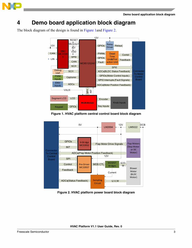
4 Demo board application block diagramThe block diagram of the design is found in Figure 1and Figure 2.
Figure 1. HVAC platform central control board block diagram
Figure 2. HVAC platform power board block diagram
MC9S12G240
GPIOs Relays
ConnectorTo Motor Control Board
ADCs(BLDC Status Feedback)
GPIOs(Motor Control Inputs )
GPIO Interrupts (Fault Signals)
ADCs(Motor Position Feedback)
SPI0
LIN
SBCMC3390
5
SCI1
SPI0
CAN
RESET
MUXOUT
INT
VDDCAN
Debug Uart
SCI1
PWM Inputs
Captures
ENV Inputs
ADCs
MC9S08LG32
SP
I1
Knob Inputs
Encoder
Key Inputs
Segment LCD LCD
Keypad GPIOs
Dead Time
Unit&Protection Unit
PWMs
GPIOsContol
Feedback Fault
12V
VAUX
Relay Driver
INT
12V
Pre‐DriverMC33937
Control
Feedback
SPI
ADCs(Status Feedback)
MOSFET Bridges
MOS CTL
H‐BridgeMC33932
GPIOs
U,V,W
Blower Motor(BLDC Motor)
Sampling Circuit
U.V,W
INTFlap Motor Drive Signals Flap Motors
(Step Motor or DC Motor)
LM5022LM2694
ADCs(Flap Motor Position Feedback)
5V 12V
12V
DCB
Current
ConnectorTo Central
Control Board
HVAC Platform V1.1 User Guide, Rev. 0
Freescale Semiconductor 3
Demo board views
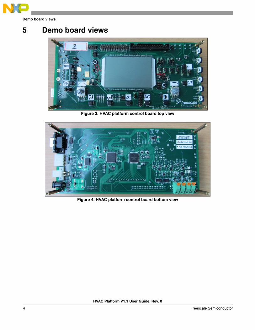
5 Demo board views
Figure 3. HVAC platform control board top view
Figure 4. HVAC platform control board bottom view
HVAC Platform V1.1 User Guide, Rev. 0
Freescale Semiconductor4
Demo board views
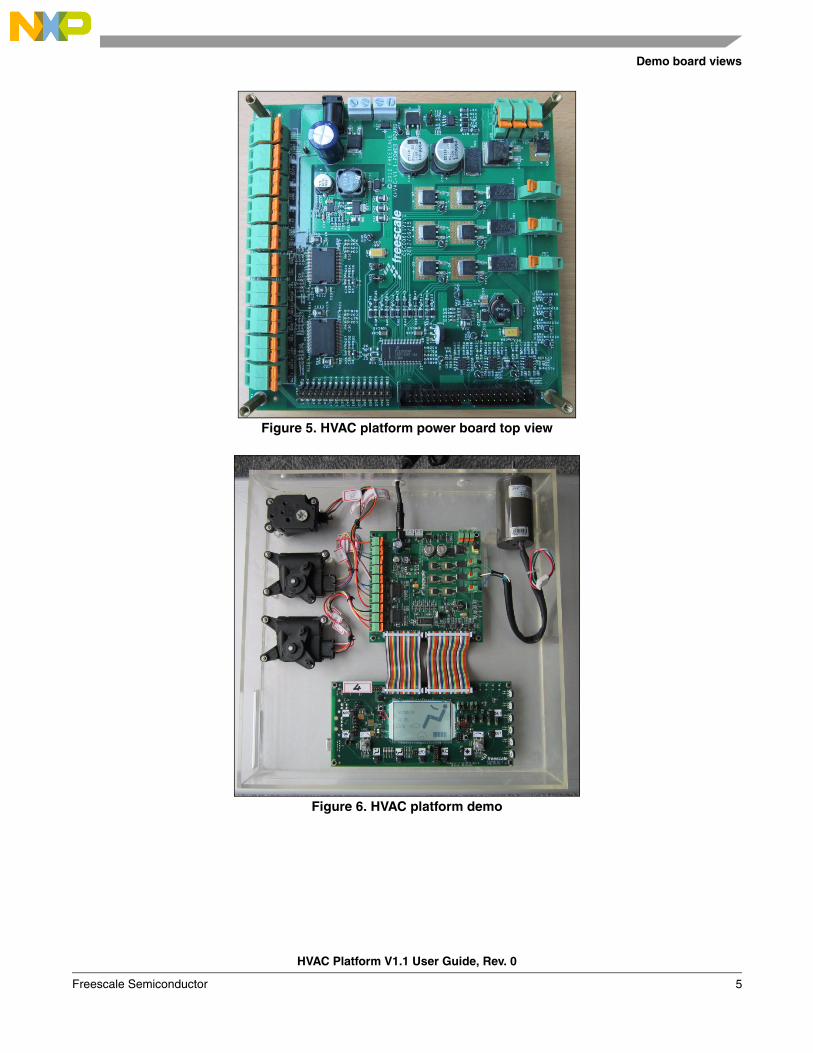
Figure 5. HVAC platform power board top view
Figure 6. HVAC platform demo
HVAC Platform V1.1 User Guide, Rev. 0
Freescale Semiconductor 5
HVAC platform demo board
6 HVAC platform demo board
6.1 Getting started with HVAC central control board
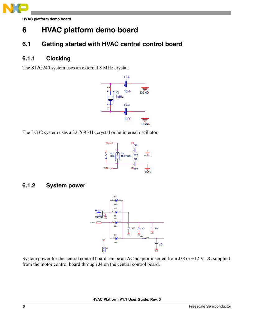
6.1.1 Clocking
The S12G240 system uses an external 8 MHz crystal.
The LG32 system uses a 32.768 kHz crystal or an internal oscillator.
6.1.2 System power
System power for the central control board can be an AC adaptor inserted from J38 or +12 V DC supplied from the motor control board through J4 on the central control board.
HVAC Platform V1.1 User Guide, Rev. 0
Freescale Semiconductor6
HVAC platform demo board
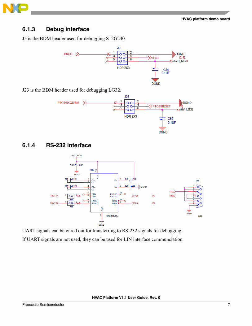
6.1.3 Debug interface
J5 is the BDM header used for debugging S12G240.
J23 is the BDM header used for debugging LG32.
6.1.4 RS-232 interface
UART signals can be wired out for transferring to RS-232 signals for debugging.
If UART signals are not used, they can be used for LIN interface communciation.
HVAC Platform V1.1 User Guide, Rev. 0
Freescale Semiconductor 7
HVAC platform demo board
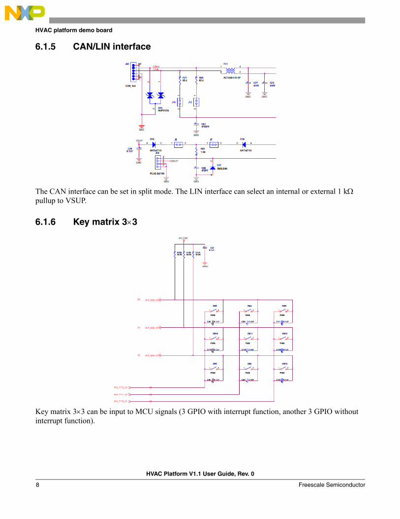
6.1.5 CAN/LIN interface
The CAN interface can be set in split mode. The LIN interface can select an internal or external 1 k pullup to VSUP.
6.1.6 Key matrix 33
Key matrix 33 can be input to MCU signals (3 GPIO with interrupt function, another 3 GPIO without interrupt function).
HVAC Platform V1.1 User Guide, Rev. 0
Freescale Semiconductor8
HVAC platform demo board
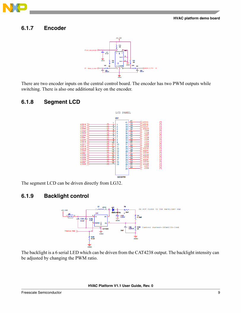
6.1.7 Encoder
There are two encoder inputs on the central control board. The encoder has two PWM outputs while switching. There is also one additional key on the encoder.
6.1.8 Segment LCD
The segment LCD can be driven directly from LG32.
6.1.9 Backlight control
The backlight is a 6 serial LED which can be driven from the CAT4238 output. The backlight intensity can be adjusted by changing the PWM ratio.
HVAC Platform V1.1 User Guide, Rev. 0
Freescale Semiconductor 9
HVAC platform demo board
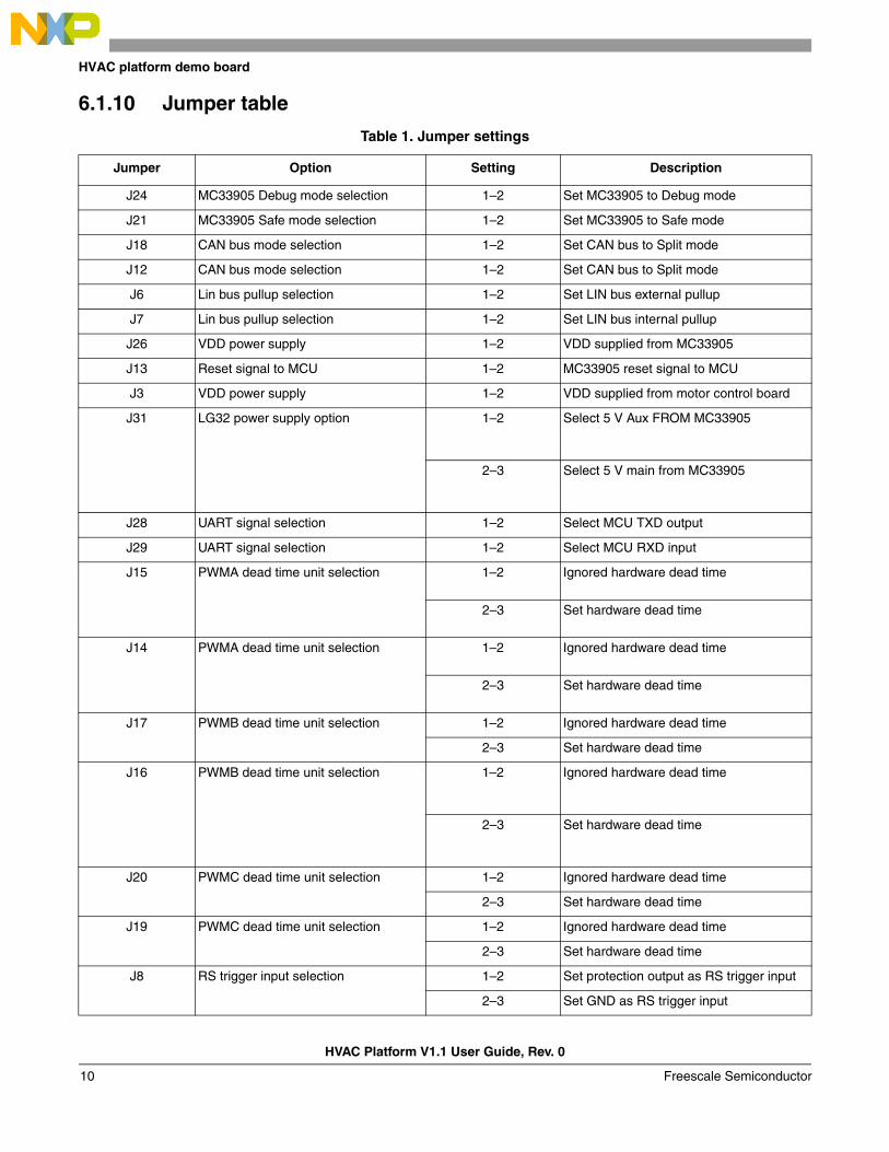
6.1.10 Jumper table
Table 1. Jumper settings
Jumper Option Setting Description
J24 MC33905 Debug mode selection 1–2 Set MC33905 to Debug mode
J21 MC33905 Safe mode selection 1–2 Set MC33905 to Safe mode
J18 CAN bus mode selection 1–2 Set CAN bus to Split mode
J12 CAN bus mode selection 1–2 Set CAN bus to Split mode
J6 Lin bus pullup selection 1–2 Set LIN bus external pullup
J7 Lin bus pullup selection 1–2 Set LIN bus internal pullup
J26 VDD power supply 1–2 VDD supplied from MC33905
J13 Reset signal to MCU 1–2 MC33905 reset signal to MCU
J3 VDD power supply 1–2 VDD supplied from motor control board
J31 LG32 power supply option 1–2 Select 5 V Aux FROM MC33905
2–3 Select 5 V main from MC33905
J28 UART signal selection 1–2 Select MCU TXD output
J29 UART signal selection 1–2 Select MCU RXD input
J15 PWMA dead time unit selection 1–2 Ignored hardware dead time
2–3 Set hardware dead time
J14 PWMA dead time unit selection 1–2 Ignored hardware dead time
2–3 Set hardware dead time
J17 PWMB dead time unit selection 1–2 Ignored hardware dead time
2–3 Set hardware dead time
J16 PWMB dead time unit selection 1–2 Ignored hardware dead time
2–3 Set hardware dead time
J20 PWMC dead time unit selection 1–2 Ignored hardware dead time
2–3 Set hardware dead time
J19 PWMC dead time unit selection 1–2 Ignored hardware dead time
2–3 Set hardware dead time
J8 RS trigger input selection 1–2 Set protection output as RS trigger input
2–3 Set GND as RS trigger input
HVAC Platform V1.1 User Guide, Rev. 0
Freescale Semiconductor10
HVAC platform demo board
6.2 Getting started with the HVAC motor control board
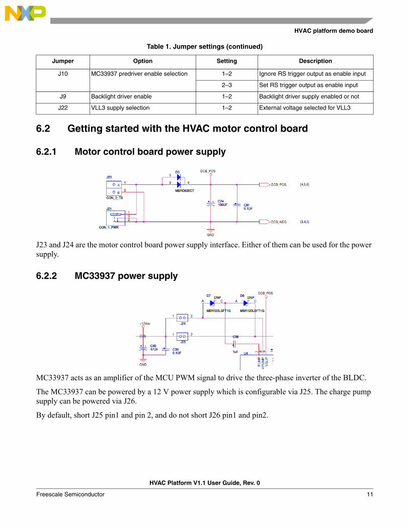
6.2.1 Motor control board power supply
J23 and J24 are the motor control board power supply interface. Either of them can be used for the power supply.
6.2.2 MC33937 power supply
MC33937 acts as an amplifier of the MCU PWM signal to drive the three-phase inverter of the BLDC.
The MC33937 can be powered by a 12 V power supply which is configurable via J25. The charge pump supply can be powered via J26.
By default, short J25 pin1 and pin 2, and do not short J26 pin1 and pin2.
J10 MC33937 predriver enable selection 1–2 Ignore RS trigger output as enable input
2–3 Set RS trigger output as enable input
J9 Backlight driver enable 1–2 Backlight driver supply enabled or not
J22 VLL3 supply selection 1–2 External voltage selected for VLL3
Table 1. Jumper settings (continued)
Jumper Option Setting Description
HVAC Platform V1.1 User Guide, Rev. 0
Freescale Semiconductor 11
HVAC platform demo board
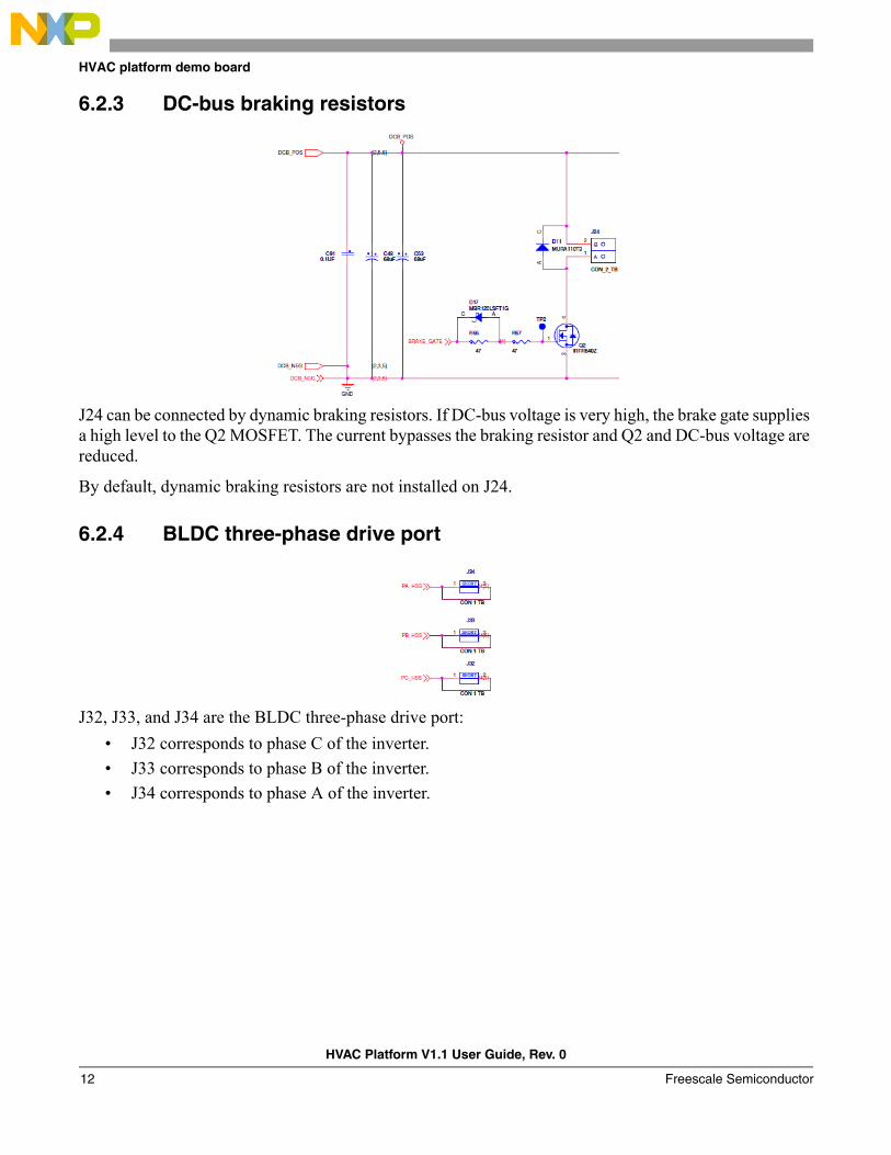
6.2.3 DC-bus braking resistors
J24 can be connected by dynamic braking resistors. If DC-bus voltage is very high, the brake gate supplies a high level to the Q2 MOSFET. The current bypasses the braking resistor and Q2 and DC-bus voltage are reduced.
By default, dynamic braking resistors are not installed on J24.
6.2.4 BLDC three-phase drive port
J32, J33, and J34 are the BLDC three-phase drive port:
• J32 corresponds to phase C of the inverter.
• J33 corresponds to phase B of the inverter.
• J34 corresponds to phase A of the inverter.
HVAC Platform V1.1 User Guide, Rev. 0
Freescale Semiconductor12
HVAC platform demo board
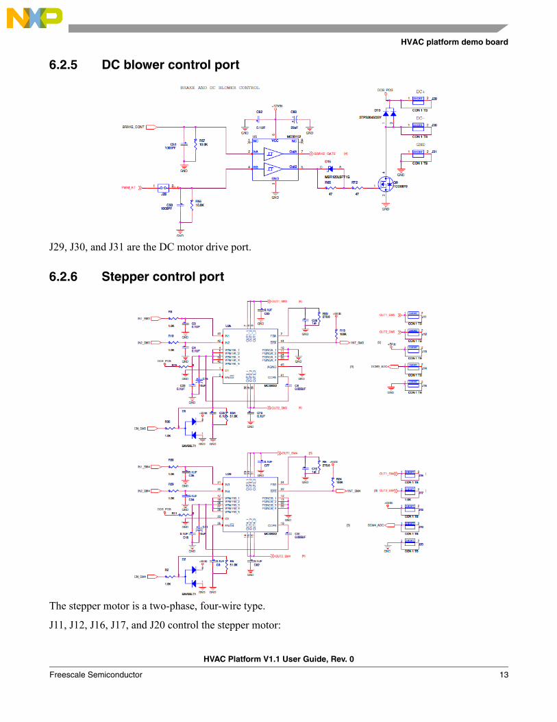
6.2.5 DC blower control port
J29, J30, and J31 are the DC motor drive port.
6.2.6 Stepper control port
The stepper motor is a two-phase, four-wire type.
J11, J12, J16, J17, and J20 control the stepper motor:
HVAC Platform V1.1 User Guide, Rev. 0
Freescale Semiconductor 13
HVAC platform demo board
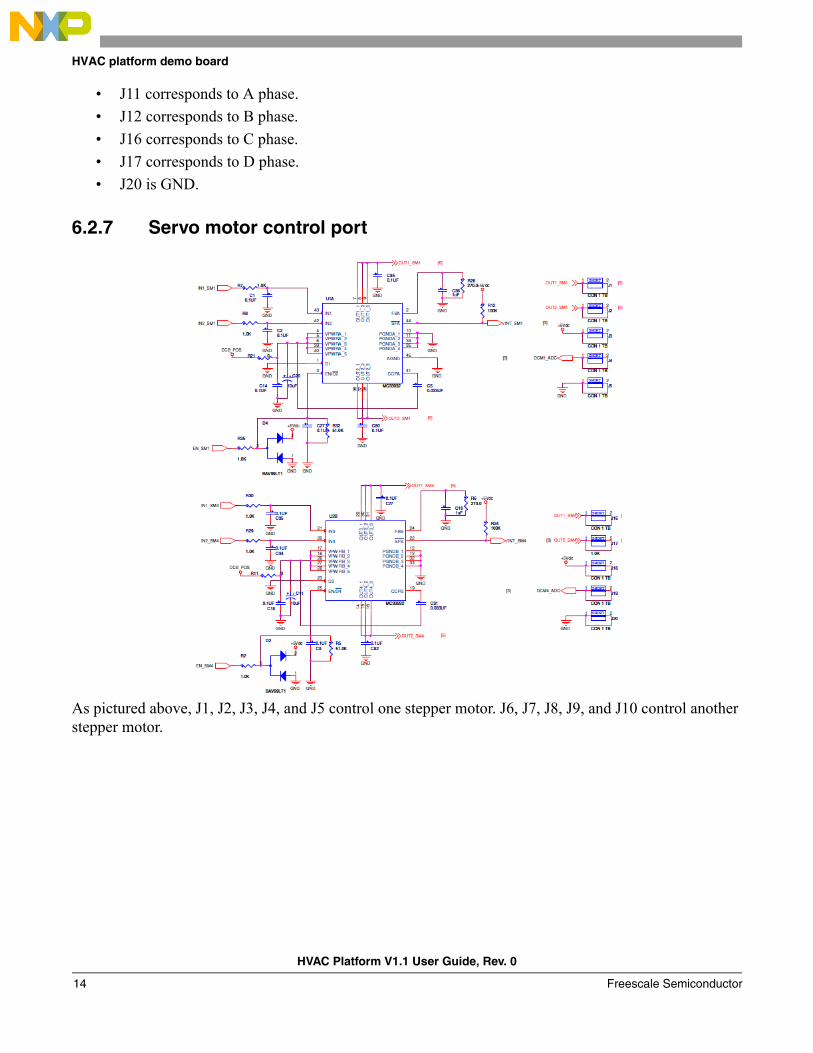
• J11 corresponds to A phase.
• J12 corresponds to B phase.
• J16 corresponds to C phase.
• J17 corresponds to D phase.
• J20 is GND.
6.2.7 Servo motor control port
As pictured above, J1, J2, J3, J4, and J5 control one stepper motor. J6, J7, J8, J9, and J10 control another stepper motor.
HVAC Platform V1.1 User Guide, Rev. 0
Freescale Semiconductor14
HVAC platform demo board
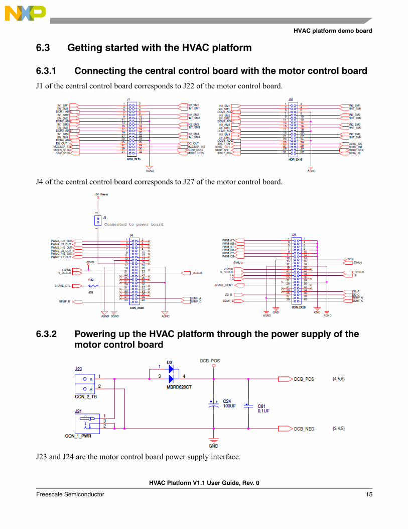
6.3 Getting started with the HVAC platform
6.3.1 Connecting the central control board with the motor control board
J1 of the central control board corresponds to J22 of the motor control board.
J4 of the central control board corresponds to J27 of the motor control board.
6.3.2 Powering up the HVAC platform through the power supply of the motor control board
J23 and J24 are the motor control board power supply interface.
HVAC Platform V1.1 User Guide, Rev. 0
Freescale Semiconductor 15
Conclusions
Powering up J23 or J24 will supply power to both motor control board and central control board.
7 ConclusionsThis document describes the basic steps for getting started with Freescale’s HVAC platform demo boards and the demo suitcase. For technical details about the board design and solution implemented, please go to www.freescale.com.
HVAC Platform V1.1 User Guide, Rev. 0
Freescale Semiconductor16
Document Number: AHVACPUGRev. 010/2012
Information in this document is provided solely to enable system and software
implementers to use Freescale products. There are no express or implied copyright
licenses granted hereunder to design or fabricate any integrated circuits based on the
information in this document.
Freescale reserves the right to make changes without further notice to any products
herein. Freescale makes no warranty, representation, or guarantee regarding the
suitability of its products for any particular purpose, nor does Freescale assume any
liability arising out of the application or use of any product or circuit, and specifically
disclaims any and all liability, including without limitation consequential or incidental
damages. “Typical” parameters that may be provided in Freescale data sheets and/or
specifications can and do vary in different applications, and actual performance may
vary over time. All operating parameters, including “typicals,” must be validated for each
customer application by customer’s technical experts. Freescale does not convey any
license under its patent rights nor the rights of others. Freescale sells products
pursuant to standard terms and conditions of sale, which can be found at the following
address: http://www.reg.net/v2/webservices/Freescale/Docs/TermsandConditions.htm
How to Reach Us:
Home Page: freescale.com
Web Support: freescale.com/support
Freescale, the Freescale logo, AltiVec, C-5, CodeTest, CodeWarrior, ColdFire, C-Ware,
Energy Efficient Solutions logo, Kinetis, mobileGT, PowerQUICC, Processor Expert,
QorIQ, Qorivva, StarCore, Symphony, and VortiQa are trademarks of Freescale
Semiconductor, Inc., Reg. U.S. Pat. & Tm. Off. Airfast, BeeKit, BeeStack, ColdFire+,
CoreNet, Flexis, MagniV, MXC, Platform in a Package, QorIQ Qonverge, QUICC
Engine, Ready Play, SafeAssure, SMARTMOS, TurboLink, Vybrid, and Xtrinsic are
trademarks of Freescale Semiconductor, Inc. All other product or service names are
the property of their respective owners.
© 2012 Freescale Semiconductor, Inc.