Embed Size (px)
Citation preview
HVAC – Domestic and Industrial Ventilation Systems Course No: M05-018
Credit: 5 PDH
A. Bhatia
Continuing Education and Development, Inc. 9 Greyridge Farm Court Stony Point, NY 10980 P: (877) 322-5800 F: (877) 322-4774 [email protected]
HVAC – DOMESTIC AND INDUSTRIAL VENTILATION SYSTEMS
Ventilation can simply be described as the process of changing air in the enclosed
space. Fresh air is introduced and circulated throughout the building and the vitiated or
stale air is removed or diluted. Ventilation is necessary in:
1. Preventing depletion of the oxygen content of the air;
2. Preventing undue accumulation of carbon dioxide and moisture;
3. Preventing an undue concentration of body odours and other contaminants such
as kitchen or tobacco smoke;
4. Preventing an undue concentration of particles carrying bacteria; and
5. Removing body heat and heat liberated by the operation of electrical, mechanical
and process equipment (e.g. artificial lighting and machinery).
The rate of ventilation, measured in cubic feet per minute (CFM) or liters of air per
second (lps) must be sufficient to satisfy the following three requirements:
1. Sufficient air movement throughout the space to prevent the formation of pockets
of stale air.
2. Sufficient fresh air supply and foul air exhaust to limit the level of air pollution
from all sources in the building, including humidity.
3. Reduction of air temperature, within the limits set by the climate, by the removal
of heat generated within the building or supplied by the sun.
This course will discuss the basic guidelines and prudent practices in the design of
ventilation systems. The course is divided into 6 sections:
Section -1: General Purpose Ventilation
Section -2: Types of Ventilation Systems
Section -3: Ventilation Strategies for Indoor Air Quality
Section -4: Estimating Ventilation Rates
Section -5: Industrial Ventilation
Section -6: General System Design Considerations
SECTION -1: GENERAL PURPOSE VENTILATION
General Purpose Ventilation involves removing heat, odors, and/or contaminated air
from inside the building and replacing it with outside air. It may be provided by natural
draft, by exhaust fans, by supply fans or by a combination of supply and exhaust fans.
Although natural ventilation is often relied, its effects are uncertain, unreliable and
difficult to control. Mechanical ventilation system using fans have become an essential
part of good ventilating systems for the following reasons:
1. They operate irrespective of internal temperature and external winds.
2. They can be more easily and accurately controlled.
3. They can often be used for either extract or intake, and therefore cater for a
wider variety of winter and summer conditions more easily.
4. On extract, much smaller inlet openings are necessary in building structures for
air replacement, due to the greater suction pressure provided by a fan.
5. On intake, they give positive air movement for relief from radiant heat;
incorporate filters for use in dusty atmospheres, and act as heaters (if required)
during cold weather to augment the normal heating system of the building.
General or dilution ventilation is not an adequate alternative to containment of an
impurity at source. This is done by local exhaust ventilation. However, it may be
necessary to dilute the impurity to an acceptable level where complete control at source
is not reasonably practical. These aspects are discussed in detail in Section 5.
Factors Affecting Ventilation Rates
The need for fresh air in the workplace is influenced by a number of factors; in particular
the space available per occupant, the work activity, the habits of the occupants (e.g.
smoking) and the presence of other sources of airborne contaminants such as process
plant, heaters, etc.
Quantity and Distribution of Air: The fresh air supply is required to maintain an
acceptably non-odorous atmosphere (by diluting body odors and tobacco smoke) and to
dilute the carbon dioxide exhaled. The quantity may be quoted per person and is related
to the occupation density and activity within the space. The proportion of fresh air
introduced into a building may be varied to achieve economical operation. When the
fresh air can provide a useful cooling effect, the quantity is controlled to balance the
cooling demand. However, when the air is too cool, the quantity is reduced to a minimum
to limit the heating load. Similarly, when the air is too warm or humid, the quantity is
reduced to minimum to reduce the cooling load.
Transfer of heat/moisture: Air circulation is required to transfer the heat and humidity
generated within the building. In simple systems, the heat generated by the occupants,
solar heat, and heat from electrical and mechanical equipment may be removed by the
introduction and extraction of large quantities of fresh air. In more elaborate systems air
may be recirculated through conditioning equipment to maintain the desired temperature
and humidity. The air circulation rates are decided in relation to the thermal or moisture
loads and the practical cooling or heating range of the air.
Air movement: Air movement is desirable, as it contributes a feeling of freshness,
although excessive movement should be avoided as this leads to complaints of
draughts. The speed of an air current becomes more noticeable as the air temperature
falls, owing to its increased cooling effect. The design of the air-distribution system,
therefore has a controlling effect on the quantity and temperature of the air that can be
introduced into the space. The quantity of fresh air should not be increased solely to
create air movement; this should be affected by air recirculation within the space or
inducing movement with the ventilation air stream.
Air-flows within the building should be controlled to minimize transfer of fumes and
smells, e.g. from kitchens to restaurants and the like. This is achieved by creating air
pressure gradients within the building, by varying the balance between the fans
introducing fresh air and those extracting the stale air. For example, the pressure should
be reduced in a kitchen below that of the adjacent restaurant. Care should be taken,
however, to avoid excessive pressure differences that can cause difficulty in opening
doors or cause them to slam. In other cases, such as computer rooms, the area may be
pressurized to minimize the introduction of dust from adjacent areas.
Fire and smoke control: Air circulation system may be designed to extract smoke in
the event of a fire, to assist in the fire-fighting operations and to introduce fresh air to
pressurize escape routes.
Air purity and filtration: A ventilation or air-condition system installed in a building
should clean, freshen or condition the air within the space. Special air filters may be
required to remove contaminants or smells when air is recirculated. Positions of air inlets
and extracts to the system are most important and care should be taken in their location.
Inlets should not be positioned near any flue outlets, dry cleaning or washing machine
extraction outlets, kitchens, WC’s, etc. When possible, air inlets should be at high level
so as to induce air from as clean an area as possible. If low level intakes are used, care
should be taken to see that they are positioned well away from roadways and car parks.
Climatic Conditions: Ventilation systems must be considered for three climatic
conditions that occur during the year: winter, summer and spring-fall. A high rate of
ventilation is required in the summer to deal with the build-up of heat from solar
radiation, production processes, and high internal heat loads; whereas, in winter a very
low air change per hour (ACH) is required to prevent vitiation of the air and to remove
odours and water vapor. (ACH is the number of air changes per hour is the number of
times one volume of air is replaced in the space per hour.) This variation in requirements
may range from 6-15 ACH in summer and 2 ACH in winter.
Winter Ventilation
A heating system with adequate capacity is needed in the winter to maintain
environmental conditions inside the building. Even during the coldest part of the winter,
when the heating system is running at full capacity, some ventilation is still required.
Fresh outside air must be introduced into the building to remove the warm, moisture-
laden air. If moist air is not removed, high humidities and excessive condensation will
occur. Studies have shown that humidities over 90% foster rapid deterioration of
structural components, as well as dampness and uncomfortable environmental
conditions.
Condensation occurs when warm humid air comes into contact with cold surfaces, such
as glass or structural members. The air in contact with the cold surface is cooled to the
temperature of the surface. If the surface temperature is below the dewpoint temperature
of the air, then water vapor in the air will condense onto the surface. For example,
condensation occurs if indoor air at 70°F and 70% relative humidity comes in contact
with a surface that is 60°F or colder. This tendency is increased with low ambient
temperatures, high wind velocities and high internal humidities.
Exhausting moist air and replacing it with heated outside air is effective in eliminating
condensation and other problems resulting from high humidities. Whenever ventilation
rates are increased in the winter, the heating requirements also increase. Consequently,
it is necessary to determine a ventilation rate that will maintain humidities below the
damaging level and, at the same time, keep the heating requirements as low as
possible. Ventilation requirements in winter are generally on the order of two to three air
changes per hour. The higher the inside temperature, the lower shall be the air
exchange rate that is required to maintain humidities below the damaging level. Besides
controlling humidity, this minimum ventilation rate is required to remove any gases of
combustion that may be present as a result of leakages around the heater and ducting
when a direct-fired heating system is used.
To conserve energy in winter, the ventilation shall operate under reduced flow to take
advantage of increased air infiltration. The ventilation fans could be equipped with a flow
controller such as a two-speed fan. A manual switch or an indoor humidistat could be
used to increase flow for quick removal of odors, moisture and fumes. In addition, an
outdoor temperature controller could be installed to increase air flow in mild weather.
Summer Ventilation
The main purpose of a ventilation system during the summer is to prevent the air
temperature rising too high above the outside air temperature. The reason for the higher
air temperature indoors may be because of the large influx of solar radiation and large
dissipation of heat by power and process equipment. The amount of sensible heat gain
is essentially from four components:
• Q1 = Solar heat gain through structure
• Q2 = Heat from the electrical apparatus/machinery
• Q3 = Heat dissipation from other equipment/processes
• Q4 = Body heat of occupants
The total heat gain is Σ Q = Q1 + Q2+ Q3 + Q4
The ventilation rate can than be calculated from equation:
V = Q / (1.08 * ∆T)
Where:
1. Q = sensible heat load (Btu/h)
2. V = volume flow rate of outdoor air introduced in cubic feet per minute (cfm)
3. ∆T = temperature difference between outdoor and indoor air °F
4. 1.08 = A constant derived from the density of air at 0.075 lb/cu ft under average
conditions, multiplied by the specific heat of air (heat required to raise 1 lb of air
1°F) which is 0.24 Btu/lb°F, and multiplied by 60 min/h. The units of this constant
are Btu min/cu ft °F h.
The ventilation calculation is an iterative process as there are two variables V and ∆T.
Setting different values of ∆T will provide different cfm values. Fixing ∆T is basically
setting the value of indoor air temperatures as the design outdoor air temperatures can
be obtained from ASHRAE handbook of fundamentals, which provides weather data for
various geographical locations. As the temperature difference between outside and
inside air temperature decreases, the ventilation rate increases. Regardless of how high
the ventilation rate is in the summer, the inside air temperature during the day will never
be as low as the outside air temperature. The inside air temperature can at best
approach outdoor ambient temperature at very high ventilation rates. But the
disadvantage of increasing the ventilation rate is the increased cost for fans and
accessories, as well as increased operating costs. If one is interested in maintaining an
inside air temperature below outside air temperature, then evaporative cooling or some
other means of refrigeration must be used.
Generally accepted ventilation rates for temperature control in the summer range from
one air change every three minutes to three air changes per minute.
Spring-Fall Ventilation
The recommended ventilation rates for the spring-fall seasonal periods will be
somewhere between rates required for summer temperature control and those required
for winter-humidity control. The spring-fall periods are characterized by being some
times relatively cool and cloudy and other times warm and sunny. No special provisions
are necessary for maintaining ventilation rates during this period except for the
temperature and humidity controls that will determine the amount of ventilation
necessary.
Ventilation for Air Quality
The sources for odor are many: body odors, tobacco smoke, vehicle exhaust, food
preparation, garbage, finishing materials, furnishings and even the wetted coils of air
conditioning systems as they become dirty. There are a number of other items that can
affect indoor air quality; from cigarette smoke to ozone from laser printers. All of these
can add to the challenges of maintaining good indoor air quality. A variety of airborne
particles, such as dust, smoke, pollens and organisms are contained in the outdoor air
and are brought indoors along with the ventilation air. Many contaminants are generated
indoors by the activities of the occupants. Limiting the concentrations of these
contaminants is an important aspect of air quality control.
There are two basic methods of ventilation for air quality control. The simplest and most
widely accepted technique for controlling odors is to dilute them with outdoor air. A
sufficient amount of fresh air is brought into the space, adequately mixed with the room
air to reduce the concentration, and then exhausted from the room in the mixed
condition.
If the source of the contaminant can be isolated, a second approach may use the dilution
method as well as isolation or removal of particles through dedicated exhaust systems.
This is the approach used with kitchen range hoods and in venting fuel-fired systems,
where the products of combustion are captured and exhausted with draft control air up
the chimney.
A modification of the dilution approach involves recycling and conditioning the air by
passing it through a device that will remove the offending contaminant or odor, and
return the freshened air to the occupied space. A common example of this approach is
the recirculation of indoor air through a filter or gaseous filtration based on the principle
of adsorption. The adsorbent material is usually activated charcoal which is very
effective in removing the volatile organic compounds (VOC’s). This technique is much
more effective compared to dilution when the nature of contaminant is known. This is
discussed further in detail in Section 3.
Ventilation for Humidity Control
Buildings, like our bodies, exchange moisture and air with the environment, as well as
exchange heat. Although most of this moisture exchange occurs during the exchange of
fresh air, some exchange occurs through a building's skin. This can cause problems in
either hot, humid climates or very cold ones.
In hot and humid conditions, as hot and humid air contacts cold surfaces, condensation
can occur. Almost all common building materials, including gypsum board, concrete, clay
masonry, wood, etc. are easily permeated by moisture. Most surface finishes are also
permeable. The moisture vapor in the air condenses to visible droplets of water on the
ceiling. A much less visible moisture threat occurs within walls, ceilings or floors. The
results can be annoying and more serious damage to the building structure can result.
In cold climates, the air outside contains relatively little moisture even though the RH
may be high. By contrast, inside air contains much more moisture per unit of volume
despite its probably lower RH. The result is a flow of vapor from high vapor pressure to
low vapor pressure (typically warm to cold). Such a flow occurs when the temperature
within the wall (floor, etc.) drops low enough for this vapor to condense. Insulation can
then become wet and thereby less effective, since water conducts heat far better than
the air pockets. Worse yet, moisture damage can occur, such as dry rot in wood
structural members. The usual remedy for such a potential problem is to install a vapor
barrier within the building envelope. These barriers are commonly made of plastic film
installed with as few holes as possible.
Outdoor air is always infiltrating a building, gradually replacing the indoor air. This
unintentional source of fresh air becomes a problem when temperatures outside are very
different from those inside, especially when strong winds force outdoor air indoors fast
enough to produce noticeably cold (or hot) drafts. Some fresh air is always desirable in
buildings, but it should be the user’s control of how and where it is admitted.
Humidity control strategies will depend on the climate of the region and its seasonal and
daily cycles. Surface condensation is sensitive to daily variations in climate and
operation.
Ventilation for humidity control is least effective in the fall because the drying capacity of
the outside air is at a minimum and the moisture supply rate is highest, due to moisture
given off from storage in furnishings and building materials.
Lowering the relative humidity inside the house in summer, using an air conditioner or
dehumidifier, will lower the moisture content of the interior materials and thus the
moisture supply from storage in fall and winter.
Introducing colder, drier outside air to the space in winter serves to dilute the water
vapor, enabling the drier mixture to pick up moisture produced in the space, and to
exhaust the mixture either up the chimney through an exhaust fan or by exfiltrating
through the house envelope. The rate of moisture removal by this means will depend on
the moisture content of the outdoor air and the rate of flow of the room air to the outside.
In general, a minimum continuous ventilation rate of 35 liters per second is
recommended to maintain air quality in houses under normal circumstances, with a
capability of 75 liters per second or more for intermittent use for humidity control and
contaminant removal. Natural forces cannot be relied upon to provide such rates under
all circumstances and a positive, mechanical system is desirable.
Always provide dedicated exhaust fans in high moisture production areas, such as the
bathroom and the kitchen. It is also the principle employed in the automatic clothes
dryer, where room air is brought in to pick up moisture from the wet clothes and exhaust
it to the outside. Another approach to indoor humidity control would be to use a device to
remove moisture from the air by absorption or condensation and return the dried air to
the space. A typical example of this is the indoor dehumidifier. Since its capacity is
markedly reduced at low humidities, it is not capable of removing much moisture below
indoor relative humidities of 40%. It could, however, be effective in helping to control
indoor humidity levels in those areas where 40% can be tolerated and where higher
humidities are experienced.
______________________________________________________________________
SECTION -2 TYPES OF VENTILATION SYSTEMS
The three common ventilation system designs are:
1. Mechanical Ventilation, which can be further classified as the extract system,
intake supply system, and balanced ventilation system.
2. Displacement Ventilation, which either uses the principle of natural ventilation of
supplying fresh air at lower levels and exhausting at higher elevations, or
mechanically introducing air at lower levels and exhausting at higher elevations.
3. Natural Ventilation using the principles of building stack effect.
In the interest of efficient use of energy, health & safety, and comfort of the occupants, it
is imperative that all systems of ventilation be considered in relation to the thermal
characteristics of the building.
Mechanical Ventilation
There are three primary types of mechanical ventilation systems: 1) Mechanical
extract/natural supply system, 2) Mechanical supply/natural extract system, and 3)
Combined mechanical supply/extract system or balanced ventilation system.
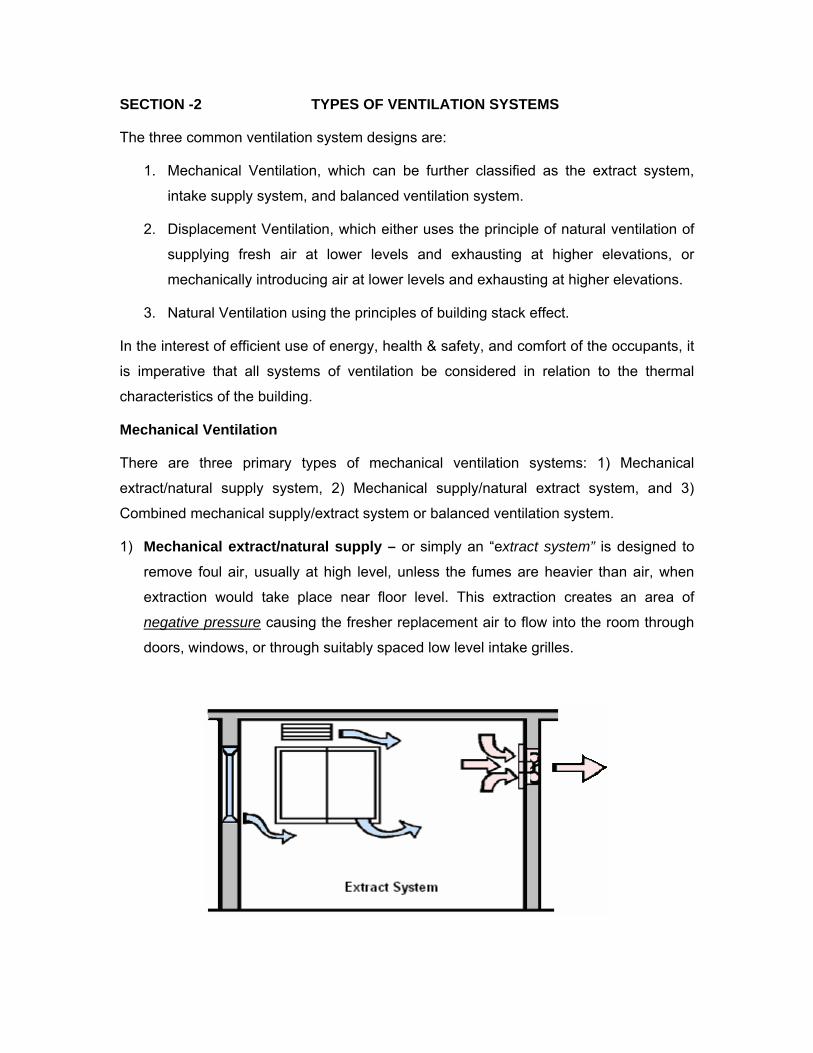
1) Mechanical extract/natural supply – or simply an “extract system” is designed to
remove foul air, usually at high level, unless the fumes are heavier than air, when
extraction would take place near floor level. This extraction creates an area of
negative pressure causing the fresher replacement air to flow into the room through
doors, windows, or through suitably spaced low level intake grilles.
The simplest form of extract system comprises one or more fans (usually of the
propeller axial flow or mixed flow type) installed in outside walls or on the roof. The
discharge usually terminates in louvers or a cowl or a combination of both.
Alternatively, the system may comprise a range of ductwork arranged for general
extraction of the vitiated air or for extraction from localized sources of heat, moisture,
odors, fumes and dust. Such ductwork may be connected to centrifugal or axial flow
fans that discharge through the wall or roof, terminating in louvers or cowls or a
combination of both. The ductwork includes suitable extract points and dampers.
An exhaust ventilation system requires the replacement of exhausted air by way of
make-up air. Replacement air can be supplied naturally by atmospheric pressure
through open doors, windows, wall louvers, and adjacent spaces (acceptable),
through cracks in walls, windows, and beneath doors, and through roof vents
(unacceptable). Make-up air can also be provided through dedicated replacement air
systems.
The exhaust system reduces the potential for wall and roof moisture problems but it
shouldn’t be used if filtered air is required in the space, as it would not be possible to
filter all incoming air due to any uncontrolled leakage through cracks around doors
and windows. This system can increase the potential for cold drafts due to its
depressurization effect, and, unless exhaust pickups are judiciously placed, tends to
provide poor air distribution.
An extract system can also be regarded as a palliative measure to meet the need for
ventilation in particularly crowded rooms, offices or restricted areas in which local
conditions are likely to prove objectionable; for example in toilets, kitchens, plant
rooms, workshops or laboratories, or where there is a statutory requirement for
exhaust ventilation.
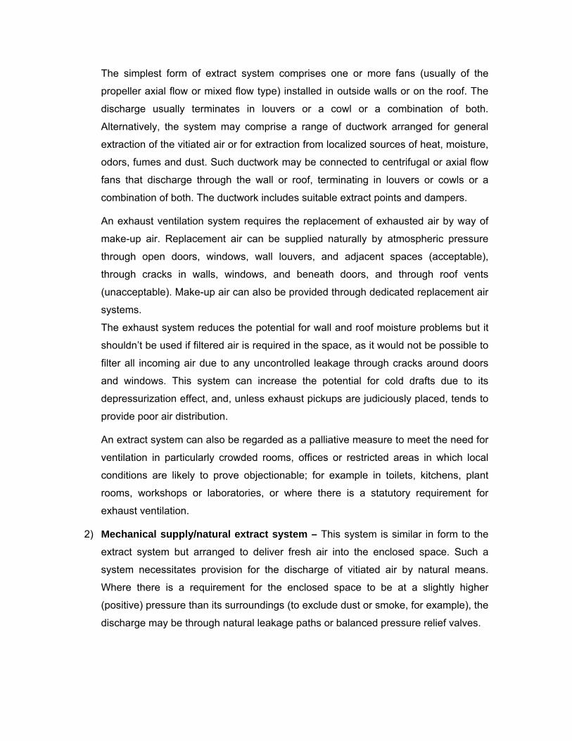
2) Mechanical supply/natural extract system – This system is similar in form to the
extract system but arranged to deliver fresh air into the enclosed space. Such a
system necessitates provision for the discharge of vitiated air by natural means.
Where there is a requirement for the enclosed space to be at a slightly higher
(positive) pressure than its surroundings (to exclude dust or smoke, for example), the
discharge may be through natural leakage paths or balanced pressure relief valves.
Careful location and speed control of intake fans and evenly distributed air supply
diffusers are necessary to prevent draughty conditions. Ducted supply systems can
provide better control of air movement and reasonable control of comfort conditions.
A mechanical supply system is essential where area is to be maintained at positive
pressure and/or if the filtered air is required. This system tends to pressurize the
building interior and lower the neutral pressure level. (The neutral pressure level is a
level in a building where the interior and exterior pressures are equal). By lowering
the neutral pressure level, it reduces both the envelope area subject to infiltration
and the inward pressures that drive infiltration airflow. However, the outward
pressures and the envelope area subject to exfiltration are increased which tends to
increase the total exfiltration airflow.
The serious disadvantage of this approach is its increased potential for driving
moisture-laden interior air into the wall and roof cavities, where it can condense and
cause problems such as mold growth, rot, and peeling paint. This system should
therefore be only used in a building with a very good air barrier. In colder regions of
the country, the fresh air supply duct may require a duct heater to preheat the fresh
air to prevent condensation on the furnace heat exchanger and cold drafts on the
building's occupants. If the supply inlet is improperly located, sound can be
transmitted into the building through the ventilation system.
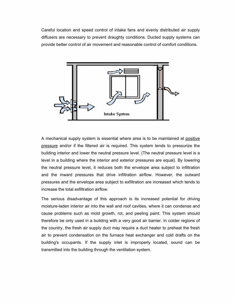
3) Combined mechanical supply/extract system – A combined system draws in
fresh air from the exterior and discharge stale air from the interior in equal amounts.
The balanced flow supply-exhaust ventilation system incorporates a central supply
fan and a central exhaust fan. Balanced systems are only suitable for more airtight
buildings where mechanical assistance is required to both supply and exhaust air;
that is, where the building envelope is sufficiently tight to reduce air leakage to a
level where it cannot provide adequate supply air by infiltration or exhaust flow by
exfiltration.
When this type of system operates in a balanced condition, it has no net effect on the
building's pressure distribution or the neutral pressure level; neither raising it nor
lowering it. However, conditions often result in a "balanced" system operating in an
unbalanced way, such as a net-exhaust or net supply system. For example, if the
inlet screens of the supply fan become partially blocked, a net-exhaust situation may
result. If the incoming air is very cold, it will warm up and expand as it enters the
living space, resulting in a larger effective supply flow rate and a net-supply situation.
Where the exhaust duct of an air-to-air heat exchanger becomes partially obstructed
by frost build-up, the exhaust flow rate would be reduced and a net-supply situation
would also result. Generally, exhaust systems are interlocked with a dedicated
make-up air system.
Advantages of balanced combined systems
1. This type of system can provide high ventilation rates without large heating costs,
if heat recovery ventilators are incorporated in the ventilation system.
2. Though the system does not affect the building's pressure balance, the larger
ventilation rates possible with this type of system can reduce the indoor humidity
levels and thus the potential for wall and roof moisture problems.
3. The larger and continuous ventilation rates can also help reduce the potential
hazard from radon entry and chimney spillage, should they occur, by diluting the
resulting indoor air contaminants.
4. This type of system provides very good air distribution, and is particularly suitable
for automatic controls.
5. A balanced ventilation system has no additional need for a make-up air supply,
so extra penetrations of the envelope are not necessary.
Disadvantages of balanced systems
1. The system is difficult to balance and may require a certified installer; further
increasing the cost. Its maintenance requirements (inspection and cleaning) are
extensive so operating costs can also be quite high.
2. This system is suitable primarily for new building construction; the envelopes of
older buildings tend to be sufficiently leaky that natural infiltration and exfiltration
would short-circuit the mechanical system. Its installation as a retrofit measure is
usually not practical.
Choice of Mechanical System
Supply-only (intake-only) systems are more susceptible to condensation problems. The
exfiltration of warm, humid air from these buildings occurs mainly through unintentional
leakage paths in the building envelope. As a result, excess moisture can condense and
be absorbed by the building materials at the lower temperatures encountered outside the
vapor barrier. For this reason, a supply-only system is not recommended.
The choice is essentially between a balanced system and an exhaust-only system.
Normally, a balanced system is suited to houses with fireplaces or fuel-fired heating
appliances, or where radon gas or other contaminants may collect in the building
structure. Otherwise, because of its low initial cost, an exhaust-only system is quite
satisfactory unless the house is too tight.
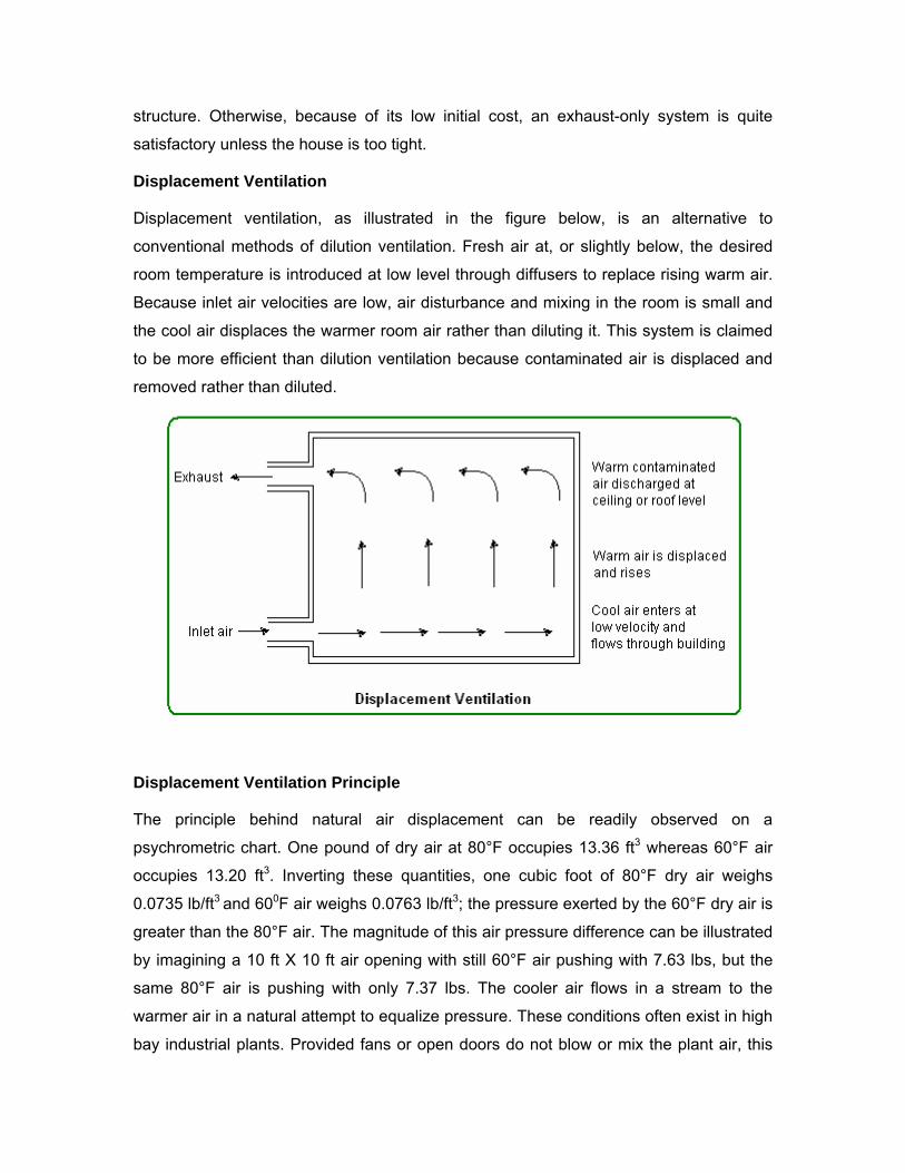
Displacement Ventilation
Displacement ventilation, as illustrated in the figure below, is an alternative to
conventional methods of dilution ventilation. Fresh air at, or slightly below, the desired
room temperature is introduced at low level through diffusers to replace rising warm air.
Because inlet air velocities are low, air disturbance and mixing in the room is small and
the cool air displaces the warmer room air rather than diluting it. This system is claimed
to be more efficient than dilution ventilation because contaminated air is displaced and
removed rather than diluted.
Displacement Ventilation Principle
The principle behind natural air displacement can be readily observed on a
psychrometric chart. One pound of dry air at 80°F occupies 13.36 ft3 whereas 60°F air
occupies 13.20 ft3. Inverting these quantities, one cubic foot of 80°F dry air weighs
0.0735 lb/ft3 and 600F air weighs 0.0763 lb/ft3; the pressure exerted by the 60°F dry air is
greater than the 80°F air. The magnitude of this air pressure difference can be illustrated
by imagining a 10 ft X 10 ft air opening with still 60°F air pushing with 7.63 lbs, but the
same 80°F air is pushing with only 7.37 lbs. The cooler air flows in a stream to the
warmer air in a natural attempt to equalize pressure. These conditions often exist in high
bay industrial plants. Provided fans or open doors do not blow or mix the plant air, this
still air seeks its own thermal level with 80°F air at the ceiling and 60°F air on the floor.
Then when a 10 ft X 10 ft opening placed low near the floor let’s tempered 60°F outdoor
air slowly flow in, a standing pool of fresh air above the floor level will form. As heat from
processes, people or heaters increase the air temperature, this heated air, at say 80°F,
flows to the peak of the ceiling where a stack or roof opening vents this warm air
outdoors. This natural draught system is powered solely by the heat added in the plant
to increase the air temperature resulting in a lower air pressure at the ceiling than at the
floor. These natural convection and air displacement systems work well when: 1) Cool
air enters low at floor level where it stays, 2) Fresh air enters slowly to prevent mixing
with plant air, and 3) Heat from any source is added within the ventilated area.
Displacement Ventilation - Benefits
No Drafts- Air is typically supplied near the floor in the space at extremely low velocity,
which results in no “throw” of air and subsequently little risk of “drafts”.
Stratified Room Air- Supply air is purposely not uniformly mixed throughout the space.
It is intentionally stratified vertically to provide a better quality of air in the occupied part
of the facility. Supply air is delivered during occupancy at temperatures slightly lower
than desired area temperature. The supply air moves horizontally across the floor until it
naturally rises, driven by convective currents as it warms due to internal heat from the
process, people, lights, computers, etc.
The space achieves superior flushing of room generated contaminants with an overall
room ventilation rate of only 1.5 air changes per hour. This is less than half the
ventilation rate that would be needed with a conventional mixing design, drastically
lowering electrical energy use through reduced fan horsepower consumption due to less
air movement.
Improved Effective Ventilation- Because of both people and process convective
currents, in a high density or industrial application, there is a general upward flow of
effluents above the occupied zone, as long as it is not greatly disturbed by fan forced air
streams (as happens in conventional mixing distribution systems). Air rises from the
lower level of the room around stationary processes due to the development of
convective currents over power consuming machinery. This means that occupants
located in the lower levels of a room will breathe air closer to supply air conditions, rather
than the air being exhausted from the space at the ceiling level, thereby improving
ventilation effectiveness.
Individual Room VAV Not Needed- When there are few or no internal loads, such as
an unoccupied area with the lights off and little solar gain, the area air will be slowly
displaced upward by the air beneath it. In this case, the area will eventually be
approximately the same temperature as the supplied air, which is only slightly cooler
than the desired temperature, thus the need for individual area (variable air volume) VAV
to prevent overcooling is virtually eliminated. “Demand control” of the total air supply to
particular areas via temperature and Carbon Dioxide sensors is utilized to minimize
energy use and fan horsepower during cold weather or low occupant density, and to
supply higher rates of ventilation only when needed.
Reduced Cooling Capacity Needed- Thermal stratification also allows for some
reduction of internal cooling requirements, because about 50% of the heat from the
lights and other sources located above the occupants does not reach the occupied zone
and, in this design, is exhausted outdoors when not needed.
Less Fan Horsepower Needed- In this design approach, supply airflows needed to
achieve adequate temperature control and provide adequate ventilation are often lower
than a conventional system. Thus, lower fan horsepower than conventional mixing type
systems is needed.
Less Room Noise- Low velocity supply of air cannot be accomplished using
conventional ceiling mounted mixing type diffusers, conventional heating ventilators (air
make-up units), or non-ducted fan coils. With reduced total air flow quantities and low
exit velocities, there is reduced noise when compared to mixing type systems, because
there is no need to forcefully mix air in the room, and less total airflow is needed.
Less Inter-zone Pollutant Transport- The supply air “quality” to individual areas is
also improved because, with a 100% outdoor air, the supply air is not already premixed
with contaminated air which has been transported from other areas or zones of the
building.
Displacement Ventilation – Limitations
Several practical difficulties exist for displacement ventilation systems, including:
1. In some cases, larger quantities of supply air may be required.
2. Because of the high supply air temperature, indoor humidity must be carefully
controlled.
3. Displacement ventilation systems may not be appropriate when contaminants are
heavier than air, or not associated with heat sources.
4. When very high loads exist, a displacement system will require uncomfortably
cold supply air. Therefore, displacement ventilation may not be appropriate in
extremely warm climates.
5. Performance of the displacement system is dependent upon ceiling height.
Displacement ventilation may not be appropriate in spaces with low ceilings.
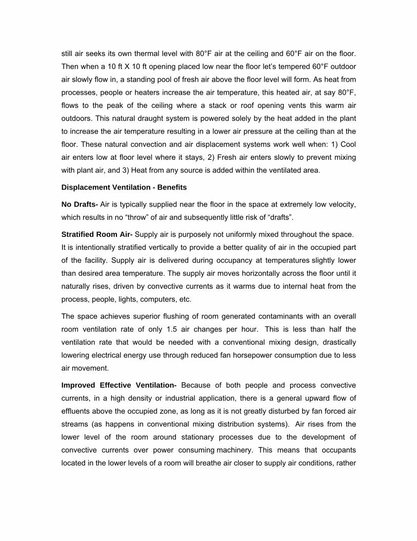
Natural Ventilation – Building Stack Effect
Many buildings use the principles of buoyancy or stack effect for air movement. When
there is a difference in height between inlet openings situated low in the wall (or in floors)
and outlets through roofs, and when outdoor air is cooler than indoor air, natural
ventilation will occur through the stack effect of warm air rising and leaving through the
higher openings. The warm air rises naturally, producing air movement through the
building. As heated air escapes from upper levels of the building, indoor air moves from
lower to upper floors, and replacement outdoor air is drawn into openings at the lower
levels of buildings. Without mechanical ventilation (refer to the figure below), the outdoor
air pressure is greater than the indoor pressure at the lower levels; the opposite is true at
the upper levels.
There is a level in a building where the interior and exterior pressures are equal and it is
called the neutral pressure level. Below the natural pressure level air infiltration occurs
and above it air exfiltration occurs. Measurements indicate that the total ventilation air
supply rate increases as the outdoor air temperature decreases. It also increases with
wind speed, but in cities with cold climates, this effect is masked by the large indoor-
outdoor temperature differences during the winter months. Natural ventilation systems
are most applicable when internal heat loads are high, and the building is tall enough to
produce a significant stack effect.
The equation below is used in calculating ventilation (or infiltration) due to the stack
effect:
In this equation:
• Q = air flow (cfm)
• C = constant of proportionality = 313 (This assumes a value of 65 percent of the
maximum theoretical flow, due to limited effectiveness of actual openings. With
less favorable conditions, due to indirect paths from openings to the stack, etc.,
the effectiveness drops to 50 percent, and C = 240.)
• A = area of cross-section through stack or outlets in sq ft. (Note: Inlet area must
be at least equal to this amount)
• ti = (higher) temperature inside (°F), within the height h
• to = (lower) temperature outside (°F)
• h = height difference between inlets and outlets.
The real advantages of a natural ventilation system are related to economics:
1. No expenses incurred for ventilation equipment, electrical operation and
maintenance.
2. No problems created by "brown-outs" or "black-outs" caused by storms or
insufficient generation capabilities.
Stack effect in buildings can have negative effects on IAQ, i.e. the temperature
differences, uncontrolled interior pressure differentials, and reduced ventilation. Stack
effect airflow can transport contaminants between floors by way of stairwells, elevator
shafts, utility chases, or other openings. The building and system designs should be able
to counterbalance this effect.
Natural Ventilation – Wind Effect
Wind velocity and direction tend to be uncontrollable factors. Air flow due to wind around
or over a building will create areas in which static pressure will be different than the
pressure of the undisturbed air flow. Wind effects are transient, creating local areas of
high pressure (on the windward side) and low pressure (on the leeward side) of
buildings. On the remaining sides, static pressures will be positive or negative to lesser
degrees depending upon the direction of air flow. The terrain surrounding the building
can also create wind flow changes affecting building pressures. Surface roughness of
the surrounding terrain (the size and location of surrounding buildings) influences the
relationship of wind velocity to building height, which will affect the pressure patterns
around the building's exterior, including the roof.
Depending on the leakage openings in the building exterior, wind can affect the pressure
relationships within and between rooms. Even when the building as a whole is
maintained under positive pressure, there is always some location (for example, the
outdoor air intake) that is under negative pressure relative to the outdoors. Entry of
contaminants may be intermittent, occurring only when the wind blows from the direction
of the pollutant source. The interaction between pollutant pathways and intermittent or
variable driving forces can lead to a single source causing IAQ complaints in areas of
the building that are distant from each other and from the source.
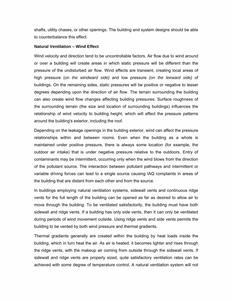
In buildings employing natural ventilation systems, sidewall vents and continuous ridge
vents for the full length of the building can be opened as far as desired to allow air to
move through the building. To be ventilated satisfactorily, the building must have both
sidewall and ridge vents. If a building has only side vents, then it can only be ventilated
during periods of wind movement outside. Using ridge vents and side vents permits the
building to be vented by both wind pressure and thermal gradients.
Thermal gradients generally are created within the building by heat loads inside the
building, which in turn heat the air. As air is heated, it becomes lighter and rises through
the ridge vents, with the makeup air coming from outside through the sidewall vents. If
sidewall and ridge vents are properly sized, quite satisfactory ventilation rates can be
achieved with some degree of temperature control. A natural ventilation system will not
be as dependable or satisfactory as a mechanical ventilation system in terms of
providing continuous uniform ventilation.
Natural ventilation and infiltration rates are governed by wind pressure on the building
and by internal temperature differences which create an upward movement of warm,
buoyant air. Natural ventilation will vary according to the weather conditions, and the
ventilation rates are not always predictable or reliable. Natural ventilation may fail
altogether in unfavorable conditions of wind and weather, and thus cannot be regarded
as a suitable method for all applications.
Natural Ventilation Guidelines
Several general guidelines should be followed when designing for natural ventilation:
1. In hot, humid climates, maximize air velocities in the occupied zones for bodily
cooling. In hot, arid climates, maximize air flow throughout the building for
structural cooling, particularly at night when temperatures are low.
2. Take advantage of topography, landscaping, and surrounding buildings to
redirect airflow and give maximum exposure to breezes. Use vegetation to funnel
breezes and avoid wind dams that reduce the driving pressure differential around
the building. Site objects should not obstruct inlet openings.
3. The stack effect requires vertical distances between openings to take advantage
of the effect; the greater the vertical distance, the greater the ventilation.
4. Openings with areas much larger than calculated are sometimes desirable when
anticipating increased occupancy or very hot weather.
5. Horizontal windows are generally better than square or vertical windows. They
produce more airflow over a wider range of wind directions and are most
beneficial in locations where prevailing wind patterns shift.
6. Window openings should be accessible to and operable by occupants. Vertical
air shafts or open staircases can be used to increase and take advantage of
stack effects. However, enclosed staircases intended for evacuation during a fire
should not be used for ventilation.
_____________________________________________________________________
SECTION -3 VENTILATION STRATEGIES FOR INDOOR AIR QUALITY
Indoor air quality (IAQ) refers to the quality of air within a space while ventilation is the
method of diluting indoor air with air from outdoors. Ventilation is a key principle of
improving IAQ. This approach can be effective either where buildings are under
ventilation or where a specific contaminant source cannot be identified. Ventilation can
be used to control indoor air contaminants by:
1. Diluting contaminants with outdoor air
a. Increase the total quantity of supply air (including outdoor air)
b. Increase the proportion of outdoor air to total air
c. Improve air distribution
2. Isolating or removing contaminants by controlling air pressure
relationships
a. Install effective local exhaust at the location of the source
b. Avoid recirculation of air that contains contaminants
c. Locate occupants near supply diffusers and sources near exhaust registers
d. Use air-tightening techniques to maintain pressure differentials and eliminate
pollutant pathways
e. Make sure that doors are closed where necessary to separate zones
Diluting contaminants with outdoor air
One of the most effective techniques for controlling contaminants, particularly odors, is
to dilute them by increasing the flow of outdoor air. This can be accomplished by
increasing the total supply airflow in the complaint area (e.g., opening supply diffusers,
adjusting dampers, etc), or at the air handling unit (e.g., cleaning the filter on the supply
fan). An alternative is to increase the proportion of outdoor air (e.g., adjusting the
outdoor air intake damper, installing minimum stops on variable air volume (VAV) boxes
so that they satisfy the outdoor air requirements of 20 cfm per person in accordance to
ASHRAE 62-1989, etc).
Besides inadequate quantities of outdoor air most ventilation deficiencies appear to be
linked to improper air distribution which can also produce IAQ problems. Positions of
inlet and extracts are most important and care should be taken in their location. Care
should be given to relatively nearby buildings and any contaminant discharges from
those buildings. Inlets should not be positioned near to any flue outlets, dry cleaning or
washing machine extraction outlets, kitchens, WC’s, etc. Diffusers should be properly
selected, located, installed, and maintained so that supply air is evenly distributed and
blended thoroughly with room air in the breathing zone. Short-circuiting occurs when
clean supply air is drawn into the return air plenum before it has mixed with the dirtier
room air, and therefore fails to dilute contaminants. Mixing problems can be aggravated
by temperature stratification. Stratification can occur, for example, in a space with high
ceilings in which ceiling-mounted supply diffusers distribute heated air.
Note the side effects of increased ventilation:
1. Mitigation by increasing the circulation of outdoor air requires good outdoor air
quality.
2. Increased supply air at the problem location might mean less supply air in other
areas.
3. Increased total air in the system and increased outdoor air will both tend to
increase energy consumption and may require increased equipment capacity.
4. Any approach which affects airflow in the building can change pressure
differences between rooms (or zones) and between indoors and outdoors. Also,
it might lead to increased infiltration of unconditioned outdoor air.
5. Increasing air in a VAV system may overcool an area to the extent that terminal
reheat units are needed.
Note: Because of the high ventilation rates, the cost of conditioning outdoor air goes up
significantly. Increasing a building’s ventilation rate to speed up the removal of localized
air-borne contaminants, even when energy use is not a concern, is not a solution to
every problem. The most efficient strategy to improve air quality is to remove the
contaminants at the source by local exhaust and then to rely on ventilation for the rest of
the building. In the case of an identifiable contaminant source, such as laboratory
equipment, the exhaust from the source should be connected directly to the outside.
The designer may wish to give consideration to the conditioning of indoor air with odor
removing equipment as an alternative to ventilation with outdoor air. This can take a
number of forms; the one most widely applied to building air conditioning being
adsorption by activated charcoal. This material is supplied in pellet form and applied as a
bed through which the air stream passes. Performance can be varied through the design
of the bed and the selection of the material. When the charcoal has adsorbed its full
capacity of odorants, it is usually returned to the manufacturer for regeneration and
replaced with fresh charcoal. The design of such a system would normally be based on
established requirements for outdoor air. For example, if outdoor air requirements for
odor control amount to 20 percent of the air being circulated, processing all of the
circulating indoor air with an odor controlling device that is 20 percent effective would
give comparable results. Outdoor air would, however, normally be required in sufficient
quantity to maintain CO2 levels within acceptable limits. In unusual situations where
outdoor air is not available, such as in submarines, the CO2 levels can be controlled by
chemical treatment.
Isolating or removing contaminants by controlling air pressure relationships
A variety of airborne particles, such as dust, smoke, pollens and organisms, are
contained in the outdoor air and are brought indoors along with the ventilation air. Lot of
contaminants are generated indoors by the activities of the occupants. If the contaminant
source has been identified, the “Isolation or Removal” can be more effective than
“Dilution”. The term “ventilation efficiency” is used to describe the ability of the ventilation
system to distribute supply air and remove internally generated pollutants. Researchers
are currently studying ways to measure ventilation efficiency and interpret the results of
those measurements.
Limiting the concentrations of contaminants could use any of the following techniques
depending on the nature and severity of the contaminant:
1) The first technique for isolating odors and contaminants is to design and operate the
HVAC system so that pressure relationships between rooms are controlled. This
control is accomplished by adjusting the air quantities that are supplied to and
removed from each room.
If more air is supplied to a room than is exhausted, the excess air leaks out of the
space and the room is said to be under positive pressure. If less air is supplied than
is exhausted, air is pulled into the space and the room is said to be under negative
pressure.
Control of pressure relationships is critically important in mixed use buildings or
buildings with special use areas. Lobbies and buildings in general are often designed
to operate under positive pressure to prevent or minimize the infiltration of
unconditioned air, with its potential to cause drafts and introduce dust, dirt, and
thermal discomfort. Without proper operation and maintenance, these pressure
differences are not likely to remain as originally designed.
2) The second technique is to use local exhaust systems (sometimes known as
dedicated exhaust ventilation systems) to isolate and remove contaminants by
maintaining negative pressure in the area around the contaminant source. It also
dilutes the contaminant by drawing cleaner air from surrounding areas into the
exhaust airstream.
Local exhaust can be linked to the operation of a particular piece of equipment (such
as a kitchen range) or used to treat an entire room (such as a smoking lounge or
custodial closet). Air should be exhausted to the outdoors and not recirculated from
locations which produce significant odors and high concentrations of contaminants
(such as copy rooms, bathrooms, kitchens and beauty salons).
Spaces where local exhaust is used must be provided with make-up air and the local
exhaust must function in coordination with the rest of the ventilation system. Under
some circumstances, it may be acceptable to transfer conditioned air from relatively
clean parts of a building to comparatively dirty areas and use it as make-up air for a
local exhaust system. It may be necessary to add door or wall louvers in order to
provide a path for the make-up air. (Make sure that this action does not violate fire
codes.) Such a transfer can achieve significant energy savings.
Correct identification of the pollutant source and installation of the local exhaust is
critically important. For example, an improperly designed local exhaust can draw
other contaminants through the occupied space and make the problem worse.
The physical layout of grilles and diffusers relative to room occupants and pollutant
sources can be important. If supply diffusers are all at one end of a room and returns
are all at the other end, the people located near the supplies may be provided with
relatively clean air while those located near the returns breathe air that has already
picked up contaminants from all the sources in the room that are not served by local
exhaust.
3) The third technique is to use HVAC designs that introduce 100% outdoor air or that
simply transfer air within the building. In hospitals for instance, where the control of
infection from airborne sources is of special importance, ventilation is used to provide
positive pressures in spaces containing patients prone to infection, and negative
pressures in spaces containing patients with highly communicable diseases. It is
common practice also to circulate a high proportion of outdoor air, up to 100 percent,
in areas such as operating rooms. This results in a particularly high heating and
cooling load for ventilation and leads designers to consider the economics of heat
recovery devices in the exhaust air.
Air Quality Control
Most indoor air pollution problems can be lessened or solved by increased air mixing or
ventilation, by eliminating indoor sources and adjusting odorous activities, or by cleaning
recirculated air. There is no easy way to find the best mix. The foremost consideration in
all buildings is to provide adequate transfer of oxygen and metabolic products.
In public places, like shopping malls, theaters, court rooms, etc. the primary concern is
the adequate ingress of outside air based on the occupancy levels. A person, when
seated, usually inhales about 18 cu ft of air per hr. The exhaled air contains about 16
percent O2 and about 4 percent CO2. Thus, if only 18 cu ft per hr of fresh air were
provided for each person in a continuously occupied space, the concentrations of CO2
would exceed the permissible levels. (ASHARE recommends the CO2 levels should not
exceed 1000 ppm). Consumption of O2 and production of CO2 increase with activity, and
ventilation requirements increase correspondingly. For people who are standing, the
values are about 50 percent higher than for those seated. Therefore, supplies of outside
air in excess of that required for controlling the effect of respiration on O2 and CO2
levels, plus for pressurization of the building, are required. The building needs to be
positive pressurized so that uncontrolled infiltration is prevented.
In residential buildings, the main problem is humidity control. In reality, the water is
produced during the two short meal time and bathing peaks; and instead of vanishing
slowly, it migrates to cold spots where it condenses and remains stubbornly hidden in
the form of moisture in the building materials, while most of the indoor air rapidly
becomes normal or dry.
Condensation is a very serious problem if buildings designed for freely flowing air are
suddenly retrofitted with insulation or vapor barriers to reduce heating costs. This
condensation threatens the health of both the basic building structure and the
occupants. The only adequate solution is to 'seal' the building and to provide intentional
forced or natural ventilation at a rate adequate to mix air fully and remove excess
moisture. Furthermore, buildings that rely on mechanical ventilation should not rely on
uncontrolled infiltration, but should provide either natural cross-draught ventilation or
forced air circulation or both. Further, it is vital that such buildings have an appropriately
placed air intake through which air may be admitted, either continually or in batches, as
desired. In any case, natural ventilation should always be provided.
Natural forces exert an important influence on air movement between zones and
between the buildings’s interior and exterior. Both the stack effect and wind can
overpower a building’s mechanical system and disrupt air circulation and ventilation,
especially if the building envelope is leaky.
Air-Cleaning
The third IAQ control strategy is to clean the air. Air cleaning is usually most effective
when used in conjunction with either source control or ventilation; however, it may be the
only approach when the source of pollution is outside of the building. Efficient air
filtration prevents fouling of the system and is of special importance in urban areas,
where damage is likely to be caused to decorations and fittings by discoloration owing to
airborne dust particles. In order to obtain maximum filtration efficiency with the minimum
capital and maintenance expenditure, the utmost care should be given to the location of
the air intake in relation to the prevailing wind, the position of chimneys and the relative
atmospheric dust concentration in the environs of the building.
Airborne dust and dirt can be generated within the building from the personnel and their
movements, as well as by machines, such as those used for card sorting. The degree of
filtration necessary will depend on the use of the building or the conditioned space. The
choice of filtration systems will depend on the degree of contamination of the air and on
the cleanliness required. A combination of filter types may well give the best service and
minimum operation costs. There are four technologies that remove contaminants from
the air:
1. Particulate filtration
2. Electrostatic precipitation
3. Negative ion generation
4. Gas sorption
The first three approaches are designed to remove particulates, while the fourth is
designed to remove gases.
Particulate filtration:
Particulate Filtration removes suspended liquid or solid materials whose size, shape and
mass allow them to remain airborne for the air velocity conditions present. Filters are
available in a range of efficiencies, with higher efficiency indicating removal of a greater
proportion of particles and of smaller particles. Moving to medium efficiency, pleated
filters are advisable to improve IAQ and increase protection for equipment. However, the
higher the efficiency of the filter, the more it will increase the pressure drop within the air
distribution system and reduce total airflow (unless other adjustments are made to
compensate). It is important to select an appropriate filter for the specific application and
to make sure that the HVAC system will continue to perform as designed. Filters are
rated by different standards (e.g., arrestance and dust spot) which measure different
aspects of performance. The HEPA (high efficiency particulate air) filters are
recommended for maintaining absolutely clean environments.
Electrostatic Precipitation:
Electrostatic Precipitation is another type of particulate control. It uses the attraction of
charged particles to oppositely-charged surfaces to collect airborne particulates. In this
process, the particles are charged by ionizing the air with an electric field. The charged
particles are then collected by a strong electric field generated between oppositely-
charged electrodes. This provides relatively high efficiency filtration of small respirable
particles at low air pressure losses.
Electrostatic precipitators may be installed in air distribution equipment or in specific
usage areas. As with other filters, they must be serviced regularly. Note, however, that
electrostatic precipitators produce some ozone. Because ozone is harmful at elevated
levels, EPA has set standards for ozone concentrations in outdoor air, and NIOSH and
OSHA have established guidelines and standards, respectively, for ozone in indoor air.
The amount of ozone emitted from electrostatic precipitators varies from model to model.
Negative ion generators:
Negative ion generators use static charges to remove particles from the indoor air. When
the particles become charged, they are attracted to surfaces such as walls, floors, table
tops, draperies, and occupants. Some designs include collectors to attract the charged
particles back to the unit.
Negative ion generators are not available for installation in ductwork, but are sold as
portable or ceiling-mounted units. As with electrostatic precipitators, negative ion
generators may produce ozone, either intentionally or as a by-product of use.
Gas sorption:
Fumes and smells can be removed from air by chemical processes such as “gas
sorption” which control compounds that behave as gases rather than as particles (e.g.,
gaseous contaminants such as formaldehyde, sulfur dioxide, ozone, and oxides of
nitrogen). These may be essential when the ambient air is heavily polluted, although it
may be possible to limit operating costs by minimizing the thermal loads caused by the
introduction of large quantities of fresh air. The decision to use odor removing equipment
will normally be made on economic grounds, but the arguments in its favor will be
increased by the currently rising cost of energy. Once this equipment is installed, it
should be regularly serviced to ensure satisfactory performance.
Gas sorption involves one or more of the following processes with the sorption material
(e.g., activated carbon, chemically treated active clays):
1. A chemical reaction between the pollutant and the sorbent,
2. A binding of the pollutant and the sorbent, or
3. Diffusion of the contaminant from areas of higher concentration to areas of lower
concentration.
Gas sorption units are installed as part of the air distribution system. Each type of
sorption material performs differently with different gases. Gas sorption is not effective
for removing carbon monoxide. There are no standards for rating the performance of
gaseous air cleaners, making the design and evaluation of such systems problematic.
Operating expenses of these units can be quite high, and the units may not be effective
if there is a strong source nearby.
Use of carbon dioxide sensors for demand control ventilation:
Carbon dioxide-based demand-controlled ventilation systems vary the ventilation rate
based on carbon dioxide (CO2) levels in the building. For spaces with extreme variations
in occupancy, such as banquet halls or meeting rooms, carbon dioxide sensors located
in each zone adjacent to the room thermostat or in the common return air automatically
control the amount of outside air. The controls are set such that the CO2 levels do not
exceed ASHRAE permissible levels of 1000ppm.
The equation for calculating outdoor quantities using carbon dioxide measurements is:
Where:
• Cs = ppm of carbon dioxide in the mixed air (if measured at an air handler) or in
supply air (if measured in a room)
• Cr = ppm of carbon dioxide in the return air
• Co = ppm of carbon dioxide in the outdoor air
The auto-controller ensures that the increased ventilation is supplied only when required
or needed for higher occupancies. This is a benefit in terms of energy cost savings
because of reduced cooling and heating of outdoor air during reduced occupancy rates.
Building Pressurization
A common cause of IAQ problems in hot and humid climates is negative building
pressure. Negative building pressure can occur through the improper design and
operation of the exhaust systems in a building. Operating exhaust fans without the
outside air being compensated through the air-handling system will result in negative
pressure in the building. Negative pressure in a building allows uncontrolled infiltration
through doors and the exterior envelope of the building. This will typically make the
building feel drafty and difficult to heat in cold climates and muggy or musty in hot and
humid climates, since unconditioned outside air is being constantly introduced into the
building through uncontrolled infiltration.
The basic principle of air movement from areas of relatively higher pressure to areas of
relatively lower pressure can produce many patterns of contaminant distribution,
including:
1. Local circulation in the room containing the pollutant source
2. Air movement into adjacent spaces that are under lower pressure (Note: even if
two rooms are both under positive pressure compared to the outdoors, one room
is usually at a lower pressure than the other)
3. Recirculation of air within the zone containing the pollutant source or in adjacent
zones where return systems overlap
4. Movement from lower to upper levels of the building
5. Air movement into the building through either infiltration of outdoor air or re-entry
of exhaust air
The HVAC system is generally the predominant pathway and driving force for air
movement and distribution of contaminants. The large buildings are divided into multiple
zones each having independent HVAC system or control. But still the contaminants can
flow from one zone to another because of building obstructions and people movement.
For example, as air moves from supply registers or diffusers to return air grilles, it is
diverted or obstructed by partitions, walls and furnishings, and redirected by openings
that provide pathways for air movement. On a localized basis, the movement of people
has a major impact on the movement of pollutants. Some of the pathways change as
doors and windows open and close. It is useful to think of the entire building — the
rooms and the connections (e.g., chases, corridors, stairways, elevator shafts) between
them — as part of the air distribution system. Air moves from areas of higher pressure to
areas of lower pressure through any available opening. A small crack or hole can admit
significant amounts of air if the pressure differentials are high enough (which may be
very difficult to assess). Theoretically, one-inch water gauge pressure is equivalent to
wind velocity of 4005 feet per minute (~45 miles/hr). The amount of expected leakage
can be calculated from the following:
Leakage in CFM = x 4005
Assuming 0.05” wg,
Leakage = 0.223 x 4005
= 895 feet per minute
With a total of ½ square feet opening size:
Leakage = ½ x 895 = ~450 CFM
With higher pressurization, the leakage velocity, leakage rates and processing costs
shall also increase. The room pressure should be limited to 0.03” to 0.05” (~0.75 to 1.25
mm) as pressure above this, not only entails high capital costs but also increases the
operating costs.
Positive pressurization can be maintained only if the sealing integrity of the building is
maintained. The building should be air tight for low air leakage performance. There are
areas within the facility that require negative exhausts such as toilets, pantry, laboratory
or battery room but these are controlled ventilation areas having fixed amount of
exhaust. Uncontrolled leakage areas in the building are door undercuts; walls, ceilings
and duct joints; etc, that should be restricted as far as possible. Remember a slogan;
“Build tight – ventilate right”
The building shall be optimally pressurized to achieve low capital costs, overall energy
conservation and treatment costs on filtration.
______________________________________________________________________
SECTION -4: ESTIMATING VENTILATION RATES
To satisfy the ventilation requirement a mechanical ventilation system should be capable
of delivering the design ventilation rate. The ventilation rate can be estimated using
various techniques:
Air Quality Method
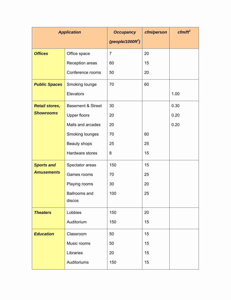
ASHRAE Standard 62-1999: “Ventilation for Acceptable Indoor Air Quality” is a
nationally accepted standard that provides acceptable ventilation rates per person and is
related to the occupational density and activity within the space. The table below
provides a snapshot of the outside air recommendations, and the procedure is as
follows:
1) Determine the number of people occupying the respective building spaces; People =
Occupancy/1000 x Floor Area (ft2)
2) Find the Ventilation Rates for Acceptable Indoor Air Quality: Q = (cfm outdoor air
person) * (number of people)
Q is the desired flow rate. The “cfm outdoor air person” represents ASHRAE's
recommended design outdoor airflow rate. (Refer to the table below.)
Alternatively, the ventilation rate can be estimated directly based on the sq-ft area:
Q = (cfm/sq-ft floor area) * (sq-ft floor area)
The “cfm/sq-ft floor area” represents ASHRAE's recommended design values.
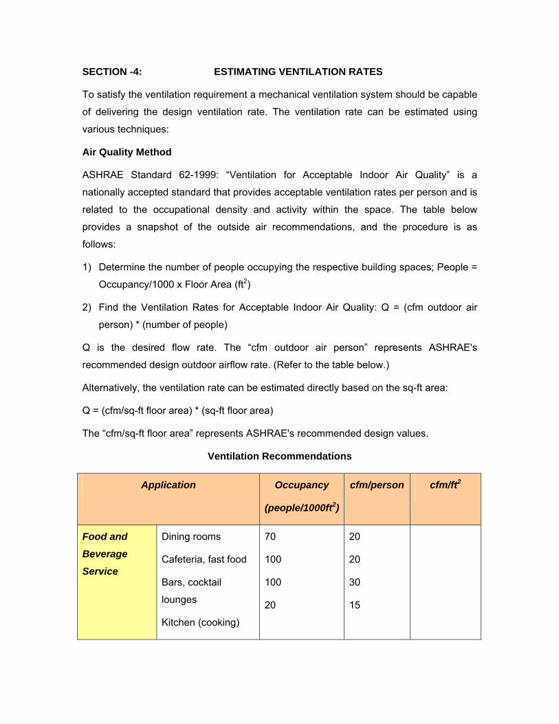
Ventilation Recommendations
Application Occupancy
(people/1000ft2)
cfm/person cfm/ft2
Food and
Beverage
Service
Dining rooms
Cafeteria, fast food
Bars, cocktail
lounges
Kitchen (cooking)
70
100
100
20
20
20
30
15
Application Occupancy
(people/1000ft2)
cfm/person cfm/ft2
Offices Office space
Reception areas
Conference rooms
7
60
50
20
15
20
Public Spaces Smoking lounge
Elevators
70 60
1.00
Retail stores,
Showrooms
Basement & Street
Upper floors
Malls and arcades
Smoking lounges
Beauty shops
Hardware stores
30
20
20
70
25
8
60
25
15
0.30
0.20
0.20
Sports and
Amusements
Spectator areas
Games rooms
Playing rooms
Ballrooms and
discos
150
70
30
100
15
25
20
25
Theaters Lobbies
Auditorium
150
150
20
15
Education Classroom
Music rooms
Libraries
Auditoriums
50
50
20
150
15
15
15
15
Application Occupancy
(people/1000ft2)
cfm/person cfm/ft2
Hotels, Motels
Resorts,
Dormitories
Bedrooms
Living rooms
Lobbies
Conference rooms
Assembly rooms
Dry cleaning,
laundry
Gambling casinos
30
50
120
30
120
15
20
15
30
30
30 cfm/room
30 cfm/room
Health Care
Facilities
Hospital operating
rooms
Hospital patient
rooms
Laboratories
Medical procedure
rooms
Pharmacies
Physical therapy
20
10
30
20
20
20
30
25
20
15
15
15
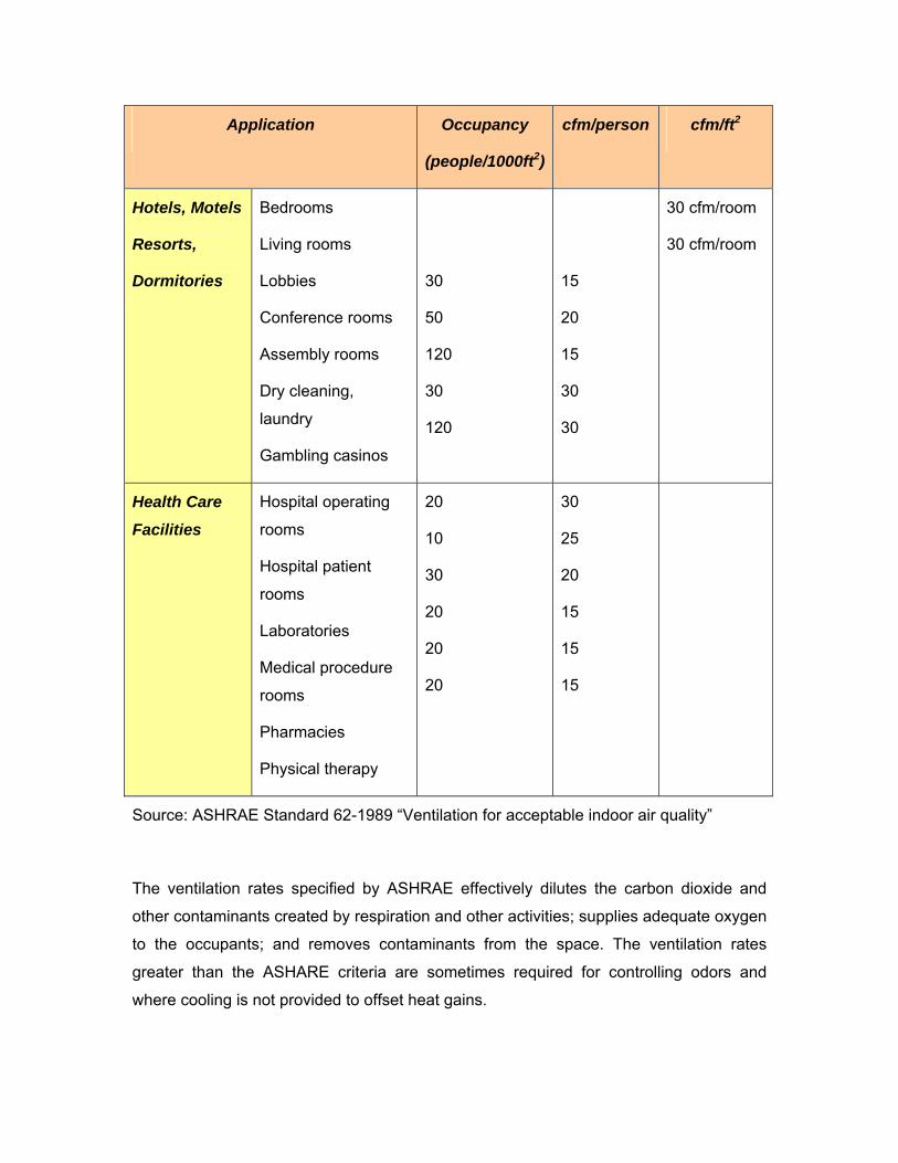
Source: ASHRAE Standard 62-1989 “Ventilation for acceptable indoor air quality”
The ventilation rates specified by ASHRAE effectively dilutes the carbon dioxide and
other contaminants created by respiration and other activities; supplies adequate oxygen
to the occupants; and removes contaminants from the space. The ventilation rates
greater than the ASHARE criteria are sometimes required for controlling odors and
where cooling is not provided to offset heat gains.
Air Change Method
The most common method used to calculate ventilation air requirements is based on
complete changes of air in a structure or room in a given time period. To determine the
airflow required to adequately ventilate an area,
1) Calculate the Room Volume to be ventilated: Width x Length x Height = ft3 (cubic
feet), then
2) Calculate the Air Volume requirement by multiplying the Room Volume by the Air
Change Rate per hour = ft3/h.
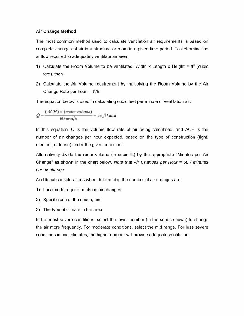
The equation below is used in calculating cubic feet per minute of ventilation air.
In this equation, Q is the volume flow rate of air being calculated, and ACH is the
number of air changes per hour expected, based on the type of construction (tight,
medium, or loose) under the given conditions.
Alternatively divide the room volume (in cubic ft.) by the appropriate "Minutes per Air
Change" as shown in the chart below. Note that Air Changes per Hour = 60 / minutes
per air change
Additional considerations when determining the number of air changes are:
1) Local code requirements on air changes,
2) Specific use of the space, and
3) The type of climate in the area.
In the most severe conditions, select the lower number (in the series shown) to change
the air more frequently. For moderate conditions, select the mid range. For less severe
conditions in cool climates, the higher number will provide adequate ventilation.
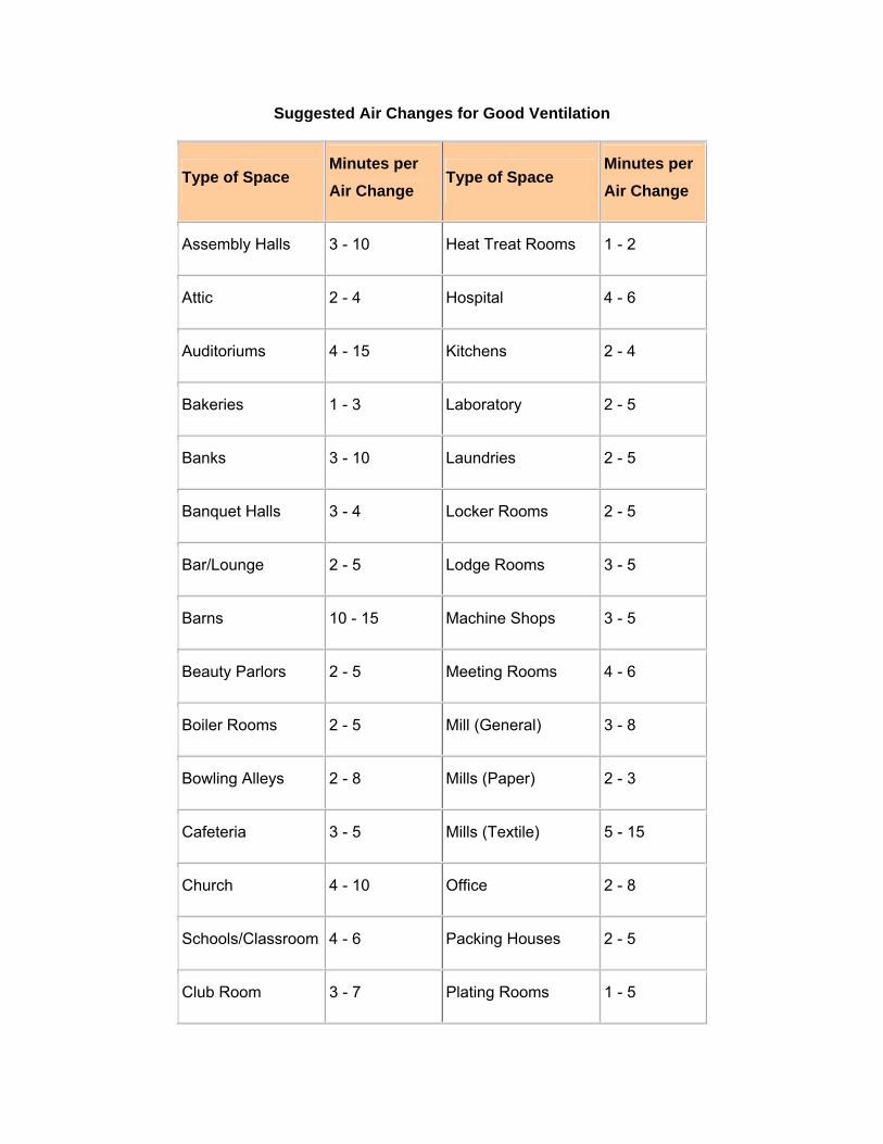
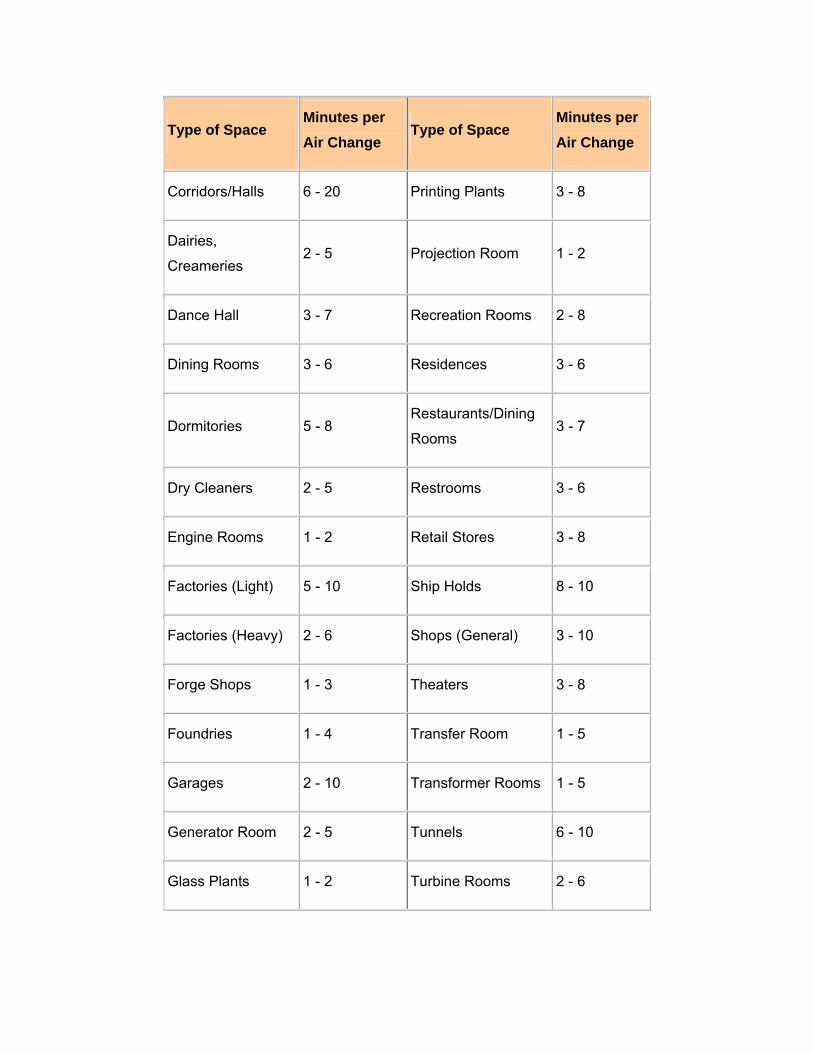
Suggested Air Changes for Good Ventilation
Type of Space Minutes per Air Change
Type of Space Minutes per Air Change
Assembly Halls 3 - 10 Heat Treat Rooms 1 - 2
Attic 2 - 4 Hospital 4 - 6
Auditoriums 4 - 15 Kitchens 2 - 4
Bakeries 1 - 3 Laboratory 2 - 5
Banks 3 - 10 Laundries 2 - 5
Banquet Halls 3 - 4 Locker Rooms 2 - 5
Bar/Lounge 2 - 5 Lodge Rooms 3 - 5
Barns 10 - 15 Machine Shops 3 - 5
Beauty Parlors 2 - 5 Meeting Rooms 4 - 6
Boiler Rooms 2 - 5 Mill (General) 3 - 8
Bowling Alleys 2 - 8 Mills (Paper) 2 - 3
Cafeteria 3 - 5 Mills (Textile) 5 - 15
Church 4 - 10 Office 2 - 8
Schools/Classroom 4 - 6 Packing Houses 2 - 5
Club Room 3 - 7 Plating Rooms 1 - 5
Type of Space Minutes per Air Change
Type of Space Minutes per Air Change
Corridors/Halls 6 - 20 Printing Plants 3 - 8
Dairies,
Creameries 2 - 5 Projection Room 1 - 2
Dance Hall 3 - 7 Recreation Rooms 2 - 8
Dining Rooms 3 - 6 Residences 3 - 6
Dormitories 5 - 8 Restaurants/Dining
Rooms 3 - 7
Dry Cleaners 2 - 5 Restrooms 3 - 6
Engine Rooms 1 - 2 Retail Stores 3 - 8
Factories (Light) 5 - 10 Ship Holds 8 - 10
Factories (Heavy) 2 - 6 Shops (General) 3 - 10
Forge Shops 1 - 3 Theaters 3 - 8
Foundries 1 - 4 Transfer Room 1 - 5
Garages 2 - 10 Transformer Rooms 1 - 5
Generator Room 2 - 5 Tunnels 6 - 10
Glass Plants 1 - 2 Turbine Rooms 2 - 6
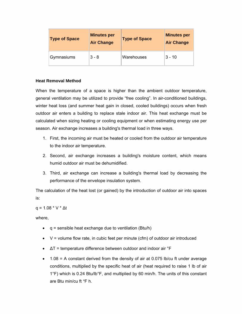
Type of Space Minutes per Air Change
Type of Space Minutes per Air Change
Gymnasiums 3 - 8 Warehouses 3 - 10
Heat Removal Method
When the temperature of a space is higher than the ambient outdoor temperature,
general ventilation may be utilized to provide “free cooling”. In air-conditioned buildings,
winter heat loss (and summer heat gain in closed, cooled buildings) occurs when fresh
outdoor air enters a building to replace stale indoor air. This heat exchange must be
calculated when sizing heating or cooling equipment or when estimating energy use per
season. Air exchange increases a building's thermal load in three ways.
1. First, the incoming air must be heated or cooled from the outdoor air temperature
to the indoor air temperature.
2. Second, air exchange increases a building's moisture content, which means
humid outdoor air must be dehumidified.
3. Third, air exchange can increase a building's thermal load by decreasing the
performance of the envelope insulation system.
The calculation of the heat lost (or gained) by the introduction of outdoor air into spaces
is:
q = 1.08 * V * ∆t
where,
• q = sensible heat exchange due to ventilation (Btu/h)
• V = volume flow rate, in cubic feet per minute (cfm) of outdoor air introduced
• ∆T = temperature difference between outdoor and indoor air °F
• 1.08 = A constant derived from the density of air at 0.075 lb/cu ft under average
conditions, multiplied by the specific heat of air (heat required to raise 1 lb of air
1°F) which is 0.24 Btu/lb°F, and multiplied by 60 min/h. The units of this constant
are Btu min/cu ft °F h.
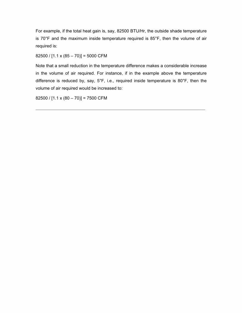
For example, if the total heat gain is, say, 82500 BTU/Hr, the outside shade temperature
is 70°F and the maximum inside temperature required is 85°F, then the volume of air
required is:
82500 / [1.1 x (85 – 70)] = 5000 CFM
Note that a small reduction in the temperature difference makes a considerable increase
in the volume of air required. For instance, if in the example above the temperature
difference is reduced by, say, 5°F, i.e., required inside temperature is 80°F, then the
volume of air required would be increased to:
82500 / [1.1 x (80 – 70)] = 7500 CFM
______________________________________________________________________
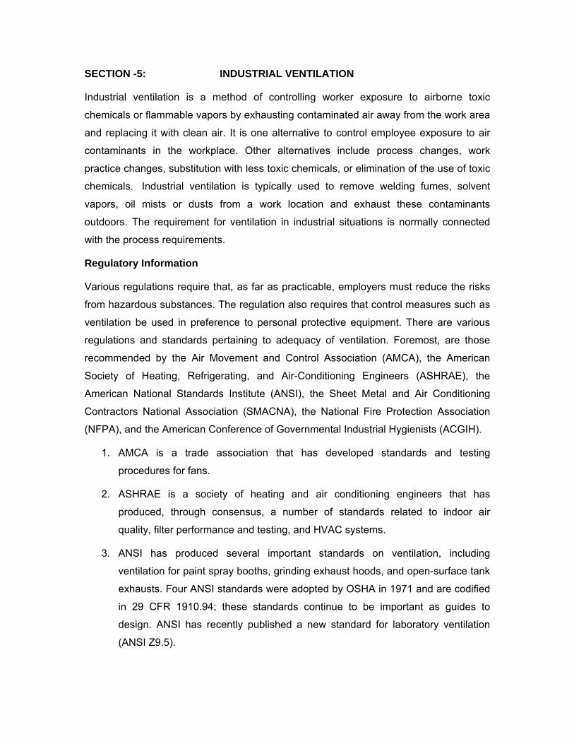
SECTION -5: INDUSTRIAL VENTILATION
Industrial ventilation is a method of controlling worker exposure to airborne toxic
chemicals or flammable vapors by exhausting contaminated air away from the work area
and replacing it with clean air. It is one alternative to control employee exposure to air
contaminants in the workplace. Other alternatives include process changes, work
practice changes, substitution with less toxic chemicals, or elimination of the use of toxic
chemicals. Industrial ventilation is typically used to remove welding fumes, solvent
vapors, oil mists or dusts from a work location and exhaust these contaminants
outdoors. The requirement for ventilation in industrial situations is normally connected
with the process requirements.
Regulatory Information
Various regulations require that, as far as practicable, employers must reduce the risks
from hazardous substances. The regulation also requires that control measures such as
ventilation be used in preference to personal protective equipment. There are various
regulations and standards pertaining to adequacy of ventilation. Foremost, are those
recommended by the Air Movement and Control Association (AMCA), the American
Society of Heating, Refrigerating, and Air-Conditioning Engineers (ASHRAE), the
American National Standards Institute (ANSI), the Sheet Metal and Air Conditioning
Contractors National Association (SMACNA), the National Fire Protection Association
(NFPA), and the American Conference of Governmental Industrial Hygienists (ACGIH).
1. AMCA is a trade association that has developed standards and testing
procedures for fans.
2. ASHRAE is a society of heating and air conditioning engineers that has
produced, through consensus, a number of standards related to indoor air
quality, filter performance and testing, and HVAC systems.
3. ANSI has produced several important standards on ventilation, including
ventilation for paint spray booths, grinding exhaust hoods, and open-surface tank
exhausts. Four ANSI standards were adopted by OSHA in 1971 and are codified
in 29 CFR 1910.94; these standards continue to be important as guides to
design. ANSI has recently published a new standard for laboratory ventilation
(ANSI Z9.5).
4. SMACNA is an association representing sheet metal contractors and suppliers. It
sets standards for ducts and duct installation.
5. NFPA has produced a number of recommendations (which become requirements
when adopted by local fire agencies), e.g., NFPA 45 lists a number of ventilation
requirements for laboratory fume hood use.
6. The ACGIH has published widely used guidelines for industrial ventilation.
7. OSHA Ventilation criteria or standards are included in the OSHA regulatory
codes for job- or task-specific worker protection. In addition, many OSHA health
standards include ventilation requirements. The four standards in 29 CFR
1910.94 deal with local exhaust systems, and OSHA's construction standards (29
CFR 1926) contain ventilation standards for welding. OSHA's compliance policy
regarding violation of ventilation standards is set forth in the Field Inspection
Reference Manual.
The ventilation system should comply with the requirements laid down in the current
statutory legislation or any revisions currently in force, and consideration should also be
given to any relevant insurance company requirements.
Exhaust Ventilation System
Exhaust ventilation systems are used to remove airborne contaminants consisting of
dusts, fumes, mists, fibers, vapors, and gases that can create an unsafe, unhealthy, or
undesirable atmosphere. Replacement air, which is usually filtered and/or conditioned,
provides air to the work space, which replaces exhausted air. A complete industrial
ventilation program includes replacement air systems that provide a total volumetric flow
rate equal to the total exhaust rate. If insufficient replacement air is provided, the
pressure of the building will be negative relative to local atmospheric pressure. Negative
pressure allows air to infiltrate through open doors, window cracks, and combustion
equipment vents.
There are two types of exhaust systems:
1. A general exhaust or dilution system in which an entire work space is exhausted
without considering specific operations.
2. A local exhaust in which the contaminant is controlled at its source.
3.
General Exhaust (or Dilution) Ventilation System
The terms “general exhaust” and “dilution ventilation” are often used interchangeably.
This type of exhaust refers to dilution of contaminated air in a general area, room, or
building and is usually accomplished with the use of large exhaust fans in the walls or
roof of a building or room. Opening doors or windows can be used as dilution ventilation,
but this is not always a reliable method since air movement is not controlled. Cooling
fans (floor fans) are also sometimes used as a method of ventilation, but these fans
usually just blow the contaminant around the work area without effectively controlling it.
In general, dilution ventilation is not as satisfactory for health hazard control as is local
exhaust. In some cases, dilution ventilation must be used because the operation or
process prohibits local exhaust. Circumstances may be found in which dilution
ventilation provides an adequate amount of control more economically than a local
exhaust system. Economical considerations should not be based entirely upon the first
cost of the system because dilution ventilation frequently exhausts large volumes of heat
from a building and can easily be a troublesome factor.
General exhaust ventilation (dilution ventilation) is appropriate when:
1. Emission sources contain materials of relatively low hazard. (The degree of
hazard is related to toxicity, dose rate, and individual susceptibility);
2. Emission sources are primarily vapors or gases, or small, respirable-size
aerosols (those not likely to settle);
3. Emissions occur uniformly;
4. Emissions are widely dispersed;
5. Moderate climatic conditions prevail;
6. Heat is to be removed from the space by flushing it with outside air;
7. Concentrations of vapors are to be reduced in an enclosure; and
8. Portable or mobile emission sources are to be controlled.
Local exhaust ventilating is appropriate when:
1. Emission sources contain materials of relatively high hazard;
2. Emitted materials are primarily larger-diameter particulates (likely to settle);
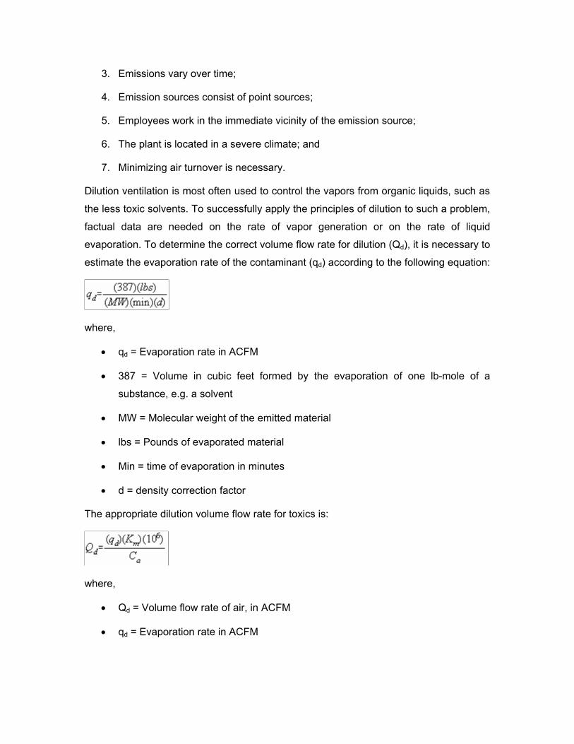
3. Emissions vary over time;
4. Emission sources consist of point sources;
5. Employees work in the immediate vicinity of the emission source;
6. The plant is located in a severe climate; and
7. Minimizing air turnover is necessary.
Dilution ventilation is most often used to control the vapors from organic liquids, such as
the less toxic solvents. To successfully apply the principles of dilution to such a problem,
factual data are needed on the rate of vapor generation or on the rate of liquid
evaporation. To determine the correct volume flow rate for dilution (Qd), it is necessary to
estimate the evaporation rate of the contaminant (qd) according to the following equation:
where,
• qd = Evaporation rate in ACFM
• 387 = Volume in cubic feet formed by the evaporation of one lb-mole of a
substance, e.g. a solvent
• MW = Molecular weight of the emitted material
• lbs = Pounds of evaporated material
• Min = time of evaporation in minutes
• d = density correction factor
The appropriate dilution volume flow rate for toxics is:
where,
• Qd = Volume flow rate of air, in ACFM
• qd = Evaporation rate in ACFM
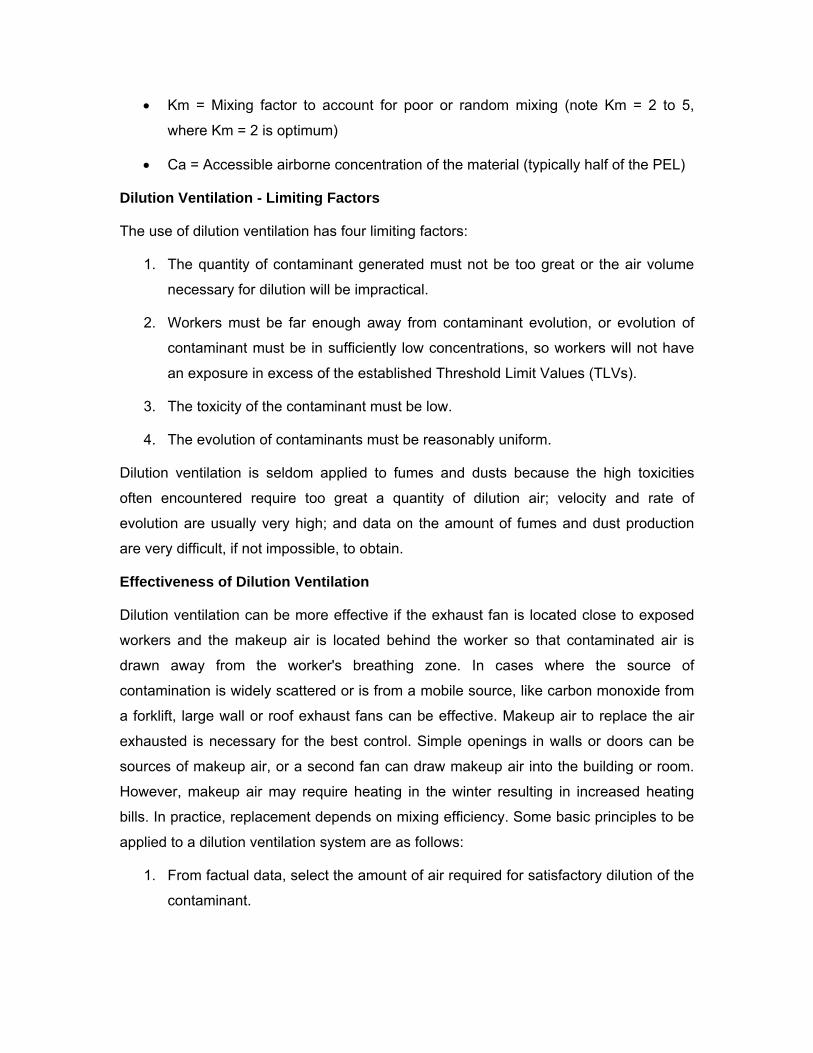
• Km = Mixing factor to account for poor or random mixing (note Km = 2 to 5,
where Km = 2 is optimum)
• Ca = Accessible airborne concentration of the material (typically half of the PEL)
Dilution Ventilation - Limiting Factors
The use of dilution ventilation has four limiting factors:
1. The quantity of contaminant generated must not be too great or the air volume
necessary for dilution will be impractical.
2. Workers must be far enough away from contaminant evolution, or evolution of
contaminant must be in sufficiently low concentrations, so workers will not have
an exposure in excess of the established Threshold Limit Values (TLVs).
3. The toxicity of the contaminant must be low.
4. The evolution of contaminants must be reasonably uniform.
Dilution ventilation is seldom applied to fumes and dusts because the high toxicities
often encountered require too great a quantity of dilution air; velocity and rate of
evolution are usually very high; and data on the amount of fumes and dust production
are very difficult, if not impossible, to obtain.
Effectiveness of Dilution Ventilation
Dilution ventilation can be more effective if the exhaust fan is located close to exposed
workers and the makeup air is located behind the worker so that contaminated air is
drawn away from the worker's breathing zone. In cases where the source of
contamination is widely scattered or is from a mobile source, like carbon monoxide from
a forklift, large wall or roof exhaust fans can be effective. Makeup air to replace the air
exhausted is necessary for the best control. Simple openings in walls or doors can be
sources of makeup air, or a second fan can draw makeup air into the building or room.
However, makeup air may require heating in the winter resulting in increased heating
bills. In practice, replacement depends on mixing efficiency. Some basic principles to be
applied to a dilution ventilation system are as follows:
1. From factual data, select the amount of air required for satisfactory dilution of the
contaminant.
2. Locate the exhaust openings near the sources of contaminant, if possible, in
order to obtain the benefit of spot ventilation.
3. For dilution methods to be effective, the exhaust outlet and air supply must be
located so that all the air used in the ventilation passes through the zone of
contamination.
4. Replace exhausted air by a make-up air system. Make-up air should be heated
during cold weather. Dilution ventilation systems usually handle large quantities
of air by means of propeller fans. Make-up air usually must be provided if the
ventilation is to be adequate and the system is to operate satisfactorily.
5. The general air movements in the room caused by suction at the exhaust
opening should keep the contaminated air between the operator and the exhaust
opening, and not draw contaminants across the operator.
6. A combined supply and exhaust system is preferred with a slight excess of
exhaust if there are adjoining occupied spaces, and a slight excess of supply if
there are no such spaces.
7. Avoid re-entrance of the exhausted air by discharging the exhaust high above the
roof line, or by assuring that no window, outside air intakes, or other such
openings are near the exhaust discharge.
Local Exhaust Ventilation Systems
Local exhaust ventilation captures air contaminants at their source.
Local exhaust ventilation, unlike dilution ventilation, is designed to capture an emitted
contaminant at or near its source before the contaminant has a chance to disperse into
the workplace air. Local exhaust ventilation operates on the principle that air moves from
an area of high pressure to an area of low pressure and the difference in pressure is
created by a fan that draws or sucks air through the ventilation system. A local exhaust
system operates in the same manner as a household vacuum cleaner.
Local exhaust ventilation is needed when employees are exposed to high toxicity
chemicals, when large amounts of dusts or welding fumes are generated, or when
increased heating costs from ventilation in cold weather are a concern. It is necessary
when:
1. the contaminant is toxic or corrosive (such as lead fumes, acid mist, solvent
vapor),
2. contaminant levels are high,
3. contaminants must be filtered out before release into the air, and
4. the process gives off heat.
It is most effective because:
1. it minimizes employee exposure to contaminants,
2. the volume of exhaust air is much less than for general ventilation,
3. the contaminant can be collected for disposal or recovery,
4. equipment in the workplace is protected from heat and corrosive substances, and
5. employees may not have to wear respiratory protection.
System Configuration
A typical local exhaust ventilation system is composed of five parts:
1. A fan that moves the air through the system and discharges it outdoors,
2. A "hood" or opening that captures the contaminant at the source,
3. Ducts that transport the airborne chemicals through the system,
4. An air cleaning device (not always required) that removes the contaminant from
the moving air in the system, and
5. An exhaust stack through which the contaminated air is discharged.
The figure below illustrates the basic components of a local exhaust system.
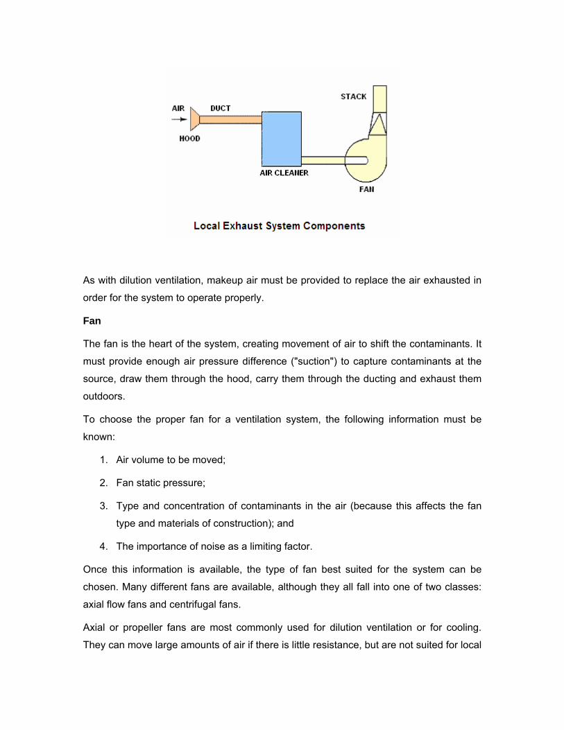
As with dilution ventilation, makeup air must be provided to replace the air exhausted in
order for the system to operate properly.
Fan
The fan is the heart of the system, creating movement of air to shift the contaminants. It
must provide enough air pressure difference ("suction") to capture contaminants at the
source, draw them through the hood, carry them through the ducting and exhaust them
outdoors.
To choose the proper fan for a ventilation system, the following information must be
known:
1. Air volume to be moved;
2. Fan static pressure;
3. Type and concentration of contaminants in the air (because this affects the fan
type and materials of construction); and
4. The importance of noise as a limiting factor.
Once this information is available, the type of fan best suited for the system can be
chosen. Many different fans are available, although they all fall into one of two classes:
axial flow fans and centrifugal fans.
Axial or propeller fans are most commonly used for dilution ventilation or for cooling.
They can move large amounts of air if there is little resistance, but are not suited for local
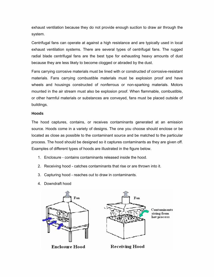
exhaust ventilation because they do not provide enough suction to draw air through the
system.
Centrifugal fans can operate at against a high resistance and are typically used in local
exhaust ventilation systems. There are several types of centrifugal fans. The rugged
radial blade centrifugal fans are the best type for exhausting heavy amounts of dust
because they are less likely to become clogged or abraded by the dust.
Fans carrying corrosive materials must be lined with or constructed of corrosive-resistant
materials. Fans carrying combustible materials must be explosion proof and have
wheels and housings constructed of nonferrous or non-sparking materials. Motors
mounted in the air stream must also be explosion proof. When flammable, combustible,
or other harmful materials or substances are conveyed, fans must be placed outside of
buildings.
Hoods
The hood captures, contains, or receives contaminants generated at an emission
source. Hoods come in a variety of designs. The one you choose should enclose or be
located as close as possible to the contaminant source and be matched to the particular
process. The hood should be designed so it captures contaminants as they are given off.
Examples of different types of hoods are illustrated in the figure below.
1. Enclosure - contains contaminants released inside the hood.
2. Receiving hood - catches contaminants that rise or are thrown into it.
3. Capturing hood - reaches out to draw in contaminants.
4. Downdraft hood
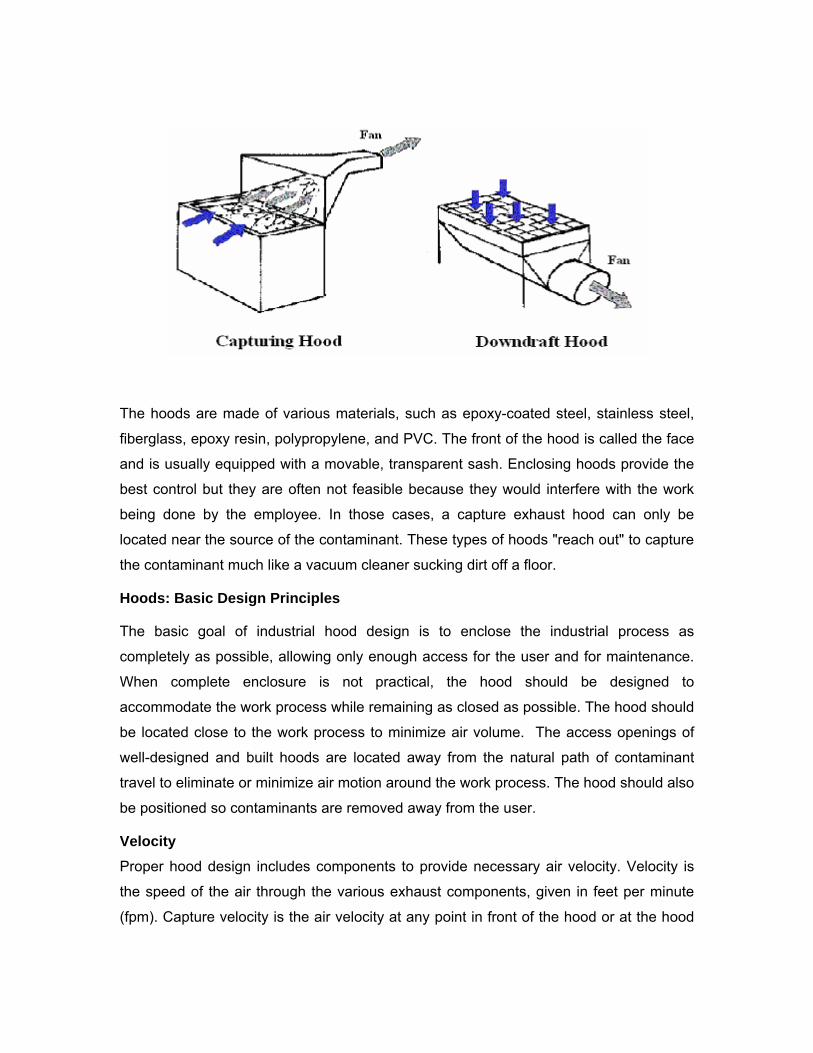
The hoods are made of various materials, such as epoxy-coated steel, stainless steel,
fiberglass, epoxy resin, polypropylene, and PVC. The front of the hood is called the face
and is usually equipped with a movable, transparent sash. Enclosing hoods provide the
best control but they are often not feasible because they would interfere with the work
being done by the employee. In those cases, a capture exhaust hood can only be
located near the source of the contaminant. These types of hoods "reach out" to capture
the contaminant much like a vacuum cleaner sucking dirt off a floor.
Hoods: Basic Design Principles
The basic goal of industrial hood design is to enclose the industrial process as
completely as possible, allowing only enough access for the user and for maintenance.
When complete enclosure is not practical, the hood should be designed to
accommodate the work process while remaining as closed as possible. The hood should
be located close to the work process to minimize air volume. The access openings of
well-designed and built hoods are located away from the natural path of contaminant
travel to eliminate or minimize air motion around the work process. The hood should also
be positioned so contaminants are removed away from the user.
Velocity
Proper hood design includes components to provide necessary air velocity. Velocity is
the speed of the air through the various exhaust components, given in feet per minute
(fpm). Capture velocity is the air velocity at any point in front of the hood or at the hood
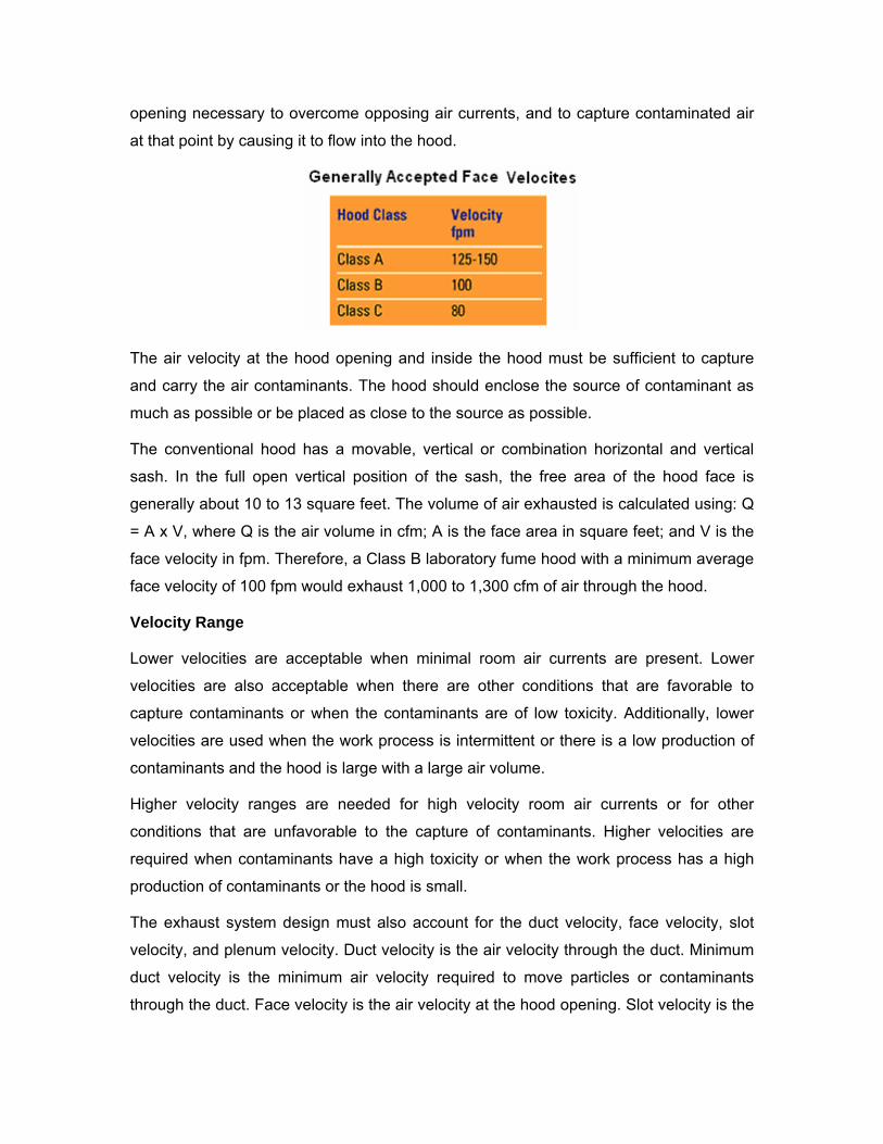
opening necessary to overcome opposing air currents, and to capture contaminated air
at that point by causing it to flow into the hood.
The air velocity at the hood opening and inside the hood must be sufficient to capture
and carry the air contaminants. The hood should enclose the source of contaminant as
much as possible or be placed as close to the source as possible.
The conventional hood has a movable, vertical or combination horizontal and vertical
sash. In the full open vertical position of the sash, the free area of the hood face is
generally about 10 to 13 square feet. The volume of air exhausted is calculated using: Q
= A x V, where Q is the air volume in cfm; A is the face area in square feet; and V is the
face velocity in fpm. Therefore, a Class B laboratory fume hood with a minimum average
face velocity of 100 fpm would exhaust 1,000 to 1,300 cfm of air through the hood.
Velocity Range
Lower velocities are acceptable when minimal room air currents are present. Lower
velocities are also acceptable when there are other conditions that are favorable to
capture contaminants or when the contaminants are of low toxicity. Additionally, lower
velocities are used when the work process is intermittent or there is a low production of
contaminants and the hood is large with a large air volume.
Higher velocity ranges are needed for high velocity room air currents or for other
conditions that are unfavorable to the capture of contaminants. Higher velocities are
required when contaminants have a high toxicity or when the work process has a high
production of contaminants or the hood is small.
The exhaust system design must also account for the duct velocity, face velocity, slot
velocity, and plenum velocity. Duct velocity is the air velocity through the duct. Minimum
duct velocity is the minimum air velocity required to move particles or contaminants
through the duct. Face velocity is the air velocity at the hood opening. Slot velocity is the
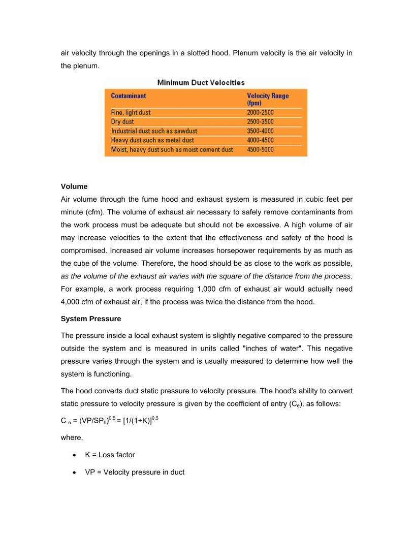
air velocity through the openings in a slotted hood. Plenum velocity is the air velocity in
the plenum.
Volume Air volume through the fume hood and exhaust system is measured in cubic feet per
minute (cfm). The volume of exhaust air necessary to safely remove contaminants from
the work process must be adequate but should not be excessive. A high volume of air
may increase velocities to the extent that the effectiveness and safety of the hood is
compromised. Increased air volume increases horsepower requirements by as much as
the cube of the volume. Therefore, the hood should be as close to the work as possible,
as the volume of the exhaust air varies with the square of the distance from the process.
For example, a work process requiring 1,000 cfm of exhaust air would actually need
4,000 cfm of exhaust air, if the process was twice the distance from the hood.
System Pressure
The pressure inside a local exhaust system is slightly negative compared to the pressure
outside the system and is measured in units called "inches of water". This negative
pressure varies through the system and is usually measured to determine how well the
system is functioning.
The hood converts duct static pressure to velocity pressure. The hood's ability to convert
static pressure to velocity pressure is given by the coefficient of entry (Ce), as follows:
C e = (VP/SPh)0.5 = [1/(1+K)]0.5
where,
• K = Loss factor
• VP = Velocity pressure in duct
• SPh = Absolute static pressure, about 5 duct diameters down the duct from the
hood
Design Points to Note
1. The hood should be designed to achieve good air distribution into the hood
openings so that all the air drawn into the hood helps to control contaminants.
2. High capture velocity with low air volume is desirable. To minimize air-flow
requirements, the operation should be enclosed as much as possible, either with
a ventilated enclosure, side baffles, or curtains. This helps both to contain the
material and to minimize the effect of room air currents.
3. Reducing the amount of contaminants generated or released from the process
reduces ventilation requirements.
4. The purpose of most ventilation systems is to prevent worker inhalation of
contaminants. For this reason, the hood should be located so that contaminants
are not drawn through the worker's breathing zone. This is especially important
where workers lean over an operation, such as an open-surface tank or welding
bench.
5. Hoods must meet the design criteria in the ACGIH Industrial Ventilation Manual
or applicable OSHA standards. Most hood design recommendations account for
cross-drafts that interfere with hood operation. Strong cross-drafts can easily
reduce a hood's effectiveness by 75%. Standard hood designs may not be
adequate to contain highly toxic materials.
Rules of Thumb for Hood Applications
1) Distance between Source and the Hood
The distance between the face of the hood and source must be short to effectively
capture the contaminant. A hood moved from two inches away from a source to four
inches away from a source will require four times the amount of air volume through
the system to provide the same degree of capture. Adding a flange to the edges of
the capturing hood provides more efficient capture of contaminants. Place hood as
close to the source of the contaminant as possible. The required air volume varies
with the square of the distance to the source.
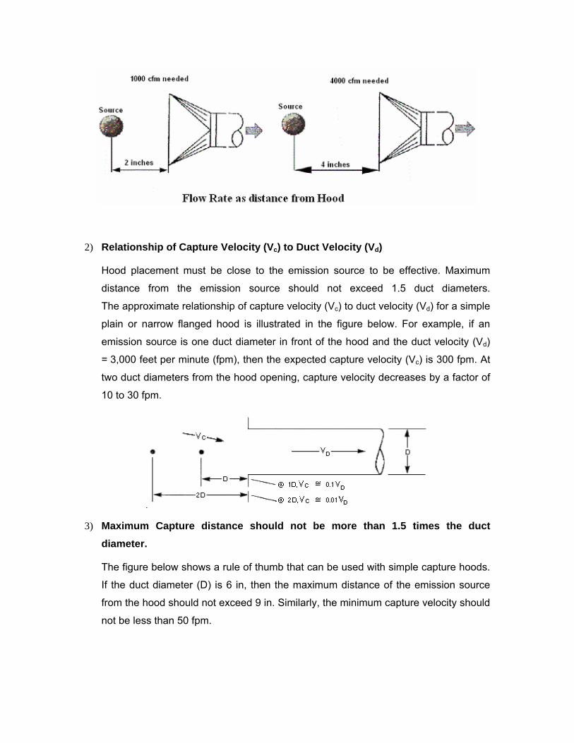
2) Relationship of Capture Velocity (Vc) to Duct Velocity (Vd)
Hood placement must be close to the emission source to be effective. Maximum
distance from the emission source should not exceed 1.5 duct diameters.
The approximate relationship of capture velocity (Vc) to duct velocity (Vd) for a simple
plain or narrow flanged hood is illustrated in the figure below. For example, if an
emission source is one duct diameter in front of the hood and the duct velocity (Vd)
= 3,000 feet per minute (fpm), then the expected capture velocity (Vc) is 300 fpm. At
two duct diameters from the hood opening, capture velocity decreases by a factor of
10 to 30 fpm.
3) Maximum Capture distance should not be more than 1.5 times the duct diameter.
The figure below shows a rule of thumb that can be used with simple capture hoods.
If the duct diameter (D) is 6 in, then the maximum distance of the emission source
from the hood should not exceed 9 in. Similarly, the minimum capture velocity should
not be less than 50 fpm.
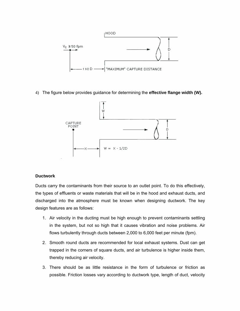
4) The figure below provides guidance for determining the effective flange width (W).
Ductwork
Ducts carry the contaminants from their source to an outlet point. To do this effectively,
the types of effluents or waste materials that will be in the hood and exhaust ducts, and
discharged into the atmosphere must be known when designing ductwork. The key
design features are as follows:
1. Air velocity in the ducting must be high enough to prevent contaminants settling
in the system, but not so high that it causes vibration and noise problems. Air
flows turbulently through ducts between 2,000 to 6,000 feet per minute (fpm).
2. Smooth round ducts are recommended for local exhaust systems. Dust can get
trapped in the corners of square ducts, and air turbulence is higher inside them,
thereby reducing air velocity.
3. There should be as little resistance in the form of turbulence or friction as
possible. Friction losses vary according to ductwork type, length of duct, velocity
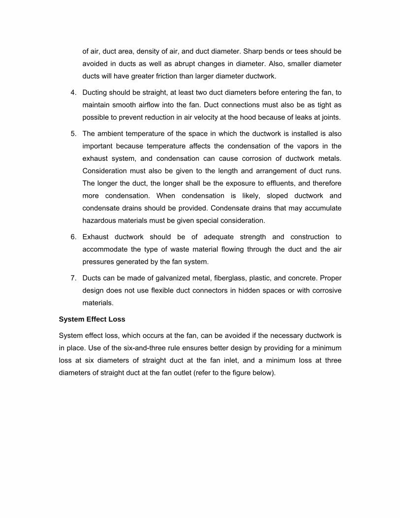
of air, duct area, density of air, and duct diameter. Sharp bends or tees should be
avoided in ducts as well as abrupt changes in diameter. Also, smaller diameter
ducts will have greater friction than larger diameter ductwork.
4. Ducting should be straight, at least two duct diameters before entering the fan, to
maintain smooth airflow into the fan. Duct connections must also be as tight as
possible to prevent reduction in air velocity at the hood because of leaks at joints.
5. The ambient temperature of the space in which the ductwork is installed is also
important because temperature affects the condensation of the vapors in the
exhaust system, and condensation can cause corrosion of ductwork metals.
Consideration must also be given to the length and arrangement of duct runs.
The longer the duct, the longer shall be the exposure to effluents, and therefore
more condensation. When condensation is likely, sloped ductwork and
condensate drains should be provided. Condensate drains that may accumulate
hazardous materials must be given special consideration.
6. Exhaust ductwork should be of adequate strength and construction to
accommodate the type of waste material flowing through the duct and the air
pressures generated by the fan system.
7. Ducts can be made of galvanized metal, fiberglass, plastic, and concrete. Proper
design does not use flexible duct connectors in hidden spaces or with corrosive
materials.
System Effect Loss
System effect loss, which occurs at the fan, can be avoided if the necessary ductwork is
in place. Use of the six-and-three rule ensures better design by providing for a minimum
loss at six diameters of straight duct at the fan inlet, and a minimum loss at three
diameters of straight duct at the fan outlet (refer to the figure below).
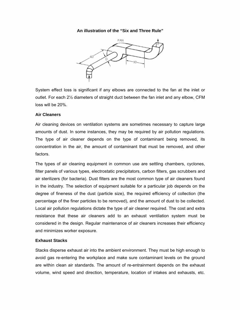
An illustration of the “Six and Three Rule”
System effect loss is significant if any elbows are connected to the fan at the inlet or
outlet. For each 2½ diameters of straight duct between the fan inlet and any elbow, CFM
loss will be 20%.
Air Cleaners
Air cleaning devices on ventilation systems are sometimes necessary to capture large
amounts of dust. In some instances, they may be required by air pollution regulations.
The type of air cleaner depends on the type of contaminant being removed, its
concentration in the air, the amount of contaminant that must be removed, and other
factors.
The types of air cleaning equipment in common use are settling chambers, cyclones,
filter panels of various types, electrostatic precipitators, carbon filters, gas scrubbers and
air sterilizers (for bacteria). Dust filters are the most common type of air cleaners found
in the industry. The selection of equipment suitable for a particular job depends on the
degree of fineness of the dust (particle size), the required efficiency of collection (the
percentage of the finer particles to be removed), and the amount of dust to be collected.
Local air pollution regulations dictate the type of air cleaner required. The cost and extra
resistance that these air cleaners add to an exhaust ventilation system must be
considered in the design. Regular maintenance of air cleaners increases their efficiency
and minimizes worker exposure.
Exhaust Stacks
Stacks disperse exhaust air into the ambient environment. They must be high enough to
avoid gas re-entering the workplace and make sure contaminant levels on the ground
are within clean air standards. The amount of re-entrainment depends on the exhaust
volume, wind speed and direction, temperature, location of intakes and exhausts, etc.
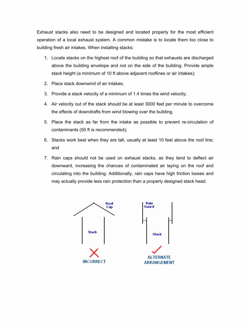
Exhaust stacks also need to be designed and located properly for the most efficient
operation of a local exhaust system. A common mistake is to locate them too close to
building fresh air intakes. When installing stacks:
1. Locate stacks on the highest roof of the building so that exhausts are discharged
above the building envelope and not on the side of the building. Provide ample
stack height (a minimum of 10 ft above adjacent rooflines or air intakes);
2. Place stack downwind of air intakes;
3. Provide a stack velocity of a minimum of 1.4 times the wind velocity;
4. Air velocity out of the stack should be at least 3000 feet per minute to overcome
the effects of downdrafts from wind blowing over the building.
5. Place the stack as far from the intake as possible to prevent re-circulation of
contaminants (50 ft is recommended);
6. Stacks work best when they are tall, usually at least 10 feet above the roof line;
and
7. Rain caps should not be used on exhaust stacks, as they tend to deflect air
downward, increasing the chances of contaminated air laying on the roof and
circulating into the building. Additionally, rain caps have high friction losses and
may actually provide less rain protection than a properly designed stack head.
Type of Local Exhaust System
Local exhaust systems can be classified as: (1) Constant Air Volume, or (2) Variable Air
Volume, based on the method of system operation and control. Each of these
classifications can be further broken down into individual or central systems based on
the arrangement of the major system components, such as fans, plenums, duct mains or
duct branches.
Constant Air Volume Systems
This type of system exhausts a fixed quantity of air from each safety cabinet, fume hood,
or room module. Constant air volume systems will handle the same exhaust air quantity
for any condition. For this reason, the capacities of the exhaust air and supply air
systems will limit the total number of fume hoods and room modules to be installed. This
type of system is flexible with respect to the location of hoods, but may incur high
ownership and operating costs because of the large air volumes handled. These high
costs may impose a limitation on the total number of hoods or modules that can be
installed in the building.
Constant air volume systems are highly stable in operation and simple to balance. In
most installations, there is no need for continuous adjustment of air balance during
normal operation.
Variable Air Volume Systems
Variable air volume systems can shut down inactive fume hoods and room modules.
This capability results in an economic system that reduces the air flow during periods
when some of the hoods and room modules are not in use, and the exhaust air system
is operated at less than full capacity. More freedom in the installation of the hoods and
room modules is possible since the total number of units that may be connected does
not entirely depend on the capacity of the exhaust system.
Variable air volume systems are not as stable in operation as constant air volume
systems are. They are also more difficult to balance and control. Sensitive
instrumentation and controls are required, which result in high initial and maintenance
costs. Reliability in a corrosive atmosphere is highly questionable.
For some applications, the use of balancing dampers in exhaust air ducts is prohibited
by codes. One problem associated with the variable air volume system is the regulation
of the total simultaneous operating usage to match design usage factors. If the collective
area of operating hood openings at any one time exceeds design opening diversity
values, the proper face velocity requirements will not be achieved and personnel could
be endangered. Visual and audible alarms should be equipped on hoods to warn
workers of unsafe air flows.
Individual Exhaust Systems
Individual exhaust air systems use a separate exhaust air fan, exhaust connection, and
discharge duct for each hood or module. They are used in selective applications
requiring special exhaust filtration, special duct or fan construction for corrosive
elements. They are also used to exhaust fumes that have very hazardous elements.
Each fume hood has its own exhaust connection, duct and fan, which does not directly
affect the operation of any other area of the building; thereby permitting selective
operation of individual hoods and modules by starting or stopping the fan motor.
Normally, the exhaust fan is always on and is interlocked electrically with the supply fan,
so that when the exhaust goes off the supply fan does too.
Although more fans are used than for central systems, the overall space requirements
are usually less for individual systems because of the small, direct duct connection.
Individual fume hood exhaust systems are inexpensive for small systems having only a
few fans. However, if the system is large, the initial investment and the operating costs
are high because of the greater number of fans, roof penetrations, and controls, as well
as the more extensive ductwork and wiring that must be installed and maintained. The
maintenance costs are also high, but since each hood has its own ductwork, exhausted
air from fume hoods does not mix and shutdowns for repairs or maintenance are
localized.
The shutdown of individual exhaust air systems will upset the proper directional air flow
and may cause potentially hazardous contaminants and odors to flow into the corridor
and adjacent rooms. If this type of system is used, precautions to reverse air flow (such
as air locks) should be provided.
Central Exhaust Systems
Facilities that use many fume hoods usually have a central exhaust system. Central
exhaust air systems consist of a common suction plenum, a primary fan, a standby fan
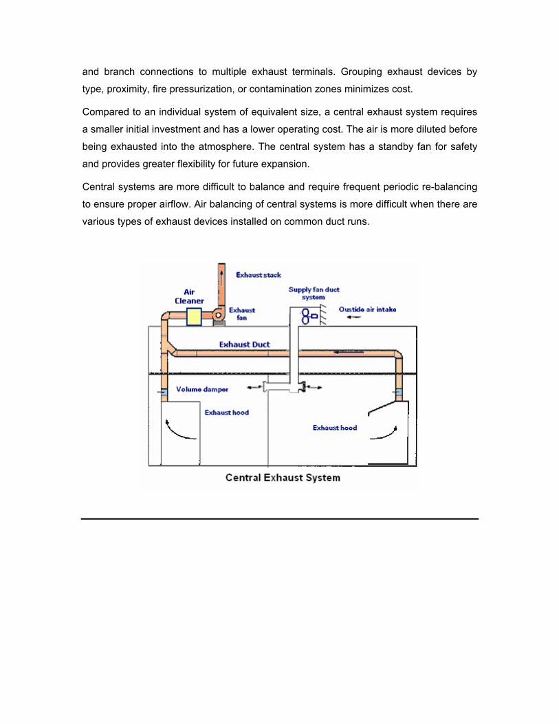
and branch connections to multiple exhaust terminals. Grouping exhaust devices by
type, proximity, fire pressurization, or contamination zones minimizes cost.
Compared to an individual system of equivalent size, a central exhaust system requires
a smaller initial investment and has a lower operating cost. The air is more diluted before
being exhausted into the atmosphere. The central system has a standby fan for safety
and provides greater flexibility for future expansion.
Central systems are more difficult to balance and require frequent periodic re-balancing
to ensure proper airflow. Air balancing of central systems is more difficult when there are
various types of exhaust devices installed on common duct runs.
SECTION -6: GENERAL SYSTEM DESIGN CONSIDERATIONS
1. Aim for full cross-ventilation of the space. The cross-ventilation is based on the
natural tendency of the air to move from high to low pressures. The warm air
moves naturally, producing air displacement through the building (natural
ventilation).
2. Air replacement should be provided at the minimum rate of 1 sq-ft of free area
per 600 CFM of air moved. Air replacement grilles usually have a free area of
approximately 60%. For example, a 12” square grille will have a face area of 12”
x 12” = 1 sq-ft; therefore, 60% of 1 sq-ft = 0.6 sq-ft free area. This means that this
grille will provide air replacement for the rate of 0.6 x 600 = 360 CFM. Use
sufficient and correctly sized grilles to keep supply and extract air velocities
between 300 feet per minute and 600 feet per minute, if possible.
3. Locate units at high level, and inlet grilles just above head level to avoid
uncomfortable draughts to the occupants. The natural upward convection
currents and the secondary entrained air movements from the inlet grilles
(caused more or less by the horizontal “jet” of air) will give sufficient gentle air
turbulence around the breathing level to maintain a feeling of freshness.
4. Locate intake and exhaust fans to make use of prevailing winds. Locate fans and
intake ventilators for maximum sweeping effect over the working area. If filters
are used on gravity intakes, size intake ventilators to keep intake losses below
1/8 in-wg.
5. In larger industrial buildings, temperature differences encourage the upward flow
of air. If the building contains the hot processes, dusts and fumes are carried
rapidly up to be discharged through roof ventilators or fans. Always extract from
as high as possible to prevent the collection of heated air under the roof or ceiling
from extending downwards near breathing level. In such cases, fans at or near
the ridge are ideal with air replacement from side windows above the head level.
This method assists the natural tendency for warmer air to rise, and the quicker
this ‘fug’ is removed from high levels, the better will be the conditions at breathing
levels.
6. When considering air replacement, the location of suitable air intake points is as
important as the location of the extract units. Note that with ventilation alone, the
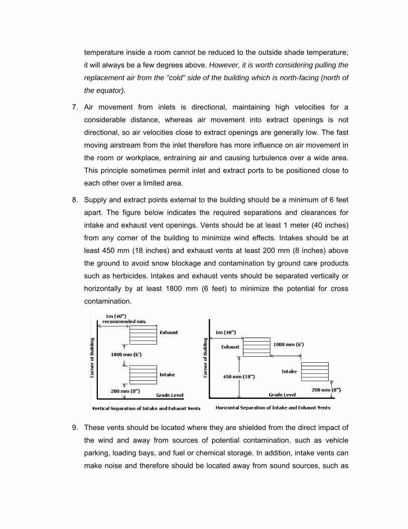
temperature inside a room cannot be reduced to the outside shade temperature;
it will always be a few degrees above. However, it is worth considering pulling the
replacement air from the "cold" side of the building which is north-facing (north of
the equator).
7. Air movement from inlets is directional, maintaining high velocities for a
considerable distance, whereas air movement into extract openings is not
directional, so air velocities close to extract openings are generally low. The fast
moving airstream from the inlet therefore has more influence on air movement in
the room or workplace, entraining air and causing turbulence over a wide area.
This principle sometimes permit inlet and extract ports to be positioned close to
each other over a limited area.
8. Supply and extract points external to the building should be a minimum of 6 feet
apart. The figure below indicates the required separations and clearances for
intake and exhaust vent openings. Vents should be at least 1 meter (40 inches)
from any corner of the building to minimize wind effects. Intakes should be at
least 450 mm (18 inches) and exhaust vents at least 200 mm (8 inches) above
the ground to avoid snow blockage and contamination by ground care products
such as herbicides. Intakes and exhaust vents should be separated vertically or
horizontally by at least 1800 mm (6 feet) to minimize the potential for cross
contamination.
9. These vents should be located where they are shielded from the direct impact of
the wind and away from sources of potential contamination, such as vehicle
parking, loading bays, and fuel or chemical storage. In addition, intake vents can
make noise and therefore should be located away from sound sources, such as
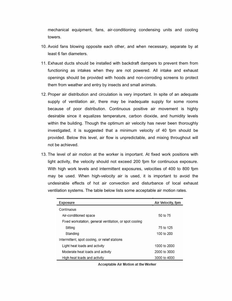
mechanical equipment, fans, air-conditioning condensing units and cooling
towers.
10. Avoid fans blowing opposite each other, and when necessary, separate by at
least 6 fan diameters.
11. Exhaust ducts should be installed with backdraft dampers to prevent them from
functioning as intakes when they are not powered. All intake and exhaust
openings should be provided with hoods and non-corroding screens to protect
them from weather and entry by insects and small animals.
12. Proper air distribution and circulation is very important. In spite of an adequate
supply of ventilation air, there may be inadequate supply for some rooms
because of poor distribution. Continuous positive air movement is highly
desirable since it equalizes temperature, carbon dioxide, and humidity levels
within the building. Though the optimum air velocity has never been thoroughly
investigated, it is suggested that a minimum velocity of 40 fpm should be
provided. Below this level, air flow is unpredictable, and mixing throughout will
not be achieved.
13. The level of air motion at the worker is important. At fixed work positions with
light activity, the velocity should not exceed 200 fpm for continuous exposure.
With high work levels and intermittent exposures, velocities of 400 to 800 fpm
may be used. When high-velocity air is used, it is important to avoid the
undesirable effects of hot air convection and disturbance of local exhaust
ventilation systems. The table below lists some acceptable air motion rates.
14. Use Class B insulated motors where ambient temperatures are expected to be
high for air-over motor conditions.
15. If air moving over motors contains hazardous chemicals or particles, use
explosion-proof motors mounted in or out of the airstream, depending on job
requirements. For hazardous atmosphere applications use fans of non-sparking
construction.
16. If the room is very wide, say over 80 ft, it may be necessary to extract centrally
and bring in replacement air along each side.
17. Design the system for Zero Temperature Stratification - Temperature
stratification in simple word means the vertical temperature difference between
feet and head. It is a common problem caused by convection; the tendency of
light-warm air to rise and heavier-cooler air to sink. If air is not properly mixed by
the ventilation system, the temperature near the ceiling can be several degrees
warmer than that at the floor level.
18. Absence of Drafts: Large vertical surfaces can also produce a significant flow of
naturally-convecting air, producing complaints of draftiness. As a rule of thumb,
horizontal temperature differences should not exceed 10°C and vertical
temperature differences should not exceed 5°C. To avoid draft, ASHRAE
suggests that air speeds should be below 40 fpm with ventilation systems that
create 30-60% turbulence intensity. Use ceiling diffusers with 45° or 90° angles
over 10° angles because 10° angles can cause draught at the head. Circulated
air should be no more than 2°F different from the ambient space temperature.
19. To provide effective general ventilation for heat relief by either natural or
mechanical supply, the air must be delivered in the work zones (no more than 10
ft above the floor) with an appreciable air velocity. A sufficient exhaust volume is
necessary to remove the heat liberated in the space. Local relief systems may
require supplementary supply air for heat removal.
20. Modifications to a room or workplace, particularly the installation of internal
partitions, may affect the circulation of air and reduce the effectiveness of
ventilation. Where part of a workplace is blocked or partitioned off, for example,
to create internal offices, it is important to ensure that the ventilation system
extends to all areas and that suitably sized air grilles are incorporated in the
partition walls or doors if necessary. In some cases, supplementary fans may be
required to promote air movement and prevent localized stagnation.
Fire and Safety Considerations
The installation of a mechanical system may affect the fire risk within the building; both
with regards to structural protection and means of escape in case of fire. Also, it may
influence any necessary fire venting or fight fighting considerations.
The extent and detail of statutory control and other special interests may vary
considerably according to the design, use, occupation and location of the building, and
the type of system of mechanical ventilation proposed. It is particularly important that the
appropriate authority be fully consulted at an early stage.
The degree of control and the requirements imposed vary according to the
circumstances of the case; depending on whether the control is related to the means of
escape (e.g. clearance for smoke in the event of fire), structural fire precautions (e.g.
maintenance of structural fire separations), health of occupants, conservation of energy
or any combination of these. Full details may have to be approved by the local authority
in such cases as:
1. Buildings controlled from the point of view of the means of escape where
recirculation of air is involved, and/or where pressurized staircases are
contemplated as part of the smoke control arrangements;
2. Places of public gathering/entertainment;
3. Flats and apartments where mechanical ventilation is necessary to lobby and
corridors as part of the smoke control arrangements;
4. Large garages and car parks, hotels, parts of buildings used for trades or
processes involving a special risk, departmental stores and similar shop risks in
large buildings; and
5. Certain areas of the building where separate and independent mechanical
ventilation systems are required. These include: lavatories, toilets, garages,
kitchens and car parks; staircases for control of smoke; boiler chambers; and
areas containing oil immersed electric plants or hazardous materials.
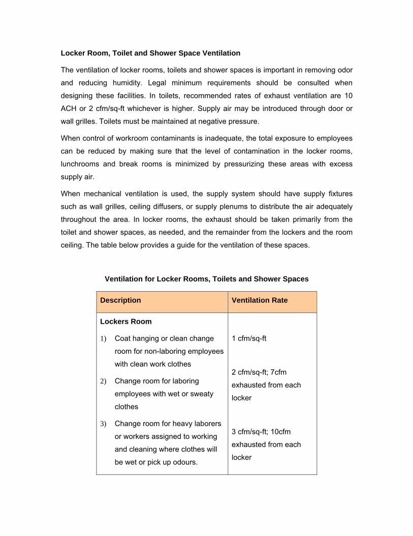
Locker Room, Toilet and Shower Space Ventilation
The ventilation of locker rooms, toilets and shower spaces is important in removing odor
and reducing humidity. Legal minimum requirements should be consulted when
designing these facilities. In toilets, recommended rates of exhaust ventilation are 10
ACH or 2 cfm/sq-ft whichever is higher. Supply air may be introduced through door or
wall grilles. Toilets must be maintained at negative pressure.
When control of workroom contaminants is inadequate, the total exposure to employees
can be reduced by making sure that the level of contamination in the locker rooms,
lunchrooms and break rooms is minimized by pressurizing these areas with excess
supply air.
When mechanical ventilation is used, the supply system should have supply fixtures
such as wall grilles, ceiling diffusers, or supply plenums to distribute the air adequately
throughout the area. In locker rooms, the exhaust should be taken primarily from the
toilet and shower spaces, as needed, and the remainder from the lockers and the room
ceiling. The table below provides a guide for the ventilation of these spaces.
Ventilation for Locker Rooms, Toilets and Shower Spaces
Description Ventilation Rate
Lockers Room
1) Coat hanging or clean change
room for non-laboring employees
with clean work clothes
2) Change room for laboring
employees with wet or sweaty
clothes
3) Change room for heavy laborers
or workers assigned to working
and cleaning where clothes will
be wet or pick up odours.
1 cfm/sq-ft
2 cfm/sq-ft; 7cfm
exhausted from each
locker
3 cfm/sq-ft; 10cfm
exhausted from each
locker
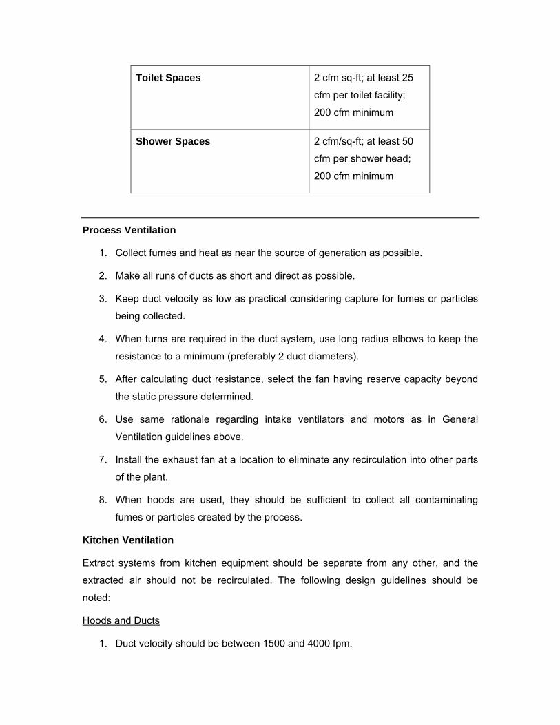
Toilet Spaces 2 cfm sq-ft; at least 25
cfm per toilet facility;
200 cfm minimum
Shower Spaces 2 cfm/sq-ft; at least 50
cfm per shower head;
200 cfm minimum
Process Ventilation
1. Collect fumes and heat as near the source of generation as possible.
2. Make all runs of ducts as short and direct as possible.
3. Keep duct velocity as low as practical considering capture for fumes or particles
being collected.
4. When turns are required in the duct system, use long radius elbows to keep the
resistance to a minimum (preferably 2 duct diameters).
5. After calculating duct resistance, select the fan having reserve capacity beyond
the static pressure determined.
6. Use same rationale regarding intake ventilators and motors as in General
Ventilation guidelines above.
7. Install the exhaust fan at a location to eliminate any recirculation into other parts
of the plant.
8. When hoods are used, they should be sufficient to collect all contaminating
fumes or particles created by the process.
Kitchen Ventilation
Extract systems from kitchen equipment should be separate from any other, and the
extracted air should not be recirculated. The following design guidelines should be
noted:
Hoods and Ducts
1. Duct velocity should be between 1500 and 4000 fpm.
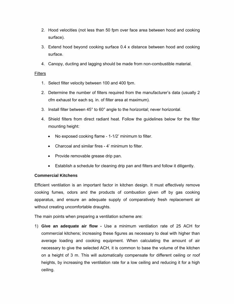
2. Hood velocities (not less than 50 fpm over face area between hood and cooking
surface).
3. Extend hood beyond cooking surface 0.4 x distance between hood and cooking
surface.
4. Canopy, ducting and lagging should be made from non-combustible material.
Filters
1. Select filter velocity between 100 and 400 fpm.
2. Determine the number of filters required from the manufacturer’s data (usually 2
cfm exhaust for each sq. in. of filter area at maximum).
3. Install filter between 45° to 60° angle to the horizontal; never horizontal.
4. Shield filters from direct radiant heat. Follow the guidelines below for the filter
mounting height:
• No exposed cooking flame - 1-1/2’ minimum to filter.
• Charcoal and similar fires - 4’ minimum to filter.
• Provide removable grease drip pan.
• Establish a schedule for cleaning drip pan and filters and follow it diligently.
Commercial Kitchens
Efficient ventilation is an important factor in kitchen design. It must effectively remove
cooking fumes, odors and the products of combustion given off by gas cooking
apparatus, and ensure an adequate supply of comparatively fresh replacement air
without creating uncomfortable draughts.
The main points when preparing a ventilation scheme are:
1) Give an adequate air flow - Use a minimum ventilation rate of 25 ACH for
commercial kitchens; increasing these figures as necessary to deal with higher than
average loading and cooking equipment. When calculating the amount of air
necessary to give the selected ACH, it is common to base the volume of the kitchen
on a height of 3 m. This will automatically compensate for different ceiling or roof
heights, by increasing the ventilation rate for a low ceiling and reducing it for a high
ceiling.
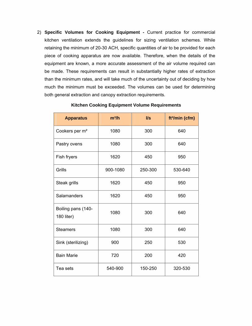
2) Specific Volumes for Cooking Equipment - Current practice for commercial
kitchen ventilation extends the guidelines for sizing ventilation schemes. While
retaining the minimum of 20-30 ACH, specific quantities of air to be provided for each
piece of cooking apparatus are now available. Therefore, when the details of the
equipment are known, a more accurate assessment of the air volume required can
be made. These requirements can result in substantially higher rates of extraction
than the minimum rates, and will take much of the uncertainty out of deciding by how
much the minimum must be exceeded. The volumes can be used for determining
both general extraction and canopy extraction requirements.
Kitchen Cooking Equipment Volume Requirements
Apparatus m³/h l/s ft³/min (cfm)
Cookers per m² 1080 300 640
Pastry ovens 1080 300 640
Fish fryers 1620 450 950
Grills 900-1080 250-300 530-640
Steak grills 1620 450 950
Salamanders 1620 450 950
Boiling pans (140-
180 liter) 1080 300 640
Steamers 1080 300 640
Sink (sterilizing) 900 250 530
Bain Marie 720 200 420
Tea sets 540-900 150-250 320-530
Alternatively, calculations can be based on the number of meals prepared per hour,
multiplied by 10 to 15, to give an extract volume in liters per second.
Locate extract units as high as possible and as near the source of the fumes as
convenient. Hot moist fumes from cooking operations rise fast to ceiling level, and
unless they are removed quickly from that level, they will spread over ceiling, walls and
windows depositing the moisture content and grease as they condense on the cooler
surfaces. Roof lights and lantern lights are sometimes an ideal location for extract units
in a commercial kitchen, as they are usually over some cooking equipment at or near the
center of the kitchen, and it is a simple matter to fit roof fans in the glazing. If due to
some obstruction, it is not possible to site the unit at a high level directly above the
cooker, then keep it at a high level and move it a foot or two to one side. This is better
than putting the unit immediately above the cooker but only half way up the wall, as the
velocity of the steam and fumes would carry them past the unit to ceiling level where
they would spread horizontally and hang about for some time before cooling sufficiently
to drop to the level of the extract point. Low siting of the unit is a common fault in
domestic kitchens, as this allows cooking fumes to float through the top of a doorway
before they can sink low enough to be extracted by the fan.
3) Use canopies over 'heavy' cooking equipment, particularly in commercial kitchens,
to collect and 'hold' the fumes at the source. The removal of fumes and steam from
cooking and industrial processes should be done as near to the source as possible.
Warm fumes and steam rise quickly and spread over a comparatively large area of
the kitchen and must be 'picked up' and removed quickly. To deal with this sort of
local problem by increasing the general ventilation rate of the room is not always
economical or convenient due to the large volume of air extraction necessary to
reduce the spread of the fumes. In such cases, a canopy or hood would be fitted
directly above the equipment and overlapped by up to 300 mm all around to collect
the fumes. The canopies and fans should be of sufficient large capacity to 'hold' and
carry away the fumes without undue spillage from the mouth of the canopy. To
achieve this, the velocity of the air through the open area between the canopy and
the equipment must be sufficiently high to draw in fumes near the edge of the
equipment against the eddying effects of local draughts which could be caused by
the movement of people around the equipment.
Estimating Air Volume
Where the items of cooking equipment to be placed under a canopy are known, the
total of the volumes of air required for each piece of equipment will constitute the
extract volume to be provided by the canopy extract fans. Where the equipment is
not known, the formula shown below can be used. This formula uses the base area
of the canopy, rather than the open perimeter area used in earlier formulae, and
more closely matches the volume of hot air rising from the cooking equipment. The
volumes obtained by this formula should be regarded as minimums and no harm will
result if they are increased by 50%.
Vol. m³/s = L (m) × W (m) × K,
where,
K =
• 0.25 for Domestic
• 0.30 for Light Commercial
• 0.40 for Commercial and Light Industrial
• 0.50 for Heavy Commercial and Industrial
The factor K represents the face velocity (m/s) of the airflow at the canopy.
Example
A canteen kitchen (equivalent to a light commercial kitchen having face velocity of 0.3
m/s) is to have a canopy 3 m x 1.25 m and covering cooking equipment not yet
specified. Find the air volume required.
Solution
Air req. m³/s = 3 × 1.25 × 0.3 = 1.125 m³/s (4050 m³/h)
Other points to consider:
1) Minimum height from floor to underside of canopy should be 2 m;
2) Air replacement should be based on 75-85% of extracted air;
3) Temperature of replacement air must not be below 10°C when coming into contact
with cooked food;
4) Maximum duct velocity should be 1200 feet per minute;
5) Plastic flexible ducting should not be used to extract from kitchen canopies, as it is
very difficult to clear and would constitute a fire hazard. Steel ductwork should be
used, with adequate access panels for cleaning. In special cases, flexible metal
ducting could be used, but only where it is short enough to be easily dismantled for
cleaning or replacement. Canopy grease filters are necessary to remove the bulk of
the oil and fat droplets from the air before it passes along ducting and through extract
fans;
6) Ensure ample air replacement openings are well distributed to eliminate local
draughts and to spread the supply of fresh air. Some air replacement from adjoining
rooms is not a disadvantage, as the flow of air through the doorways will reduce the
possibility of fumes from the kitchen passing through to these adjoining rooms.
Extract units should be switched on as soon as any cooking apparatus is in use to
prevent a build-up of hot fumes, and should be left running for 20 to 30 minutes after
cooking is finished to clear away any residual fumes and hot air convected from the
cooker surfaces;
7) Where a fish fryer is used, no fire dampers should be fitted in the ventilation extract
duct unless any statutory requirement exists otherwise, but adequate cleaning
facilities should be provided; and
8) Canopy, ducting and lagging should be made from non-combustible material. Where
ducting passes through other floors between the kitchen and the external weathering
cowl, it should be enclosed in fire-resisting construction at least equal to the standard
of fire resistance required for the floor.
Laboratory Ventilation and Chemical Storage Areas
1. Provide a minimum of ten air exchanges per hour;
2. The ventilation system should shut down when the fire alarm is activated and be
capable of manual restarting;
3. Pressure differences should be maintained such that air flows from low to high
hazard spaces;
4. Dilution ventilation systems should have the capacity to increase air flow under
emergency conditions such as a spill; and
5. All chemicals should be maintained in a properly designed chemical storage
area. This includes cabinets for flammables, poisons and corrosives. The venting
of flammables cabinets is not recommended, unless local codes require it. The
National Fire Protection Association standards do not require venting but if the
cabinet is vented, it must not compromise the integrity of the cabinet. If you vent
the cabinet, be sure you consult with an engineer or industrial hygienist to avoid
compromising the cabinet or violating the code.
Local Exhaust Ventilation for Fume hoods:
1. The chemical fume hood is the primary engineering control for limiting exposure
in laboratories and often serves as the OSHA designated area.
2. Locate the fume hood to avoid doorways, high traffic areas, windows or any other
structure which might create disruptions in air flow. Note: A hood having a face
velocity of 100 fpm is equivalent to an air flow rate of 1 mile per hour. Opening or
closing a door can create a 5 mph air flow and compromise the fume hood.
3. The hood should have a face velocity of 60-100 fpm of non turbulent air.
4. The hood should be equipped with an airfoil to reduce turbulence at the hood
opening.
5. The top slot of the hood should be fixed at 0.5 to 0.75 inch opening and the
bottom slot should be fully open. Note: Consult the manufacturer’s
recommendations to achieve maximum efficiency.
6. The fan should be located outside the building.
7. Exhausts should be located away from air intakes and should project above the
roofline. NFPA Standards require a minimum of 7 feet.
8. Fume hoods should be equipped with a velocity indicator. Ideally the hood should
be equipped with a velocity alarm.
9. Fume hoods should not be used to store chemicals or equipment.
10. The minimum amount of equipment and/or chemicals for the specific procedure
should be in the fume hood.
11. Locate equipment at least 6 inches behind the sash opening.
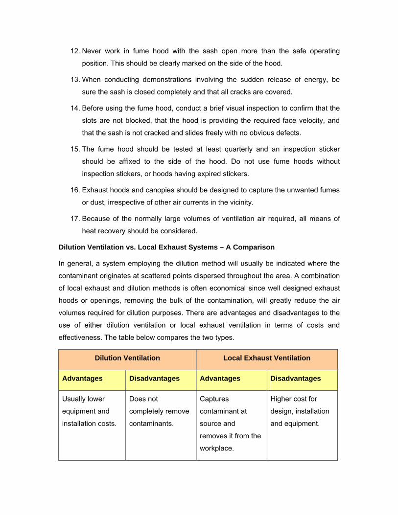
12. Never work in fume hood with the sash open more than the safe operating
position. This should be clearly marked on the side of the hood.
13. When conducting demonstrations involving the sudden release of energy, be
sure the sash is closed completely and that all cracks are covered.
14. Before using the fume hood, conduct a brief visual inspection to confirm that the
slots are not blocked, that the hood is providing the required face velocity, and
that the sash is not cracked and slides freely with no obvious defects.
15. The fume hood should be tested at least quarterly and an inspection sticker
should be affixed to the side of the hood. Do not use fume hoods without
inspection stickers, or hoods having expired stickers.
16. Exhaust hoods and canopies should be designed to capture the unwanted fumes
or dust, irrespective of other air currents in the vicinity.
17. Because of the normally large volumes of ventilation air required, all means of
heat recovery should be considered.
Dilution Ventilation vs. Local Exhaust Systems – A Comparison
In general, a system employing the dilution method will usually be indicated where the
contaminant originates at scattered points dispersed throughout the area. A combination
of local exhaust and dilution methods is often economical since well designed exhaust
hoods or openings, removing the bulk of the contamination, will greatly reduce the air
volumes required for dilution purposes. There are advantages and disadvantages to the
use of either dilution ventilation or local exhaust ventilation in terms of costs and
effectiveness. The table below compares the two types.
Dilution Ventilation Local Exhaust Ventilation
Advantages Disadvantages Advantages Disadvantages
Usually lower
equipment and
installation costs.
Does not
completely remove
contaminants.
Captures
contaminant at
source and
removes it from the
workplace.
Higher cost for
design, installation
and equipment.
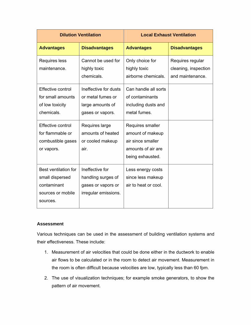
Dilution Ventilation Local Exhaust Ventilation
Advantages Disadvantages Advantages Disadvantages
Requires less
maintenance.
Cannot be used for
highly toxic
chemicals.
Only choice for
highly toxic
airborne chemicals.
Requires regular
cleaning, inspection
and maintenance.
Effective control
for small amounts
of low toxicity
chemicals.
Ineffective for dusts
or metal fumes or
large amounts of
gases or vapors.
Can handle all sorts
of contaminants
including dusts and
metal fumes.
Effective control
for flammable or
combustible gases
or vapors.
Requires large
amounts of heated
or cooled makeup
air.
Requires smaller
amount of makeup
air since smaller
amounts of air are
being exhausted.
Best ventilation for
small dispersed
contaminant
sources or mobile
sources.
Ineffective for
handling surges of
gases or vapors or
irregular emissions.
Less energy costs
since less makeup
air to heat or cool.
Assessment
Various techniques can be used in the assessment of building ventilation systems and
their effectiveness. These include:
1. Measurement of air velocities that could be done either in the ductwork to enable
air flows to be calculated or in the room to detect air movement. Measurement in
the room is often difficult because velocities are low, typically less than 60 fpm.
2. The use of visualization techniques; for example smoke generators, to show the
pattern of air movement.
3. The use of tracer gases such as sulphur hexafluoride, or particles such as
potassium iodide, to detect and trace air movement through a building. Tracer
gases can also be used to measure actual ventilation air change rates in the
building. This is done by releasing the tracer once and then measuring the rate of
decay (i.e. fall in concentration), or by continuously releasing tracer gases at a
known rate and measuring the equilibrium concentration.
4. Monitoring for airborne contaminants from a process or combustion equipment,
and monitoring for carbon dioxide from building occupants.
Note that for tracers or for airborne contaminants, there is a specialized technique that
should be carried out by competent professionals with suitable equipment.
____________________________________________________________________