Embed Size (px)
Citation preview
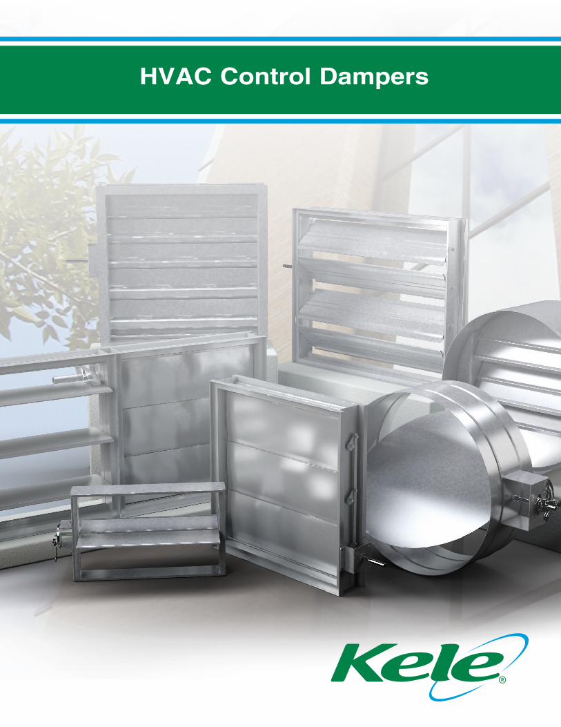
HVAC Control Dampers
2
HVAC Control Dampers
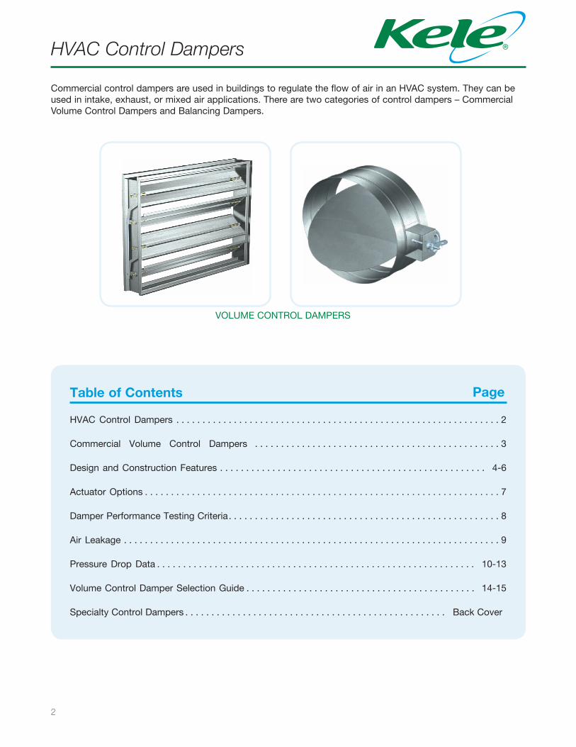
Commercial control dampers are used in buildings to regulate the flow of air in an HVAC system. They can be used in intake, exhaust, or mixed air applications. There are two categories of control dampers – Commercial Volume Control Dampers and Balancing Dampers.
VOLUME CONTROL DAMPERS
Table of Contents
HVAC Control Dampers . . . . . . . . . . . . . . . . . . . . . . . . . . . . . . . . . . . . . . . . . . . . . . . . . . . . . . . . . . . . . . 2
Commercial Volume Control Dampers . . . . . . . . . . . . . . . . . . . . . . . . . . . . . . . . . . . . . . . . . . . . . . . 3
Design and Construction Features . . . . . . . . . . . . . . . . . . . . . . . . . . . . . . . . . . . . . . . . . . . . . . . . . . . 4-6
Actuator Options . . . . . . . . . . . . . . . . . . . . . . . . . . . . . . . . . . . . . . . . . . . . . . . . . . . . . . . . . . . . . . . . . . . . 7
Damper Performance Testing Criteria . . . . . . . . . . . . . . . . . . . . . . . . . . . . . . . . . . . . . . . . . . . . . . . . . . . . 8
Air Leakage . . . . . . . . . . . . . . . . . . . . . . . . . . . . . . . . . . . . . . . . . . . . . . . . . . . . . . . . . . . . . . . . . . . . . . . . 9
Pressure Drop Data . . . . . . . . . . . . . . . . . . . . . . . . . . . . . . . . . . . . . . . . . . . . . . . . . . . . . . . . . . . . . 10-13
Volume Control Damper Selection Guide . . . . . . . . . . . . . . . . . . . . . . . . . . . . . . . . . . . . . . . . . . . . 14-15
Specialty Control Dampers . . . . . . . . . . . . . . . . . . . . . . . . . . . . . . . . . . . . . . . . . . . . . . . . . . Back Cover
Page
3
Commercial Volume Control Dampers
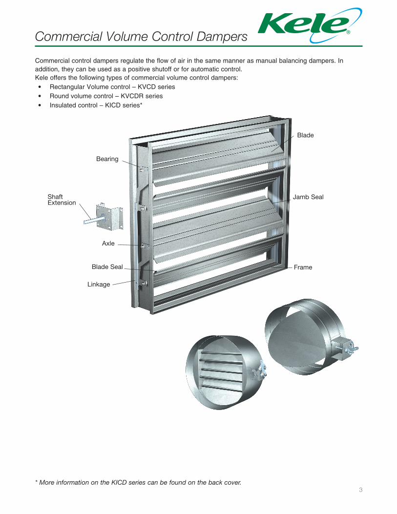
Axle
Bearing
Blade
Frame
Linkage
Jamb Seal
Blade Seal
ShaftExtension
Commercial control dampers regulate the flow of air in the same manner as manual balancing dampers. In addition, they can be used as a positive shutoff or for automatic control.Kele offers the following types of commercial volume control dampers:• Rectangular Volume control – KVCD series• Round volume control – KVCDR series• Insulated control – KICD series*
* More information on the KICD series can be found on the back cover.
4
Design and Construction Features
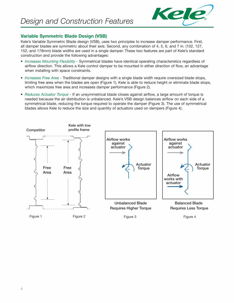
Variable Symmetric Blade Design (VSB)Kele’s Variable Symmetric Blade design (VSB), uses two principles to increase damper performance. First, all damper blades are symmetric about their axis. Second, any combination of 4, 5, 6, and 7 in. (102, 127, 152, and 178mm) blade widths are used in a single damper. These two features are part of Kele’s standard construction and provide the following advantages:
• Increases Mounting Flexibility - Symmetrical blades have identical operating characteristics regardless ofairflow direction. This allows a Kele control damper to be mounted in either direction of flow, an advantagewhen installing with space constraints.
• Increases Free Area - Traditional damper designs with a single blade width require oversized blade stops,limiting free area when the blades are open (Figure 1). Kele is able to reduce height or eliminate blade stops,which maximizes free area and increases damper performance (Figure 2).
• Reduces Actuator Torque - If an unsymmetrical blade closes against airflow, a large amount of torque isneeded because the air distribution is unbalanced. Kele’s VSB design balances airflow on each side of asymmetrical blade, reducing the torque required to operate the damper (Figure 3). The use of symmetricalblades allows Kele to reduce the size and quantity of actuators used on dampers (Figure 4).
ActuatorTorque
ActuatorTorque
Airflow worksagainstactuator
Airflow worksagainstactuator
Airflowworks with
actuator
Unbalanced BladeRequires Higher Torque
Balanced Blade Requires Less Torque
Free AreaMaximum Reduced
Greenheckwith VSB with 6 in. blades
with 7 in. blades
unbalancedblade
FreeArea
FreeArea
CompetitorKele with low profile frame
Figure 1 Figure 2 Figure 4Figure 3
5
Design and Construction Features
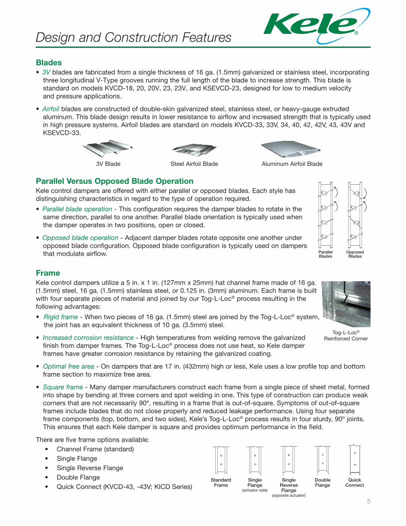
Blades• 3V blades are fabricated from a single thickness of 16 ga. (1.5mm) galvanized or stainless steel, incorporating
three longitudinal V-Type grooves running the full length of the blade to increase strength. This blade is standard on models KVCD-18, 20, 20V, 23, 23V, and KSEVCD-23, designed for low to medium velocity and pressure applications.
• Airfoil blades are constructed of double-skin galvanized steel, stainless steel, or heavy-gauge extrudedaluminum. This blade design results in lower resistance to airflow and increased strength that is typically usedin high pressure systems. Airfoil blades are standard on models KVCD-33, 33V, 34, 40, 42, 42V, 43, 43V andKSEVCD-33.
ParallelBlades
OpposedBlades
3V Blade Steel Airfoil Blade Aluminum Airfoil Blade
FrameKele control dampers utilize a 5 in. x 1 in. (127mm x 25mm) hat channel frame made of 16 ga. (1.5mm) steel, 16 ga. (1.5mm) stainless steel, or 0.125 in. (3mm) aluminum. Each frame is built with four separate pieces of material and joined by our Tog-L-Loc® process resulting in the following advantages:
• Rigid frame - When two pieces of 16 ga. (1.5mm) steel are joined by the Tog-L-Loc® system,the joint has an equivalent thickness of 10 ga. (3.5mm) steel.
• Increased corrosion resistance - High temperatures from welding remove the galvanizedfinish from damper frames. The Tog-L-Loc® process does not use heat, so Kele damperframes have greater corrosion resistance by retaining the galvanized coating.
• Optimal free area - On dampers that are 17 in. (432mm) high or less, Kele uses a low profile top and bottomframe section to maximize free area.
• Square frame - Many damper manufacturers construct each frame from a single piece of sheet metal, formedinto shape by bending at three corners and spot welding in one. This type of construction can produce weakcorners that are not necessarily 90º, resulting in a frame that is out-of-square. Symptoms of out-of-squareframes include blades that do not close properly and reduced leakage performance. Using four separateframe components (top, bottom, and two sides), Kele’s Tog-L-Loc® process results in four sturdy, 90º joints.This ensures that each Kele damper is square and provides optimum performance in the field.
There are five frame options available:• Channel Frame (standard)• Single Flange• Single Reverse Flange• Double Flange• Quick Connect (KVCD-43, -43V; KICD Series)
StandardFrame
DoubleFlange
SingleFlange
SingleReverse Flange(actuator
side) (oppositeactuator)
QuickConnect
StandardFrame
DoubleFlange
QuickConnect
SingleFlange
(actuator side)
SingleReverseFlange
(opposite actuator)
Tog-L-Loc®
Reinforced Corner
Parallel Versus Opposed Blade OperationKele control dampers are offered with either parallel or opposed blades. Each style has distinguishing characteristics in regard to the type of operation required.
• Parallel blade operation - This configuration requires the damper blades to rotate in thesame direction, parallel to one another. Parallel blade orientation is typically used whenthe damper operates in two positions, open or closed.
• Opposed blade operation - Adjacent damper blades rotate opposite one another underopposed blade configuration. Opposed blade configuration is typically used on dampersthat modulate airflow.
6
Design and Construction Features
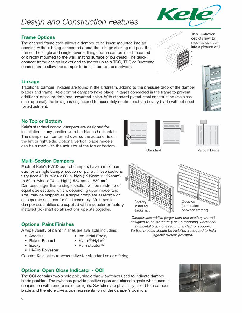
Damper assemblies (larger than one section) are not designed to be structurally self-supporting. Additional
horizontal bracing is recommended for support. Vertical bracing should be installed if required to hold
against system pressure.
Multi-Section DampersEach of Kele’s KVCD control dampers have a maximum size for a single damper section or panel. These sections vary from 48 in. wide x 60 in. high (1219mm x 1524mm) to 60 in. wide x 74 in. high (1524mm x 1880mm).Dampers larger than a single section will be made up of equal size sections which, depending upon model and size, may be shipped as a single complete assembly or as separate sections for field assembly. Multi-section damper assemblies are supplied with a coupler or factory installed jackshaft so all sections operate together.
Optional Paint FinishesA wide variety of paint finishes are available including:
• Anodize • Industrial Epoxy• Baked Enamel • Kynar®/Hylar®
• Epoxy • Permatector™• Hi-Pro Polyester
Contact Kele sales representative for standard color offering.
Optional Open Close Indicator - OCIThe OCI contains two single pole, single throw switches used to indicate damper blade position. The switches provide positive open and closed signals when used in conjunction with remote indicator lights. Switches are physically linked to a damper blade and therefore give a true representation of the damper’s position.
LinkageTraditional damper linkages are found in the airstream, adding to the pressure drop of the damper blades and frame. Kele control dampers have blade linkages concealed in the frame to prevent additional pressure drop and unwanted noise. With standard plated steel construction (stainless steel optional), the linkage is engineered to accurately control each and every blade without need for adjustment.
Frame OptionsThe channel frame style allows a damper to be insert mounted into an opening without being concerned about the linkage sticking out past the frame. The single and single reverse flange frame can be insert mounted or directly mounted to the wall, mating surface or bulkhead. The quick connect frame design is extruded to match up to a TDC, TDF, or Ductmate connection to allow the damper to be cleated to the ductwork.
This illustration depicts how to mount a damper into a plenum wall.
No Top or BottomKele’s standard control dampers are designed for installation in any position with the blades horizontal. The damper can be turned over so the actuator is on the left or right side. Optional vertical blade models can be turned with the actuator at the top or bottom.
Vertical BladeStandard
Factory Installed Jackshaft
Coupled (concealed between frames)
7
Actuator Options
Pneumatic
Manual Hand Quadrant
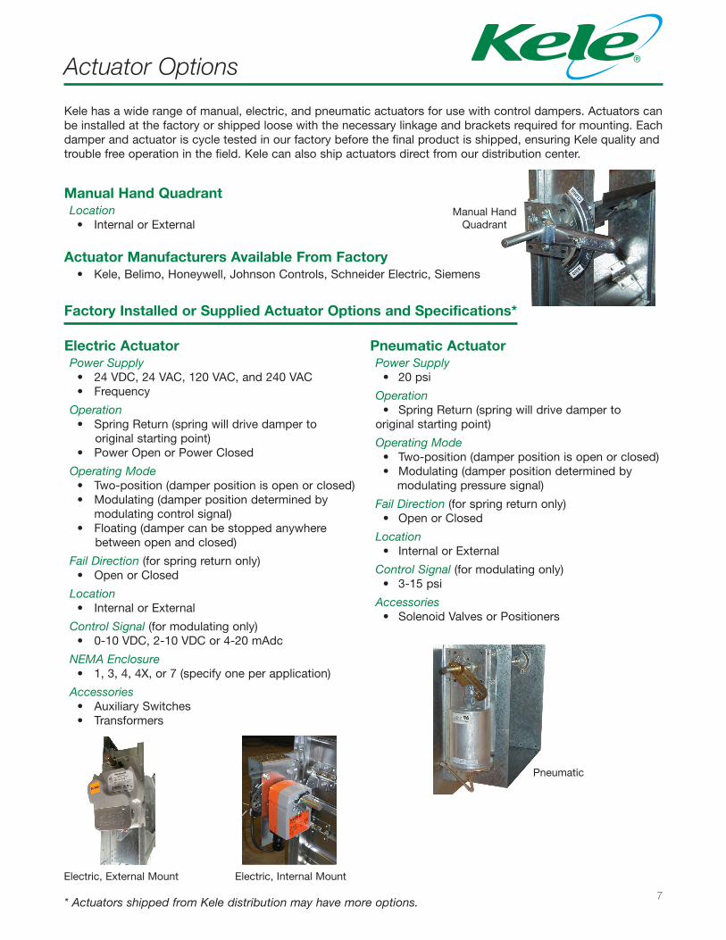
Manual Hand QuadrantLocation
• Internal or External
Actuator Manufacturers Available From Factory• Kele, Belimo, Honeywell, Johnson Controls, Schneider Electric, Siemens
Factory Installed or Supplied Actuator Options and Specifications*
Electric, External Mount Electric, Internal Mount
Kele has a wide range of manual, electric, and pneumatic actuators for use with control dampers. Actuators can be installed at the factory or shipped loose with the necessary linkage and brackets required for mounting. Each damper and actuator is cycle tested in our factory before the final product is shipped, ensuring Kele quality and trouble free operation in the field. Kele can also ship actuators direct from our distribution center.
Electric ActuatorPower Supply
• 24 VDC, 24 VAC, 120 VAC, and 240 VAC• Frequency
Operation• Spring Return (spring will drive damper to
original starting point)• Power Open or Power Closed
Operating Mode• Two-position (damper position is open or closed)• Modulating (damper position determined by
modulating control signal)• Floating (damper can be stopped anywhere
between open and closed)
Fail Direction (for spring return only)• Open or Closed
Location• Internal or External
Control Signal (for modulating only)• 0-10 VDC, 2-10 VDC or 4-20 mAdc
NEMA Enclosure • 1, 3, 4, 4X, or 7 (specify one per application)
Accessories• Auxiliary Switches• Transformers
Pneumatic ActuatorPower Supply
• 20 psi
Operation• Spring Return (spring will drive damper to
original starting point)
Operating Mode• Two-position (damper position is open or closed)• Modulating (damper position determined by
modulating pressure signal)
Fail Direction (for spring return only)• Open or Closed
Location• Internal or External
Control Signal (for modulating only)• 3-15 psi
Accessories• Solenoid Valves or Positioners
* Actuators shipped from Kele distribution may have more options.
8
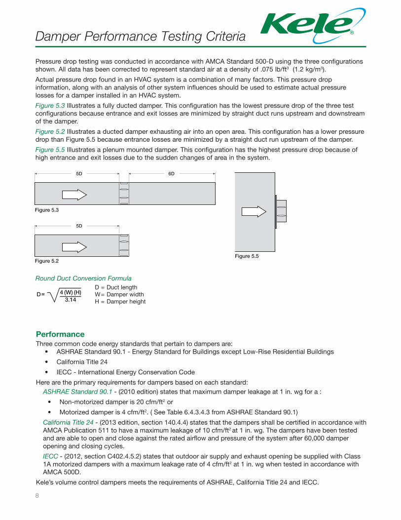
Pressure drop testing was conducted in accordance with AMCA Standard 500-D using the three configurations shown. All data has been corrected to represent standard air at a density of .075 lb/ft3 (1.2 kg/m3).
Actual pressure drop found in an HVAC system is a combination of many factors. This pressure drop information, along with an analysis of other system influences should be used to estimate actual pressure losses for a damper installed in an HVAC system.
Figure 5.3 Illustrates a fully ducted damper. This configuration has the lowest pressure drop of the three test configurations because entrance and exit losses are minimized by straight duct runs upstream and downstream of the damper.
Figure 5.2 Illustrates a ducted damper exhausting air into an open area. This configuration has a lower pressure drop than Figure 5.5 because entrance losses are minimized by a straight duct run upstream of the damper.
Figure 5.5 Illustrates a plenum mounted damper. This configuration has the highest pressure drop because of high entrance and exit losses due to the sudden changes of area in the system.
Damper Performance Testing Criteria
PerformanceThree common code energy standards that pertain to dampers are:
• ASHRAE Standard 90.1 - Energy Standard for Buildings except Low-Rise Residential Buildings
• California Title 24
• IECC - International Energy Conservation Code
Here are the primary requirements for dampers based on each standard: ASHRAE Standard 90.1 - (2010 edition) states that maximum damper leakage at 1 in. wg for a :
• Non-motorized damper is 20 cfm/ft2 or
• Motorized damper is 4 cfm/ft2. ( See Table 6.4.3.4.3 from ASHRAE Standard 90.1)
California Title 24 - (2013 edition, section 140.4.4) states that the dampers shall be certified in accordance with AMCA Publication 511 to have a maximum leakage of 10 cfm/ft2 at 1 in. wg. The dampers have been tested and are able to open and close against the rated airflow and pressure of the system after 60,000 damper opening and closing cycles.
IECC - (2012, section C402.4.5.2) states that outdoor air supply and exhaust opening be supplied with Class 1A motorized dampers with a maximum leakage rate of 4 cfm/ft2 at 1 in. wg when tested in accordance with AMCA 500D.
Kele’s volume control dampers meets the requirements of ASHRAE, California Title 24 and IECC.
5D 6D
Figure 5.3
Figure 5.2
5D
Figure 5.5
4 (W) (H)D=3.14
5D 6D
Figure 5.3
Figure 5.2
5D
Figure 5.5
4 (W) (H)D=3.14
D = Duct lengthW = Damper widthH = Damper height
5D 6D
Figure 5.3
Figure 5.2
5D
Figure 5.5
4 (W) (H)D=3.14
Round Duct Conversion Formula
9
Air Leakage
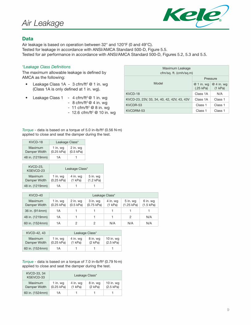
*Leakage Class DefinitionsThe maximum allowable leakage is defined by AMCA as the following:
• Leakage Class 1A - 3 cfm/ft2 @ 1 in. wg(Class 1A is only defined at 1 in. wg).
• Leakage Class 1 - 4 cfm/ft2 @ 1 in. wg - 8 cfm/ft2 @ 4 in. wg - 11 cfm/ft2 @ 8 in. wg - 12.6 cfm/ft2 @ 10 in. wg
Maximum Leakagecfm/sq. ft. (cmh/sq.m)
ModelPressure
@ 1 in. wg(.25 kPa)
@ 4 in. wg(1 kPa)
KVCD-18 Class 1A N/A
KVCD-23, 23V, 33, 34, 40, 42, 42V, 43, 43V Class 1A Class 1
KVCDR-53 Class 1 Class 1
KVCDRM-53 Class 1 Class 1
KVCD-33, 34 KSEVCD-33
Leakage Class*
Maximum Damper Width
1 in. wg (0.25 kPa)
4 in. wg(1 kPa)
8 in. wg(2 kPa)
10 in. wg(2.5 kPa)
60 in. (1524mm) 1A 1 1 1
Torque - data is based on a torque of 7.0 in-lb/ft² (0.79 N·m) applied to close and seat the damper during the test.
KVCD-18 Leakage Class*
Maximum Damper Width
1 in. wg (0.25 kPa)
2 in. wg(0.5 kPa)
48 in. (1219mm) 1A 1
KVCD-23, KSEVCD-23
Leakage Class*
Maximum Damper Width
1 in. wg (0.25 kPa)
4 in. wg(1 kPa)
5 in. wg(1.2 kPa)
48 in. (1219mm) 1A 1 1
KVCD-42, 43 Leakage Class*
Maximum Damper Width
1 in. wg (0.25 kPa)
4 in. wg(1 kPa)
8 in. wg(2 kPa)
10 in. wg(2.5 kPa)
60 in. (1524mm) 1A 1 1 1
Torque - data is based on a torque of 5.0 in-lb/ft² (0.56 N·m) applied to close and seat the damper during the test.
KVCD-40 Leakage Class*
Maximum Damper Width
1 in. wg (0.25 kPa)
2 in. wg (0.5 kPa)
3 in. wg (0.75 kPa)
4 in. wg(1 kPa)
5 in. wg(1.25 kPa)
6 in. wg(1.5 kPa)
36 in. (914mm) 1A 1 1 1 1 1
48 in. (1219mm) 1A 1 1 1 2 N/A
60 in. (1524mm) 1A 2 2 N/A N/A N/A
DataAir leakage is based on operation between 32° and 120°F (0 and 49°C).Tested for leakage in accordance with ANSI/AMCA Standard 500-D, Figure 5.5.Tested for air performance in accordance with ANSI/AMCA Standard 500-D, Figures 5.2, 5.3 and 5.5.
10
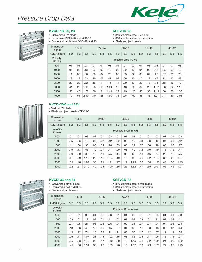
Pressure Drop Data
Dimensioninches
12x12 24x24 36x36 12x48 48x12
AMCA figure 5.2 5.3 5.5 5.2 5.3 5.5 5.2 5.3 5.5 5.2 5.3 5.5 5.2 5.3 5.5
Velocity (ft/min)
Pressure Drop in. wg
500 .01 .01 .03 .01 .01 .03 .01 .01 .02 .01 .01 .03 .01 .01 .03
1000 .05 .03 .13 .03 .02 .12 .02 .02 .10 .04 .03 .12 .03 .03 .12
1500 .11 .08 .30 .06 .04 .26 .05 .03 .22 .08 .07 .27 .07 .06 .28
2000 .19 .13 .53 .10 .07 .47 .09 .06 .40 .15 .12 .47 .12 .10 .49
2500 .29 .20 .82 .16 .11 .75 .14 .09 .62 .22 .18 .75 .18 .16 .77
3000 .41 .29 1.19 .23 .16 1.04 .19 .13 .90 .32 .26 1.07 .26 .22 1.12
3500 .55 .40 1.62 .30 .21 1.41 .27 .19 1.23 .43 .36 1.45 .36 .30 1.53
4000 .72 .51 2.10 .40 .28 1.90 .35 .25 1.62 .56 .46 1.91 .47 .39 2.01
KVCD-18, 20, 23• Galvanized 3V blade• Economic KVCD-20 and VCD-18• Blade and jamb seals VCD-18 and 23
KSEVCD-23• 316 stainless steel 3V blade• 316 stainless steel construction• Blade and jamb seals
Dimensioninches
12x12 24x24 36x36 12x48 48x12
AMCA figure 5.2 5.3 5.5 5.2 5.3 5.5 5.2 5.3 5.5 5.2 5.3 5.5 5.2 5.3 5.5
Velocity (ft/min)
Pressure Drop in. wg
500 .01 .01 .03 .01 .01 .03 .01 .01 .02 .01 .01 .03 .01 .01 .03
1000 .05 .03 .13 .03 .02 .12 .02 .02 .10 .03 .03 .12 .04 .03 .12
1500 .11 .08 .30 .06 .04 .26 .05 .03 .22 .07 .06 .28 .08 .07 .27
2000 .19 .13 .53 .10 .07 .47 .09 .06 .40 .12 .10 .49 .15 .12 .47
2500 .29 .20 .82 .16 .11 .75 .14 .09 .62 .18 .16 .77 .22 .18 .75
3000 .41 .29 1.19 .23 .16 1.04 .19 .13 .90 .26 .22 1.12 .32 .26 1.07
3500 .55 .40 1.62 .30 .21 1.41 .27 .19 1.23 .36 .30 1.53 .43 .36 1.45
4000 .72 .51 2.10 .40 .28 1.90 .35 .25 1.62 .47 .39 2.01 .56 .46 1.91
KVCD-20V and 23V• Vertical 3V blade• Blade and jamb seals VCD-23V
Dimensioninches
12x12 24x24 36x36 12x48 48x12
AMCA figure 5.2 5.3 5.5 5.2 5.3 5.5 5.2 5.3 5.5 5.2 5.3 5.5 .5.2 5.3 5.5
Velocity (ft/min)
Pressure Drop in. wg
500 .01 .01 .03 .01 .01 .03 .01 .01 .02 .01 .01 .03 .01 .01 .03
1000 .03 .02 .12 .03 .01 .11 .02 .01 .09 .03 .02 .11 .02 .02 .11
1500 .07 .05 .27 .06 .03 .26 .04 .02 .21 .07 .04 .24 .04 .04 .24
2000 .13 .08 .48 .10 .05 .45 .07 .04 .38 .11 .08 .43 .08 .07 .44
2500 .19 .12 .74 .15 .09 .71 .11 .06 .58 .17 .12 .67 .12 .11 .68
3000 .26 .17 1.07 .21 .13 1.02 .15 .08 .85 .23 .17 .96 .16 .15 .97
3500 .35 .23 1.46 .28 .17 1.40 .20 .12 1.15 .31 .22 1.31 .21 .20 1.32
4000 .45 .30 1.91 .36 .22 1.89 .26 .15 1.52 .39 .29 1.71 .27 .25 1.73
KVCD-33 and 34• Galvanized airfoil blade• Insulated airfoil KVCD-34• Blade and jamb seals
KSEVCD-33• 316 stainless steel airfoil blade• 316 stainless steel construction• Blade and jamb seals
11
Pressure Drop Data
Dimensioninches
12x12 24x24 36x36 12x48 48x12
AMCA figure 5.2 5.3 5.5 5.2 5.3 5.5 5.2 5.3 5.5 5.2 5.3 5.5 5.2 5.3 5.5
Velocity (ft/min)
Pressure Drop in. wg
500 .01 .01 .03 .01 .01 .03 .01 .01 .02 .01 .01 .03 .01 .01 .03
1000 .03 .02 .12 .03 .01 .11 .02 .01 .09 .02 .02 .11 .03 .02 .11
1500 .07 .05 .27 .06 .03 .26 .04 .02 .21 .04 .04 .24 .07 .04 .24
2000 .13 .08 .48 .10 .05 .45 .07 .04 .38 .08 .07 .44 .11 .08 .43
2500 .19 .12 .74 .15 .09 .71 .11 .06 .58 .12 .11 .68 .17 .12 .67
3000 .26 .17 1.07 .21 .13 1.02 .15 .08 .85 .16 .15 .97 .23 .17 .96
3500 .35 .23 1.46 .28 .17 1.40 .20 .12 1.15 .21 .20 1.32 .31 .22 1.31
4000 .45 .30 1.91 .36 .22 1.89 .26 .15 1.52 .27 .25 1.73 .39 .29 1.71
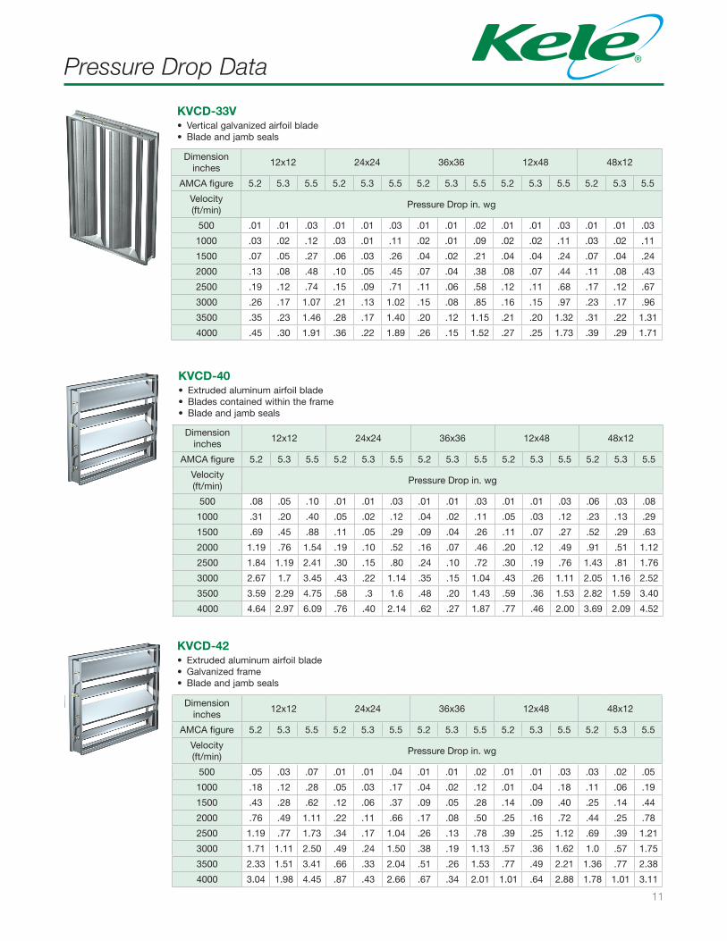
KVCD-33V• Vertical galvanized airfoil blade• Blade and jamb seals
Dimensioninches
12x12 24x24 36x36 12x48 48x12
AMCA figure 5.2 5.3 5.5 5.2 5.3 5.5 5.2 5.3 5.5 5.2 5.3 5.5 5.2 5.3 5.5
Velocity (ft/min)
Pressure Drop in. wg
500 .08 .05 .10 .01 .01 .03 .01 .01 .03 .01 .01 .03 .06 .03 .08
1000 .31 .20 .40 .05 .02 .12 .04 .02 .11 .05 .03 .12 .23 .13 .29
1500 .69 .45 .88 .11 .05 .29 .09 .04 .26 .11 .07 .27 .52 .29 .63
2000 1.19 .76 1.54 .19 .10 .52 .16 .07 .46 .20 .12 .49 .91 .51 1.12
2500 1.84 1.19 2.41 .30 .15 .80 .24 .10 .72 .30 .19 .76 1.43 .81 1.76
3000 2.67 1.7 3.45 .43 .22 1.14 .35 .15 1.04 .43 .26 1.11 2.05 1.16 2.52
3500 3.59 2.29 4.75 .58 .3 1.6 .48 .20 1.43 .59 .36 1.53 2.82 1.59 3.40
4000 4.64 2.97 6.09 .76 .40 2.14 .62 .27 1.87 .77 .46 2.00 3.69 2.09 4.52
KVCD-40• Extruded aluminum airfoil blade• Blades contained within the frame• Blade and jamb seals
Dimensioninches
12x12 24x24 36x36 12x48 48x12
AMCA figure 5.2 5.3 5.5 5.2 5.3 5.5 5.2 5.3 5.5 5.2 5.3 5.5 5.2 5.3 5.5
Velocity (ft/min)
Pressure Drop in. wg
500 .05 .03 .07 .01 .01 .04 .01 .01 .02 .01 .01 .03 .03 .02 .05
1000 .18 .12 .28 .05 .03 .17 .04 .02 .12 .01 .04 .18 .11 .06 .19
1500 .43 .28 .62 .12 .06 .37 .09 .05 .28 .14 .09 .40 .25 .14 .44
2000 .76 .49 1.11 .22 .11 .66 .17 .08 .50 .25 .16 .72 .44 .25 .78
2500 1.19 .77 1.73 .34 .17 1.04 .26 .13 .78 .39 .25 1.12 .69 .39 1.21
3000 1.71 1.11 2.50 .49 .24 1.50 .38 .19 1.13 .57 .36 1.62 1.0 .57 1.75
3500 2.33 1.51 3.41 .66 .33 2.04 .51 .26 1.53 .77 .49 2.21 1.36 .77 2.38
4000 3.04 1.98 4.45 .87 .43 2.66 .67 .34 2.01 1.01 .64 2.88 1.78 1.01 3.11
KVCD-42• Extruded aluminum airfoil blade• Galvanized frame• Blade and jamb seals
12
Pressure Drop Data
Dimensioninches
12x12 24x24 36x36 12x48 48x12
AMCA figure 5.2 5.3 5.5 5.2 5.3 5.5 5.2 5.3 5.5 5.2 5.3 5.5 5.2 5.3 5.5
Velocity (ft/min)
Pressure Drop in. wg
500 .01 .01 .04 .01 .01 .03 .01 .01 .03 .01 .01 .03 .01 .01 .03
1000 .06 .03 .14 .04 .02 .12 .03 .01 .10 .04 .03 .11 .03 .02 .11
1500 .13 .07 .31 .10 .04 .27 .06 .02 .22 .10 .06 .25 .06 .04 .26
2000 .23 .14 .55 .18 .08 .48 .12 .04 .39 .17 .11 .46 .10 .08 .46
2500 .35 .21 .86 .28 .13 .75 .18 .06 .61 .26 .17 .72 .16 .12 .72
3000 .50 .29 1.23 .40 .19 1.07 .26 .09 .87 .38 .25 1.05 .23 .18 1.02
3500 .68 .39 1.67 .54 .26 1.47 .35 .13 1.19 .52 .34 1.43 .30 .24 1.40
4000 .88 .51 2.19 .70 .34 1.91 .46 .17 1.56 .68 .45 1.87 .39 .31 1.83
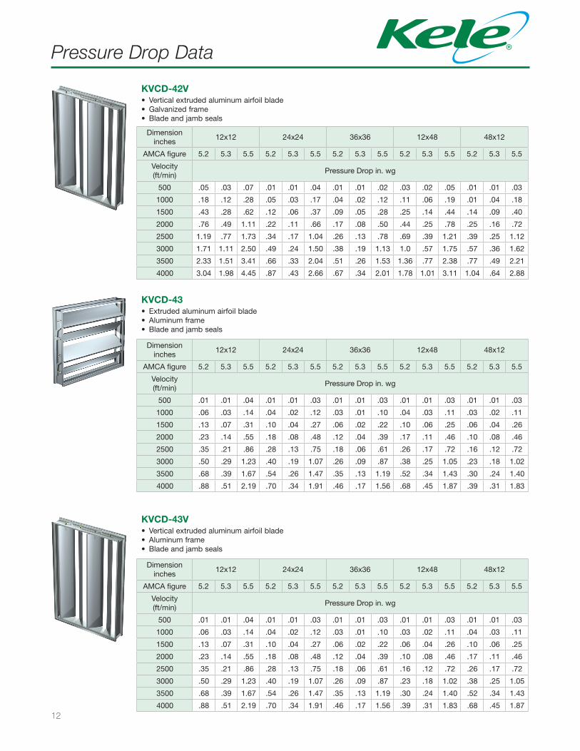
KVCD-43• Extruded aluminum airfoil blade• Aluminum frame• Blade and jamb seals
Dimensioninches
12x12 24x24 36x36 12x48 48x12
AMCA figure 5.2 5.3 5.5 5.2 5.3 5.5 5.2 5.3 5.5 5.2 5.3 5.5 5.2 5.3 5.5
Velocity (ft/min)
Pressure Drop in. wg
500 .05 .03 .07 .01 .01 .04 .01 .01 .02 .03 .02 .05 .01 .01 .03
1000 .18 .12 .28 .05 .03 .17 .04 .02 .12 .11 .06 .19 .01 .04 .18
1500 .43 .28 .62 .12 .06 .37 .09 .05 .28 .25 .14 .44 .14 .09 .40
2000 .76 .49 1.11 .22 .11 .66 .17 .08 .50 .44 .25 .78 .25 .16 .72
2500 1.19 .77 1.73 .34 .17 1.04 .26 .13 .78 .69 .39 1.21 .39 .25 1.12
3000 1.71 1.11 2.50 .49 .24 1.50 .38 .19 1.13 1.0 .57 1.75 .57 .36 1.62
3500 2.33 1.51 3.41 .66 .33 2.04 .51 .26 1.53 1.36 .77 2.38 .77 .49 2.21
4000 3.04 1.98 4.45 .87 .43 2.66 .67 .34 2.01 1.78 1.01 3.11 1.04 .64 2.88
KVCD-42V• Vertical extruded aluminum airfoil blade• Galvanized frame• Blade and jamb seals
KVCD-43V• Vertical extruded aluminum airfoil blade• Aluminum frame• Blade and jamb seals
Dimensioninches
12x12 24x24 36x36 12x48 48x12
AMCA figure 5.2 5.3 5.5 5.2 5.3 5.5 5.2 5.3 5.5 5.2 5.3 5.5 5.2 5.3 5.5
Velocity (ft/min)
Pressure Drop in. wg
500 .01 .01 .04 .01 .01 .03 .01 .01 .03 .01 .01 .03 .01 .01 .03
1000 .06 .03 .14 .04 .02 .12 .03 .01 .10 .03 .02 .11 .04 .03 .11
1500 .13 .07 .31 .10 .04 .27 .06 .02 .22 .06 .04 .26 .10 .06 .25
2000 .23 .14 .55 .18 .08 .48 .12 .04 .39 .10 .08 .46 .17 .11 .46
2500 .35 .21 .86 .28 .13 .75 .18 .06 .61 .16 .12 .72 .26 .17 .72
3000 .50 .29 1.23 .40 .19 1.07 .26 .09 .87 .23 .18 1.02 .38 .25 1.05
3500 .68 .39 1.67 .54 .26 1.47 .35 .13 1.19 .30 .24 1.40 .52 .34 1.43
4000 .88 .51 2.19 .70 .34 1.91 .46 .17 1.56 .39 .31 1.83 .68 .45 1.87
13
Pressure Drop Data
Dimensioninches
12 24
AMCA figure 5.2 5.3 5.5 5.2 5.3 5.5
Velocity (ft/min)
Pressure Drop in. wg
500 .01 .01 .02 .01 .01 .02
1000 .06 .02 .10 .04 .01 .09
1500 .13 .05 .22 .08 .03 .20
2000 .23 .08 .38 .15 .06 .36
2500 .37 .13 .60 .23 .09 .56
3000 .53 .19 .86 .33 .13 .81
Dimensioninches
12 24 36
AMCA figure 5.2 5.3 5.5 5.2 5.3 5.5 5.2 5.3 5.5
Velocity (ft/min)
Pressure Drop in. wg
500 .04 .03 .05 .03 .02 .04 .05 .05 .06
1000 .15 .11 .19 .13 .10 .15 .19 .20 .25
1500 .33 .25 .42 .29 .21 .33 .42 .44 .57
2000 .59 .45 .75 .51 .38 .59 .75 .79 1.01
2500 .93 .70 1.18 .79 .60 .92 1.18 1.23 1.58
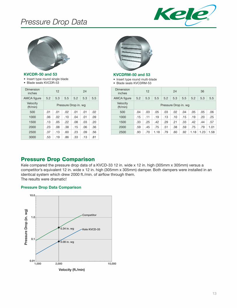
KVCDR-50 and 53• Insert type round single blade• Blade seals KVCDR-53
KVCDRM-50 and 53• Insert type round multi-blade• Blade seals KVCDRM-53
Pressure Drop ComparisonKele compared the pressure drop data of a KVCD-33 12 in. wide x 12 in. high (305mm x 305mm) versus a competitor’s equivalent 12 in. wide x 12 in. high (305mm x 305mm) damper. Both dampers were installed in an identical system which drew 2000 ft./min. of airflow through them. The results were dramatic!
Pressure Drop Data Comparison
0.01
0.1
1.0
10.0
Pre
ssur
e D
rop
(in.
wg
)
Velocity (ft./min)
Competitor
Kele KVCD-33
0.08 in. wg
0.34 in. wg
1,000 2,000 10,000
14
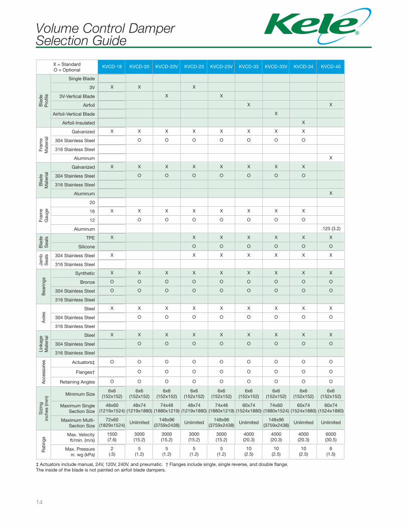
Volume Control Damper Selection Guide
X = StandardO = Optional
KVCD-18 KVCD-20 KVCD-20V KVCD-23 KVCD-23V KVCD-33 KVCD-33V KVCD-34 KVCD-40
Bla
de
Pro
file
Single Blade
3V X X X
3V-Vertical Blade X X
Airfoil X X
Airfoil-Vertical Blade X
Airfoil-Insulated X
Fram
e M
ater
ial
Galvanized X X X X X X X X
304 Stainless Steel O O O O O O O
316 Stainless Steel
Aluminum X
Bla
de
Mat
eria
l
Galvanized X X X X X X X X
304 Stainless Steel O O O O O O O
316 Stainless Steel
Aluminum X
Fram
eG
auge
20
16 X X X X X X X X
12 O O O O O O O
Aluminum .125 (3.2)
Bla
de
Sea
ls TPE X X X X X X X
Silicone O O O O O O
Jam
bS
eals 304 Stainless Steel X X X X X X X
316 Stainless Steel
Bea
rings
Synthetic X X X X X X X X X
Bronze O O O O O O O O O
304 Stainless Steel O O O O O O O O O
316 Stainless Steel
Axl
es
Steel X X X X X X X X X
304 Stainless Steel O O O O O O O O
316 Stainless Steel
Link
age
Mat
eria
l Steel X X X X X X X X X
304 Stainless Steel O O O O O O O O
316 Stainless Steel
Acc
esso
ries Actuators‡ O O O O O O O O O
Flanges† O O O O O O O O
Retaining Angles O O O O O O O O O
Siz
ing
inch
es (m
m) Minimum Size
6x6(152x152)
6x6(152x152)
6x6(152x152)
6x6(152x152)
6x6(152x152)
6x6(152x152)
6x6(152x152)
6x6(152x152)
6x6(152x152)
Maximum Single Section Size
48x60(1219x1524)
48x74(1219x1880)
74x48(1880x1219)
48x74(1219x1880)
74x48(1880x1219)
60x74(1524x1880)
74x60(1880x1524)
60x74(1524x1880)
60x74(1524x1880)
Maximum Multi-Section Size
72x60(1829x1524)
Unlimited148x96
(3759x2438)Unlimited
148x96(3759x2438)
Unlimited148x96
(3759x2438)Unlimited Unlimited
Rat
ings
Max. Velocityft/min. (m/s)
1500(7.6)
3000(15.2)
3000(15.2)
3000(15.2)
3000(15.2)
4000(20.3)
4000(20.3)
4000(20.3)
6000(30.5)
Max. Pressurein. wg (kPa)
2(.5)
5(1.2)
5(1.2)
5(1.2)
5(1.2)
10(2.5)
10(2.5)
10(2.5)
6(1.5)
‡ Actuators include manual, 24V, 120V, 240V, and pneumatic. † Flanges include single, single reverse, and double flange. The inside of the blade is not painted on airfoil blade dampers.
15
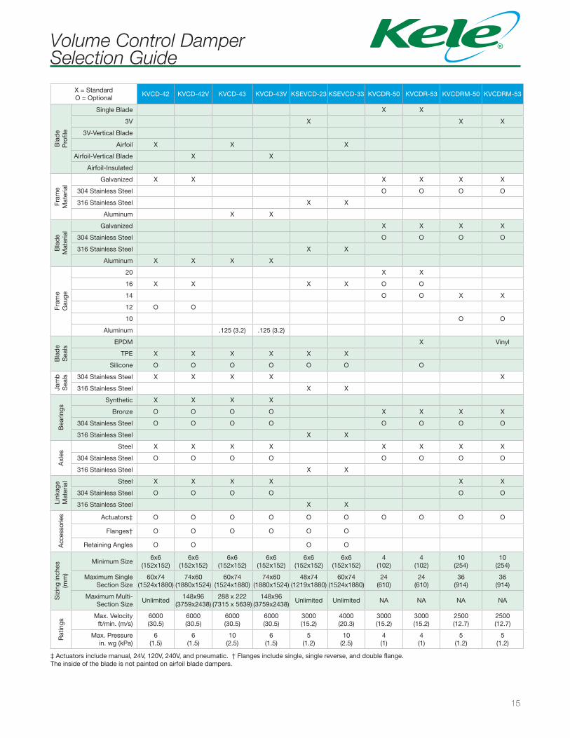
Volume Control Damper Selection Guide
‡ Actuators include manual, 24V, 120V, 240V, and pneumatic. † Flanges include single, single reverse, and double flange. The inside of the blade is not painted on airfoil blade dampers.
X = StandardO = Optional
KVCD-42 KVCD-42V KVCD-43 KVCD-43V KSEVCD-23 KSEVCD-33 KVCDR-50 KVCDR-53 KVCDRM-50 KVCDRM-53
Bla
de
Pro
file
Single Blade X X
3V X X X
3V-Vertical Blade
Airfoil X X X
Airfoil-Vertical Blade X X
Airfoil-Insulated
Fram
e M
ater
ial
Galvanized X X X X X X
304 Stainless Steel O O O O
316 Stainless Steel X X
Aluminum X X
Bla
de
Mat
eria
l
Galvanized X X X X
304 Stainless Steel O O O O
316 Stainless Steel X X
Aluminum X X X X
Fram
e G
auge
20 X X
16 X X X X O O
14 O O X X
12 O O
10 O O
Aluminum .125 (3.2) .125 (3.2)
Bla
de
Sea
ls
EPDM X Vinyl
TPE X X X X X X
Silicone O O O O O O O
Jam
bS
eals 304 Stainless Steel X X X X X
316 Stainless Steel X X
Bea
rings
Synthetic X X X X
Bronze O O O O X X X X
304 Stainless Steel O O O O O O O O
316 Stainless Steel X X
Axl
es
Steel X X X X X X X X
304 Stainless Steel O O O O O O O O
316 Stainless Steel X X
Link
age
Mat
eria
l Steel X X X X X X
304 Stainless Steel O O O O O O
316 Stainless Steel X X
Acc
esso
ries Actuators‡ O O O O O O O O O O
Flanges† O O O O O O
Retaining Angles O O O O
Siz
ing
inch
es(m
m)
Minimum Size6x6
(152x152)6x6
(152x152)6x6
(152x152)6x6
(152x152)6x6
(152x152)6x6
(152x152)4
(102)4
(102)10
(254)10
(254)
Maximum Single Section Size
60x74(1524x1880)
74x60(1880x1524)
60x74(1524x1880)
74x60(1880x1524)
48x74(1219x1880)
60x74(1524x1880)
24(610)
24(610)
36(914)
36(914)
Maximum Multi-Section Size
Unlimited148x96
(3759x2438)288 x 222
(7315 x 5639)148x96
(3759x2438)Unlimited Unlimited NA NA NA NA
Rat
ings
Max. Velocityft/min. (m/s)
6000(30.5)
6000(30.5)
6000(30.5)
6000(30.5)
3000(15.2)
4000(20.3)
3000(15.2)
3000(15.2)
2500(12.7)
2500(12.7)
Max. Pressurein. wg (kPa)
6(1.5)
6(1.5)
10(2.5)
6(1.5)
5(1.2)
10(2.5)
4(1)
4(1)
5(1.2)
5(1.2)
3300 BROTHER BLVD | MEMPHIS, TN 38133 | 888.397.KELE (5353) | www.kele.com
© 2014 Kele, Inc. All Rights Reserved. The Kele name and logo are registered trademarks of Kele, Inc.
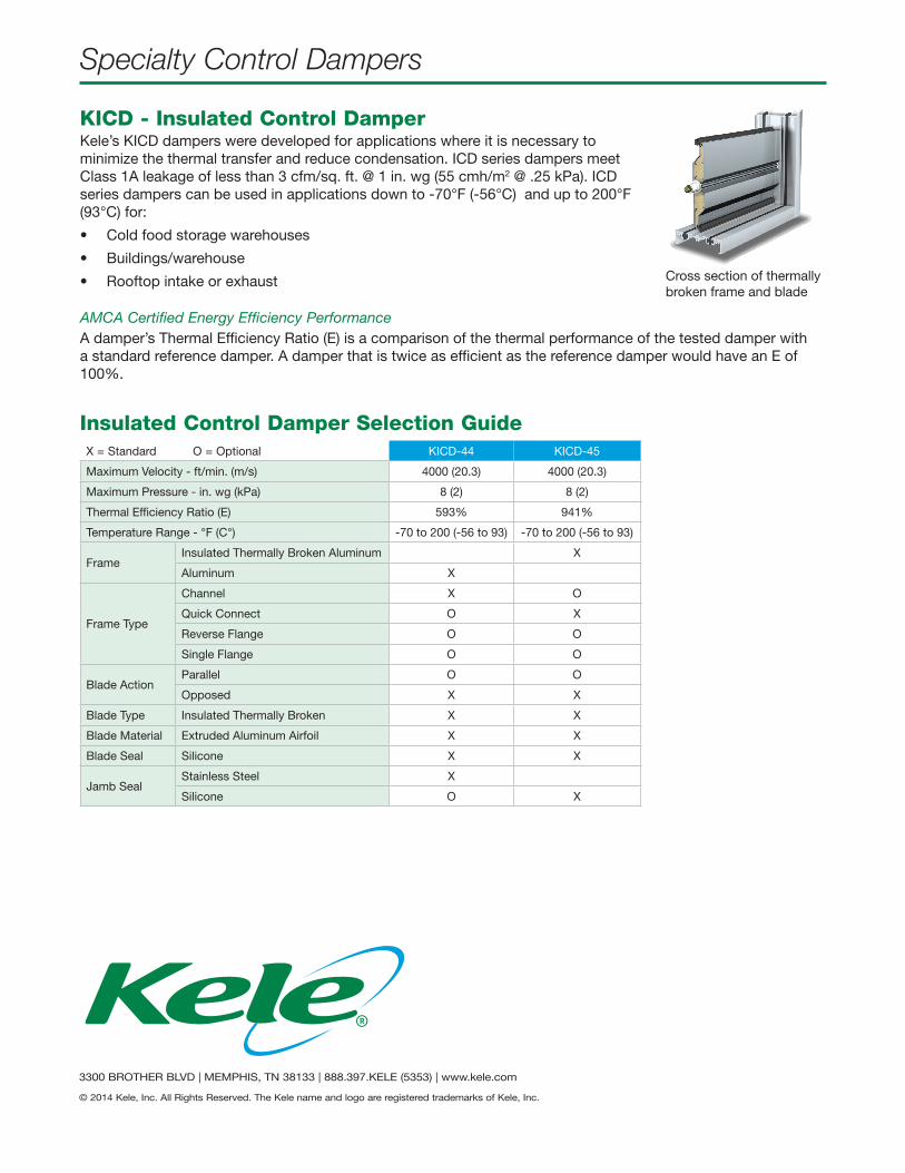
KICD - Insulated Control DamperKele’s KICD dampers were developed for applications where it is necessary to minimize the thermal transfer and reduce condensation. ICD series dampers meet Class 1A leakage of less than 3 cfm/sq. ft. @ 1 in. wg (55 cmh/m2 @ .25 kPa). ICD series dampers can be used in applications down to -70°F (-56°C) and up to 200°F (93°C) for:
• Cold food storage warehouses
• Buildings/warehouse
• Rooftop intake or exhaust
AMCA Certified Energy Efficiency PerformanceA damper’s Thermal Efficiency Ratio (E) is a comparison of the thermal performance of the tested damper with a standard reference damper. A damper that is twice as efficient as the reference damper would have an E of 100%.
Cross section of thermally broken frame and blade
X = Standard O = Optional KICD-44 KICD-45
Maximum Velocity - ft/min. (m/s) 4000 (20.3) 4000 (20.3)
Maximum Pressure - in. wg (kPa) 8 (2) 8 (2)
Thermal Efficiency Ratio (E) 593% 941%
Temperature Range - °F (C°) -70 to 200 (-56 to 93) -70 to 200 (-56 to 93)
FrameInsulated Thermally Broken Aluminum X
Aluminum X
Frame Type
Channel X O
Quick Connect O X
Reverse Flange O O
Single Flange O O
Blade ActionParallel O O
Opposed X X
Blade Type Insulated Thermally Broken X X
Blade Material Extruded Aluminum Airfoil X X
Blade Seal Silicone X X
Jamb SealStainless Steel X
Silicone O X
Insulated Control Damper Selection Guide
Specialty Control Dampers