Embed Size (px)
Citation preview
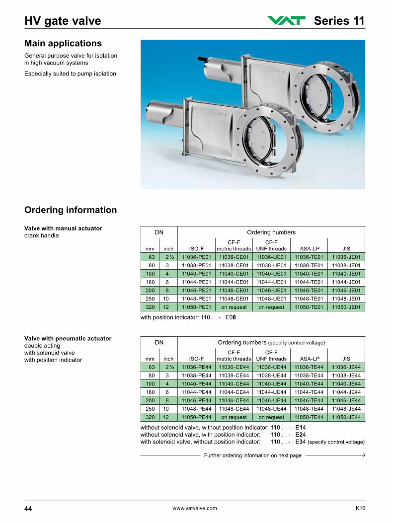
Main applicationsGeneral purpose valve for isolation in high vacuum systems
Especially suited to pump isolation
DN Ordering numbers
mm inch ISO-FCF-F
metric threadsCF-F
UNF threads ASA-LP JIS 63 2 ½ 11036-PE01 11036-CE01 11036-UE01 11036-TE01 11036-JE01 80 3 11038-PE01 11038-CE01 11038-UE01 11038-TE01 11038-JE01 100 4 11040-PE01 11040-CE01 11040-UE01 11040-TE01 11040-JE01 160 6 11044-PE01 11044-CE01 11044-UE01 11044-TE01 11044-JE01 200 8 11046-PE01 11046-CE01 11046-UE01 11046-TE01 11046-JE01 250 10 11048-PE01 11048-CE01 11048-UE01 11048-TE01 11048-JE01 320 12 11050-PE01 on request on request 11050-TE01 11050-JE01
DN Ordering numbers (specify control voltage)
mm inch ISO-FCF-F
metric threadsCF-F
UNF threads ASA-LP JIS 63 2 ½ 11036-PE44 11036-CE44 11036-UE44 11036-TE44 11036-JE44 80 3 11038-PE44 11038-CE44 11038-UE44 11038-TE44 11038-JE44 100 4 11040-PE44 11040-CE44 11040-UE44 11040-TE44 11040-JE44 160 6 11044-PE44 11044-CE44 11044-UE44 11044-TE44 11044-JE44 200 8 11046-PE44 11046-CE44 11046-UE44 11046-TE44 11046-JE44 250 10 11048-PE44 11048-CE44 11048-UE44 11048-TE44 11048-JE44 320 12 11050-PE44 on request on request 11050-TE44 11050-JE44
Ordering information
Valve with manual actuatorcrank handle
Valve with pneumatic actuatordouble actingwith solenoid valvewith position indicator
Further ordering information on next page
without solenoid valve, without position indicator: 110 . . - . E14without solenoid valve, with position indicator: 110 . . - . E24with solenoid valve, without position indicator: 110 . . - . E34 (specify control voltage)
with position indicator: 110 . . - . E08
44 www.vatvalve.com K16
HV gate valve Series 11
DN Ordering numbers (specify control voltage)
mm inch ISO-FCF-F
metric threadsCF-F
UNF threads ASA-LP JIS 63 2 ½ 11036-PE48 11036-CE48 11036-UE48 11036-TE48 11036-JE48 80 3 11038-PE48 11038-CE48 11038-UE48 11038-TE48 11038-JE48 100 4 11040-PE48 11040-CE48 11040-UE48 11040-TE48 11040-JE48 160 6 11044-PE48 11044-CE48 11044-UE48 11044-TE48 11044-JE48 200 8 11046-PE48 11046-CE48 11046-UE48 11046-TE48 11046-JE48 250 10 11048-PE48 11048-CE48 11048-UE48 11048-TE48 11048-JE48 320 12 11050-PE48 on request on request 11050-TE48 11050-JE48
without solenoid valve, with position indicator: 110 . . - . E28
Technical data
Continued Ordering information
Leak rate: valve body, valve seat < 1 · 10-9 mbar Is-1
Pressure range – DN 63 – 200 1 · 10-8 mbar to 1.6 bar (abs) – DN 250 – 320 1 · 10-8 mbar to 1.2 bar (abs)
Differential pressure on the gate –DN 63–200 ≤1.6bar –DN250–320 ≤1.2bar
Differentialpressureatopening ≤30mbar
Cyclesuntilfirstservice 200000
Temperature 1) –Valvebody ≤150°C –Manualandpneumaticactuator ≤ 80°C –Solenoidvalve ≤ 50°C –Positionindicator ≤ 50°C
Valve with 3-position pneumatic actuatordouble actingwith solenoid valvewith position indicator
1) Maximum values: depending on operating conditions and sealing materials
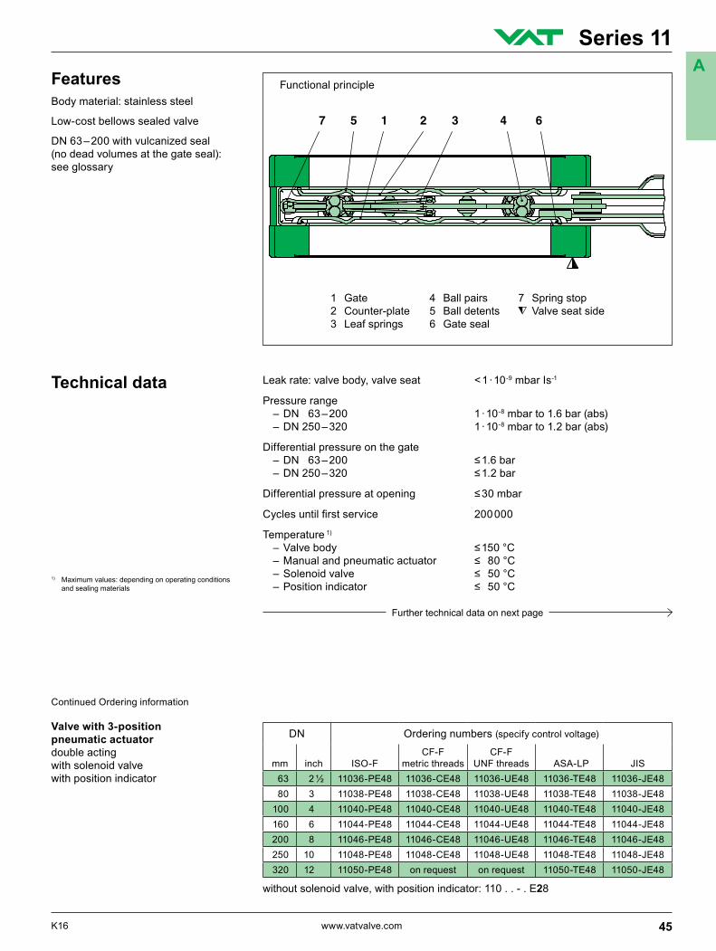
1 Gate 4 Ball pairs 7 Spring stop2 Counter-plate 5 Ball detents Valve seat side3 Leaf springs 6 Gate seal
Functional principleFeaturesBody material: stainless steel
Low-cost bellows sealed valve
DN 63 – 200 with vulcanized seal (no dead volumes at the gate seal): see glossary
Further technical data on next page
45K16 www.vatvalve.com
Series 11A
Continued Technical data
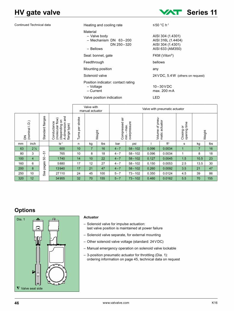
Valve seat side
Dia. 1 Actuator
– Solenoid valve for impulse actuation: last valve position is maintained at power failure
– Solenoid valve separate, for external mounting
– Other solenoid valve voltage (standard: 24 V DC)
– Manual emergency operation on solenoid valve lockable
– 3-position pneumatic actuator for throttling (Dia. 1): ordering information on page 45, technical data on request
Options
Heatingandcoolingrate ≤50°Ch-1
Material – Valve body AISI 304 (1.4301) – Mechanism DN 63 – 200 AISI 316L (1.4404) DN 250 – 320 AISI 304 (1.4301) – Bellows AISI 633 (AM350)
Seal: bonnet, gate FKM (Viton®)
Feedthrough bellows
Mounting position any
Solenoid valve 24 V DC, 5.4 W (others on request)
Position indicator: contact rating – Voltage 10 – 30 V DC – Current max. 200 m A
Valve position indication LED
Valve with manual actuator Valve with pneumatic actuator
DN
(n
omin
al I.
D.)
Standardflanges
Con
duct
ance
(molecularflow
)(d
epen
ding
on
A-d
imen
sion
and
flangetype)
Turn
s pe
r stro
ke
Wei
ght
Com
pres
sed
air
min
. – m
ax.
over
pres
sure
Volu
me
of p
neu-
mat
ic a
ctua
tor
Clo
sing
or
open
ing
time
Wei
ght
mm inch ls-1 n kg lbs bar psi l ft3 s kg lbs63 2 ½
Sse
pag
es 5
0 –
51
600 10 7 16 4 – 7 58 – 102 0.096 0.0034 1 7 1680 3 765 10 8 18 4 – 7 58 – 102 0.096 0.0034 1 8 18
100 4 1 740 14 10 22 4 – 7 58 – 102 0.127 0.0045 1.5 10.5 23160 6 5 880 17 12 27 4 – 7 58 – 102 0.150 0.0053 2.5 13.5 30200 8 13 940 17 21 47 4 – 7 58 – 102 0.260 0.0092 3.5 21 47250 10 27 110 24 45 100 5 – 7 73 – 102 0.350 0.0124 4.5 39 86320 12 34 955 32 70 155 5 – 7 73 – 102 0.460 0.0162 5.5 70 155
46 www.vatvalve.com K16
HV gate valve Series 11
Valve seat side
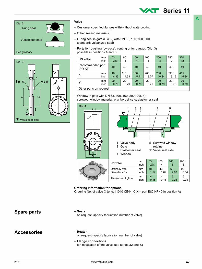
Valve
–Customerspecifiedflangeswith/withoutwatercooling
– Other sealing materials
– O-ring seal in gate (Dia. 2) with DN 63, 100, 160, 200 (standard: vulcanized seal)
– Ports for roughing (by-pass), venting or for gauges (Dia. 3), possible in positions A and B
Dia. 3
Dia. 2
– Seals on request (specify fabrication number of valve)
Spare parts
– Heater on request (specify fabrication number of valve)
– Flange connections for installation of the valve: see series 32 and 33
Accessories
DN valve mm inch
63 2 ½
80 3
100 4
160 6
200 8
250 10
320 12
Recommended port ISO-KF 40 40 40 40 40 40 40
X mm inch
110 4.33
110 4.33
150 5.91
205 8.07
260 10.24
335 13.19
415 16.34
Y mm inch
20 0.79
20 0.79
20 0.79
20 0.79
20 0.79
20 0.79
20 0.79
Other ports on request
O-ring seal
Vulcanized seal
See glossary
– Window in gate with DN 63, 100, 160, 200 (Dia. 4): screwed, window material: e. g. borosilicate, elastomer seal
Ordering information for options:Ordering No. of valve-X (e. g. 11040-CE44-X, X = port ISO-KF 40 in position A)
Dia. 4
1 Valve body 5 Screwed window 2 Gate retainer 3 Elastomer seal Valve seat side 4 Window
DN valve mm inch
63 2 ½
100 4
160 6
200 8
Optically free diameter «S»
mm inch
40 1.57
43 1.69
68 2.67
90 3.54
Thickness of glass mm inch
4 0.15
4 0.15
6 0.23
6 0.23
47K16 www.vatvalve.com
Series 11A
Projection E
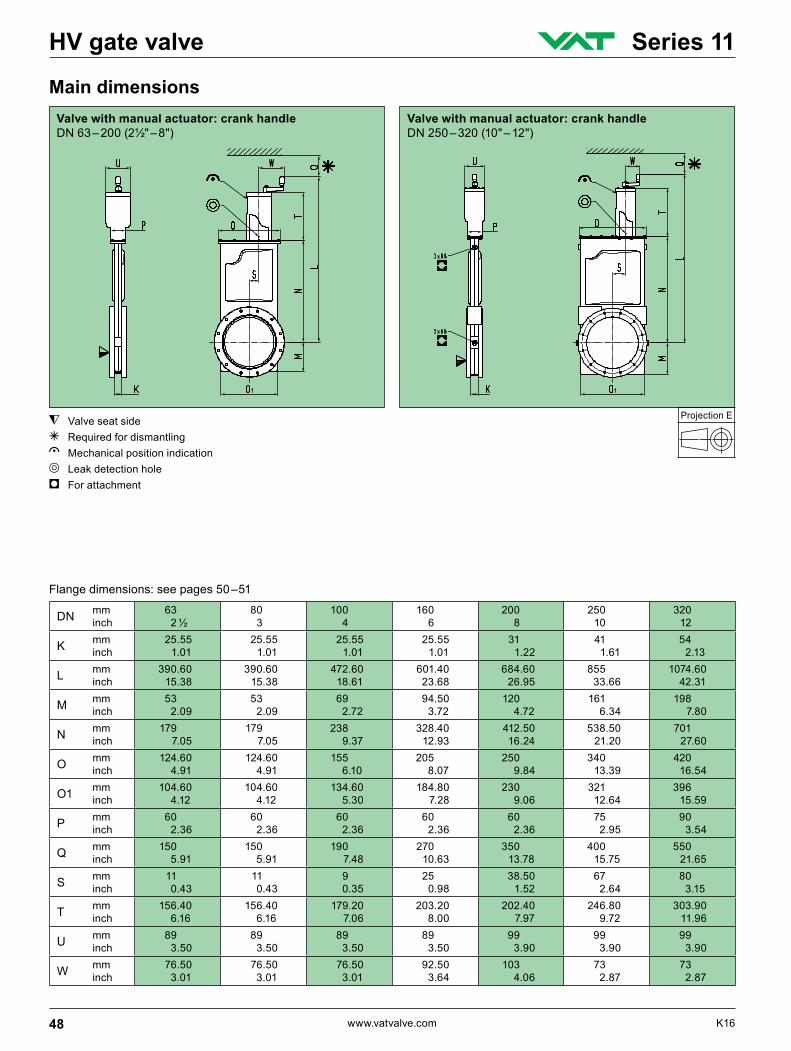
DN mm inch
63 2 ½
80 3
100 4
160 6
200 8
250 10
320 12
K mm inch
25.55 1.01
25.55 1.01
25.55 1.01
25.55 1.01
31 1.22
41 1.61
54 2.13
L mm inch
390.60 15.38
390.60 15.38
472.60 18.61
601.40 23.68
684.60 26.95
855 33.66
1074.60 42.31
M mm inch
53 2.09
53 2.09
69 2.72
94.50 3.72
120 4.72
161 6.34
198 7.80
N mm inch
179 7.05
179 7.05
238 9.37
328.40 12.93
412.50 16.24
538.50 21.20
701 27.60
O mm inch
124.60 4.91
124.60 4.91
155 6.10
205 8.07
250 9.84
340 13.39
420 16.54
O1 mm inch
104.60 4.12
104.60 4.12
134.60 5.30
184.80 7.28
230 9.06
321 12.64
396 15.59
P mm inch
60 2.36
60 2.36
60 2.36
60 2.36
60 2.36
75 2.95
90 3.54
Q mm inch
150 5.91
150 5.91
190 7.48
270 10.63
350 13.78
400 15.75
550 21.65
S mm inch
11 0.43
11 0.43
9 0.35
25 0.98
38.50 1.52
67 2.64
80 3.15
T mm inch
156.40 6.16
156.40 6.16
179.20 7.06
203.20 8.00
202.40 7.97
246.80 9.72
303.90 11.96
U mm inch
89 3.50
89 3.50
89 3.50
89 3.50
99 3.90
99 3.90
99 3.90
W mm inch
76.50 3.01
76.50 3.01
76.50 3.01
92.50 3.64
103 4.06
73 2.87
73 2.87
Main dimensionsValve with manual actuator: crank handle DN 250 – 320 (10" – 12")
Valve with manual actuator: crank handle DN 63 – 200 (2½" – 8")
Flange dimensions: see pages 50 –51
Valve seat side g Required for dismantlinge Mechanical position indicationd Leak detection holei For attachment
48 www.vatvalve.com K16
HV gate valve Series 11
Projection E
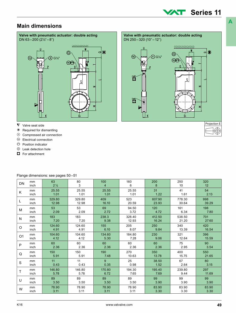
DN mm inch
63 2 ½
80 3
100 4
160 6
200 8
250 10
320 12
K mm inch
25.55 1.01
25.55 1.01
25.55 1.01
25.55 1.01
31 1.22
41 1.61
54 2.13
L mm inch
329.80 12.98
329.80 12.98
409 16.10
523 20.59
607.90 23.93
778.30 30.64
998 39.29
M mm inch
53 2.09
53 2.09
69 2.72
94.50 3.72
120 4.72
161 6.34
198 7.80
N mm inch
183 7.20
183 7.20
238.3 9.38
328.40 12.93
412.50 16.24
538.50 21.20
701 27.60
O mm inch
124.60 4.91
124.60 4.91
155 6.10
205 8.07
250 9.84
340 13.39
420 16.54
O1 mm inch
104.60 4.12
104.60 4.12
134.60 5.30
184.80 7.28
230 9.06
321 12.64
396 15.59
P mm inch
60 2.36
60 2.36
60 2.36
60 2.36
60 2.36
75 2.95
90 3.54
Q mm inch
150 5.91
150 5.91
190 7.48
270 10.63
350 13.78
400 15.75
550 21.65
S mm inch
11 0.43
11 0.43
9 0.35
25 0.98
38.50 1.52
67 2.64
80 3.15
T mm inch
146.80 5.78
146.80 5.78
170.80 6.72
194.30 7.65
195.40 7.69
239.80 9.44
297 11.69
U mm inch
89 3.50
89 3.50
89 3.50
89 3.50
99 3.90
99 3.90
99 3.90
W mm inch
78.90 3.11
78.90 3.11
78.90 3.11
78.90 3.11
83.90 3.30
83.90 3.30
83.90 3.30
Flange dimensions: see pages 50 –51
Valve seat side g Required for dismantlingb Compressed air connection c Electrical connectionf Position indicatord Leak detection holei For attachment
Main dimensionsValve with pneumatic actuator: double acting DN 250 – 320 (10“ – 12“)
Valve with pneumatic actuator: double acting DN 63 – 200 (2½“ – 8“)
49K16 www.vatvalve.com
Series 11A
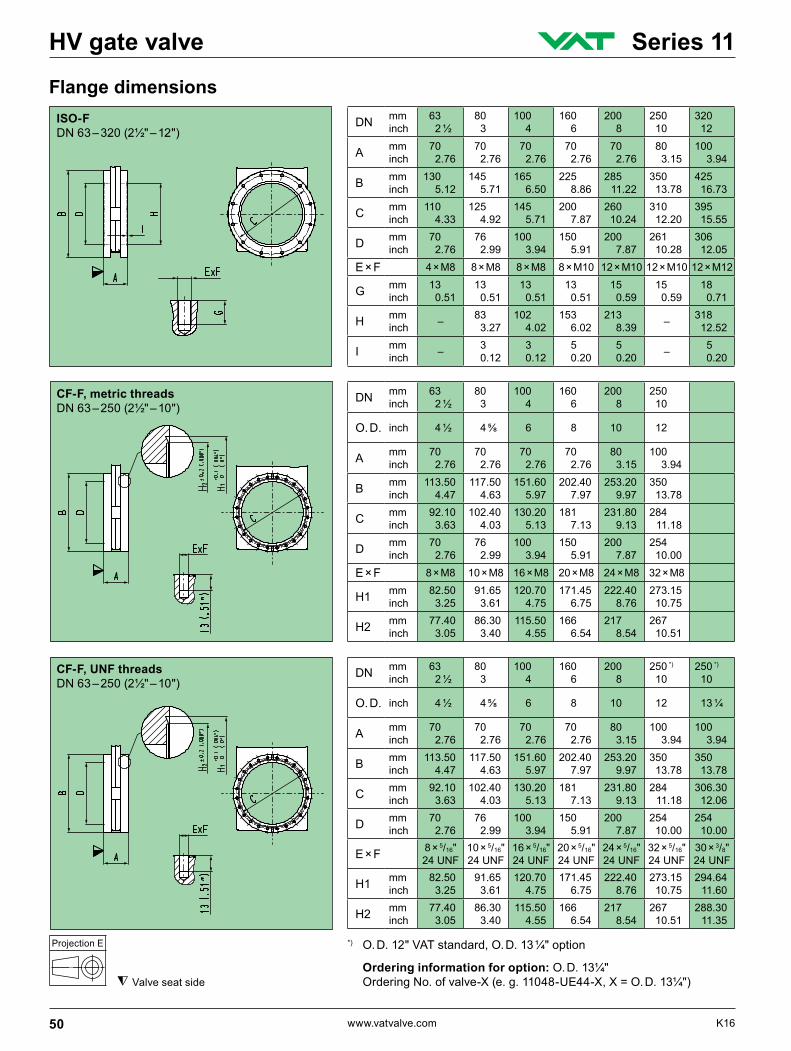
ISO-F DN 63 – 320 (2½" – 12")
Projection E
DN mm inch
63 2 ½
80 3
100 4
160 6
200 8
250 10
320 12
A mm inch
70 2.76
70 2.76
70 2.76
70 2.76
70 2.76
80 3.15
100 3.94
B mm inch
130 5.12
145 5.71
165 6.50
225 8.86
285 11.22
350 13.78
425 16.73
C mm inch
110 4.33
125 4.92
145 5.71
200 7.87
260 10.24
310 12.20
395 15.55
D mm inch
70 2.76
76 2.99
100 3.94
150 5.91
200 7.87
261 10.28
306 12.05
E × F 4 × M8 8 × M8 8 × M8 8 × M10 12 × M10 12 × M10 12 × M12
G mm inch
13 0.51
13 0.51
13 0.51
13 0.51
15 0.59
15 0.59
18 0.71
H mm inch – 83
3.27 102 4.02
153 6.02
213 8.39 – 318
12.52
I mm inch – 3
0.12 3 0.12
5 0.20
5 0.20 – 5
0.20
DN mm inch
63 2 ½
80 3
100 4
160 6
200 8
250 10
O. D. inch 4 ½ 4⅝ 6 8 10 12
A mm inch
70 2.76
70 2.76
70 2.76
70 2.76
80 3.15
100 3.94
B mm inch
113.50 4.47
117.50 4.63
151.60 5.97
202.40 7.97
253.20 9.97
350 13.78
C mm inch
92.10 3.63
102.40 4.03
130.20 5.13
181 7.13
231.80 9.13
284 11.18
D mm inch
70 2.76
76 2.99
100 3.94
150 5.91
200 7.87
254 10.00
E × F 8 × M8 10 × M8 16 × M8 20 × M8 24 × M8 32 × M8
H1 mm inch
82.50 3.25
91.65 3.61
120.70 4.75
171.45 6.75
222.40 8.76
273.15 10.75
H2 mm inch
77.40 3.05
86.30 3.40
115.50 4.55
166 6.54
217 8.54
267 10.51
DN mm inch
63 2 ½
80 3
100 4
160 6
200 8
250 *) 10
250 *) 10
O. D. inch 4 ½ 4⅝ 6 8 10 12 13 ¼
A mm inch
70 2.76
70 2.76
70 2.76
70 2.76
80 3.15
100 3.94
100 3.94
B mm inch
113.50 4.47
117.50 4.63
151.60 5.97
202.40 7.97
253.20 9.97
350 13.78
350 13.78
C mm inch
92.10 3.63
102.40 4.03
130.20 5.13
181 7.13
231.80 9.13
284 11.18
306.30 12.06
D mm inch
70 2.76
76 2.99
100 3.94
150 5.91
200 7.87
254 10.00
254 10.00
E × F 8 × 5/16" 24 UNF
10 × 5/16" 24 UNF
16 × 5/16" 24 UNF
20 × 5/16" 24 UNF
24 × 5/16" 24 UNF
32 × 5/16" 24 UNF
30 × 3/8" 24 UNF
H1 mm inch
82.50 3.25
91.65 3.61
120.70 4.75
171.45 6.75
222.40 8.76
273.15 10.75
294.64 11.60
H2 mm inch
77.40 3.05
86.30 3.40
115.50 4.55
166 6.54
217 8.54
267 10.51
288.30 11.35
Flange dimensions
Valve seat side
CF-F, metric threads DN 63 – 250 (2½" – 10")
CF-F, UNF threads DN 63 – 250 (2½" – 10")
*) O. D. 12" VAT standard, O. D. 13 ¼" option
Ordering information for option: O. D. 13¼" Ordering No. of valve-X (e. g. 11048-UE44-X, X = O. D. 13¼")
50 www.vatvalve.com K16
HV gate valve Series 11
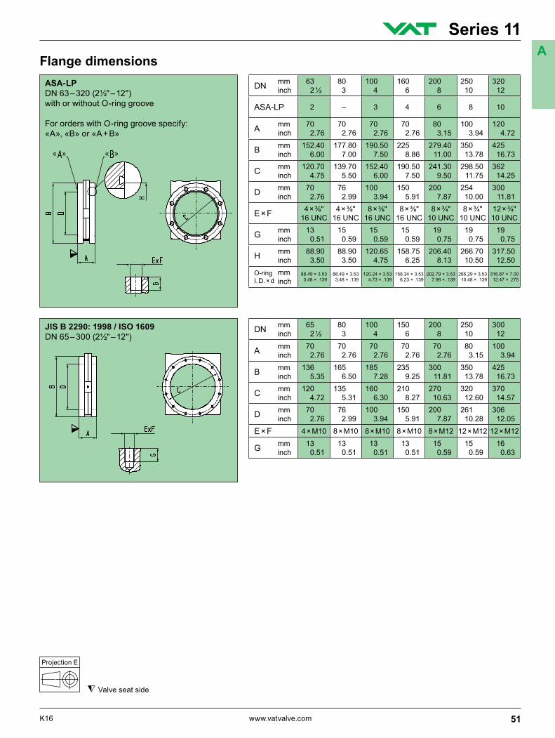
JIS B 2290: 1998 / ISO 1609 DN 65 – 300 (2½" – 12")
Projection E
DN mm inch
65 2 ½
80 3
100 4
150 6
200 8
250 10
300 12
A mm inch
70 2.76
70 2.76
70 2.76
70 2.76
70 2.76
80 3.15
100 3.94
B mm inch
136 5.35
165 6.50
185 7.28
235 9.25
300 11.81
350 13.78
425 16.73
C mm inch
120 4.72
135 5.31
160 6.30
210 8.27
270 10.63
320 12.60
370 14.57
D mm inch
70 2.76
76 2.99
100 3.94
150 5.91
200 7.87
261 10.28
306 12.05
E × F 4 × M10 8 × M10 8 × M10 8 × M10 8 × M12 12 × M12 12 × M12
G mm inch
13 0.51
13 0.51
13 0.51
13 0.51
15 0.59
15 0.59
16 0.63
Flange dimensions
Valve seat side
ASA-LP DN 63 – 320 (2½" – 12")with or without O-ring groove
For orders with O-ring groove specify:«A», «B» or «A + B»
DN mm inch
63 2 ½
80 3
100 4
160 6
200 8
250 10
320 12
ASA-LP 2 – 3 4 6 8 10
A mm inch
70 2.76
70 2.76
70 2.76
70 2.76
80 3.15
100 3.94
120 4.72
B mm inch
152.40 6.00
177.80 7.00
190.50 7.50
225 8.86
279.40 11.00
350 13.78
425 16.73
C mm inch
120.70 4.75
139.70 5.50
152.40 6.00
190.50 7.50
241.30 9.50
298.50 11.75
362 14.25
D mm inch
70 2.76
76 2.99
100 3.94
150 5.91
200 7.87
254 10.00
300 11.81
E × F 4 × ⅜" 16 UNC
4 × ⅜" 16 UNC
8 × ⅜" 16 UNC
8 × ⅜" 16 UNC
8 × ¾" 10 UNC
8 × ¾" 10 UNC
12 × ¾" 10 UNC
G mm inch
13 0.51
15 0.59
15 0.59
15 0.59
19 0.75
19 0.75
19 0.75
H mm inch
88.90 3.50
88.90 3.50
120.65 4.75
158.75 6.25
206.40 8.13
266.70 10.50
317.50 12.50
O-ring I. D. × d
mm inch
88.49 × 3.53 3.48 × .139
88.49 × 3.53 3.48 × .139
120.24 × 3.53 4.73 × .139
158.34 × 3.53 6.23 × .139
202.79 × 3.53 7.98 × .139
266.29 × 3.53 10.48 × .139
316.87 × 7.00 12.47 × .275
51K16 www.vatvalve.com
Series 11A