Embed Size (px)
Citation preview

HUR-160A
Reversible Plate
Operation manual
version number:20120911
- 1 -
CONTENTS
Contents…………………………………………………………………………1
Forward…………………………………………………………………………2
Feature …………………………………………………………………………2
Specification……………………………………………………………………2
Safety precautions ……………………………………………………………3
Safety checks …………………………………………………………………4
Maintenance……………………………………………………………………4
Maintenance checks……………………………………………………………5
Transport…………………………………………………………………………5
Application………………………………………………………………………5
Description………………………………………………………………………7
Transport precautions…………………………………………………………8
Recommendations on compaction……………………………………………9
Engine check before starting…………………………………………………10
Starting the engine……………………………………………………………11
Operation the engine…………………………………………………………13
Forward and reverse motion…………………………………………………13
Stopping the engine……………………………………………………………13
Maintenance……………………………………………………………………15
Engine oil………………………………………………………………………16
Hydraulic pressure control……………………………………………………17
Exciter …………………………………………………………………………17
V-Belt……………………………………………………………………………18
Sediment cup cleaning………………………………………………………18
Spark plugs……………………………………………………………………18
Carburetor adjustment………………………………………………………19
Air filler service………………………………………………………………20
Troubleshooting………………………………………………………………20
Diagram………………………………………………………………………22
- 2 -
FOREWARD
◇For your own safety and protection from bodily injuries, carefully read, understand
and follow the safety instructions in this manual.
◇Please operate and maintain your machine in accordance with the instructions in
this manual.
◇Defective machine parts are to be replaced as soon as possible.
◇Keep this owner's manual handy, so you can refer to it at any time.
◇No part of this publication may be reproduced without written permission.
◇We expressly reserve the right to technical modifications- even without express
due notice - which aim at improving our machines or their safety standards.
FEATURE
Compaction in confined areas of granular and mixed soils. Ideal for compaction
in utility trenches, along highways, dams, packing areas, airport, bridge construction,
railroad beds, along foundations, walls and abutments.
Specially designed shock mount system offers a virtually vibration-free guide
handle for increased operator comfort and reduced operator fatigue. Infinitely
variable forward and reverse operation, including "spot" Compaction. Oil pressure
and battery charge level indications. Tough ductile iron base plate is extremely
durable even under extreme conditions and provides for long service life. Compact
design with low center of gravity and low working height. An adjustable guide handle
can be locked into a vertical position for easy transport and storage.
SPECIFICATION
Max. Forwards or backwards speed (earth and environment): 21m/min
Max. Plate size: 630m2/h
Max. Climbing angle: 30°
Power transmission: From drive engine directly to exciter unit via centrifugal clutch
and V-belt
Weight: 166KG
Wide: 500mm
- 3 -
Compacting force: 30KN
Vibration frequency: 90HZ
Engine type: HONDA GX270
Engine oil type: Recommended SAE10W-30
Engine oil capacity: 1.1L
Fuel type: Unleaded gasoline with a pump octane rating of 90 or higher
Tank capacity: 6.0L
Fuel oil: 1.1L/h
Max. Power output: 9HP
Working height of handle: 800-1143mm
SAFETY PRECAUTIONS
1. Read and understand this owner's manual before operating the machine.
2. It is possible that this vibrator plate exceeds the admissible sound lever of 89 dB
(A) According to the rules for the prevention of accidents regarding emission of noise,
the employees have to wear protection if the sound level reaches 89 dB (A) or more.
3. Pull the starter grip lightly until you feel resistance, then pull briskly. Return the
starter grip gently.
4. Be careful the handle can't keep away of the handle when operate the machine.
5. The operator has to stop the engine of the vibratory plate before going on breaks.
The machine has to be placed such that it cannot turn over.
6. Refuel the engine must always be stopped, using all necessary safety precautions.
When refilling fuel tank, do not allow fuel to come into contact with the hot parts of
the engine or spill onto the ground.
7. Do not smoke or handle open fire near this machine.
8. The tank lid must fit tightly. Shut off fuel lever, if available when stopping the
engine. For long distance transports of machine operated by fuel or fuel-mixtures,
the fuel tank has to be drained completely.
9. Do not operate the machine in areas where explosions may occur.
10. Make sure that sufficient fresh air is available when operating vibratory plates
with combustion engines in enclosed areas, tunnels, aditus, moat and deep

- 4 -
trenches.
11. You be careful when working around pipes or ducts protruding from the floor or
slab edges.
12. When working near the edges of breaks, pits, slopes, trenches and platforms,
vibratory plates are to be operated such that there is no danger of their turning over
or dropping in.
13. Make sure soil or subsoil to be compacted has a high enough load carrying
capacity.
14. When traveling backwards the operator has to guide the vibration plate laterally
by its guide handle so that he will not be squeezed between the handle and a
possible obstacle. Special care is required when working on uneven ground or when
you compacting coarse material. Make sure of a firm stand when operating the
machine under such conditions.
15. Machines with integrated transport trolley may not be parked or stored on the
trolley. This device has only been designed to transport the machine.
SAFETY CHECKS
1. Vibratory plates may only be operated with all safety devices installed.
2. Before starting operation, the operator has to that all shields and covers are in
place, and all nuts, bolts, and screws are tightened.
3. In case of defects jeopardizing the operational safety of the vibration plate, the
machine has to be stopped immediately.
4. Process materials and operating fuels must be stowed away in receptacles or
containers marked according to the respective manufacturers specifications.
5. Use proper lubricating oil and fuel as recommended.
MAINTENANCE
1. Only use original spare parts. Modifications to this machine, including the
adjustment of the maximum engine speed set by the manufacturer, are subject to
the express approval of our company. In case of nonobservance all liabilities shall be
refused.
- 5 -
2. Only use original spare parts. Modifications to this machine, including the
adjustment of the maximum engine speed set by the manufacturer, are subject to
the express approval of our company. In case of nonobservance all liabilities shall be
refused.
3. As soon as maintenance and repair jobs have been completed all safety devices
have to be reinstalled properly.
4. Do not hose down the machine with water after each use to avoid possible
malfunctions. Do not use high pressure washers or chemical products.
MAINTENANCE CHECKS
According to the conditions and frequency of use, vibratory plates have to be
checked for safe operation at least once a year by skilled technicians, such as those
found at our service depots and have to be repaired if necessary.
TRANSPORT
1. During transport, loading and unloading of vibration plates by means of lifting
devices, appropriate slinging means or hooks have to be used on the lifting points
provided for this purpose on the vibratory plate.
2. The load-carrying capacity of the loading ramps has to be sufficient and the ramps
have to be secure such that they cannot turn over. Make sure that no one be
endangered by machines turning over by slopping or by moving machine parts.
3. When being transported on vehicles, precautions have to be taken that vibration
plates do not slip or turn over.
APPLICATIONS
The machines is perfectly suited for the compaction of all types of soil including
semi-cohesive soils in trench and surface compaction applications as well as for the
compaction of asphalt pavements and the vibration of interlocking paving stones.
This machine is the most universally deployable machine of this line of products
thanks to the optimum balance between the centrifugal force and the contact
surface.
- 6 -
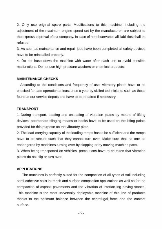
DIMENSIONS
Max. Allowable in continuous operation:
DESCRIPTION
The vibration required for compaction is produced by the exciter (4) which is
firmly joined to the lower mass (3). This exciter (4) is designed as a central vibrator
with aligned vibrations. Such a principle permits the direction of vibration to be
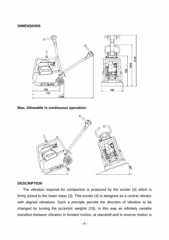
changed by turning the eccentric weights (16). In this way an infinitely variable
transition between vibration in forward motion, at standstill and in reverse motion is
- 7 -
possible. This process is hydraulically controlled with the operating control handle (8)
on the centre pole head (9).
The drive engine (1) is anchored to the upper mass (2) and drives the exciter (4).
The torque is transmitted by means of a friction connection through the centrifugal
clutch (14) and the exciter V-belt (13).
The centrifugal clutch (14) interrupts the power transmission to the exciter (4) at
low engine turning speed, thus allowing for a perfect idling speed of the drive engine
(1). The turning speed of the engine (1) can be infinitely adjusted by way of the
throttle lever (6).
The upper (2) and lower (3) masses are connected to each other by 4
vibration-damping shock mounts (11). This damping system prevents the very high
frequencies from being transmitted to the upper mass (2). As a result the function
ability of the drive engine (1) is retained in spite of the high compaction performance.
The drive engine (1) works according to the 4-stroke principle, is started by way
of a recoil starter, sucks in combustion air over a dry air filter (7) and is air-cooled.
To facilitate the starting procedure the drive engine (1) has a decompression
mechanism.
- 8 -
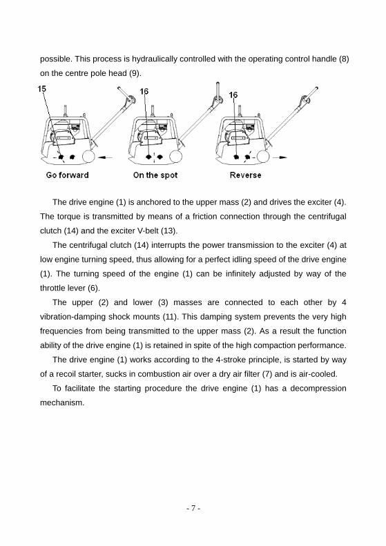
TRANSPORT PRECAUTIONS
1. To transport the vibration plates, use only suitable lifting equipment with a
minimum load-bearing capacity of 200 kg.
2. Only attach suitable tackle at the central lifting point (5) provided.
3. Always tie down the vibratory plate by the protective frame (10) and latch the
center pole in place during transport of the vibratory plate on the loading area of a
transport vehicle.
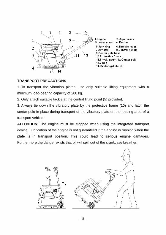
ATTENTION! The engine must be stopped when using the integrated transport
device. Lubrication of the engine is not guaranteed if the engine is running when the
plate is in transport position. This could lead to serious engine damages.
Furthermore the danger exists that oil will spill out of the crankcase breather.
- 9 -
RECOMMENDATIONS ON COMPACTION
Ground conditions
The Max. Compaction depth depends on several factors relating to the ground
condition, such as moisture, grain distribution etc. It is therefore not possible to
specify exact values.
Recommendation: In each case determine the max. Compaction depth with
compaction tests and soil samples
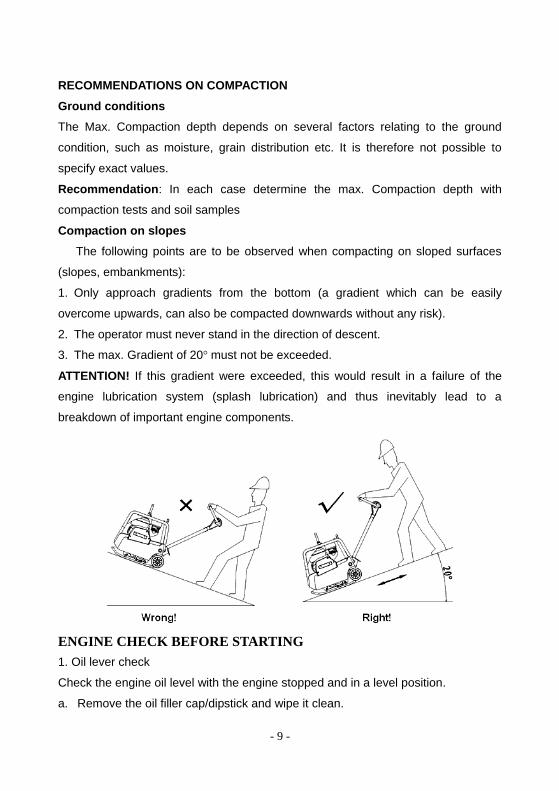
Compaction on slopes
The following points are to be observed when compacting on sloped surfaces
(slopes, embankments):
1. Only approach gradients from the bottom (a gradient which can be easily
overcome upwards, can also be compacted downwards without any risk).
2. The operator must never stand in the direction of descent.
3. The max. Gradient of 20° must not be exceeded.
ATTENTION! If this gradient were exceeded, this would result in a failure of the
engine lubrication system (splash lubrication) and thus inevitably lead to a
breakdown of important engine components.
ENGINE CHECK BEFORE STARTING
1. Oil lever check
Check the engine oil level with the engine stopped and in a level position.
a. Remove the oil filler cap/dipstick and wipe it clean.
- 10 -
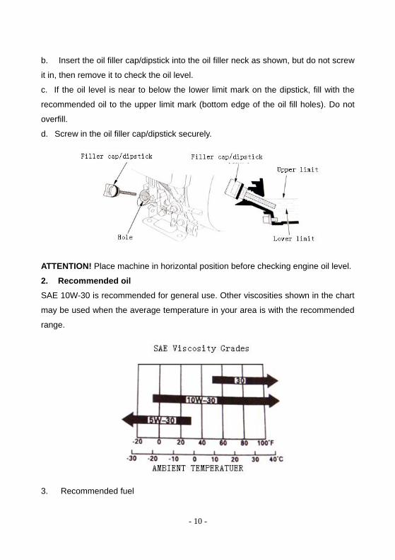
b. Insert the oil filler cap/dipstick into the oil filler neck as shown, but do not screw
it in, then remove it to check the oil level.
c. If the oil level is near to below the lower limit mark on the dipstick, fill with the
recommended oil to the upper limit mark (bottom edge of the oil fill holes). Do not
overfill.
d. Screw in the oil filler cap/dipstick securely.
ATTENTION! Place machine in horizontal position before checking engine oil level.
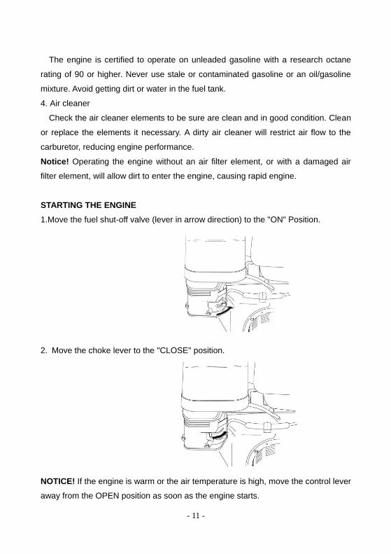
2. Recommended oil
SAE 10W-30 is recommended for general use. Other viscosities shown in the chart
may be used when the average temperature in your area is with the recommended
range.
3. Recommended fuel
- 11 -
The engine is certified to operate on unleaded gasoline with a research octane
rating of 90 or higher. Never use stale or contaminated gasoline or an oil/gasoline
mixture. Avoid getting dirt or water in the fuel tank.
4. Air cleaner
Check the air cleaner elements to be sure are clean and in good condition. Clean
or replace the elements it necessary. A dirty air cleaner will restrict air flow to the
carburetor, reducing engine performance.
Notice! Operating the engine without an air filter element, or with a damaged air
filter element, will allow dirt to enter the engine, causing rapid engine.
STARTING THE ENGINE
1.Move the fuel shut-off valve (lever in arrow direction) to the "ON" Position.
2. Move the choke lever to the "CLOSE" position.
NOTICE! If the engine is warm or the air temperature is high, move the control lever
away from the OPEN position as soon as the engine starts.
- 12 -
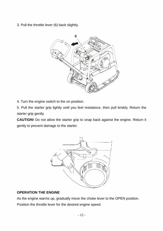
3. Pull the throttle lever (6) back slightly.
4. Turn the engine switch to the on position.
5. Pull the starter grip lightly until you feel resistance, then pull briskly. Return the
starter grip gently.
CAUTION! Do not allow the starter grip to snap back against the engine. Return it
gently to prevent damage to the starter.
OPERATION THE ENGINE
As the engine warms up, gradually move the choke lever to the OPEN position.
Position the throttle lever for the desired engine speed.
- 13 -
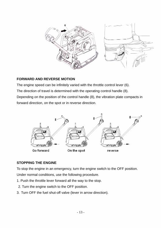
FORWARD AND REVERSE MOTION
The engine speed can be infinitely varied with the throttle control lever (6).
The direction of travel is determined with the operating control handle (8).
Depending on the position of the control handle (8), the vibration plate compacts in
forward direction, on the spot or in reverse direction.
STOPPING THE ENGINE
To stop the engine in an emergency, turn the engine switch to the OFF position.
Under normal conditions, use the following procedure.
1. Push the throttle lever forward all the way to the stop.
2. Turn the engine switch to the OFF position.
3. Turn OFF the fuel shut-off valve (lever in arrow direction).
- 14 -
MAINTENANCE
MAINTENANCE SCHEDULE
Check all external screw connections for tight fit approx. 8 hours after first
operation.
Parts Maintenance Jobs Maintenance
Interval
Air filter
Fuel tank
Engine oil
Exciter
Bowden
cable
Check for external damage and tight fit.
Check filter cartridge, clean or replace if
necessary. Check tank lid for tight fit,
replace if necessary.
Check oil level, top up if necessary.
Check for tightness.
Check to see smooth running.
daily
Engine oil First oil change. after 20 hours
- 15 -
Ignition
system
Exciter
Hydraulic
control
V-belt
Protective
frame
Clean spark plug, check spark plug gap
0,7 mm.
Check attachment screws for tight fit.
Check oil level, top up if necessary.
Check V-belt tension-retension, if need
be.
Check fastening screws of protective
frame and
central suspension for tight fit.
monthly
Engine oil
Exhaust
muffler
Further oil changes.
Remove combustion residue from spark
arrester.
after 100 hours
Exciter Check oil level-fill up, if need be. after 150 hours
Exciter Oil change. after 250 hours
Valve
clearance
Check, set - 0,15mm intake valve,
0,20mm exhaust valve. after 300 hours
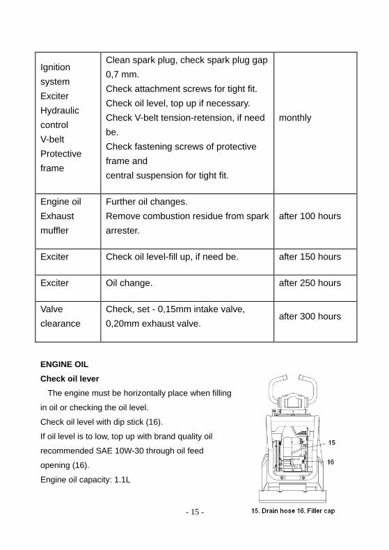
ENGINE OIL
Check oil lever
The engine must be horizontally place when filling
in oil or checking the oil level.
Check oil level with dip stick (16).
If oil level is to low, top up with brand quality oil
recommended SAE 10W-30 through oil feed
opening (16).
Engine oil capacity: 1.1L
- 16 -
Oil change
Drain the used oil when the engine is warm. Warm oil drains quickly and completely.
1. Please a suitable container below the engine to catch the used oil, and then
remove the oil filler cap/dipstick, oil drain plug and washer.
2. Release the waist oil drain hose (15) and collect the draining oil in an appropriate
container.
3. Attach the waist oil drain hose (15) back again.
4. Pour the recommended oil through the oil filler tube (16) and then check the oil
level.
ATTENTION! Place machine in horizontal position before checking engine oil level.
5. Install the oil filter cap.
NOTICE! Please dispose of used motor oil in a manner that is compatible with the
environment. We suggest you take used oil in a sealed container to your local
recycling center or service station for reclamation. Do not throw it in the trash; pour it
on the ground, or down a drain.
HYDRAULIC PRESSURE CONTROL
Check oil lever
1. Move center pole into vertical position.
2. Push operating control handle (8) to forward travel position.
3. Remove the filler cap.
4. The oil level must reach the upper edge of the gear, add Fuchs Renolin MR 520
hydraulic fluid if required.
5. Screw in the oil filler cap.
NOTICE! The oil capacity: 0.4L. Hydraulic control system is self-bleeding.
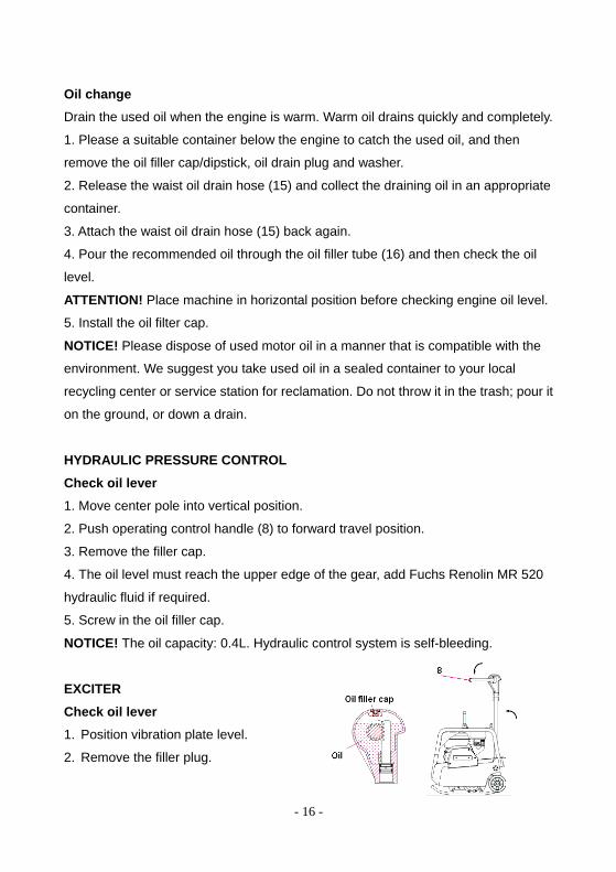
EXCITER
Check oil lever
1. Position vibration plate level.
2. Remove the filler plug.
- 17 -
3. The exciter oil capacity must keep 0.6L. 4. Recommended oil: SAE 10W-30
5. Screw in the filler cap.
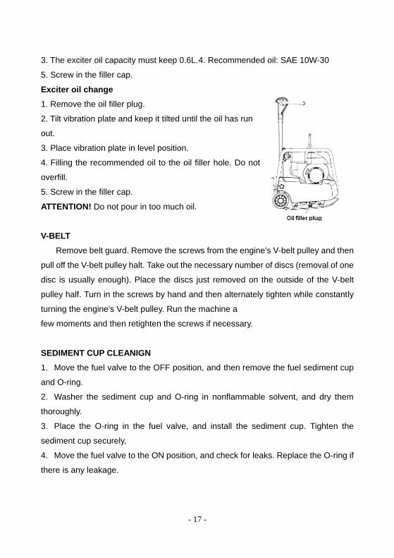
Exciter oil change
1. Remove the oil filler plug.
2. Tilt vibration plate and keep it tilted until the oil has run
out.
3. Place vibration plate in level position.
4. Filling the recommended oil to the oil filler hole. Do not
overfill.
5. Screw in the filler cap.
ATTENTION! Do not pour in too much oil.
V-BELT
Remove belt guard. Remove the screws from the engine's V-belt pulley and then
pull off the V-belt pulley halt. Take out the necessary number of discs (removal of one
disc is usually enough). Place the discs just removed on the outside of the V-belt
pulley half. Turn in the screws by hand and then alternately tighten while constantly
turning the engine's V-belt pulley. Run the machine a
few moments and then retighten the screws if necessary.
SEDIMENT CUP CLEANIGN
1. Move the fuel valve to the OFF position, and then remove the fuel sediment cup
and O-ring.
2. Washer the sediment cup and O-ring in nonflammable solvent, and dry them
thoroughly.
3. Place the O-ring in the fuel valve, and install the sediment cup. Tighten the
sediment cup securely,
4. Move the fuel valve to the ON position, and check for leaks. Replace the O-ring if
there is any leakage.
- 18 -
SPARK PLUGS
Recommended spark plugs: BPR6ES (NGK), W20EPR-U (INPPONDENSO). For
good performance, the spark plug must be properly gapped and free of deposits.
1. Disconnect the spark plug cap, and remove any dirt from around the spark plug
area.
Warning: If the engine has been running, the muffler will be very hot. Be careful not
to touch the muffler.
2. Remove the spark plug with a 13/16-inch spark plug wrench.
3. Inspect the spark plug. Replace it if the electrodes are worn heavy carbon
buildup is found, or if the insulator is cracked or chipped.
4. Measure the spark plug electrode gap with a suitable gauge. The gap should be
0.028-0.031 in (0.70 - 0.80 mm). Correct the gap, if necessary, by carefully bending
the side electrode.
5. Check that the spark plug washer is in good condition. Install the spark plug
carefully, by hand, to avoid cross-threading.
6. After the spark plug seats, tighten with a 13/16-inch spark plug wrench to
compress the sealing washer.
7. When installing a new spark plug, tighten 1/2 turn after the spark plug seats to
compress the washer.
8. When reinstalling the original spark plug, tighten 1/8 -1/4 turn after the spark plug
seats to compress the washer.
9. Attach the spark plug cap.
NOTICE! The recommended spark plug has the correct heat range for normal engine
operating temperatures. A loose spark plug can overheat and damage the engine.
Over tightening the spark plug can damage the threads in the cylinder head.
CARBURETTOR ADJUSTMENT
1. Start the engine outdoors, and allow it to warm up to operating temperature.
2. With the engine idling, turn the highest idle rpm screw in or out to the setting that
produces the highest idle rpm.
3. Turn the throttle stop screw to obtain the standard idle speed.
- 19 -
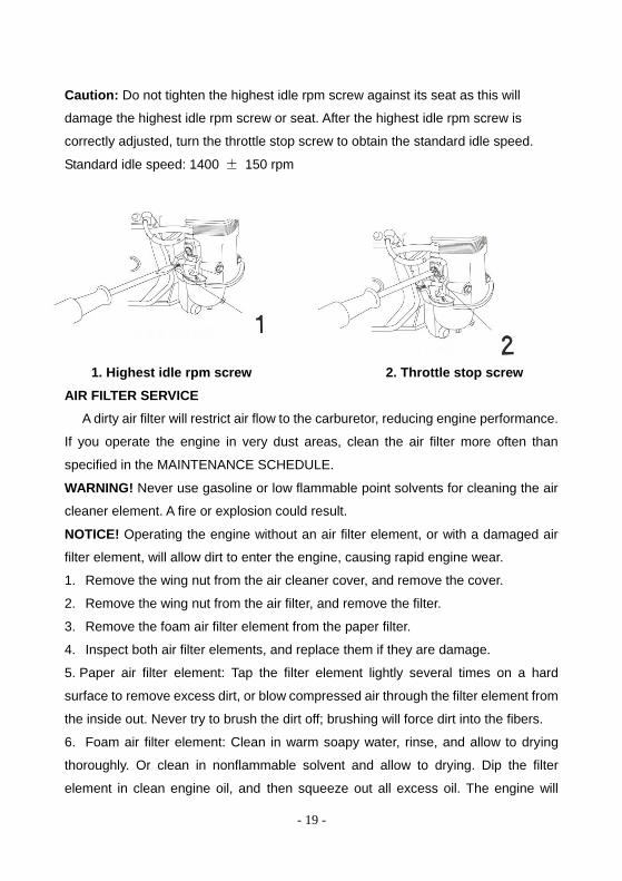
Caution: Do not tighten the highest idle rpm screw against its seat as this will
damage the highest idle rpm screw or seat. After the highest idle rpm screw is
correctly adjusted, turn the throttle stop screw to obtain the standard idle speed.
Standard idle speed: 1400 ± 150 rpm
1. Highest idle rpm screw 2. Throttle stop screw
AIR FILTER SERVICE
A dirty air filter will restrict air flow to the carburetor, reducing engine performance.
If you operate the engine in very dust areas, clean the air filter more often than
specified in the MAINTENANCE SCHEDULE.
WARNING! Never use gasoline or low flammable point solvents for cleaning the air
cleaner element. A fire or explosion could result.
NOTICE! Operating the engine without an air filter element, or with a damaged air
filter element, will allow dirt to enter the engine, causing rapid engine wear.
1. Remove the wing nut from the air cleaner cover, and remove the cover.
2. Remove the wing nut from the air filter, and remove the filter.
3. Remove the foam air filter element from the paper filter.
4. Inspect both air filter elements, and replace them if they are damage.
5. Paper air filter element: Tap the filter element lightly several times on a hard
surface to remove excess dirt, or blow compressed air through the filter element from
the inside out. Never try to brush the dirt off; brushing will force dirt into the fibers.
6. Foam air filter element: Clean in warm soapy water, rinse, and allow to drying
thoroughly. Or clean in nonflammable solvent and allow to drying. Dip the filter
element in clean engine oil, and then squeeze out all excess oil. The engine will
- 20 -
smoke when started if too much oil is left in the foam.
TROUBLESHOOTING
Reverse speed too low
Cause: -Tool little hydraulic oil in the centre pole head.
-Air in hydraulic control.
Remedy: -Top up hydraulic oil.
-Bleed system.
Forward speed too low
Cause: -Too much oil in the centre pole head.
Remedy: -Correct oil level accordance mark.
No advance
Cause: -Mechanical fault.
Remedy: -Contact our service dept.
Loss of hydraulic oil
Cause: -Leaks, hydraulic hose detective.
Remedy: -Change detective parts.
NOTICE! Bleed system after every dismantling operation.
Engine does not start
Cause: -Fuel tank empty.
-Fuel shut-off valve dose.
-Air filter dirty.
-Stop button detective.
-Recoil starter detective.
-Oil alert system has stopped engine.
Remedy: -Fuel up.
-Open.
-Clean.
-Repair.
-Repair.
-Fill up with engine oil.
- 21 -
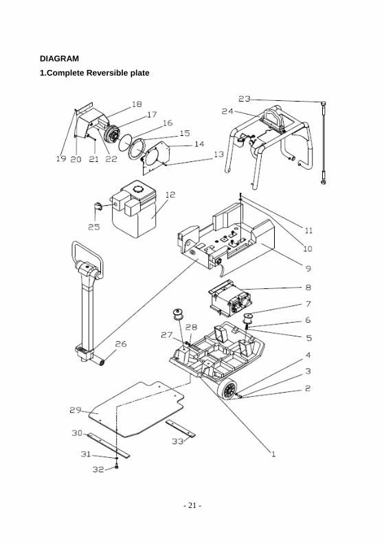
DIAGRAM
1.Complete Reversible plate
- 22 -
Item Part Drawing number Description Qty
1 100 HUR160A-10 Base plate 1
2 101 HUR160A-09 Tire 2
3 102 GB/T70.1-2000 Screw M12×30 2
4 103 Gasket 12 2
5 104 GB/T6170-2000 Nut M12 4
6 105 Gasket 12 8
7 106 HUR160A-11 Damp block 4
8 107 HUR160A-07 Exciter cpl. 1
9 108 HUR160A-06 Upper Mass 1
10 109 GB/T95-1985 Washer 10 4
11 110 GB/T5783-2000 Bolt M10×50 4
12 111 Engine GX270 1
13 112 GB/T70.1-2000 Screw 3/8″×25 3
14 113 HUR160A-03 Duct 1
15 114 HUR160A-02 Spacer 2
16 115 Belt XPA 907 1
17 116 HUR160A-04 Centrifugal Clutch 1
18 117 HUR160A-05 Belt guard 1
19 118 GB/T70.1-2000 Screw M4×16 2
20 119 Plastic plate 1
21 120 GB/T70.1-2000 Screw M4×70 3
22 121 GB/T6183-2000 Nut M4 2
23 122 House pipe 1
24 123 HUR160A-01 Hood assembly 1
25 124 HUR160A 附图Ⅰ Hood 1
26 125 HUR160A-08 Armrest assembly 1
27 126 Plug M12×1.25×16 1
28 127 Copper backing 1
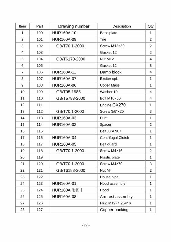
- 23 -
30 129 HUR160A-20-01 Dampening pad board I 1
31 130 HUR160A-20-02 Washer 10 (Options) 4
32 131 Bolt M10X25 (Options) 4
33 132 Dampening pad board II 1
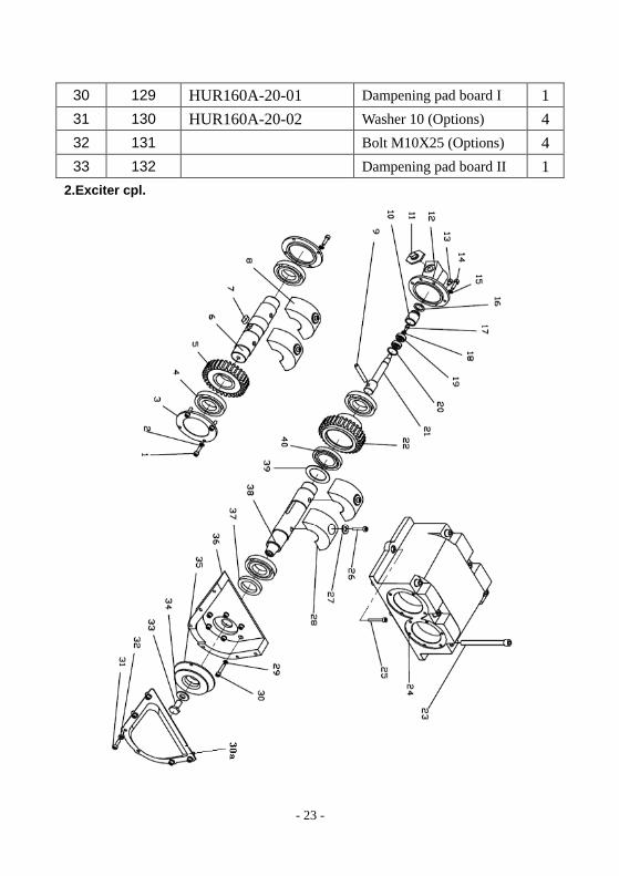
2.Exciter cpl.
- 24 -
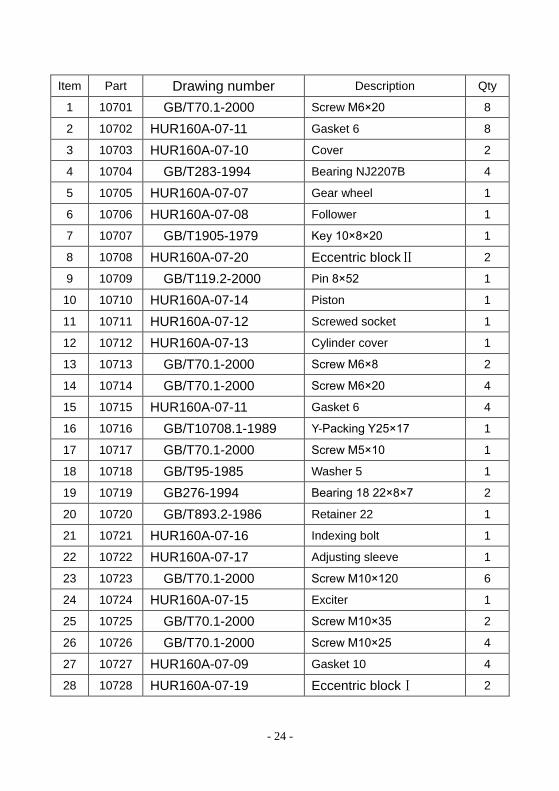
Item Part Drawing number Description Qty
1 10701 GB/T70.1-2000 Screw M6×20 8
2 10702 HUR160A-07-11 Gasket 6 8
3 10703 HUR160A-07-10 Cover 2
4 10704 GB/T283-1994 Bearing NJ2207B 4
5 10705 HUR160A-07-07 Gear wheel 1
6 10706 HUR160A-07-08 Follower 1
7 10707 GB/T1905-1979 Key 10×8×20 1
8 10708 HUR160A-07-20 Eccentric blockⅡ 2
9 10709 GB/T119.2-2000 Pin 8×52 1
10 10710 HUR160A-07-14 Piston 1
11 10711 HUR160A-07-12 Screwed socket 1
12 10712 HUR160A-07-13 Cylinder cover 1
13 10713 GB/T70.1-2000 Screw M6×8 2
14 10714 GB/T70.1-2000 Screw M6×20 4
15 10715 HUR160A-07-11 Gasket 6 4
16 10716 GB/T10708.1-1989 Y-Packing Y25×17 1
17 10717 GB/T70.1-2000 Screw M5×10 1
18 10718 GB/T95-1985 Washer 5 1
19 10719 GB276-1994 Bearing 18 22×8×7 2
20 10720 GB/T893.2-1986 Retainer 22 1
21 10721 HUR160A-07-16 Indexing bolt 1
22 10722 HUR160A-07-17 Adjusting sleeve 1
23 10723 GB/T70.1-2000 Screw M10×120 6
24 10724 HUR160A-07-15 Exciter 1
25 10725 GB/T70.1-2000 Screw M10×35 2
26 10726 GB/T70.1-2000 Screw M10×25 4
27 10727 HUR160A-07-09 Gasket 10 4
28 10728 HUR160A-07-19 Eccentric blockⅠ 2

- 25 -
29 10729 HUR160A-07-11 Gasket 6 6
30 10730 GB/T70.1-2000 Screw M6×30 6
30a 10730a HUR160A-07-01 Cover the 1
31 10731 GB/T5783-2000 Bolt M6×20 6
32 10732 HUR160A-07-05 Washer 6 6
33 10733 HUR160A-07-04 Bolt 1
34 10734 HUR160A-07-03 Gasket 12 1
35 10735 HUR160A-07-06 Pinion 1
36 10736 HUR160A-07-02 Belt Shroud 1
37 10737 GB/T13871-1992 Packing FB55×35×8 1
38 10738 HUR160A-07-18 Driver 1
39 10739 GB/T894.2-1986 Retainer 40 1
40 10740 GB/T276-1994 Bearing 16008 68×40×9 1
- 26 -
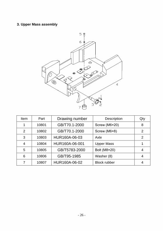
3. Upper Mass assembly
Item Part Drawing number Description Qty
1 10801 GB/T70.1-2000 Screw (M6×20) 8
2 10802 GB/T70.1-2000 Screw (M6×8) 2
3 10803 HUR160A-06-03 Axle 2
4 10804 HUR160A-06-001 Upper Mass 1
5 10805 GB/T5783-2000 Bolt (M8×20) 4
6 10806 GB/T95-1985 Washer (8) 4
7 10807 HUR160A-06-02 Block rubber 4
- 27 -
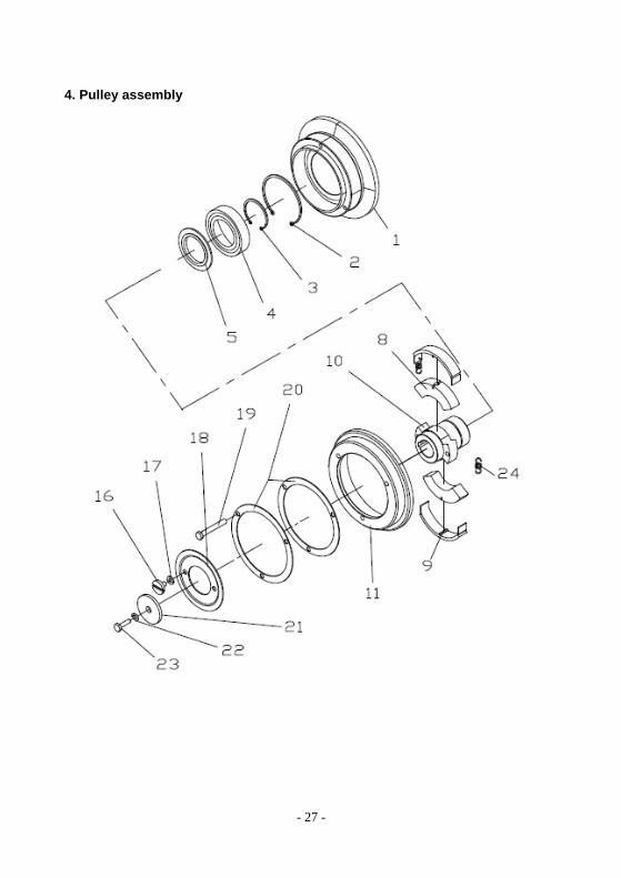
4. Pulley assembly
- 28 -
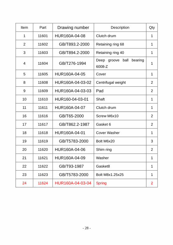
Item Part Drawing number Description Qty
1 11601 HUR160A-04-08 Clutch drum 1
2 11602 GB/T893.2-2000 Retaining ring 68 1
3 11603 GB/T894.2-2000 Retaining ring 40 1
4 11604 GB/T276-1994 Deep groove ball bearing
6008-Z 1
5 11605 HUR160A-04-05 Cover 1
8 11608 HUR160A-04-03-02 Centrifugal weight 2
9 11609 HUR160A-04-03-03 Pad 2
10 11610 HUR160-04-03-01 Shaft 1
11 11611 HUR160A-04-07 Clutch drum 1
16 11616 GB/T65-2000 Screw M6x10 2
17 11617 GB/T862.2-1987 Gasket 6 2
18 11618 HUR160A-04-01 Cover Washer 1
19 11619 GB/T5783-2000 Bolt M6x20 3
20 11620 HUR160A-04-06 Shim ring 2
21 11621 HUR160A-04-09 Washer 1
22 11622 GB/T93-1987 Gasket8 1
23 11623 GB/T5783-2000 Bolt M8x1.25x25 1
24 11624 HUR160A-04-03-04 Spring 2
- 29 -
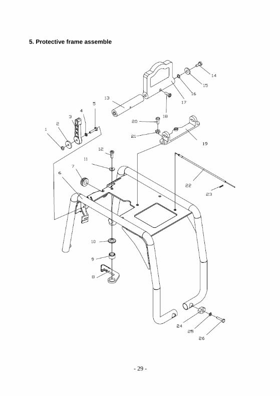
5. Protective frame assemble
- 30 -
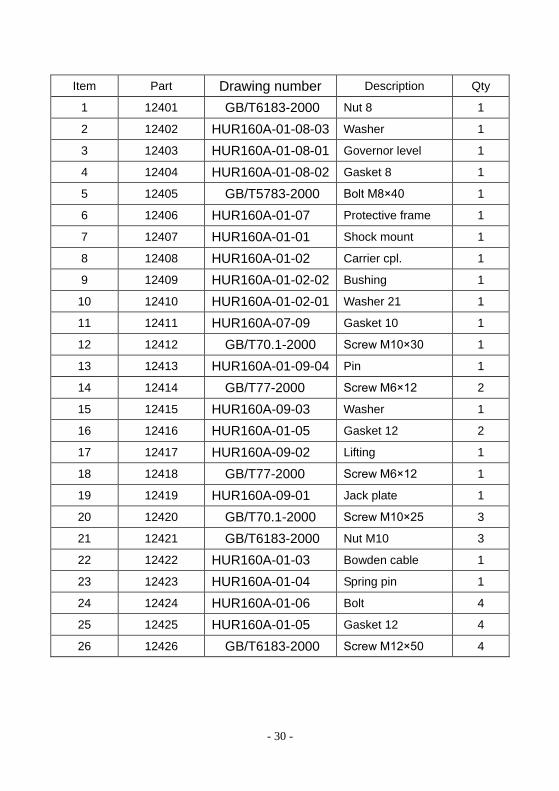
Item Part Drawing number Description Qty
1 12401 GB/T6183-2000 Nut 8 1
2 12402 HUR160A-01-08-03 Washer 1
3 12403 HUR160A-01-08-01 Governor level 1
4 12404 HUR160A-01-08-02 Gasket 8 1
5 12405 GB/T5783-2000 Bolt M8×40 1
6 12406 HUR160A-01-07 Protective frame 1
7 12407 HUR160A-01-01 Shock mount 1
8 12408 HUR160A-01-02 Carrier cpl. 1
9 12409 HUR160A-01-02-02 Bushing 1
10 12410 HUR160A-01-02-01 Washer 21 1
11 12411 HUR160A-07-09 Gasket 10 1
12 12412 GB/T70.1-2000 Screw M10×30 1
13 12413 HUR160A-01-09-04 Pin 1
14 12414 GB/T77-2000 Screw M6×12 2
15 12415 HUR160A-09-03 Washer 1
16 12416 HUR160A-01-05 Gasket 12 2
17 12417 HUR160A-09-02 Lifting 1
18 12418 GB/T77-2000 Screw M6×12 1
19 12419 HUR160A-09-01 Jack plate 1
20 12420 GB/T70.1-2000 Screw M10×25 3
21 12421 GB/T6183-2000 Nut M10 3
22 12422 HUR160A-01-03 Bowden cable 1
23 12423 HUR160A-01-04 Spring pin 1
24 12424 HUR160A-01-06 Bolt 4
25 12425 HUR160A-01-05 Gasket 12 4
26 12426 GB/T6183-2000 Screw M12×50 4
- 31 -
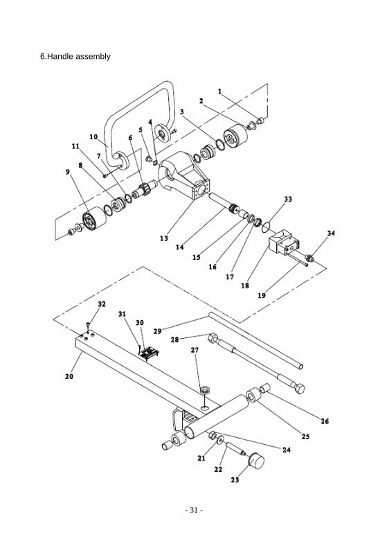
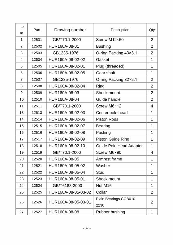
6.Handle assembly
- 32 -
Ite
m Part Drawing number Description Qty
1 12501 GB/T70.1-2000 Screw M12×50 2
2 12502 HUR160A-08-01 Bushing 2
3 12503 GB1235-1976 O-ring Packing 43×3.1 2
4 12504 HUR160A-08-02-02 Gasket 1
5 12505 HUR160A-08-02-01 Plug (threaded) 1
6 12506 HUR160A-08-02-05 Gear shaft 1
7 12507 GB1235-1976 O-ring Packing 32×3.1 2
8 12508 HUR160A-08-02-04 Ring 2
9 12509 HUR160A-08-03 Shock mount 2
10 12510 HUR160A-08-04 Guide handle 2
11 12511 GB/T70.1-2000 Screw M6×12 4
13 12513 HUR160A-08-02-03 Center pole head 1
14 12514 HUR160A-08-02-06 Piston Rods 1
15 12515 HUR160A-08-02-07 Bearing 1
16 12516 HUR160A-08-02-08 Packing 1
17 12517 HUR160A-08-02-09 Piston Guide Ring 1
18 12518 HUR160A-08-02-10 Guide Pole Head Adapter 1
19 12519 GB/T70.1-2000 Screw M6×90 4
20 12520 HUR160A-08-05 Armrest frame 1
21 12521 HUR160A-08-05-02 Washer 1
22 12522 HUR160A-08-05-04 Stud 1
23 12523 HUR160A-08-05-01 Shock mount 1
24 12524 GB/T6183-2000 Nut M16 1
25 12525 HUR160A-08-05-03-02 Collar 2
26 12526 HUR160A-08-05-03-01 Plain Bearings COB010
2230 2
27 12527 HUR160A-08-08 Rubber bushing 1

- 33 -
28 12528 HUR160A-08-07 Hose 1
29 12529 HUR160A-08-06 Collar 1
30 12530 HUR160A-08-05-07 Nameplate 1
31 12531 GB/T876-1986 Screw 4
32 12532 GB/T70.1-2000 Screw M6×12 4
33 12533 GB1235-1976 O-ring Packing 40×2.4 1
34 12534 HUR160A-08-02-11 Tie-in 1