Embed Size (px)
Citation preview
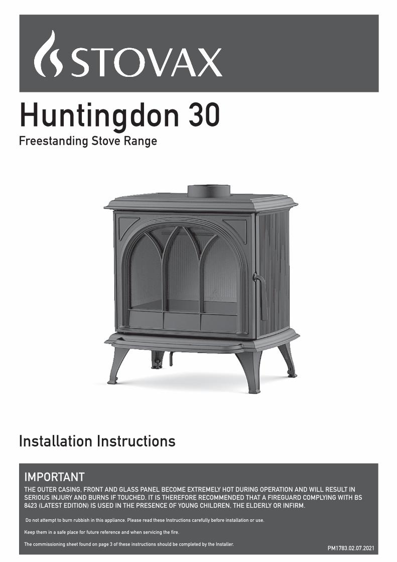
Huntingdon 30Freestanding Stove Range
Installation Instructions
IMPORTANTTHE OUTER CASING, FRONT AND GLASS PANEL BECOME EXTREMELY HOT DURING OPERATION AND WILL RESULT IN SERIOUS INJURY AND BURNS IF TOUCHED. IT IS THEREFORE RECOMMENDED THAT A FIREGUARD COMPLYING WITH BS 8423 (LATEST EDITION) IS USED IN THE PRESENCE OF YOUNG CHILDREN, THE ELDERLY OR INFIRM. Do not attempt to burn rubbish in this appliance. Please read these Instructions carefully before installation or use.
Keep them in a safe place for future reference and when servicing the fire.
The commissioning sheet found on page 3 of these instructions should be completed by the Installer.PM1783.02.07.2021

2
Covering the following models:Huntingdon 30 Range
Installation Instructions ............................................4
Essential Information .................................................................. 4
Dimensions .................................................................................7
Distance to Combustibles........................................................... 9
Pre-installation .......................................................................... 11
Installation ................................................................................16
Commissioning .........................................................................20
Maintenance & Servicing ........................................21
Servicing ...................................................................................21
Legal Requirements ................................................................. 24
Exploded Parts .........................................................................26
Information Requirement - Solid Fuel .....................................28
Service Records .......................................................................29
CONTENTS
MODEL WOOD MULTI- FUELHuntingdon 30 Clear Door 701-068 701-473Huntingdon 30 Tracery Door 701-042 701-496
CONSUMER SUPPORT VIDEO:www.stovax.tv/support/Huntingdon

3
Dealer appliance was purchased from:
Name:
Address:
Telephone number:
Essential information - MUST be completed:
Date Installed:
Model Description:
Serial Number:
Installation Engineer:
Company Name:
Address:
Telephone number:
Commissioning Checks - to be completed and signed:
Is flue system correct for the appliance: YES NO
Flue swept and soundness test complete: YES NO
Smoke test completed on installed appliance YES NO
Spillage test completed YES NO
Use of appliance and operation of controls explained YES NO
Clearance to combustible materials checked YES NO
Instruction book handed to customer YES NO
CO Alarm Fitted YES NO
Flue draught Reading (Pa) HOT COLD
Signature: ............................................................................ Print Name: ..........................................................................
To assist us in any guarantee claim please complete the following information:-
APPLIANCE COMMISSIONING SHEET

4
ESSENTIAL INFORMATION - MULTI-FUEL STOVE
GENE
RAL
Model:
Hun
tingd
on 3
0
Nominal Heat OutputWood kW 5.0
Solid Fuel kW 5.0
EfficiencyWood % 81.6
Solid Fuel % 82.0
CO @ 13% O2Wood % 0.10
Solid Fuel % 0.09
Weight Kg 93.5
Recommended FuelsWood Seasoned Wood (less than 20% moisture content)
Solid Fuel Briquette smokeless fuel suitable for closed appliances (Ancit-Phuracite-Maxibrite-Taybrite-Homefire Ovals)
As tested to the requirements of EN 13240 for intermittent operation
FLUE
S
Flue/Chimney Size
Without flue liner Round (Diameter)mm 128
inch 5
Without flue liner system (Square)mm 135
inch 5½
With Liner of Factory made system (diameter) installed in accordance with
manufacturers instructions
mm 128
inch 5
Flue/Chimney minimum height**
All products**must be 4.5m from the hearth to the top of the flue, with no horizontal sections and a maximum of 4 bends. Bends must have angles of less than 45 degrees from the
vertical.
m 4.5
feet 15
Flue Draught
Min
Pa
10
Nominal 12
Max 20
Flue Gas Mass FlowWood g/s 3.8
Solid Fuel g/s 3.0
Average Flue Gas Temperature
Wood oC 267
Solid Fuel oC 289
Flue Outlet Size(Top or Rear Option)
Allmm 128
inch 5
European Min Spec for Chimney Flue - T400 N2 D 3 G50
VENT
ILAT
ION
A) Traditionally Built Homes• Where leakage is greater than 5m3/hour/m2.• Ventilation normally required = 550mm2 per kW output over 5kW
B) Modern Construction Homes• Where leakage is less than 5m3/hour/m2.• Ventilation normally required = 550mm2 per kW
A Additional Ventilation
mm2 n/a
cm2 n/a
in2 n/a
B Additional Ventilation
mm2 2750
cm2 27.50
in2 4.3
For full technical details on ventilation see Technical Appendix on Page 25

5
ESSENTIAL INFORMATION - WOOD STOVE
GENE
RAL
Model:
Hun
tingd
on 3
0
Nominal Heat Output Wood kW 5.0
Efficiency Wood % 82.7
CO @ 13% O2 Wood % 0.09
Weight Wood Kg 91
Recommended Fuels Wood Seasoned Wood (less than 20% moisture content)
As tested to the requirements of EN 13240 for intermittent operation
FLUE
S
Flue/Chimney SizeMay be reduced to 128mm (5") if burning approved smokeless fuels or burning wood in an appliance approved for use in a DEFRA smoke control area
Without flue liner Round (Diameter)mm 128
inch 5
Without flue liner system (Square)mm 135
inch 5½
With Liner of Factory made system (diameter) installed in accordance with
manufacturers instructions
mm 128
inch 5
Flue/Chimney minimum height**
All products**must be 4.5m from the hearth to the top of the flue, with no horizontal sections and a maximum of 4 bends. Bends must have angles of less than 45 degrees from the
vertical.
m 4.5
feet 15
Flue Draught
Min
Pa
10
Nominal 12
Max 20
Flue Gas Mass Flow Wood g/s 3.7
Average Flue Gas Temperature
Wood oC 260
Flue Outlet Size(Top or Rear Option)
Allmm 128
inch 5
European Min Spec for Chimney Flue - T400 N2 D 3 G50
VENT
ILAT
ION
A) Traditionally Built Homes• Where leakage is greater than 5m3/hour/m2.• Ventilation normally required = 550mm2 per kW output over 5kW
B) Modern Construction Homes• Where leakage is less than 5m3/hour/m2.• Ventilation normally required = 550mm2 per kW
A Additional Ventilation
mm2 n/a
cm2 n/a
in2 n/a
B Additional Ventilation
mm2 2750
cm2 27.50
in2 4.3
For full technical details on ventilation see Technical Appendix on Page 25
6
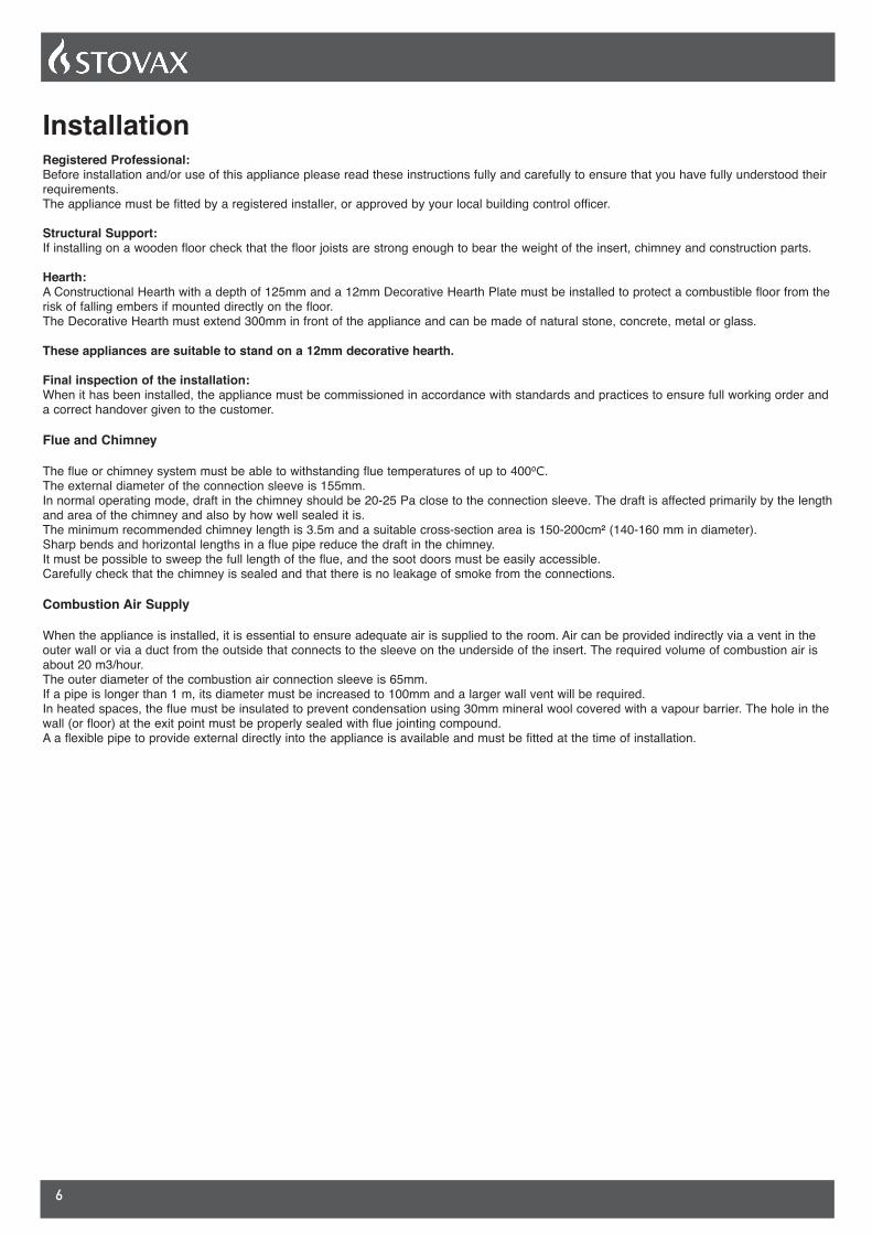
InstallationRegistered Professional:Before installation and/or use of this appliance please read these instructions fully and carefully to ensure that you have fully understood their requirements. The appliance must be fitted by a registered installer, or approved by your local building control officer.
Structural Support:If installing on a wooden floor check that the floor joists are strong enough to bear the weight of the insert, chimney and construction parts.
Hearth:A Constructional Hearth with a depth of 125mm and a 12mm Decorative Hearth Plate must be installed to protect a combustible floor from the risk of falling embers if mounted directly on the floor.The Decorative Hearth must extend 300mm in front of the appliance and can be made of natural stone, concrete, metal or glass.
These appliances are suitable to stand on a 12mm decorative hearth.
Final inspection of the installation:When it has been installed, the appliance must be commissioned in accordance with standards and practices to ensure full working order and a correct handover given to the customer.
Flue and Chimney
The flue or chimney system must be able to withstanding flue temperatures of up to 4000C.The external diameter of the connection sleeve is 155mm.In normal operating mode, draft in the chimney should be 20-25 Pa close to the connection sleeve. The draft is affected primarily by the length and area of the chimney and also by how well sealed it is.The minimum recommended chimney length is 3.5m and a suitable cross-section area is 150-200cm² (140-160 mm in diameter).Sharp bends and horizontal lengths in a flue pipe reduce the draft in the chimney. It must be possible to sweep the full length of the flue, and the soot doors must be easily accessible.Carefully check that the chimney is sealed and that there is no leakage of smoke from the connections.
Combustion Air Supply
When the appliance is installed, it is essential to ensure adequate air is supplied to the room. Air can be provided indirectly via a vent in the outer wall or via a duct from the outside that connects to the sleeve on the underside of the insert. The required volume of combustion air is about 20 m3/hour.The outer diameter of the combustion air connection sleeve is 65mm.If a pipe is longer than 1 m, its diameter must be increased to 100mm and a larger wall vent will be required.In heated spaces, the flue must be insulated to prevent condensation using 30mm mineral wool covered with a vapour barrier. The hole in the wall (or floor) at the exit point must be properly sealed with flue jointing compound.A a flexible pipe to provide external directly into the appliance is available and must be fitted at the time of installation.

7
HUNTINGDON DIMENSIONS
All dimensions in mm (25.4 mm = 1”)
AA1
(GLASS VIEWING
AREA)
BB1
(GLASS VIEWING
AREA)
C D E F G H I J K L
552 367 602 253 520 383 602 622 670 221 130 150 128 150
KJ
B1
I
B
A
C
A1
HUNTINGDON 30
H
E F
L
G
D
8
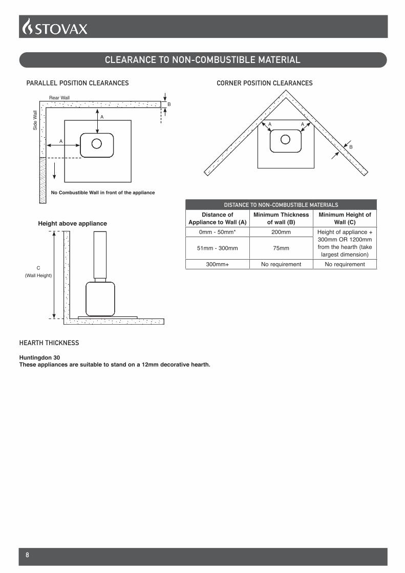
CLEARANCE TO NON-COMBUSTIBLE MATERIAL
Rear Wall
Side
Wal
l
B
A
A
PARALLEL POSITION CLEARANCES
No Combustible Wall in front of the appliance
CORNER POSITION CLEARANCES
B
AA
Height above appliance
C(Wall Height)
DISTANCE TO NON-COMBUSTIBLE MATERIALSDistance of
Appliance to Wall (A)Minimum Thickness
of wall (B)Minimum Height of
Wall (C)0mm - 50mm* 200mm Height of appliance +
300mm OR 1200mm from the hearth (take
largest dimension)51mm - 300mm 75mm
300mm+ No requirement No requirement
HEARTH THICKNESS
Huntingdon 30These appliances are suitable to stand on a 12mm decorative hearth.

9
CLEARANCE TO COMBUSTIBLE MATERIAL
A
B
D
CC
OPEN SETTING
ENCLOSED SETTING
A
B
C C
A
D
DIMENSION A B CD
Heat Shield No Flue Spigot Heat Shield
Huntingdon 30 - Wood 1259 300 225 75 225
Huntingdon 30 - Multi-Fuel 1259 250 150 75 175
DIMENSION A B C
D
Heat Shield No Flue Spigot Heat Shield
Huntingdon 30 - Wood 1009 300 200 75 225
Huntingdon 30 - Multi-Fuel 959 250 200 75 175

10
OPTIONAL EXTRAS
EXTERNAL AIR CONNECTIONThis appliance can be fitted with an optional kit to help bring air directly into the appliance from outside. For installation and operating procedures see Page 19.
APPLIANCE PART NO.
Huntingdon 30 998-080
TWIN WALL HEAT SHIELD(TWIN WALL INSTALLATIONS ONLY)
IF THE APPLIANCE IS TO BE INSTALLED IN A COMBUSTIBLE SETTING THE MINIMUM CLEARANCES CAN ONLY BE ACHIEVED USING A TWIN WALL FLUE SYSTEM AND HEAT SHIELD.
Align the Heat Shield on the slots to cover the gap between the Twin Wall and the Top Plate. The overlap must be at least 10mm.
Twin Wall Flue
Connector Adapter
HeatShield
10mmMinimum
IMPORTANTWhen installing the flue pipe, there must be no exposed single wall flue, & a minimum 10mm expansion gap must be left between the Twin Wall flue & the top face of the Top Plate.

11
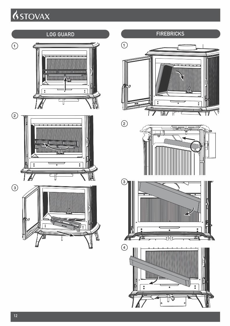
PRE-INSTALLATIONTo make the installation of the appliance easier it is best to remove the internal components before installation.
OPENING THE DOOR
1
2
3
4
5
6
12
LOG GUARD
1
2
3
FIREBRICKS
1
2
3
4

13
5
6
7
WOODBURNING GRATE
1
2
3
4

14
MULTI-FUEL GRATE
1
2
3
4
5
6
7
8

15
9
16
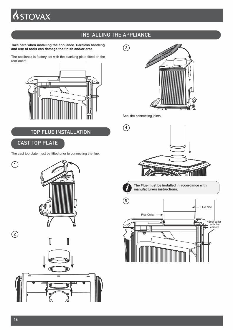
INSTALLING THE APPLIANCETake care when installing the appliance. Careless handling and use of tools can damage the finish and/or area.
The appliance is factory set with the blanking plate fitted on the rear outlet.
TOP FLUE INSTALLATION
CAST TOP PLATE
The cast top plate must be fitted prior to connecting the flue.
1
2
3
Seal the connecting joints.
4
The Flue must be installed in accordance with manufacturers instructions.
Flue pipe
Flue Collar
Seal collar with fire cement
5
17
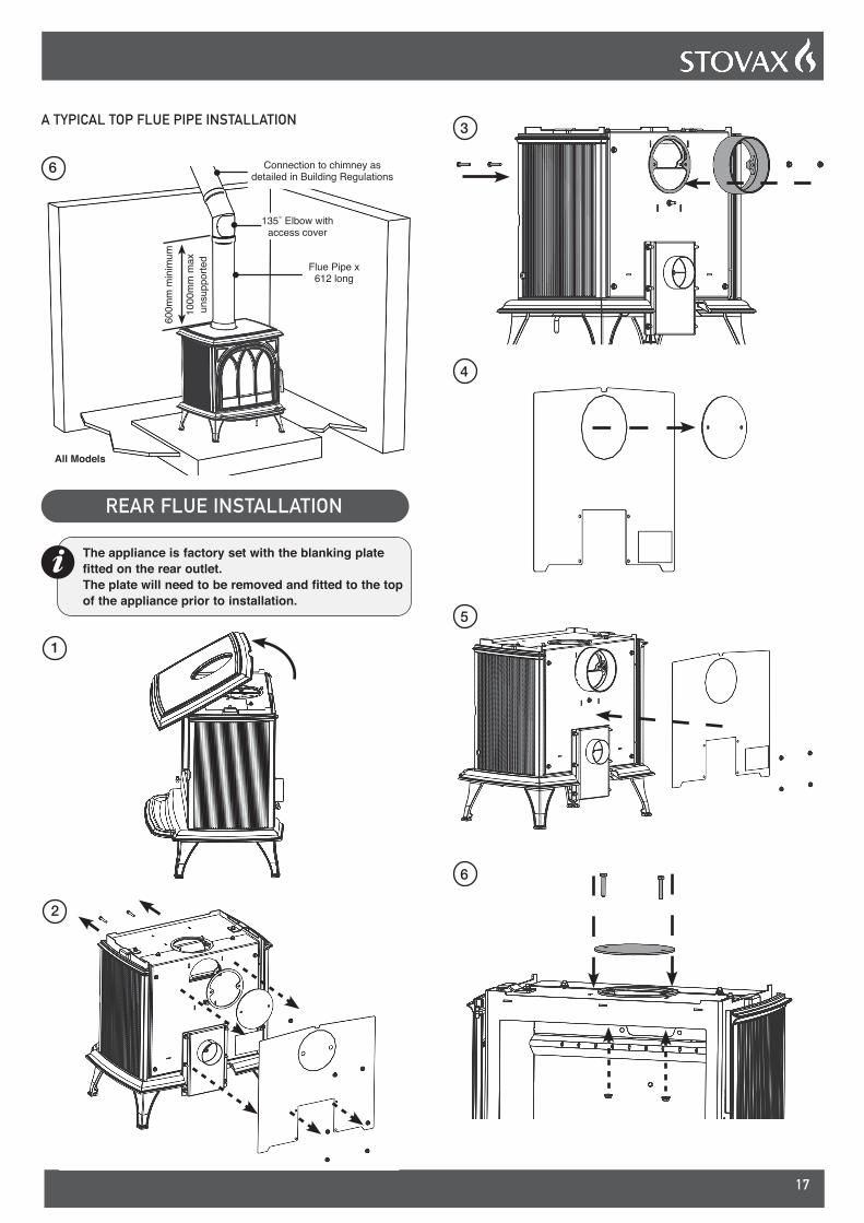
A TYPICAL TOP FLUE PIPE INSTALLATION
Connection to chimney as detailed in Building Regulations
135˚ Elbow with access cover
Flue Pipe x 612 long
600m
m m
inim
um
1000
mm
max
un
supp
orte
d
All Models
6
REAR FLUE INSTALLATION
The appliance is factory set with the blanking plate fitted on the rear outlet. The plate will need to be removed and fitted to the top of the appliance prior to installation.
1
2
3
4
5
6

18
7
Cast Top Plate Blanking Plate
M6 BoltM6 Bolt
Flue Collar
M6 Nut
M6 NutM6 Nut
8
The following flue pipe is available to ensure safe installation:
5" TEE Stovax Product Code 4516
5" 135O BEND Stovax Product Code 4512
5" FLUE PIPE X 612MM LONG Stovax Product Code 4501
Tee with cap
Cap
Seal collar with fire cement
Self-tapping screw( 1 side only )
9
A TYPICAL REAR FLUE PIPE INSTALLATION
135˚ Elbow with access cover
All modelsConnection to chimney as detailed in Building
Regulations
Flue pipe x 612 long
600m
m m
inim
um
600m
m m
inim
um
1000
mm
max
un
supp
orte
d
10
Replace internal components.
FLUE PULL TEST POINT
1
2

19
EXTERNAL AIR CONNECTIONThis appliance can be fitted with an optional kit to help bring air directly into the appliance from outside.
APPLIANCE PART NO.
Huntingdon 30 998-080
1
2
CO ALARMSAll open flued appliances can be affected by temporary atmospheric conditions which may allow fumes to enter the house. Building regulations require that whenever a new or replacement fixed solid fuel or wood/biomass appliance is installed in a dwelling a carbon monoxide alarm, complying with BS EN50291, must be fitted in the same room as the appliance. Further guidance on the installation of the carbon monoxide alarm is available in the latest edition of BS EN50292 and from the alarm manufacturer's instructions.
HETAS recommend the unit is permanently fixed in accordance with the manufacturer's installation instructions or with the guidance contained in Approved Document J where no other information is available.
Provision of an alarm must not be considered a substitute for either installing the appliance correctly or ensuring regular servicing and maintenance of the appliance and chimney

20
COMMISSIONING
To commission: — Replace the internal components.
— Check the door alignment and catch operation and adjust if required.
— Check the soundness of door seals, castings and joints.
— Check the operation of the air controls.
Now carry out a final smoke draw test: — Warm the flue with a blowlamp, or similar, for about 10
minutes. — Place a smoke pellet on the centre of the grate, with the
air controls open. — Close the door. Smoke should now be drawn up the flue
and be seen to exit from the flue terminal. — Complete test with all doors and windows closed in the
room where the appliance is fitted.
— If there are any extractor fans in adjacent rooms the test must be repeated with the fans running on maximum and with interconnecting doors open.
— Check the effect of ceiling fans during the test.
If excessive spillage occurs allow the appliance to cool and re-check the flue system and ventilation.
Finally: — Explain to the user the correct operation of the
appliance, use of the controls and the importance of only using suitable fuels in order to reduce smoke emissions - particularly if they live in a Smoke Control Area.
— Ensure that a CO alarm has been fitted and make the user aware of its operation and importance, referring them to the Warning section on page 5 of the User Instructions.
— Explain the cleaning and routine maintenance requirements.
— Explain the requirement to use a suitable fireguard when children, elderly or infirm persons are near the appliance.
— Record retailer/supplier and installer details in Appliance Commissioning Checklist.
— Record serial number in Appliance Commissioning Checklist.
This number is required when ordering spare parts and making warranty claims.
— Give this instruction manual to the customer.
21
SERVICING
For a complete list of spare parts and accessories contact your Stovax Retailer, visit www.stovaxspares.com or call 01392 474011.
Before the start of the heating season strip, inspect and clean the appliance as detailed:
— Allow appliance to cool. — Remove all internal parts: baffle, log guard, cast bases and firebricks.
Take care handling firebricks as they can become fragile after a period of use. — Sweep the appliance at this point if necessary.
— Vacuum clean any remaining ash and debris from the inside of the appliance.
— Check the parts for any damage. Replace any damaged parts using genuine Stovax replacements parts.
— Check and clean the firebricks with a soft brush. Some surface damage will occur during use. The life of the bricks will depend on the type of fuels burnt and the level of use. Replace damaged bricks as soon as possible. — Re-fit cleaned internal parts.
— Use Stovax Glass.
Do not use abrasive cleaners to remove tar or soot deposits from the glass.
— Fit new door rope seal.
— Lightly oil the door catch mechanism and hinge pins. Avoid getting oil onto the door seals and glass.
— To refresh painted finishes a touch up spray is available. Contact your Stovax retailer quoting the serial number found on the appliance data badge.
Use genuine Stovax replacement parts to keep the appliance in safe, efficient working order. This is a list of the maintenance products thatmay need be required:
Products to assist in the cleaning and maintenance of your Huntingdon are available online at www.stovax.com or from your local Stovax dealer which, along with regular maintenance and use of correct fuels, will keep the appliance in the best possible condition.
For more information about the Stovax Group products please visit our web site at www.stovax.com
Burn at a low temperature for the first day of use after any maintenance. This allows the seals, fixing glues and paint to fully cure.
During this time the appliance may give off some unpleasant odours. Keep the room well ventilated to avoid a build-up of fumes.
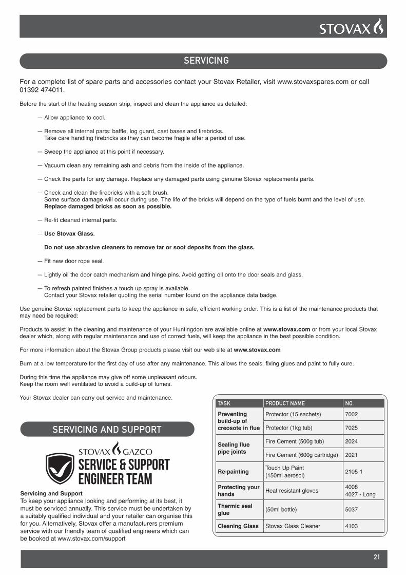
Your Stovax dealer can carry out service and maintenance.TASK PRODUCT NAME NO.
Preventing build-up of creosote in flue
Protector (15 sachets) 7002
Protector (1kg tub) 7025
Sealing flue pipe joints
Fire Cement (500g tub) 2024
Fire Cement (600g cartridge) 2021
Re-painting Touch Up Paint(150ml aerosol) 2105-1
Protecting your hands Heat resistant gloves 4008
4027 - Long
Thermic seal glue (50ml bottle) 5037
Cleaning Glass Stovax Glass Cleaner 4103
SERVICING AND SUPPORT
Servicing and SupportTo keep your appliance looking and performing at its best, it must be serviced annually. This service must be undertaken by a suitably qualified individual and your retailer can organise this for you. Alternatively, Stovax offer a manufacturers premium service with our friendly team of qualified engineers which can be booked at www.stovax.com/support
22
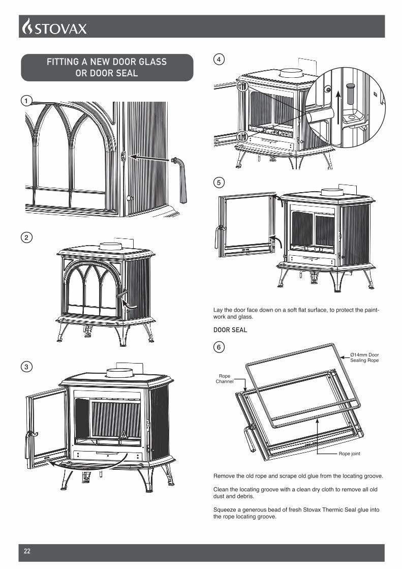
FITTING A NEW DOOR GLASS OR DOOR SEAL
1
2
3
4
5
Lay the door face down on a soft flat surface, to protect the paint-work and glass.
DOOR SEAL
Rope Channel
Ø14mm Door Sealing Rope
Rope joint
6
Remove the old rope and scrape old glue from the locating groove.
Clean the locating groove with a clean dry cloth to remove all old dust and debris.
Squeeze a generous bead of fresh Stovax Thermic Seal glue into the rope locating groove.

23
Press the new Stovax rope into the locating groove, placing the joint in the middle of the lower edge of the door,
DOOR GLASS
USING THE APPLIANCE WITH A DAMAGED DOOR GLASS COULD CAUSE DANGEROUS FUMES TO ENTER THE ROOM, OR THE APPLIANCE TO OVER-FIRE, RESULTING IN DAMAGE.
7
Take note of the roping around the edge of the door glass around the edge. This will also need replacing.
Dispose of the old glass safely.
ADJUSTING THE DOOR CATCH
1
2
3
Fully tighten the nuts to secure the Catch.
Open and close the door several times to the check the adjustment.
FINAL CHECKSFollowing these adjustments check that the door:
— Does not come into contact with the log guard. — Passes the paper sealing test. — Aligns with the sides and top of the appliance.

24
LEGAL REQUIREMENTSBefore installation and/or use of this appliance please read these instructions carefully to ensure that all requirements are fully understood.
The appliance must be fitted by a registered installer, or approved by your local building control officer.
It is very important to understand the requirements of the national Building Regulations and standards, along with any local regulations and working practices that may apply. Should any conflict occur between these instructions and these regulations then the regulations must apply.
Your local Building Control Office can advise regarding the requirements of the regulations.
Works must be carried out with care to meet the requirements of Health and Safety and comply with the Health and Safety rules, and any new regulations introduced during the lifetime of these instructions. Particular attention should be drawn to:
— Handling: The appliance is heavy. Adequate facilitie must be available for loading, unloading and on site handling. — Fire Cement: Some fire cement is caustic and must not come into contact with the skin. Protective gloves must be worn. Wash hands thoroughly with plenty of water after contact with skin. — Asbestos: This appliance contains no asbestos. If there is the possibility of disturbing any asbestos in the course of installation seek specialist guidance and use appropriate equipment. — Metal Parts: Take care when installing or servicing the stove to avoid personal injury.
A faulty installation can cause danger to the inhabitants and structure of the building.
For users of this appliance:Your building insurance company may require you to inform them that a new heating appliance has been installed on your property. Check that your cover is still valid after installing the appliance.
FLUE OR CHIMNEYThe flue or chimney system must be in good condition.It must be inspected by a competent person and passed for use with the appliance before installation.
Products of combustion entering the room can cause serious health risks.
The following must be checked:
— The construction of the masonry chimneys, flue block chimneys and connecting flue pipe system must meet the requirements of the Building Regulations.
— A flexible flue liner system can be used if certified for use with solid fuel systems and installation complies with
manufacturer’s instructions and Building Regulations. The flue liner must be replaced when an appliance is replaced, unless proven to be recently installed and in good condition.
— If it is necessary to fit a register plate it must conform to the Building Regulations. — The minimum height of the flue or chimney must be 4.5m from the hearth to the top of the flue, with no horizontal sections and a maximum of 4 bends. Bends must have angles of less than 45 degrees from the vertical.
— There should be at least 600mm of vertical flue pipe above the appliance before any bends are introduced.
— Ensure the connecting flue pipe is kept a suitable distance from any combustible material and does not form part of the supporting structure of the building.
— The installer must ensure the flue pipe diameter is not less than the diameter of the outlet of the appliance and does not narrow to less than the size of the outlet at any point in the system.
— Make provision to remove the appliance without the need to dismantle the chimney.
— Any existing flue must be confirmed as suitable for the new intended use as defined in the Building Regulations.
— The flue or chimney systems must be inspected and swept to confirm the system is structurally sound and free from obstructions.
— If the chimney is believed to have previously served an open fire it must be swept a second time within a month of regular use after installation to clear any soot falls that may have occurred due to difference in combustion levels.
— The flue exit from the building must comply with local building control rules.
— Chimney heights and/or separations may need to be increased in particular cases where wind exposure, surrounding tall buildings, high trees or high ground could have adverse effects on flue draught.
— Do not connect or share the flue or chimney system with another heating appliance.
Do not connect to systems containing large voids or spaces over 230mm square.
Suitable access must be provided to enable the collection and removal of debris.
The flue must be swept and inspected when the appliance is installed.
Flue Draught
The flue draught must be checked with all windows and doors closed and any extraction fans in this, or adjoining rooms, running at maximum speed (see Installation Checklist for ventilation requirements).
TWIN WALL FLUE SYSTEMIf this appliance is to be used in conjunction with a twin wall flue system then Stovax recommend the use of their Professional XQ range. Details of this product are available from your Stovax retailer.
25
VENTILATIONMany older buildings are sufficiently ventilated by natural leakage of air to provide suitable air supply for an appliance of 5kW output or less. Modern building techniques have reduced the amount of air that leaks in or out of a house. A modern construction with an air tightness of less than 5m3 per hour per m2 requires an air vent for ALL solid fuel appliances including those with a rated heat output of less than 5kW.
NOTE: The air leakage of a modern house is tested at the completion of construction and a certificate issued confirming this.
This appliance requires a constant supply of air to maintain proper combustion and effective flue performance.
An inadequate air supply can result in poor combustion and smoke entering the room which is potentially dangerous.
This supply of air can come from either:
— Purpose provided ventilation. — Some Stovax appliances can also be fitted with an optional outdoor air kit which allows air to be drawn in from the outside. The amount of air required must comply with local building regulations and the rules in force.
If spillage is detected during commissioning then there may be insufficient natural ventilation and an additional air supply will be necessary.
Permanent air vents should be non-adjustable and positioned where they are unlikely to be become blocked.
If vents open into adjoining rooms or spaces there must be an air vent of at least the same size direct to the outside.
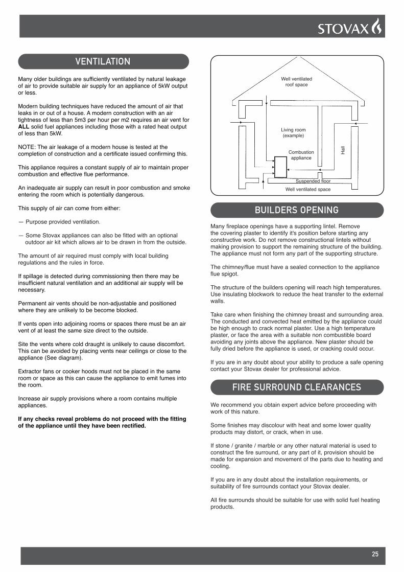
Site the vents where cold draught is unlikely to cause discomfort. This can be avoided by placing vents near ceilings or close to the appliance (See diagram).
Extractor fans or cooker hoods must not be placed in the same room or space as this can cause the appliance to emit fumes into the room.
Increase air supply provisions where a room contains multiple appliances.
If any checks reveal problems do not proceed with the fitting of the appliance until they have been rectified.
Well ventilated roof space
Living room (example)
Hal
l
Well ventilated spaceSuspended floor
Combustion appliance
BUILDERS OPENINGMany fireplace openings have a supporting lintel. Remove the covering plaster to identify it's position before starting any constructive work. Do not remove constructional lintels without making provision to support the remaining structure of the building. The appliance must not form any part of the supporting structure.
The chimney/flue must have a sealed connection to the appliance flue spigot.
The structure of the builders opening will reach high temperatures. Use insulating blockwork to reduce the heat transfer to the external walls.
Take care when finishing the chimney breast and surrounding area. The conducted and convected heat emitted by the appliance could be high enough to crack normal plaster. Use a high temperature plaster, or face the area with a suitable non combustible board avoiding any joints above the appliance. New plaster should be fully dried before the appliance is used, or cracking could occur.
If you are in any doubt about your ability to produce a safe opening contact your Stovax dealer for professional advice.
FIRE SURROUND CLEARANCESWe recommend you obtain expert advice before proceeding with work of this nature.
Some finishes may discolour with heat and some lower quality products may distort, or crack, when in use.
If stone / granite / marble or any other natural material is used to construct the fire surround, or any part of it, provision should be made for expansion and movement of the parts due to heating and cooling.
If you are in any doubt about the installation requirements, or suitability of fire surrounds contact your Stovax dealer.
All fire surrounds should be suitable for use with solid fuel heating products.

26
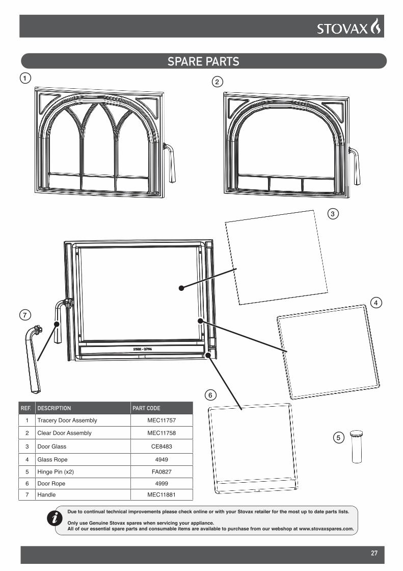
SPARE PARTS
REF. DESCRIPTION PART CODE
1 Brick Set MEC11843
2a Multi-Fuel Grate(Multi-fuel models only) CA7950
2b Wood Burning Tray(Wood Burning models only) CA7953
3 Log Guard CA7940
4 Ashpan(Multi-fuel models only) MEC11746
Due to continual technical improvements please check online or with your Stovax retailer for the most up to date parts lists.
Only use Genuine Stovax spares when servicing your appliance. All of our essential spare parts and consumable items are available to purchase from our webshop at www.stovaxspares.com.
1
3
4
2a
2b
Multi-fuel model pictured
27
Due to continual technical improvements please check online or with your Stovax retailer for the most up to date parts lists.
Only use Genuine Stovax spares when servicing your appliance. All of our essential spare parts and consumable items are available to purchase from our webshop at www.stovaxspares.com.
SPARE PARTS1 2
REF. DESCRIPTION PART CODE
1 Tracery Door Assembly MEC11757
2 Clear Door Assembly MEC11758
3 Door Glass CE8483
4 Glass Rope 4949
5 Hinge Pin (x2) FA0827
6 Door Rope 4999
7 Handle MEC11881
3
4
6
7
5
28
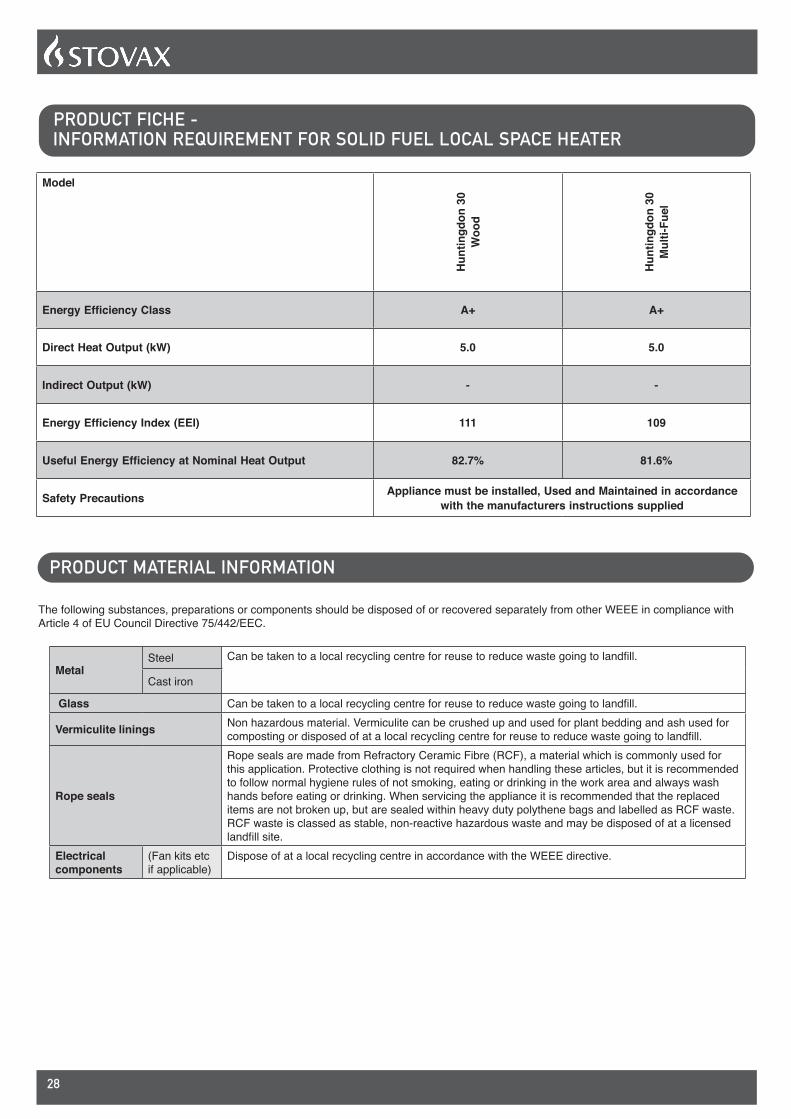
PRODUCT FICHE - INFORMATION REQUIREMENT FOR SOLID FUEL LOCAL SPACE HEATER
Model
Hun
tingd
on 3
0 W
ood
Hun
tingd
on 3
0 M
ulti-
Fuel
Energy Efficiency Class A+ A+
Direct Heat Output (kW) 5.0 5.0
Indirect Output (kW) - -
Energy Efficiency Index (EEI) 111 109
Useful Energy Efficiency at Nominal Heat Output 82.7% 81.6%
Safety Precautions Appliance must be installed, Used and Maintained in accordance with the manufacturers instructions supplied
The following substances, preparations or components should be disposed of or recovered separately from other WEEE in compliance with Article 4 of EU Council Directive 75/442/EEC.
MetalSteel Can be taken to a local recycling centre for reuse to reduce waste going to landfill.
Cast iron
Glass Can be taken to a local recycling centre for reuse to reduce waste going to landfill.
Vermiculite linings Non hazardous material. Vermiculite can be crushed up and used for plant bedding and ash used for composting or disposed of at a local recycling centre for reuse to reduce waste going to landfill.
Rope seals
Rope seals are made from Refractory Ceramic Fibre (RCF), a material which is commonly used for this application. Protective clothing is not required when handling these articles, but it is recommended to follow normal hygiene rules of not smoking, eating or drinking in the work area and always wash hands before eating or drinking. When servicing the appliance it is recommended that the replaced items are not broken up, but are sealed within heavy duty polythene bags and labelled as RCF waste. RCF waste is classed as stable, non-reactive hazardous waste and may be disposed of at a licensed landfill site.
Electrical components
(Fan kits etc if applicable)
Dispose of at a local recycling centre in accordance with the WEEE directive.
PRODUCT MATERIAL INFORMATION
29
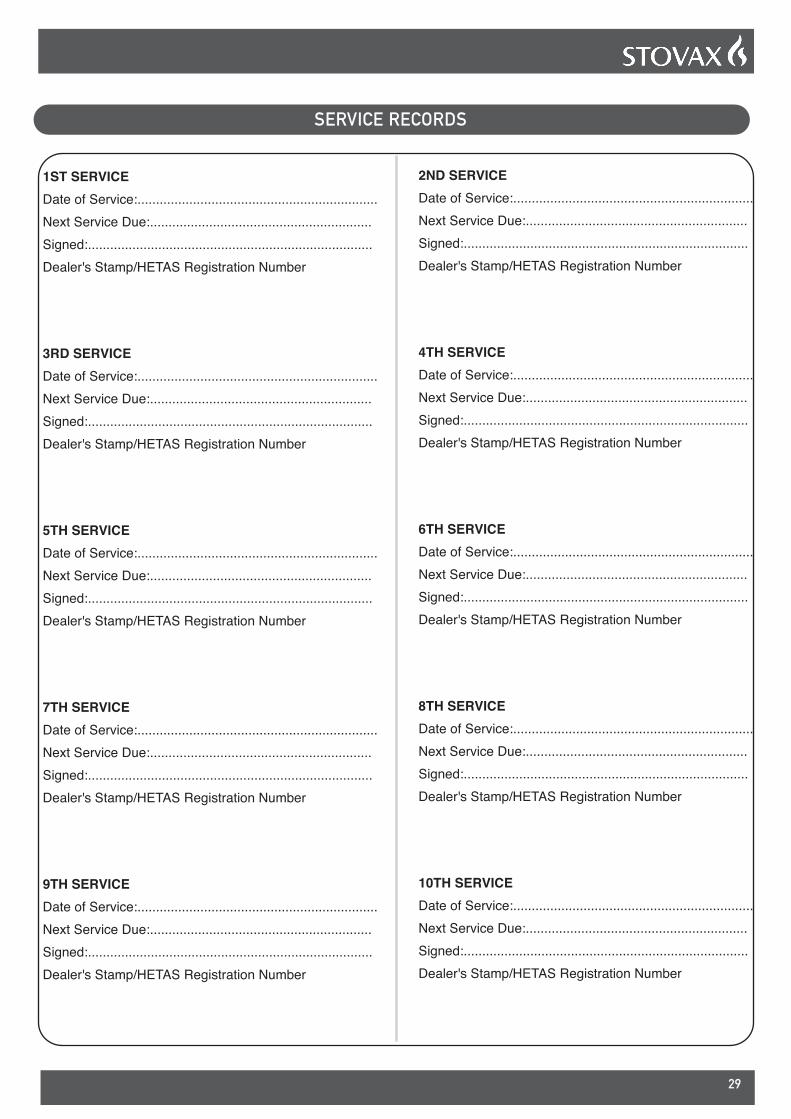
SERVICE RECORDS
1ST SERVICEDate of Service:.................................................................Next Service Due:............................................................Signed:.............................................................................Dealer's Stamp/HETAS Registration Number
3RD SERVICEDate of Service:.................................................................Next Service Due:............................................................Signed:.............................................................................Dealer's Stamp/HETAS Registration Number
5TH SERVICEDate of Service:.................................................................Next Service Due:............................................................Signed:.............................................................................Dealer's Stamp/HETAS Registration Number
7TH SERVICEDate of Service:.................................................................Next Service Due:............................................................Signed:.............................................................................Dealer's Stamp/HETAS Registration Number
9TH SERVICEDate of Service:.................................................................Next Service Due:............................................................Signed:.............................................................................Dealer's Stamp/HETAS Registration Number
2ND SERVICEDate of Service:.................................................................Next Service Due:............................................................Signed:.............................................................................Dealer's Stamp/HETAS Registration Number
4TH SERVICEDate of Service:.................................................................Next Service Due:............................................................Signed:.............................................................................Dealer's Stamp/HETAS Registration Number
6TH SERVICEDate of Service:.................................................................Next Service Due:............................................................Signed:.............................................................................Dealer's Stamp/HETAS Registration Number
8TH SERVICEDate of Service:.................................................................Next Service Due:............................................................Signed:.............................................................................Dealer's Stamp/HETAS Registration Number
10TH SERVICEDate of Service:.................................................................Next Service Due:............................................................Signed:.............................................................................Dealer's Stamp/HETAS Registration Number


*PRPM1783*PM1783
FOR ENQUIRIES IN THE U.K (EXCLUDING NI):
Stovax Ltd, Osprey Road, Sowton Industrial Estate, Exeter, Devon, England EX2 7JG
Tel: (01392) 474011 E-mail: [email protected] www.stovax.com
FOR ENQUIRIES IN EUROPE (INCLUDING NI):
Stovax Heating Group (NI) Ltd (Comp reg NI675194), 40 Linenhall Street, Belfast, BT2
8BA DX 400 NR Belfast Tel: +44 (0)1392 261990 E-mail: [email protected]
E & O E