Embed Size (px)
Citation preview

HumeDeck® bridge systemInstallation guide

This guide is of a general nature only and should be
read in conjunction with project-specific documents
including the contract, project specifications and
project drawings. This guide is not a substitute for the
project documentation.
For typical installation requirements please refer to the
Humes general assembly standard drawings or Humes
project-specific drawings. The Humes drawings contained
in this document are system assembly drawings only and
do not constitute a site layout; the site layout should be
specified in project documents provided by the consulting
engineer who has been engaged by the asset owner.
Where the contents of this guide differ from project
specifications and drawings, supervisory personnel
should consult with a Humes engineer. In the event
of any conflict between the information in this guide
and local legislative requirements, the legislative
requirements will take precedence.
It is the responsibility of the site owner and its
contractors and consulting engineers to determine the
site’s suitability for construction, including access for
plant and other issues.
No statement in this guide is to be construed as a
guarantee or warranty.
Purpose of this guide
This guide outlines the construction procedures and requirements for the
installation of the HumeDeck® bridge system. This document should be reviewed by
supervisory personnel prior to commencing any HumeDeck® system installation.

HumeDeck® modular bridge system 2
Other bridge systems 2
Specifications 3
HumeDeck® system components 3
Handling and installation 6
Safety recommendations 6
Pre-delivery 7
Site meeting 7
Delivery 7
Lifting 8
Bridge installation 9
Critical dimensions 9
Install and position piles 10
Place headstocks and abutments 11
Install hold down bolts 12
Attach elastomeric pads 13
Complete deck jointing (if required) 14
Place and fix barriers, rails and kerbs 15
Concrete barrier fixing 15
Rail barrier fixing 16
Kerb fixing 17
Appendix 1 – HumeDeck® unit
installation checklist
18
Appendix 2 – Bracket fixing procedure 20
Contact information 21
Contents

Bottom:HumeDeck® modular bridge system installation including deck units, precast piles, abutments and headstocks
2 HumeDeck® bridge system
The HumeDeck® bridge system is a cost effective
decking system with fast and simple installation and
requires minimal maintenance:
• The deck and girders are combined into one unit to
enable efficient design and fast and simple installation.
The combined deck and girder unit provides a span
from 6 m to 12 m.
• Headstocks and abutments are either fixed to piles or
bolted to existing piers for faster installation.
• Minimal longitudinal joints reduce installation time
and maintenance requirements.
• It is efficient to transport and handle.
• Site work is reduced as post tensioning of
units is not necessary.
• The top surface of the HumeDeck® units have a coarse
broom finish which can be used as the road surface
without the need for additional concrete topping or
asphalt surfacing.
The standard HumeDeck® bridge system has a design life
of 100 years, in accordance with the Australian Standard
– Bridge Design (AS 5100 – 2004).
Bridge units can be designed to meet site-specific
parameters and tolerances and can also incorporate
cast-in fittings for the connection of different types and
classes of barriers. Kerbs can be precast integrally with
the HumeDeck® units or manufactured as separate
precast units and bolted to the deck units on site.
Other bridge systems
Humes provide a wide range of bridging and platform
solutions including precast arches, large box culverts,
precast modular beams, planks and decking units, and
prestressed concrete bridge components.
The flexibility of Humes’ bridge solutions allows for the
easy adaptation of standard unit sections, providing
a choice of geometric envelopes to meet access and
waterway requirements from 2 m to 38 m span.
We pride ourselves on delivering customised solutions
to maximize installation, performance, and budgetary
outcomes for our clients.
HumeDeck® modular bridge system
The HumeDeck® bridge system is a modular precast solution for bridges spanning
6 m to 12 m. It is suitable for installation onto an existing or new substructure, or
can be combined with precast concrete piles, abutments and headstocks to achieve
a total precast solution.

HumeDeck® system components
Table 1 – Superstructure components
Deck and girder unit* • Deck and girders are combined into one unit.
• Can be produced in spans ranging from 6 m to 12 m.
• Cross-sectional dimensions are dependent upon the span and applied design load.
• Maximum unit width is 2,700 mm although additional width can be achieved by
using an in-situ joint.
• Available with and without kerbing.
Precast kerbs • The deck and girder units can be manufactured with integral or bolt-on kerbs.
While continuous kerbing is applicable to some bridges, standard Humes practice is
to have non-continuous, slotted kerbing for ease of drainage.
• Kerb segments are typically 1,800 mm in length with a 200 mm block-out between
each segment.
Barriers† • Designed to accommodate a variety of barriers that comply with Austroads and
AS 5100 standards including AS 5100 low and regular performance barriers, and
jersey kerbs.
Notes:* Refer to Figures 2 and 3 on page 4 and Table 1.† Refer to Figure 4 on page 4.
Figure 1 –A complete HumeDeck® system assembly
Specifications
Abutment and pile connection management
Precast or prestressed pile
Headstock
Abutment
Deck and girder unit
AS 5100 Austroads low performance
barrier
HumeDeck® bridge system 3
Hu
meD
eck®
bri
dge
sys
tem
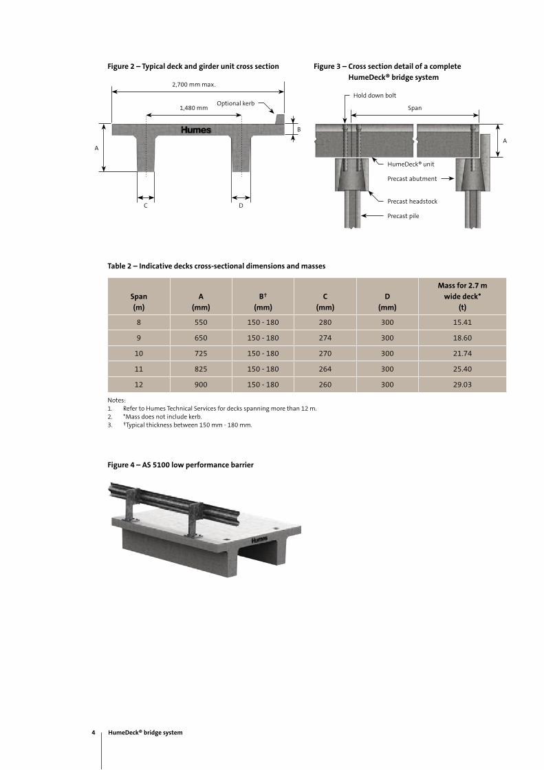
Figure 3 – Cross section detail of a complete
HumeDeck® bridge system
Figure 4 – AS 5100 low performance barrier
Figure 2 – Typical deck and girder unit cross section
Hold down bolt
HumeDeck® unit
Span
Precast abutment
Precast headstock
Precast pile
A
2,700 mm max.
Optional kerb1,480 mm
C
A
B
D
Table 2 – Indicative decks cross-sectional dimensions and masses
Span
(m)
A
(mm)
B†
(mm)
C
(mm)
D
(mm)
Mass for 2.7 m
wide deck*
(t)
8 550 150 - 180 280 300 15.41
9 650 150 - 180 274 300 18.60
10 725 150 - 180 270 300 21.74
11 825 150 - 180 264 300 25.40
12 900 150 - 180 260 300 29.03
Notes:1. Refer to Humes Technical Services for decks spanning more than 12 m.2. *Mass does not include kerb.3. †Typical thickness between 150 mm - 180 mm.
4 HumeDeck® bridge system

Table 3 – Substructure components
Piles* Two types:
• Rectangular reinforced concrete piles - measure up to 550 mm x 550 mm
wide. Piles can be potted or driven.
• Prestressed octagonal piles - measure from 400 mm to 550 mm diameter.
Both types are designed to be mechanically joined to meet designated length.
Headstock and abutments† • Can be installed on newly erected piles or existing piers.
• Custom made to fit a variety of traffic profiles and to suit a specific bridge width.
• A crossfall can be maintained in one or two directions.
Notes:* Refer to Figure 5.† Refer to Figure 6.
Figure 5 – Piles Figure 6 – Abutment
Precast pilePrecast
prestressed pile
HumeDeck® bridge system 5
Hu
meD
eck®
bri
dge
sys
tem

Safety recommendation
The precast concrete component should only be
lifted using the appropriate lifting clutches and from
the designated lifting points which are shown in the
project-specific drawings. Each deck is fitted with at least
four Swiftlift® foot anchors. All lifting equipment must be
certified to lift the specific mass and approved for lifting
heavy componentry.
The mass of the HumeDeck® units vary depending on its
geometry; weights will be clearly marked on the precast
units and in the relevant project drawings.
Handling and installation
All lifting and placement must proceed with caution
and strictly in accordance with all relevant occupational
health and safety standards. Bumping or impact
with abutments and piers can cause damage and
should be avoided.
The advice in this publication is of a general nature only.
Where any doubt exists as to the safety of a particular
lift or installation procedure, seek the guidance of a
professional engineer or contact Humes for general
advice. Humes supply a lifting diagram as part of our
standard drawings.
Safety requirements and regulations must be observed
during transportation, handling, storage and installation
of HumeDeck® units. It is the responsibility of the
contractor installing HumeDeck® units to produce a Safe
Work Method Statement that complies with relevant law,
codes of practice, standards and safety regulations.
6 HumeDeck® bridge system

Pre-delivery
To ensure the safe and efficient installation of the
HumeDeck® bridge system it is important to undertake
sufficient planning prior to its arrival on site.
Specific tasks, responsibilities and equipment
requirements are outlined in Appendix 1, Installation
check list. These items should be addressed prior to
delivery of the HumeDeck® units.
Site meeting
A site meeting can be arranged one to two weeks prior
to delivery and installation to delegate responsibilities
and discuss constraints and special considerations. It is
suggested that representatives from the main contractor
or installation contractor, the crane company, and
Humes should attend a site meeting.
Delivery
The rate of delivery should be decided by the main
contractor or installation contractor in consultation with
Humes; this will be dependent on issues including:
• on-site access
• crane size and reach
• transport availability
• site traffic control
• nominated project time.
Humes recommend the development of a shipping
plan to document the sequence, date and delivery
time of each HumeDeck® unit. This will provide
better management of transport access, carriage,
and on-site materials.
Top: Placing a deck and girder unit onto an abutment
Middle:HumeDeck® unit lifting process
Opposite page:Installed HumeDeck® system
HumeDeck® bridge system 7
Hu
meD
eck®
bri
dge
sys
tem

Lifting
All the precast units are supplied with Swiftlift® cast-in
lifting anchors to enable safe handling. To prevent stress
and possible concrete cracking, all units must be handled
using the cast-in lifting anchors and appropriately sized
lifting clutches. If the contractor does not have his own
lifting clutches they can be obtained from the crane
contractor or hired from an approved supplier. It is the
installation contractor’s responsibility to ensure the
correct sized lifting clutches are available on site.
The lifting points and size of lifting anchors are clearly
shown on Humes drawings. A minimum four point lift
is required at all times with a minimum sling angle of
60° to the horizontal (refer to Figure 8). Use a proper link
connection to ensure a four point lift.
The precast deck will be transported in a horizontal
position (refer to Figure 7). Wherever possible, all
modular components should be lifted from the delivery
truck and set directly onto the prepared substructure.
However, if temporary site storage is necessary, the deck
units can be stored on firm leveled ground on hardwood
timber bearers. A minimum number of two bearers
should be used underneath the location of the lifting
anchors (refer to Figure 9). If the ground is suitable, a
maximum of two decks may be stacked with hardwood
timber bearers in between.
Figure 7 – Deck transport
Figure 9 – Deck stacking
Figure 8 – Deck lifting
Timber bearer location
60°60°
8 HumeDeck® bridge system
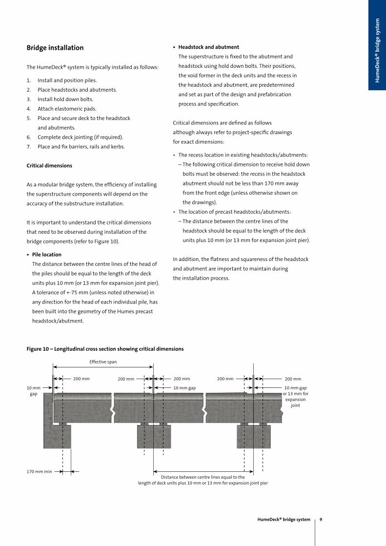
Figure 10 – Longitudinal cross section showing critical dimensions
Bridge installation
The HumeDeck® system is typically installed as follows:
1. Install and position piles.
2. Place headstocks and abutments.
3. Install hold down bolts.
4. Attach elastomeric pads.
5. Place and secure deck to the headstock
and abutments.
6. Complete deck jointing (if required).
7. Place and fix barriers, rails and kerbs.
Critical dimensions
As a modular bridge system, the efficiency of installing
the superstructure components will depend on the
accuracy of the substructure installation.
It is important to understand the critical dimensions
that need to be observed during installation of the
bridge components (refer to Figure 10).
• Pile location
The distance between the centre lines of the head of
the piles should be equal to the length of the deck
units plus 10 mm (or 13 mm for expansion joint pier).
A tolerance of +-75 mm (unless noted otherwise) in
any direction for the head of each individual pile, has
been built into the geometry of the Humes precast
headstock/abutment.
• Headstock and abutment
The superstructure is fixed to the abutment and
headstock using hold down bolts. Their positions,
the void former in the deck units and the recess in
the headstock and abutment, are predetermined
and set as part of the design and prefabrication
process and specification.
Critical dimensions are defined as follows
although always refer to project-specific drawings
for exact dimensions:
• The recess location in existing headstocks/abutments:
– The following critical dimension to receive hold down
bolts must be observed: the recess in the headstock
abutment should not be less than 170 mm away
from the front edge (unless otherwise shown on
the drawings).
• The location of precast headstocks/abutments:
– The distance between the centre lines of the
headstock should be equal to the length of the deck
units plus 10 mm (or 13 mm for expansion joint pier).
In addition, the flatness and squareness of the headstock
and abutment are important to maintain during
the installation process.
Effective span
170 mm minDistance between centre lines equal to the
length of deck units plus 10 mm or 13 mm for expansion joint pier
10 mm gap or 13 mm for
expansion joint
200 mm200 mm
10 mm gap
200 mm200 mm200 mm
10 mm gap
HumeDeck® bridge system 9
Hu
meD
eck®
bri
dge
sys
tem

Install and position piles
Pile installation is not managed by Humes. Humes is not
responsible for any cost or possible construction delay if
the head of any pile is not within tolerance. Drive or pot
the piles to the required set.
Piles are installed in the following procedure:
1. Check and approve the location of the piles by survey
prior to installing the headstock or abutment. A
tolerance of +-75 mm (unless noted otherwise) in
any direction for the head of each individual pile,
has been built into the geometry of the headstock/
abutment (refer to pile location on page 8).
2. Expose the pile head reinforcement.
3. Cut back the concrete at the pile head to a level
75 mm above the soffit of the headstock/abutment.
4. Trim the pile longitudinal reinforcement
to the projection bar length nominated on
the project drawing.
5. Fix the support steel brackets around the piles;
these brackets are temporary and are designed
to support the headstock/abutment during
installation, and should be retained in position until
penetrations in headstock/abutment have been
concreted, and concrete reaches at least two thirds
of its specified strength (refer to bracket fixing
procedure, Appendix 2).
6. Fully fasten the brackets to the specified torque, and
check the position and level of each bracket as it will
affect the level of headstocks/abutments.
7. Place formply over the steel bracket and around the
pile in order to contain the grout; this will be held in
position when placing the headstock/abutment. The
thickness of the timber former should be considered
when determining the bracket level.
8. Seal the gap between the bracket and the pile
to prevent grout leaking out during headstock/
abutment void filling.
Top:Temporary steel support brackets attached to piles
Bottom:Formply placed over steel bracket
10 HumeDeck® bridge system

Place headstocks and abutments
1. Lift the headstock/abutment into place on top of the
piles using its designated lifting points.
a) The headstock/abutments are designed to
suit the specific size and number of piles
required for the project. Penetrations through
the headstock/abutments are of a number
and size to receive the relevant pile head
+-75 mm. The penetration is smaller at the top
of the headstock/abutment.
b) Reinforcement bars act as a potential
safety barrier, running the length of the
headstock/abutment, past the penetration
and over the piles. These reinforcement bars
should not be trimmed or bent.
c) In the event of any clash between
headstock/abutment bars and pile bars, please
contact Humes Technical Services to review
the products integrity.
2. Check location and levels and use steel shims to
adjust if required.
3. Check the location, alignment and level of the
headstock/abutment before placing concrete.
4. Fix/adjust reinforcement within penetrations.
5. Place and vibrate concrete/grout in penetrations.
Refer to project specific drawings for the
concrete/grout properties.
6. After concrete has reached two thirds of its
nominated 28 day strength, remove the bracket and
temporary former (refer to project specific drawings
for concrete specifications).
7. After installation, mark the headstock and
abutments with the centre of each deck. Also mark
the ends of each deck unit to assist in aligning the
decks during installation.
Top and bottom:Placement of headstock/abutments onto piles
HumeDeck® bridge system 11
Hu
meD
eck®
bri
dge
sys
tem
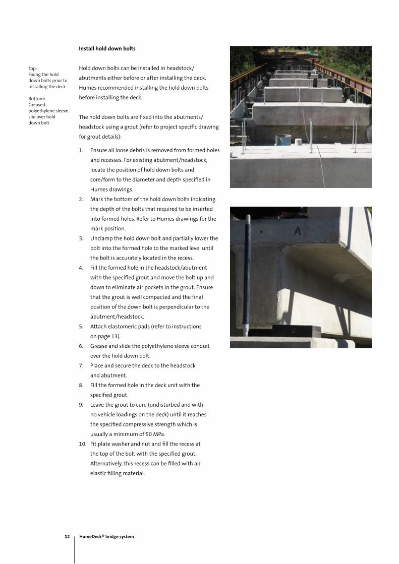
Install hold down bolts
Hold down bolts can be installed in headstock/
abutments either before or after installing the deck.
Humes recommended installing the hold down bolts
before installing the deck.
The hold down bolts are fixed into the abutments/
headstock using a grout (refer to project specific drawing
for grout details):
1. Ensure all loose debris is removed from formed holes
and recesses. For existing abutment/headstock,
locate the position of hold down bolts and
core/form to the diameter and depth specified in
Humes drawings.
2. Mark the bottom of the hold down bolts indicating
the depth of the bolts that required to be inserted
into formed holes. Refer to Humes drawings for the
mark position.
3. Unclamp the hold down bolt and partially lower the
bolt into the formed hole to the marked level until
the bolt is accurately located in the recess.
4. Fill the formed hole in the headstock/abutment
with the specified grout and move the bolt up and
down to eliminate air pockets in the grout. Ensure
that the grout is well compacted and the final
position of the down bolt is perpendicular to the
abutment/headstock.
5. Attach elastomeric pads (refer to instructions
on page 13).
6. Grease and slide the polyethylene sleeve conduit
over the hold down bolt.
7. Place and secure the deck to the headstock
and abutment.
8. Fill the formed hole in the deck unit with the
specified grout.
9. Leave the grout to cure (undisturbed and with
no vehicle loadings on the deck) until it reaches
the specified compressive strength which is
usually a minimum of 50 MPa.
10. Fit plate washer and nut and fill the recess at
the top of the bolt with the specified grout.
Alternatively, this recess can be filled with an
elastic filling material.
Top:Fixing the hold down bolts prior to installing the deck
Bottom:Greased polyethylene sleeveslid over hold down bolt
12 HumeDeck® bridge system
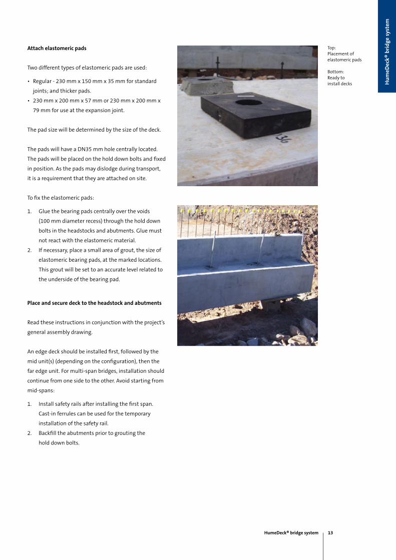
Attach elastomeric pads
Two different types of elastomeric pads are used:
• Regular - 230 mm x 150 mm x 35 mm for standard
joints; and thicker pads.
• 230 mm x 200 mm x 57 mm or 230 mm x 200 mm x
79 mm for use at the expansion joint.
The pad size will be determined by the size of the deck.
The pads will have a DN35 mm hole centrally located.
The pads will be placed on the hold down bolts and fixed
in position. As the pads may dislodge during transport,
it is a requirement that they are attached on site.
To fix the elastomeric pads:
1. Glue the bearing pads centrally over the voids
(100 mm diameter recess) through the hold down
bolts in the headstocks and abutments. Glue must
not react with the elastomeric material.
2. If necessary, place a small area of grout, the size of
elastomeric bearing pads, at the marked locations.
This grout will be set to an accurate level related to
the underside of the bearing pad.
Place and secure deck to the headstock and abutments
Read these instructions in conjunction with the project’s
general assembly drawing.
An edge deck should be installed first, followed by the
mid unit(s) (depending on the configuration), then the
far edge unit. For multi-span bridges, installation should
continue from one side to the other. Avoid starting from
mid-spans:
1. Install safety rails after installing the first span.
Cast-in ferrules can be used for the temporary
installation of the safety rail.
2. Backfill the abutments prior to grouting the
hold down bolts.
Top:Placement of elastomeric pads
Bottom:Ready to install decks
HumeDeck® bridge system 13
Hu
meD
eck®
bri
dge
sys
tem

Complete deck jointing (if required)
A longitudinal joint is formed where multiple units are
placed adjacent to each other to provide the required
carriageway width. The longitudinal joint may be a butt
joint or an in-situ joint.
• Butt joint:
This is the most common deck joint due to its ease
of installation. This joint type has a nominal 10 mm
gap between units which may be either sealed with
a flexible sealant, or left open. Humes recommend
sealing the joints to keep out solid objects like stone.
The sealing process will prevent spalling of the
concrete surface.
• In-situ joint:
The in-situ joint is a reinforced concrete joint poured
on site, after deck units have been placed. The joint
provides a continuous concrete running surface across
the width of the bridge and may be constructed using
various methods.
Figure 11 – In-situ joint detail
Figure 12 – Plywood formwork for in-situ jointing
The following method is recommended by Humes
however specific work instructions remain the client’s
and/or contractor’s responsibility:
1. Place 20 mm thick plywood formwork to the
underside of the joint location (refer to Figure 11).
Plywood formwork can be avoided for webs 180 mm
or thicker. A recess in the deck flange can be
designed to form the in-situ joint.
2. Place timber or steel beams laterally across the joint.
3. Bolt the timber through the joint to the underside of
the formwork beams (refer to Figure 12).
4. Fit the supplied longitudinal steel reinforcement as
shown on the project drawings.
5. Clean all surfaces within the joint.
6. Prime the edge of the HumeDeck® units with a
suitable bonding agent (AV 600M or equivalent).
7. Cast with 50 MPa concrete (or as specified on the
project drawings) with a maximum aggregate size
of 14 mm. The concrete must be well compacted
(vibrated) and cured in an appropriate manner to
achieve the specified strength. No traffic should
traverse the completed bridge until the in-situ
concrete has reached the specified strength.
Top:Longtiudunal joint being formed
14 HumeDeck® bridge system

Place and fix barriers, rails and kerbs
Concrete barrier fixing
1. Align the ribbed tubing with the cast-in starter
bars and slowly drop the barrier over the starter
bars (if required use a 10-20 mm thick mortar bed to
ensure barriers are level), refer to Figure 13 and 14.
2. Once barriers have been located into place fill the
ribbed tubing (from the top of the barrier) with
50 MPa grout.
3. Recheck the level of the grout and refill if required.
Figure 13 – Concrete barrier fixing
Figure 14 – Concrete barrier fixing cross section
Jersey kerb
Ø42 mm internal ribbed tubing at 225 CRS (galv).
Cast-in bar grout fill after installation
Top and bottom:Fixing concrete barrier onto deck
HumeDeck® bridge system 15
Hu
meD
eck®
bri
dge
sys
tem

Rail barrier fixing
If ordered, HumeDeck® units are supplied with the
appropriate steel brackets, ferrules and holes for hold
down bolts required for fixing non-concrete barriers.
Cross section details of these fixing arrangements are
shown in Figures 15-19. Refer to barrier supplier and the
road authority standards for fixing details.
Figure 18 – Regular performance barrier fixing
cross section
150
180
320 min
Sleeves
Plan
Cast-in bolts
105
105
Barrier posts and base plates by others
Figure 16 – Low and regular performance barrier fixing
Figure 15 – Austroads level 3 barrier fixing
Figure 17 – Low performance barrier fixing cross section
Figure 19 – Austroads level 3 barrier fixing cross section
90
100
Plan
Cast-in M20 x 70 elephants foot
ferrules
15070
150 x 150 EA by others
150
150
160
105
105
Barrier posts and base plates by others
Cast-in bolts
Plan
Sleeves
16 HumeDeck® bridge system

Figure 20 – Kerb fixing into deck
150
85
150
20
150 high precast bolt on concrete kerb
Ø30 Hole for M20 galv bolt x 300 LG
Kerb fixing
Wide kerbs (150 mm) can be cast integrally with the deck
units or as separate precast units and bolted to the deck
units on site (refer to Figure 20 below).
HumeDeck® bridge system 17
Hu
meD
eck®
bri
dge
sys
tem

Project....................................................................................
Client......................................................................................
Location..................................................................................
Modular components Number of units Approximate mass
Deck units with kerb
Deck units without kerb
Traffic barriers
Precast kerbs
Abutment
Headstock
Rectangular piles
Hexagonal piles
Sup
er s
tru
ctu
reSu
b s
tru
ctu
re
Appendix 1 – HumeDeck® bridge system installation check list
Requirement Action
Ensure site access is suitable for trucks and cranes. Customer
Organise HumeDeck® units to be delivered to site in sequence and
quantities to suit erection.
Customer/Humes
Have hardwood timber bearers available for stacking of precast units. Customer/Crane company
Organise Swiftlift® lifting knuckles and appropriate lifting equipment
including running snatch blocks for:
Product Length (m)
Unloading and installing the decks.
Unloading and installing the abutment and headstock.
Unloading and installing the precast piles.
Approved lifting knuckles required:
Size (capacity) Number required
10 tonne
20 tonne
Crane company
Check all component unit lifting points with lifting knuckles before
units leave factory.
Humes
Site
pre
par
atio
n a
nd
del
iver
yLi
ftin
g eq
uip
men
t
18 HumeDeck® bridge system
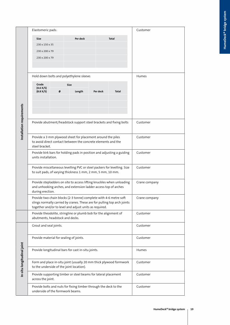
Elastomeric pads:
Size Per deck Total
230 x 150 x 35
230 x 200 x 79
230 x 200 x 79
Customer
Hold down bolts and polyethylene sleeve:
Grade(4.6 X/S)(8.8 X/S)
Size
Per deck Totalø Length
Humes
Provide abutment/headstock support steel brackets and fixing bolts Customer
Provide a 3 mm plywood sheet for placement around the piles
to avoid direct contact between the concrete elements and the
steel bracket.
Customer
Provide birk bars for holding pads in position and adjusting a guiding
units installation.
Customer
Provide miscellaneous levelling PVC or steel packers for levelling. Size
to suit pads, of varying thickness 1 mm, 2 mm, 5 mm, 10 mm.
Customer
Provide stepladders on site to access lifting knuckles when unloading
and unhooking arches, and extension ladder access top of arches
during erection.
Crane company
Provide two chain blocks (2-3 tonne) complete with 4-6 metre soft
slings normally carried by cranes. These are for pulling top arch joints
together and/or to level and adjust units as required.
Crane company
Provide theodolite, stringline or plumb bob for the alignment of
abutments, headstock and decks.
Customer
Grout and seal joints. Customer
Provide material for sealing of joints. Customer
Provide longitudinal bars for cast in-situ joints. Humes
Form and place in-situ joint (usually 20 mm thick plywood formwork
to the underside of the joint location).
Customer
Provide supporting timber or steel beams for lateral placement
across the joint.
Customer
Provide bolts and nuts for fixing timber through the deck to the
underside of the formwork beams.
Customer
Inst
alla
tion
req
uir
emen
tsIn
-sit
u lo
ngi
tud
inal
join
t
HumeDeck® bridge system 19
Hu
meD
eck®
bri
dge
sys
tem
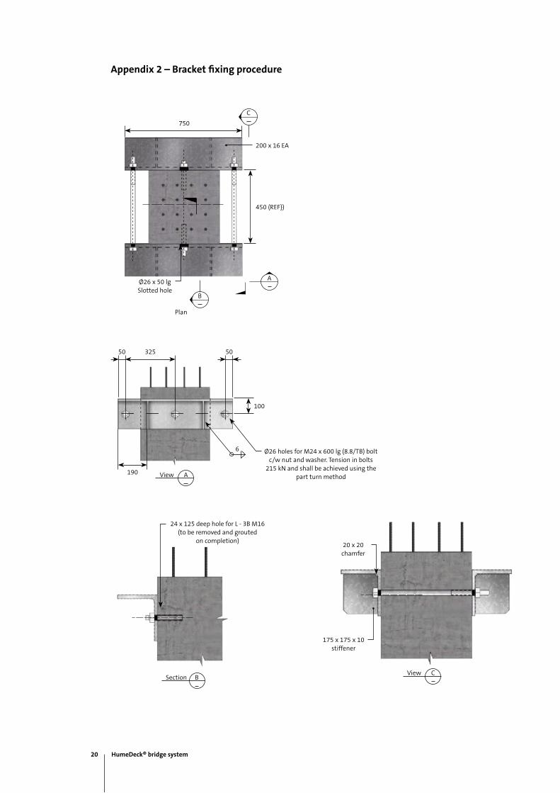
Appendix 2 – Bracket fixing procedure
PLAN
A
750
PLAN
C
450 (REF})
200 x 16 EA
PLAN
Ø26 x 50 lgSlotted hole
PLAN
B
Plan
175 x 175 x 10 stiffener
20 x 20chamfer
CViewBSection
24 x 125 deep hole for L - 3B M16(to be removed and grouted
on completion)
32550 50
100
190 AView
Ø26 holes for M24 x 600 lg (8.8/TB) bolt c/w nut and washer. Tension in bolts
215 kN and shall be achieved using the part turn method
6
20 HumeDeck® bridge system

National sales 1300 361 601
humes.com.au
Contact information
Melbourne
Ph: (03) 9360 3888
Fax: (03) 9360 3887
Tasmania
Launceston
Ph: (03) 6335 6300
Fax: (03) 6335 6330
South Australia
Adelaide
Ph: (08) 8168 4544
Fax: (08) 8168 4549
Western Australia
Gnangara
Ph: (08) 9302 8000
Fax: (08) 9309 1625
Perth
Ph: (08) 9351 6999
Fax: (08) 9351 6977
Northern Territory
Darwin
Ph: (08) 8984 1600
Fax: (08) 8984 1614
Head Office
18 Little Cribb St
Milton 4064 QLD
Ph: (07) 3364 2800
Fax: (07) 3364 2963
Queensland
Brisbane/Gold Coast
Ph: (07) 3866 7100
Fax: (07) 3866 7101
Bundaberg
Ph: (07) 4152 2644
Fax: (07) 4152 5847
Rockhampton
Ph: (07) 4924 7900
Fax: (07) 4924 7901
Sunshine Coast
Ph: (07) 5472 9700
Fax: (07) 5472 9711
Toowoomba
Ph: (07) 4694 1420
Fax: (07) 4634 3874
Townsville
Ph: (07) 4758 6000
Fax: (07) 4758 6001
New South Wales
Canberra
Ph: (02) 6285 5309
Fax: (02) 6285 5334
Grafton
Ph: (02) 6644 7666
Fax: (02) 6644 7313
Kempsey
Ph: (02) 6562 6755
Fax: (02) 6562 4235
Lismore
Ph: (02) 6621 3684
Fax: (02) 6622 1342
Newcastle
Ph: (02) 4032 6800
Fax: (02) 4032 6822
Sydney
Ph: (02) 9832 5555
Fax: (02) 9625 5200
Tamworth
Ph: (02) 6763 7300
Fax: (02) 6763 7301
Victoria
Echuca
Ph: (03) 5480 2371
Fax: (03) 5482 3090

National sales 1300 361 601
humes.com.au
This brochure supersedes all previous literature on this subject. As the specifications and details contained in this publication may change please check with Humes Customer Service for confirmation of current issue. This document is provided for information only. Users are advised to make their own determination as to the suitability of this information for their own specific circumstances. We accept no responsibility for any loss or damage resulting from any person acting on this information. Humes is a registered trademark and a registered business name of Holcim (Australia) Pty Ltd. HumeDeck is a registered trademark of Holcim (Australia) Pty Ltd. Swiftlift is a registered trademark of ITW ConstructionProducts Australia Pty Ltd © September 2012 Holcim (Australia) Pty Ltd ABN 87 099 732 297
A Division on Holcim Australia