Embed Size (px)
Citation preview
REPORT OF INVESTIGATIONS/1994
PLEASE 00 Nor REMOVE FRavI LIBRARY
Design Methods To Enhance the Capacity, Stiffness, and Timber Utilization of Wood Cribs
r UBRARY f SPOKANE RESEAriCH CENTER
RECEIVED
By Thomas M. Barczak and David F. Gearhart MAR 1 b J94
us BURE.t.U Of f"llNES E. 315 t.fJ+./TOOMEAY AVE.
UNITED STATES DEPARTMENT OF THE INTERIOR u "-~.
U.S. Department of the Interior Mission Statement
As the Nation's principal conservation agency, the Department of the Interior has responsibility for most of our nationally-owned public lands and natural resources. This includes fostering sound use of our land and water resources; protecting our fish, wildlife, and biological diversity; preserving the environmental and cultural values of our national parks and historical places; and providing for the enjoyment of life through outdoor recreation. The Department assesses our energy and mineral resources and works to ensure that their development is in the best interests of all our people by encouraging stewardship and citizen participation in their care. The Department also has a major responsibility for American Indian reservation communities and for people who live in island territories under U.S. administration.
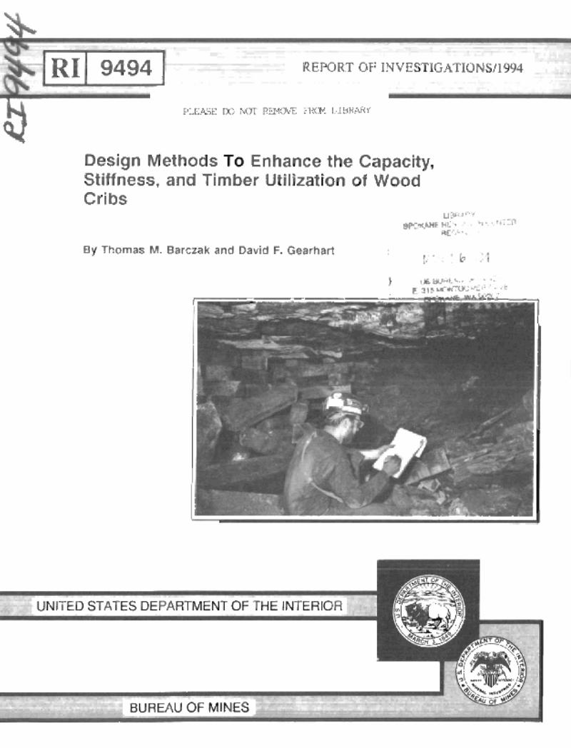
Cover Photograph:' Inspection of roof fall in cribbed mine entry by U.S. Bureau of Mines engineer. Photo by Frank Chase, Pittsburgh Research Center, U.S. Bureau of Mines, Pittsburgh, PA.
Report of Investigations 9494
Design Methods To Enhance the Capacity, Stiffness, and Timber Utilization of Wood Cribs
By Thomas M. Barczak and David F. Gearhart
UNITED STATES DEPARTMENT OF THE INTERIOR Bruce Babbitt, Secretary
BUREAU OF MINES , I, , I I, , I , , ! \.

I
"
,I 'I [,
International Standard Serial Number ISSN 1066-5552
f ,
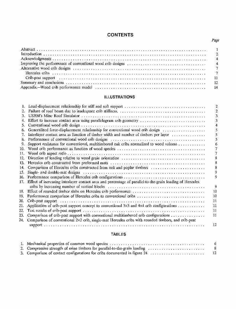
CONTENTS Page
(.';
Abstract. . . . . . . . . . . . . . . . . . . . . . . . . . . . . . . . . . . . . . . . . . . . . . . . . . . . . . . . . . . . . . . . . . . . . . . . . . . 1 Introduction . . . . . . . . . . . . . . . . . . . . . . . . . . . . . . . . . . . . . . . . . . . . . . . . . . . . . . . . . . . . . . . . . . . . . . . . 2 Acknowledgments . . . . . . . . . . . . . . . . . . . . . . . . . . . . . . . . . . . . . . . . . . . . . . . . . . . . . . . . . . . . . . . . . . . . 4 Improving the performance of conventional wood crib designs ................................... 4 Alternative wood crib designs ........................................................... 7
Hercules cribs ..................................................................... 7 Crib-post support ......................................... ,....................... 11
Summary and conclusions . . . . . . . . . . . . . . . . . . . . . . . . . . . . . . . . . . . . . . . . . . . . . . . . . . . . . . . . . . . . . . 12 Appendix.-Wood crib performance model ................................................. 14
ILLUSTRATIONS
1. Load-displacement relationship for stiff and soft support . . . . . . . . . . . . . . . . . . . . . . . . . . . . . . . . . . . . 2 2. Failure of roof beam due to inadequate crib stiffness. ... . . . . . . . . . . . . . . . . . . . . . . . . . . . . . . . . . . . 2 3. USBM's Mine Roof Simulator . . . . . . . . . . . . . . . . . . . . . . . . . . . . . . . . . . . . . . . . . . . . . . . . . . . . . . . 3 4. Effort to increase contact area using parallelogram crib geometry . . . . . . . . . . . . . . . . . . . . . . . . . . . . . 3 5. Conventional wood crib design . . . . . . . . . . . . . . . . . . . . . . . . . . . . . . . . . . . . . . . . . . . . . . . . . . . . . . . 4 6. Generalized force-displacement relationship for conventional wood crib design ................... 5 7. Interlayer contact area as function of timber width and number of timbers per layer ............... 5 8. Performance of conventional wood crib designs .......................................... 5 9. Support resistance for conventional, multi timbered oak cribs normalized to wood volume. . . . . . . . . . . . 6
10. Wood crib performance as function of wood species . . . . . . . . . . . . . . . . . . . . . . . . . . . . . . . . . . . . . . . 7 11. Wood crib aspect ratio .. : . . . . . . . . . . . . . . . . . . . . . . . . . . . . . . . . . . . . . . . . . . . . . . . . . . . . . . . . . . 7 12. Direction of loading relative to wood grain orientation ..................................... 8 13. Hercules crib constructed from preformed mats .......................................... 8 14. Comparison of Hercules cribs constructed from oak and poplar timbers ........................ 8 15. Single- and double-mat designs ...................................................... 9 16. Performance comparison of Hercules crib configurations. . . . . . . . . . . . . . . . . . . . . . . . . . . . . . . . . . . . 9 17. Effect of increasing interlayer contact area and percentage of parallel-to-the-grain loading of Hercules
cribs by increasing number of vertical blocks ........................................... 9 18. Effect of rounded timber slabs on Hercules crib performance ....................... '. . . . . . . . . 10 19. Performance comparison of Hercules cribs to conventional cribs .. . . . . . . . . . . . . . . . . . . . . . .. . . . . . 10 20. Crib-post support ................................................................ 11 21. Application of crib-post support concept to conventional 3x3 and 4x4 crib configurations . . . . . . . . . . . . 11 22. Test results of crib-post support . . . . . . . . . . . . . . . . . . . . . . . . . . . . . . . . . . . . . . . . . . . . . . . . . . . . . . 11 23. Comparison of crib-post support with conventional multitimbered crib configurations. . . . . . . . . . . . . . . 11 24. Comparison of conventional 2x2 crib, single-mat Hercules cribs with rounded timbers, and crib-post
support. . . . . . . . . . . . . . . . . . . . . . . . . . . . . . . . . . . . . . . . . . . . . . . . . . . . . . . . . . . . . . . . . . . . . . . 12
TABLES
1. Mechanical properties of common wood species . . . . . . . . . . . . . . . . . . . . . . . . . . . . . . . . . . . . . . . . . . 6 2. Compressive strength of mine timbers for parallel-to-the-grain loading ......................... 8 3. Comparison of contact configurations for cribs documented in figure 24 ....................... .12

I ~ UNIT OF MEASURE ABBREVIATIONS USED IN THIS REPORT
cm centimeter kN/m kilonewtol1 per meter
cm2 square centimeter kPa kilopascal
cm/cm centimeter per centimeter Ib pound
ft foot Ib/in3 pound per cubic inch
in inch MN meganewton
in2 square inch N newton
kip 1,000 pounds N/cm3 newton per cubic centimeter
kip/in 1,000 pounds per inch pct percent
kN kilonewton psi pound per square inch
h
I' , i
DESIGN METHODS TO ENHANCE THE CAPACITY, STIFFNESS, AND TIMBER UTILIZATION OF WOOD CRIBS
By Thomas M. Barczak 1 and David F. Gearhart2
ABSTRACT
This U.S. Bureau of Mines report describes methods to enhance the capacity, stiffness, and timber utilization of wood crib supports. Since stiffer supports minimize strata deflections that contribute to roof instability, efforts to maximize crib stiffness while maintaining stability through a wide displacement range should be a design priority. The stiffness and capacity of conventional crib. designs, employing alternating layers of wood timbers that are loaded perpendicular to the grain, can be increased by increasing the interlayer contact area or by using higher strength wood. Contact area can be increased by using wider timbers or employing more timbers per layer. Concepts that provide parallel-to-the-grain timber loading will provide substantial increases in crib stiffness and capacity. Two concepts that utilize this principle are examined: (1) an original South African design that constructs wood cribs from preformed layers (mats) of timber where short blocks are oriented vertically between horizontal slabs; and (2) a design that employs full lengths of timber placed vertically in the interior of a conventional crib structure. These designs also provide more efficient timber utilization by providing greater support capacity per volume of wood used in the crib construction.
iResearch physicist, U.S. Bureau of Mines, Pittsburgh Research Center, Pittsburgh, PA. 2Pl'Oject engineer, SSI Selvices Inc., Pittsburgh, PA.
2
INTRODUCTION
Wood cribs are used extensively to stabilize underground mine openings. This is accomplished by providing resistance to deflections of the immediate roof and floor and by supporting the weight of rock masses in the immediate roof that become detached from stable roof structures. Wood cribs maintain stability and provide a resistive force through a large displacement range, making them compatible with a wide variety of mining conditions.
The purpose of this U.S. Bureau of Mines (USBM) investigation is to identify methods to increase the capacity and stiffness of wood cribs, and to improve the utilization of wood in the crib construction while maintaining the necessary stability of the crib structure. These objectives meet the USBM's goals of improving ground support technology to reduce hazards and the cost of mining.
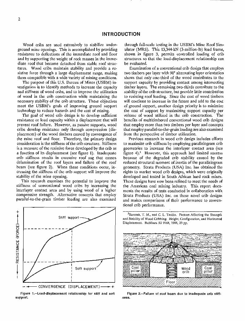
The goal of wood crib design is to develop sufficient resistance or load capacity within a displacement that will prevent roof failure. However, as passive supports, wood cribs develop resistance only through com pression (displacement) of the wood timbers caused by convergence of the mine roof and floor. Therefore, the primary design consideration is the stiffness of the crib structure. Stiffness is a measure of the resistive force developed by the crib as a function of its displacement (see figure 1). Inadequate crib stiffness results in excessive roof sag that causes delamination of the roof layers and failure of the roof beam' (see figure 2). When these conditions occur, increasing the stiffness of the crib support will improve the stability of the mine opening.
This research examines the potential to improve the stiffness of conventional wood cribs by increasing the interlayer contact area and by using wood of a higher compressive strength. Alternative concepts that employ parallel-to-the-grain timber loading are also examined
+
t ..... w U 0:::
f2 w u z f':! (/)
u; W 0:::
!
Stiff support
Soft support
- - CONVERGENCE (OISPLACEMENT)- + Figure 1.-Load-displacement relationship for stiff and soft
support.
through full-scale testing in the USBM's Mine Roof Simulator (MRS). This 13,344-kN (3-million-Ib) load frame, shown in figure 3, permits controlled loading of crib structures so that the load-displacement relationship can be evaluated.
Examination of a conventional crib design that employs two timbers per layer with 900 alternating layer orientation shows that only one-third of the wood contributes to the support capacity by providing contact among intersecting timber layers. The remaining two-thirds contribute to the stability of the crib structure, but provide little contribution to resisting roof loading. Since the cost of wood timbers will continue to increase in the future and add to the cost of ground support, another design priority is to minimize the cost of support by maximizing support capacity per volume of wood utilized in the crib construction. The benefits of multitimbered conventional wood crib designs that employ more than two timbers per layer and concepts that employ parallel-to-the-grain loading are also examined from the perspective of timber utilization.
Previous research in wood crib design includes efforts to maximize crib stiffness by employing parallelogram crib geometries to increase the interlayer contact area (see figure 4).3 However, this approach had limited success because of the degraded crib stability caused by the reduced structural moment of inertia of the parallelogram geometry. Strata Products (USA) Inc. has obtained the rights to market wood crib designs, which were originally developed and tested in South African hard rock mines. These designs have now been refined to meet the needs of the American coal mining industry. This report documents the results of tests conducted in collaboration with Strata Products (USA) Inc. on these novel crib designs and makes comparisons of their performance to conventional crib performance.
3Barczak, T. M., and C. L. Tasillo. Factors Affecting the Strength and Stability of Wood Cribbing: Height, Configuration, and Horizontal Displacement. BuMines RI 9168, 1988, 23 pp .
Figure 2.-Failure of roof beam due to inadequate crib stiffness.
·l· . , i
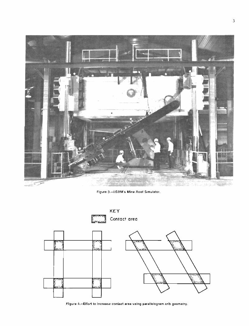
Figure 3.-USBM's Mine Roof Simulator.
£:J .. '. . . . -~
KEY
Contact area
Fiigure 4.-Effort to Increase contact area using parallelogram crib geometry.
3

4
ACKNOWLEDGMENTS
The authors wish to acknowledge Martin Van Der Merwe, vice president of marketing, and Cliff McCartney, field engineer, of Strata Products (USA) Inc., Atlanta, GA. Mr. Van Der Merwe was responsible for promoting a Memorandum of Agreement with the USBM for designing the Hercules crib to accommodate American wood species and mining conditions. This objective was accomplished through full-scale testing of several Hercules crib designs in the USBM's MRS. Gratitude is also expressed to
Frans Pienaar, research consultant to Strata Products (USA) Inc., for reviewing the USBM's wood crib performance model and participating in the testing of the Hercules cribs at the USBM facility. Finally, our appreciation is extended to Brian Mueller, project engineer, SSI Services Inc., Pittsburgh, PA, for assisting in conducting tests and providing input to the research program and preparation of this report.
IMPROVING THE PERFORMANCE OF CONVENTIONAL WOOD CRIB DESIGNS
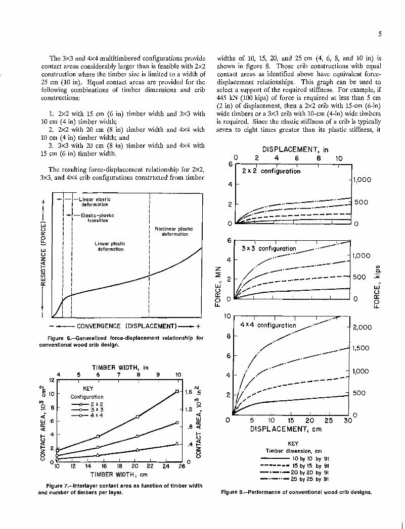
Wood cribs are typically constructed in an open box configuration by stacking layers of timber in opposite direction as shown in figure 5. The wood timbers are loaded perpendicular to the grain, producing a forcedisplacement response as illustrated in figure 6.4 The curve is largely bilinear. The initial stiffness of the crib represents the elastic behavior of the wood. After yielding, the crib stiffness is reduced as the wood exhibits plastic behavior.
The capacity and stiffness of the open box configuration is mostly determined by the contact area among intersecting crib timbers.s Therefore, the capacity and stiffness can be increased by increasing the contact area through the use of wider timbers or by increasing the number of
4Barczak, T. M., and C. L. Tasillo. Evaluation of Multitimbered Wood Crib Supports. BuMines RI 9341, 1991, 11 pp.
5Barczak, T. M., and D. F. Gearhart. Engineering Methods for the Design and Employment of Wood Cribs. BuMines IC 9361,1993,34 pp .
. .... .. . " .
. ' :.' ..... , •••• , • 1'< "j
.: ".,,' "!o'
.0',""'" 0',,' '" \'
timbers per layer in the crib construction. The designations 2x2, 3x3, and 4x4 are used to describe two-, three-, and four-timbers-per-Iayer construction designs as shown in figure 5.
The increase in contact area due to an increase in timber width and an increase in the number of timbers per layer is shown in figure 7. The contact area increases with the square of the timber width and the square of the number of timbers per layer as described in equation 1.
AREA = (TW)2 x (TIMB)2, (1)
where AREA interlayer contact area,
TW timber width,
and TIMB number of timbers per layer.
2)(2 configuration
3X3 configuration
4)(4 configuration
Figure 5.-Conventional wood crib design.
__ -------~------ __ ___ • __ r ____ , __ ~_~ •• ~.
'i
jl
The 3x3 and 4x4 multitimbered configurations provide contact areas considerably larger than is feasible with 2x2 construction where the timber size is limited to a width of 25 cm (10 in). Equal contact areas are provided for the following combinations of timber dimensions and crib constructions:
1. 2x2 with 15 cm (6 in) timber width and 3x3 with 10 cm (4 in) timber width;
2. 2x2 with 20 cm (8 in) timber width and 4x4 with 10 cm (4 in) timber width; and
3. 3x3 with 20cm (8 in) timber width and 4x4 with 15 cm (6 in) timber width.
The resulting force-displacement relationship for 2X2, 3x3, and 4x4 crib configurations constructed from timber
+
t ..... W (,) 0::
f! ..... w (,)
Z
~ C/)
f3 0::
I
-I-I-Llnear elastic I deformation I
_I-Elastic-plastic transition
LI near plastic deformation
Nonlinear plastic deformation
- - CONVERGENCE (DISPLACEMENT)-+
Figure 6.-Generallzed force-displacement relationship for conventional wood crib design.
4 12
(\J
~ 10 If)
0 8 "':'
< w 6 0:: < t; 4
~ 2 z 0 (,)
0'0
TIMBER WIDTH, in 5 6 7 8 9
KEY Configuration --0-- 2 x 2 --o-3x3 -o-4x4
10
(\J
1.6 .S If) o
1.2 ~ q; W 0::
.8 q;
t; .4~
8 12 14 16 18 20 22 24 26 0
TIMBER WIDTH, em
Figure 7.-lnterlayer contact area as function of timber width and number of timbers per layer.
5
widths of 10, 15, 20, and 25 cm (4, 6, 8, and 10 in) is shown in figure 8. Those crib constructions with equal contact areas as identified above have equivalent forcedisplacement relationships. This graph can be used to select a support of the required stiffness. For example, if 445 kN (100 kips) of force is required at less than 5 cm (2 in) of displacement, then a 2x2 crib with 15-cm (6-in) wide timbers or a 3x3 crib with lO-cm (4-in) wide timbers is required. Since the elastic stiffness of a crib is typically seven to eight times greater than its plastic stiffness, it
DISPLACEMENT, in o 2 4 6 8 10
6r---.----r--~----~--~J--~ 2 x 2 configuration
4
- "-"-2 ~ .. -" ..,..,-"- -'-'-'-/...:. .. ..-.-:..._--------
1,000
500
.I~---- ... ---o 0
6r---,----r--~----~--~~
3 x 3 conflguration __ "----.. /.. _.-. 1,000 4
z /., __ .-.-. ~ 2 .~."".-, _-------- 500
uS /~ ....... _ .... _---------------1 U It _ ~O-=:;;;-..I.---....I--....l----L..--..J..----IO l.i...
10r---.----.---.---.---~_,
4 X4 configuration,.........-.;---·· 2,000 8
1,500 .. /"
.,/ --.--. / --' ..,..-.
.. /'
6
4 1,000
500 //. ....------ ..----------
2 tI: ; ................... '. / .-------:---1 .,
o 5 10 15 20 25 DISPLACEMENT, em
KEY Timber dimension, em
10 by 10 by 91 ------- 15 by 15 by 91 -'-'-20 by 20 by 91 _ .. - .. - 25 by 25 by 91
o 30
Figure a.-Performance of conventional wood crib designs.
~
UJ (,) a:: o l.i...
6
is advantageous to design a crib to provide the required support resistance during elastic behavior (see figure 6). For example, if 890 kN (200 kips) of resistance is required, a 2x2 crib constructed with IS-cm (6-in) wide timbers will have to displace approximately 18 cm (7 in) to provide this support,. while a 3x3 crib constructed from IS-cm (6-in) wide timbers will require less than 3 cm (1 in) of displacement.
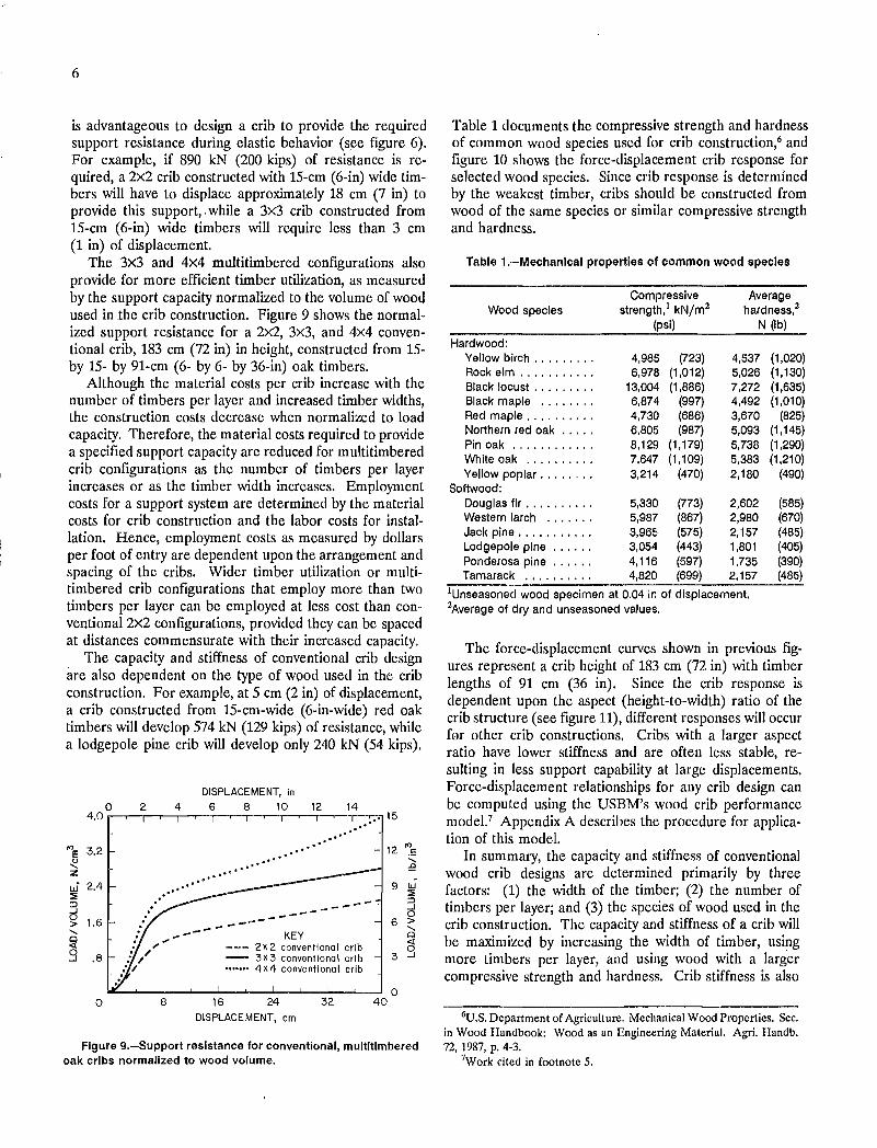
The 3x3 and 4x4 multitimbered configurations also provide for more efficient timber utilization, as measured by the support capacity normalized to the volume of wood used in the crib construction. Figure 9 shows the normalized support resistance for a 2x2, 3x3, and 4x4 conventional crib, 183 cm (72 in) in height, constructed from 15-by 15- by 91-cm (6- by 6- by 36-in) oak timbers.
Although the material costs per crib increase with the number of timbers per layer and increased timber widths, the construction costs decrease when normalized to load capacity. Therefore, the material costs required to provide a specified support capacity are reduced for multitimbered crib configurations as the number of timbers per layer increases or as the timber width increases. Employment costs for a support system are determined by the material costs for crib construction and the labor costs for installation. Hence, employment costs as measured by dollars per foot of entry are dependent upon the arrangement and spacing of the cribs. Wider timber utilization or multitimbered crib configurations that employ more than two timbers per layer can be employed at less cost than conventional 2x2 configurations, provided they can be spaced at distances commensurate with their increased capacity,
The capacity and stiffness of conventional crib design are also dependent on the type of wood used in the crib construction. For example, at 5 cm (2 in) of displacement, a crib constructed from IS-cm-wide (6-in-wide) red oak timbers will develop 574 kN (129 kips) of resistance, while a lodgepole pine crib will develop only 240 kN (54 kips).
DISPLACEMENT, in o 2 4 6 8 10 12 14
4.0 .--....-,---r-,.-....-,--r--;---.-,--r-..,--..---r-r:.". 15 ,.' .,'
""e 3.2 ~ z LJ' 2.4 ::li!
>d 1.6 "-
O...J~ .8
o
. . " ......
8
.. ' .. ' .,' .. '
•• (I ••••• .. -.....
------------- KEY --- 2x2 conventional crib - 3x3 conventional crib ....... 4x4 conventional crib
16 24 32
DISPLACEMENT, cm
9 W ::li! :3 o
6 > "Cl
C\ 3 ...J
o 40
Figure g.-Support resistance for conventional, multitimbered oak cribs normalized to wood volume.
Table 1 documents the compressive strength and hardness of common wood species used for crib construction,6 and figure 10 shows the force-displacement crib response for selected wood species. Since crib response is determined by the weakest timber, cribs should be constructed from wood of the same species or similar compressive strength and hardness.
Table 1.-Mechanlcal properties of common wood species
Compressive Average Wood species strength,! kN/m2 hardness,2
(psi) N (Ib)
Hardwood: Yellow birch ....... , . 4,9(35 (723) 4,537 (1,020) Rock eim .... , ...... 6,978 (1,012) 5,026 (1,130) Black locust ......... 13,004 (1,886) 7,272 (1,635) Black maple ..... , .. 6,874 (997) 4,492 (1,010) Red maple ......... , 4,730 (686) 3,670 (825) Northern red oak ..... 6,805 (987) 5,093 (1,145) Pin oak ., ... , ...... 8,129 (1,179) 5,738 (1,290) White oak .......... 7,647 (1,109) 5,383 (1,210) Yellow poplar ..... , .. 3,214 (470) 2,180 (490)
Softwood: Douglas fir ....•..... 5,330 (773) 2,602 (585) Western larch .... '" 5,987 (867) 2,980 (670) Jacl< pine ......... , . 3,965 (575) 2,157 (485) Lodgepole pine ...... 3,054 (443) 1,801 (405) Ponderosa pine ...... 4,116 (597) 1,735 (390) Tamarack .......... 4,820 (699) 2,157 (485)
!Unseasoned wood specimen at 0.04 In of displacement. 2Average of dry and unseasoned values.
The force-displacement curves shown in previous figures represent a crib height of 183 cm (72 in) with timber lengths of 91 cm (36 in). Since the crib response is dependent upon the aspect (height-to-width) ratio of the crib structure (see figure 11), different responses will occur for other crib constructions. Cribs with a larger aspect ratio have lower stiffness and are often less stable, resulting in less support capability at large displacements. Force-displacement relationships for any crib design can be computed using the USBM's wood crib performance model,7 Appendix A describes the procedure for application of this model.
In summary, the capacity and stiffness of conventional wood crib designs are determined primarily by three factors: (1) the width of the timber; (2) the number of timbers per layer; and (3) the species of wood used in the crib construction. The capacity and stiffness of a crib will be maximized by increasing the width of timber, using more timbers per layer, and using wood with a larger compressive strength and hardness. Crib stiffness is also
6U.S. Department of Agriculture. Mechanical Wood Properties. Sec. in Wood Handbook: Wood as an Engineering Material. Agri. Handb. 72, 1987, p. 4-3.
7Work cited in footnote 5.

DISPLACEMENT, in o 2 4 6 8 10
1. 2 r--r--r---.---,.-.--.,....-...,.-.-,-......... ---,----,
1.0
Z .8 ::1!
W .6 u 0:: f2 .4
.2
o
------...,..~ .--' ..- ...... ---- .---.--
....... --;::...... ---- .---....... _. //,'
250
200
150
100 , /y.-=::.~.:.,~:.:~:::::::::::.=:::: ....... . '///':: ....... 50
~:'\" .'
o 5 10 15 20 25 30
DISPLACEMENT, cm
KEY --Northen red _. - Red maple
oak _ .. - Yellow poplar ----- Yellow birch ............ Lodgepole pine
<II 0-
"'" w u 0:: 0 l1..
Figure 10.-Wood crib performance as function of wood species.
maximized by mlntmlzmg the aspect ratio of the crib structure. Since these practices also increase construction costs, tradeoffs must be considered to provide the desired support requirements at minimal employment cost. If timber costs are directly proportional to the volume of wood and the desired capacity and stiffness can be obtained with 2x2 crib designs, then wider timber utilization should be given priority over the use of more timbers per layer since the employment cost for wider timber installation will be less. From a practical perspective, timber widths are limited to 25 cm (10 in) because of the weight of the timber and the size of trees when they are harvested. Selection of the type of wood depends primarily on the availability of the wood and its
7
Figure 11.-Wood crib aspect ratio.
costs. Selection of the wood type that has the highest compressive strength and hardness when normalized to unit timber costs will generally provide optimum crib construction based on cost and support capacity. For conventional crib designs, it is recommended that the aspect ratio be maintained between 2.5 and 4.3 to maximize crib stiffness and stability. Cribs constructed with aspect ratios below 2.5 generally are not cost effective, and crib stability is generally degraded for aspect ratios greater than 4.3.
ALTERNATIVE WOOD CRIB DESIGNS
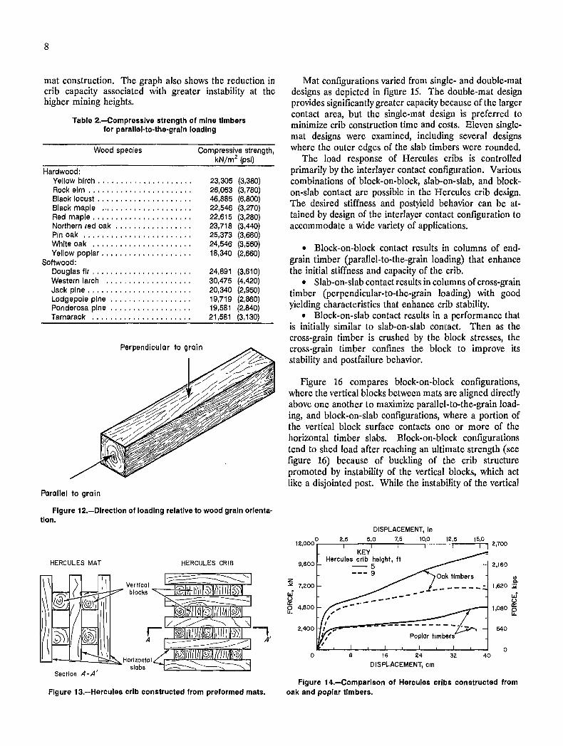
The direction of timber loading in conventional crib design as discussed in the preceding section is perpendicular to the grain. Since the wood strength is several times greater when loads are applied parallel to the grain, the capacity and stiffness of wood cribs can be enhanced by orientation of timbers that causes parallel-to-the-grain timber loading (see figure 12). Table 2 documents the compressive strength of mine timber for parallel-to-thegrain loading.
HERCULES CRIBS
A South African support trademarked Hercules,B marketed by Strata Products (USA) Inc., constructs wood
BReference to specific products does not imply endorsement by the U.S. Bureau of Mines. "Hercules" is a registered trademark of Strata Products (USA) Inc.
cribs from preformed layers (mats) of timber, where short blocks are oriented vertically between horizontal timber slabs as depicted in figure 13. Various mat designs and different orientations of the mats provide several possible crib configurations where the interlayer contact causes a combination of parallel- and perpendicular-to-the-grain loading. A series of full-scale tests were conducted in the USBM's MRS to determine the species of wood, mat design, and contact configuration best suited to American mining conditions. Two species of wood and 13 different mat configurations were examined in the study.
Tests were conducted using white oak and yellow poplar wood. Figure 14 compares two cribs of the same mat design constructed from oak and poplar timbers. Oak provides greater strength and crib capacity, but yellow poplar is significantly lighter in weight and is preferred for
8
mat construction. The graph also shows the reduction in crib capacity associated with greater instability at the higher mining heights.
Table 2.-Compresslve strength of mine timbers for parallel-to-the-graln loading
Wood species
Hardwood: Yellow birch .................... . Rock elm ......... , ............ . Black locust . . . . . . . . . . . . . . . . . . . . . Black maple .................... . Red maple ..................... . Northern red oak ........•........ Pin oak ....................... . White oak ......•............... Yellow poplar ................... .
Softwood: Douglas fir ..................... . Western larch .................. . Jack pine ...................... . Lodgepole pine ................. . Ponderosa pine ................. . Tamarack ..................... .
Compressive strength, kN/m2 (psi)
23,305 (3,380) 26,063 (3,780) 46,885 (6,800) 22,546 (3,270) 22,615 (3,280) 23,718 (3,440) 25,373 (3,680) 24,546 (3,560) 18,340 (2,660)
24,891 (3,610) 30,475 (4,420) 20,340 (2,950) 19,719 (2,860) 19,581 (2,840) 21,581 (3,130)
Perpendicular to grain
Parallel to grain
Figure 12.-0Irectlon of loading relative to wood grain orientation.
HERCULES MAT HERCULES CRIB
L-.;,J~_---"_...!:::::=:::::~Horlzonta I slabs
Section A-A'
Figure 13.-Hercules crib constructed from preformed mats.
Mat configurations varied from single- and double-mat designs as depicted in figure 15. The double-mat design provides significantly greater capacity because of the larger contact area, but the single-mat design is preferred to minimize crib construction time and costs. Eleven singlemat designs were examined, including several designs where the outer edges of the slab timbers were rounded.
The load response of Hercules cribs is controlled primarily by the interlayer contact configuration. Various combinations of block-on-block, slab-on-slab, and blockon-slab contact are possible in the Hercules crib design. The desired stiffness and postyield behavior can be attained by design of the interlayer contact configuration to accommodate a wide variety of applications.
• Block-on-block contact results in columns of endgrain timber (parallel-to-the-grain loading) that enhance the initial stiffness and capacity of the crib.
• Slab-on-slab contact results in columns of cross-grain timber (perpendicular-to-the-grain loading) with good yielding characteristics that enhance crib stability.
• Block-on-slab contact results in a performance that is initially similar to slab-on-slab contact. Then as the cross-grain timber is crushed by the block stresses, the cross-grain timber confines the block to improve its stability and post failure behavior.
Figure 16 compares block-on-block. configurations, where the vertical blocks between mats are aligned directly above one another to maximize parallel-to-the-grain loading, and block-an-slab configurations, where a portion of the vertical block surface contacts one or more of the horizontal timber slabs. Block-an-block configurations tend to shed load after reaching an ultimate strength (see figure 16) because of buckling of the crib structure promoted by instability of the vertical blocks, which act like a disjointed post. While the instability of the vertical
DISPLACEMENT, In
12.000°r-__ 2,....5 __ 5r·0 __ "lr·5_-,10,.0 __ .-_:.,-, 2,700
9,600
z ... 7,200 W ~ 12
o
KEY Hercules crib height, ft
-5 --- 9
8 16 24
DISPLACEMENT, cm 40
2,160
en Q.
1,620 :i1
W ~
1,080 12
540
o
Figure 14.-Comparlson of Hercules cribs constructed from oak and poplar timbers.

blocks is resisted by the horizontal timber slabs, a more stable structure is provided by configurations where a portion of the contact surface of the vertical blocks intersects horizontal timber slabs to provide block-on-slab contact. These designs maintain load carrying capability through a greater displacement range (see figure 16). The design goal is to maximize stiffness while maintaining stability through a displacement range compatible with the in·-mine convergence.
Double mol 4 slobs, 8 blocks
Single mol Single mol 3 slobs, 4 blocks 3 slabs, 4 blocks
PLAN
IlllIOOIIIlIIlIlOOIIIII 1I111f;%31111f?0J1I11I @1f?0J1111~11ID ELEVATION
KEY IIIDll Horlzonlal limber slobs ~ Verllcol limber blocks
Figure 15.-Single- and double-mat designs.
DISPLACEMENT,
o 2 3 4 5 2,000 i--r-1--r-T--r--=;.....,......;...-r-T-,...;~-i--,-T-,.-:;r-,...., 450
... -... b
"
...... _ ... Square tim er slabs -... 11 2 ............. I
A 1,600 360
180
I KEY I Configuration de.crlpllon I - - - Block-an-block
I -,3 -g~~~~-f;;;i~~cation I Block-an-block, pet Block-an-slab, pet
I Curve 1,50 Curve I, 0 , Curve 2.34 Curve 2, 17
1,200 270
800
, Curve 3,55 Curve 3.0 400 I Curve 4, 38 Curve 4, 18 90
z I Curve 5, 29 Curve 5, 18 ~
~ ~ w 0 • U W 0:: 2,OOO ... --r--r--,--r--,-....-,--,--,-r-.,-..,.-,.-;r-r--r-,..,...., 450 ~ 12 B Rounded timber slabs [2
1,600
1,200
800
400
I
o
3"'--I ' .......... I ...
I 4 ......... I ----~ ... ~------__ , ...
, 5 ....... ,. ....,., I I I
I I
5 10 15 20
DISPLACEMENT, cm
360
270
180
90
o 25
Figure 16.-Performance comparison of Hercules crib configurations.
9
The capacity and stiffness of Hercules cribs can be increased by increasing the inter layer contact area. Since the timber strength is much greater for parallel-to-thegrain loading, increasing the number of vertical blocks provides 'the greatest increase in crib stiffness and capacity. Figure 17 shows the increase in capacity and stiffness caused by increasing the number of vertical blocks from four to six in single-mat constructions that employ three horizontal timber slabs.
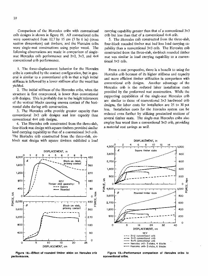
Figure 18 shows the effect of using outer timber slabs with rounded edges in the crib construction. The motivation for using the rounded timbers is that they can be purchased at less cost. The rounded timbers have less contact area and are more likely to roll (rotation relative to the axis along the timber length) than square timbers. These factors reduce crib stability and degrade crib capacity for rounded timber construction. The reduced capacity occurs mostly during plastic wood oehavior, where the horizontal slabs help to constrain buckling of the crib structure. Since buckling is more prevalent for block-onblock contact, cribs with higher percentages of parallel-tothe-grain loading experience larger reductions in capacity with rounded slab timber utilization. Although crib performance is degraded with rounded timber utilization, the cost benefit derived from the lower material cost may justify the use of rounded timbers.
DISPLACEMENT, 0 2
2,500 560 A Square timber slabs
2,000 448
1,500 ,-------..,-----I ~
336
I 1,000 I KEY 224
I Mat configuration' I --- 3 slabs, 4 blocks
500 I ",-' - 3 slabs, 6 blocks 112
z ",'" I/) Q.
.>< :>1 W 0 W u
560 ~ 0:: 2;500 12 B
0 Rounded timber slabs lJ..
2,000 448
1,500 336
.. 1,000 I 224
500 112
0 0 5 10 15 20 25
DISPLACEMENT, cm
Figure 17.-Effect of increasing Interlayer contact area and percentage of parallel-to-the-grain loading of Hercules cribs by increasing number of vertical blocks.
10
Comparison of the Hercules cribs with conventional crib designs is shown in figure 19. All conventional cribs were constructed from 12.7 by 15 cm (5 by 6 in) (cross section dimensions) oak timbers, and the Hercules cribs were single-mat constructions using poplar wood. The following observations are made in comparison of singlemat Hercules crib performance and 2x2, 3x3, and 4x4 conventional crib performance.
1. The force-displacement behavior for the Hercules cribs is controlled by the contact configuration, but in general is similar to a conventional crib in that a' high initial stiffness is followed by a lower stiffness after the wood has yielded.
2. The initial stiffness of the Hercules cribs, when the structure is first compressed, is lower than conventional crib designs. This is probably due to the height tolerances of the vertical blocks causing uneven contact of the horizontal slabs during crib construction.
3. The Hercules cribs provide greater capacity than conventional 2x2 crib designs and less capacity than conventional 4x4 crib designs.
4. The Hercules crib constructed from the three-slab, four-block mat design with square timbers provided similar load carrying capability to that of a conventional 3x3 crib. The Hercules crib constructed from the three-slab, sixblock mat design with square timbers exhibited a load
DISPLACEMENT, In
o 23456789 2,000 """,,-,---'-..,.--,---,r-r-r-r-;--,--,--.--,-r-,.-,......,....,..., 450
A
1,600
1,200
eoo
400
;-- ... , ..... ... Block- on- block,
... ....... ... prlmory contact ... ....... -----
KEY Timber slab geometry'
--- Square - Rounded
360
270
180
90
'" ~c.
O~~--~--~~~~~--~--~~~ 0 ~ w w lE 2,000 ~--r---.--.-.,-,r"""T--,---,-"T-,........,.--r-r--,--,--r-r...,....., 450 lE e B Block- on- slab, e
1,600 primary contact 360 ,-------------, 1,200 -------' 270
800 180
400 90
o o 5 10 15 20 25
DISPLACEMENT, em
Figure 18.-Effect of rounded timber slabs on Hercules crib p'erformance.
carrying capability greater than that of a conventional 3x3 crib but less than that of a conventional 4x4 crib.
5. The Hercules crib constructed from the three-slab, four-block rounded timber mat had less load carrying capability than a conventional 3x3 crib. The Hercules crib constructed from the three-slab, six-block rounded timber mat was similar in load carrying capability to a conventional 3x3 crib.
From a cost perspective, there is a benefit to using the Hercules crib because of its higher stiffness and capacity and more efficient timber utilization in comparison with conventional crib designs. Another advantage of the Hercules crib is the reduced labor installation costs provided by the preformed mat construction. While the supporting capabilities of the single-mat Hercules crib are similar to those of conventional 3x3 hardwood crib designs, the labor costs for installation are 25 to 30 pet less. Installation costs for the Hercules system can be reduced even further by utilizing prestacked sections of several timber mats. The single-mat Hercules cribs also employ less wood than a conventional 3x3 crib, providing a material cost savings as well.
DISPLACEMENT, In
o 2 4 6 8 10 12 4,500 .--..--..--..--..--.......--,-..-,--r-,--,--,--r--,--..--, 1,000
A 3,600
2,700
1,800
900 z "'" W u ~ 4,500 IJ...
B 3,600
2,700
o
Square timber slabs
...... ............
............. .... ~--------
.' ; .. ' I
Rounded timber slabs •••••••• , ••••
.................. ........
8 16 24 32
DISPLACEMENT, cm
KEY --- 2x2 conventional crib - 3x 3 conventional crib ....... 4 x 4 conventional crib _.- Hercules crlb- 3 slabs, 4 blocks - •• - Hercules crlb- 3 slabs, 6 blocks
40
800
600
400
200
800
600
400
200
o
Figure 19.-Performance comparison of Hercules cribs to conventional cribs.
11!!!
CRIB-POST SUPPORT
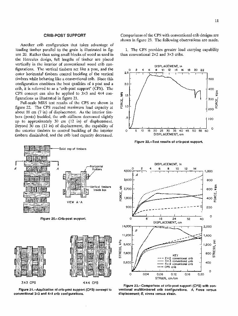
Another crib configuration that takes advantage of loading timber parallel to the grain is illustrated in figure 20. Rather than using small blocks of wood as used in the Hercules design, full lengths of timber are placed vertically in the interior of conventional wood crib configurations. The vertical timbers act like a post, and the outer horizontal timbers control buckling of the vertical timbers while behaving like a conventional crib. Since this configuration combines the best qualities of a post and a crib, it is referred to as a "crib-post support" (CPS) .. The CPS concept can also be applied to 3x3 and 4x4 configurations as illustrated in figure 21.
Full-scale MRS test results of the CPS are shown in figure 22. The CPS reached maximum load capacity at about 18 cm (7 in) of displacement. As the interior timbers (posts) buckled, the crib stiffness decreased slightly up to approximately 30 cm (12 in) of displacement. Beyond 30 cm (12 in) of displacement, the capability of the exterior timbers to control buckling of the interior timbers diminished, and the crib load capacity decreased.
3X3 CPS
Solid cap of limbers
VIEW A-A
Figure 20.-Crib-post support.
Horizontal timbers
Vertical timbers Inside box
4X4 CPS
Figure 21.-Application of crib-post support (CPS) concept to conventional 3x3 and 4X4 crib configurations.
11
Comparisons of the CPS with conventional crib designs are shown in figure 23. The following observations are made.
1. The CPS provides greater load carrying capability than conventional 2x2 and 3x3 cribs.
DISPLACEMENT, in o 2 4 6 e 10 12 14 16 18 20 22
2.5 r---.-r---.-r----.-r----.---,r--.--r--.--.
2.0
z ::E 1.5
w () a:: fZ 1.0
.5
500
400 II)
0-:.iG
300 W () a:: o
200 IJ..
100
o 5 10 15 20 25 30 35 40 45 50 55 60 0
3,600
Z .>< 2,700 W ~ fZ 1,800
o 0..
900
o
11,200
-" 8,400
g a:: 5,600
Iii
o
DISPLACEMENT, em
Figure 22.-Test results of crib-post support.
DISPLACEMENT, In
A
.. ' .. ' .... ....... ... ",
.,~' • 0°"·
.' " .'
.. ' ...... /.-._._.-. .... ~. j'
B
-- ---- -- -----
8 16 24 32 40 DISPLACEMENT, em
.. '
KEY --- 2 x 2 conventional crib - 3 x 3 conventional crib ....... 4 x 4 conventional crl b -.- CPS crib
800
II) 0-
600 :;;;
W u
400 a:: fZ
200
o
1,600
'(;;
1,200 ";: (f) (f) w
800 a:: Iii
400
o 0.04 0.08 0.12 0.16 0.20
STRAIN, em/em
Figure 23.-Comparison of crib-post support (CPS) with conventional multitimbered. crib configurations. A, Force versus displacement; B, stress versus strain.
, I
I
I i
I ! '
12
2. Comparison with a conventional 2x2 wood crib design shows a 200-pct improvement in capacity at 20 cm (8 in) of displacement with only a 47-pct increase in wood utilization for the CPS design.
3. The initial ( clastic) stiffness of the CPS design is also improved to that of a conventional 3x3 crib, which is 230 pct greater than a conventional 2x2 crib.
4. Significantly higher stress is developed on the interlayer contact surfaces of the CPS compared with conventional multitimbered wood crib designs because of the parallel-to-the-grain contact employed in the CPS.
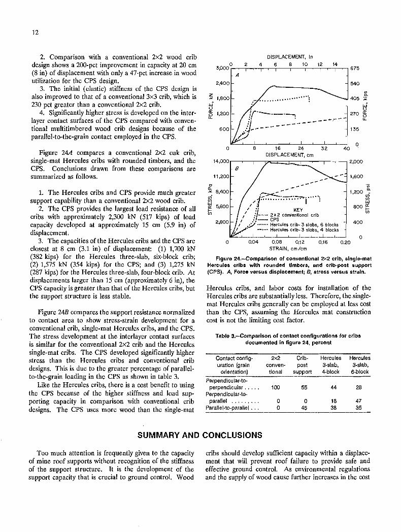
Figure 24A compares a conventional 2x2 oak crib, single-mat Hercules cribs with rounded timbers, and the CPS. Conclusions drawn from these comparisons are summarized as follows.
1. The Hercules cribs and CPS provide much greater support capability than a conventional 2x2 wood crib.
2. The CPS provides the largest load resistance of all cribs with approximately 2,300 kN (517 kips) of load capacity developed at approximately 15 cm (5.9 in) of displacement.
3. The capacities of the Hercules cribs and the CPS are closest at 8 cm (3.1 in) of displacement: (1) 1,700 kN (382 kips) for the Hercules three-slab, six-block crib; (2) 1,575 kN (354 kips) for the CPS; and (3) 1,275 kN (287 kips) for the Hercules three-slab, four-block crib. At displacements larger than 15 cm (approximately 6 in), the CPS capacity is greater than that of the Hercules cribs, but the support structure is less stable.
Figure 24B compares the support resistance normalized to contact area to show stress-strain development for a conventional crib, single-mat Hercules cribs, and the CPS. The stress development at the interlayer contact surfaces is similar for the conventional 2x2 crib and the Hercules single-mat cribs. The CPS developed significantly higher stress than the Hercules cribs and conventional crib designs. This is due to the greater percentage of parallelto-the-grain loading in the CPS as shown in table 3. . Like the Hercules cribs, there is a cost benefit to using the CPS because of the higher stiffness and load supporting capacity in comparison with conventional crib designs. The CPS uses more wood than the single-mat
2,400
?£ 1,800 uS u 0::
A
DISPLACEMENT, In 6 8 10 12 14
675
540
VI 0-
405 :;;:
uS u
270 0:: 0 f2 1,200 --~- -- lJ..
135
o o 8 16 24 32 40 DISPLACEMENT, em
14,OOO,---r-r-y-=;;O:;;;::::::':;;:::::C:-r-r--r-, 2,000
c a.
11,200
.>< 8,400
g 0:: 5,600 tn
o
B
'I.
...... .::-..:.<.-.~ ....... . /-1 ................ I :
I :1 II :. KEY
I jI--- 2x2 conventional crib I .. r- CPS
I Y ....... Hercules crlb- 3 slabs 6 blocks I : -.- Hercules crlb- 3 slabs: 4 blocks
0.04 0.08 0.12 0.1 is STRAIN, em/em
1,600
'iii 1,200 ':
~ 800 0:: tn 400
o 0.20
Figure 24.-Comparlson of conventional 2x2 crib, single-mat Hercules cribs with rounded timbers, and crib-post support (CPS). A, Force versus displacement; a, stress versus strain.
Hercules cribs, and labor costs for installation of the Hercules cribs are substantially less. Therefore, the singlemat Hercules cribs generally can be employed at less cost than the CPS, assuming the Hercules mat construction cost is not the limiting cost factor.
Table 3.-Comparlson of contact configurations for cribs documented In figure 24, percent
Contact config- 2x2 Crib- Hercules Hercules uratlon (grain conven- post 3-slab, 3-slab,
orientation) tional support 4-block 6-block
Perpendicular-to-perpendicular •.... 100 55 44 28
Perpendlcular-to-parallel ••••• I'" 0 0 18 47
Parallel-to-parallel ... 0 45 38 35
SUMMARY AND CONCLUSIONS
Too much attention is frequently given to the capacity of mine roof supports without recognition of the stiffness of the support structure. It is the development of the support capacity that is crucial to ground control. Wood
cribs should develop sufficient capacity within a displacement that will prevent roof failure to provide safe and effective ground control. As environmental regulations and the supply of wood cause further increases in the cost
-~I
I
i I
. ! \ ,
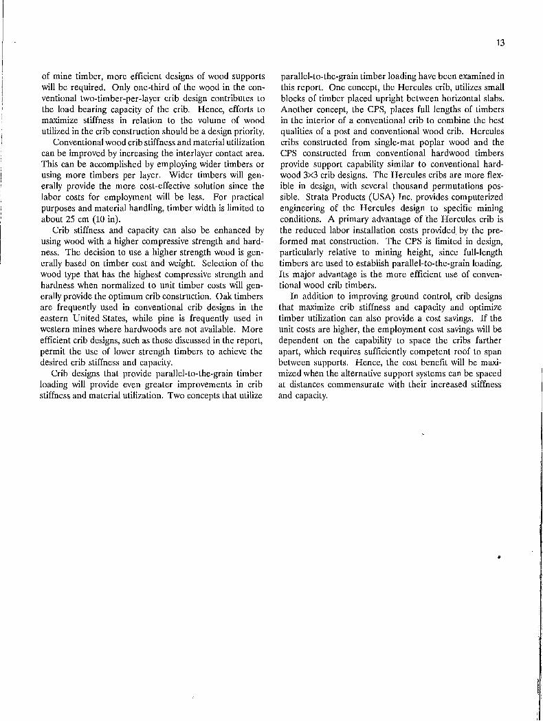
of mine timber, more efficient designs of wood supports will be required. Only one-third of the wood in the conventional two-timber-per-Iayer crib design contributes to the load bearing capacity of the crib. Hence, efforts to maximize stiffness in relation to the volume of wood utilized in the crib construction should be a design priority.
Conventional wood crib stiffness and material utilization can be improved by increasing the interlayer contact area. This can be accomplished by employing wider timbers or using more timbers per layer. Wider timbers will generally provide the more cost -effective solution since the labor costs for employment will be less. For practical purposes and material handling, timber width is limited to about 25 cm (10 in).
Crib stiffness and capacity can also be enhanced by using wood with a higher compressive strength and hardness. The decision to use a higher strength wood is generally based on timber cost and weight. Selection of the wood type that has the highest compressive strength and hardness when normalized to unit timber costs will generally provide the optimum crib construction. Oak timbers are frequently used in conventional crib designs in the eastern United States, while pine is frequently used in western mines where hardwoods are not available. More efficient crib designs, such as those discussed in the report, permit the use of lower strength timbers to achieve the desired crib stiffness and capacity.
Crib designs that provide parallel-to-the-grain timber loading will provide even greater improvements in crib stiffness and material utilization. Two concepts that utilize
13
parallel-to-the-grain timber loading have been examined in this report. One concept, the Hercules crib, utilizes small blocks of timber placed upright between horizontal slabs . Another concept, the CPS, places full lengths of timbers in the interior of a conventional crib to combine the best qualities of a post and conventional wood crib. Hercules cribs constructed from single-mat poplar wood and the CPS constructed from conventional hardwood timbers provide support capability similar to conventional hardwood 3x3 crib designs. The Hercules cribs are more flexible in design, with several thousand permutations possible. Strata Products (USA) Inc. provides computerized engineering of the Hercules design to specific mining conditions. A primary advantage of the Hercules crib is the reduced labor installation costs provided by the preformed mat construction. The CPS is limited in design, particularly relative to mining height, since full-length timbers are used to establish parallel-to-the-grain loading. Its major advantage is the more efficient use of conventional wood crib timbers.
In addition to improving ground control, crib designs that maximize crib stiffness and capacity and optimize timber utilization can also provide a cost savings. If the unit costs are higher, the employment cost savings will be dependent on the capability to space the cribs farther apart, which requires sufficiently competent roof to span between supports. Hence, the cost benefit will be maximized when the alternative support systems can be spaced at distances commensurate with their increased stiffness and capacity.
~
14
APPENDIX.-WOOD CRIB PERFORMANCE MODEL
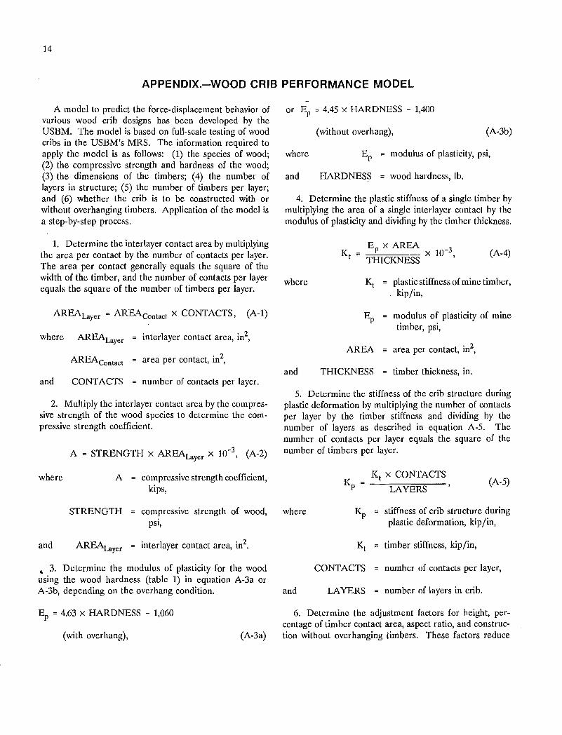
A model to predict the force-displacement behavior of various wood crib designs has been developed by the USBM. The model is based on full-scale testing of wood cribs in the USBM's MRS. The information required to apply the model is as follows: (1) the species of wood; (2) the compressive strength and hardness of the wood; (3) the dimensions of the timbers; (4) the number of layers in structure; (5) the number of timbers per layer; and (6) whether the crib is to be constructed with or without overhanging timbers. Application of the model is a step-by-step process.
1. Determine the interlayer contact area by multiplying the area per contact by the number of contacts per layer. The area per contact generally equals the square of the width of the timber, and the number of contacts per layer equals the square of the number of timbers per layer.
AREA Layer = AREAeontact X CONTACTS, (A-I)
where AREA Layer interlayer contact area, in2,
AREAContact area per contact, in2,
and CONTACTS number of contacts per layer.
2. Multiply the interlayer contact area by the compressive strength of the wood species to determine the compressive strength coefficient.
where
and
A = STRENGTH X AREALayer X 10-3, (A-2)
A = compressive strength coefficient, kips,
STRENGTH compressive strength of wood, psi,
AREALayer = interlayer contact area, in2.
~ 3. Determine the modulus of plasticity for the wood using the wood hardness (table 1) in equation A-3a or A-3b, depending on the overhang condition.
Ep = 4.63 x HARDNESS - 1,060
(with overhang), (A-3a)
or Ep = 4.45 x HARDNESS - 1,400
(without overhang), (A-3b)
where Ep modulus of plasticity, psi,
and HARDNESS wood hardness, lb.
4. Determine the plastic stiffness of a single timber by multiplying the area of a single interlayer contact by the modulus of plasticity and dividing by the timber thickness.
where
and
Ep X AREA 3
THICKNESS x 10- (A-4)
~ = plastic stiffness of mine timber, kip/in,
Ep = modulus of plasticity of mine timber, psi,
AREA area per contact, in2,
THICKNESS timber thickness, in.
5. Determine the stiffness of the crib structure during plastic deformation by multiplying the number of contacts per layer by the timber stiffness and dividing by the number of layers as described in equation A-5. The number of contacts per layer equals the square of the number of timbers per layer.
K t x CONTACTS K = --:=--:-::-:0::::::::-:::-----PLAYERS
(A-5)
where ~ stiffness of crib structure during plastic deformation, kip/in,
~ timber stiffness, kip/in,
CONTACTS number of contacts per layer,
and LAYERS = number of layers in crib.
6. Determine the adjustment factors for height, percentage of timber contact area, aspect ratio, and construction without overhanging timbers. These factors reduce
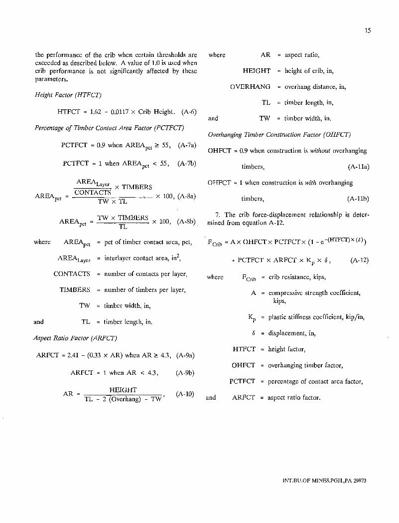
the performance of the crib when certain thresholds are exceeded as described below. A value of 1.0 is used when crib performance is not significantly affected by these parameters.
Height Factor (HTFCT)
HTFCT = 1.62 - 0.0117 x Crib Height. (A-6)
Percentage of Timber Contact Area Factor (PCTFCT)
PCTFCT = 0.9 when AREApct ~ 55, (A-7a)
PCTFCT = 1 when AREApct < 55, (A-7b)
AREA -::::-::::-:-::=-:-L-:::aY,=e=r X TIMBERS
AREApct _C_O_N_T_A-::C=T:-:-S---,=-__ - x 100, (A-8a) TW x TL
TW x TIMBERS AREApct = TL x 100, (A-8b),
where ARE~ct pct of timber contact area, pct,
AREALayer interlayer contact area, in2,
CONTACTS number of contacts per layer,
TIMBERS number of timbers per layer,
TW timber width, in,
and TL timber length, in.
Aspect Ratio Factor (ARFCT)
ARFCT = 2.41 - (0.33 x AR) when AR ~ 4.3, (A-9a)
ARFCT = 1 when AR < 4.3, (A-9b)
HEIGHT (A-lO) AR
TL - 2 (Overhang) - TW'
15
where AR aspect ratio,
HEIGHT height of crib, in,
OVERHANG overhang distance, in,
TL timber length, in,
and TW timber width, in.
Overhanging Timber Construction Factor (OHFCT)
OHFCT = 0.9 when construction is without overhanging
timbers, (A-lla)
OHFCT = 1 when construction is with overhanging
timbers, (A-llb)
7. The crib force-displacement relationship is determined from equation A-12 .
. FCrib = Ax OHFCTx PCTFCTx (1- e-(HTFCf)X (0»
+ PCTFCT x ARFCT x Kp x 0, (A-12)
where FCrib crib resistance, kips,
A compressive strength coefficient, kips,
Kp plastic stiffness coefficient, kip jin,
displacement, in,
HTFCT height factor,
OHFCT overhanging timber factor,
PCTFCT percentage of contact area factor,
and ARFCT aspect ratio factor.
INT,BU.OF MINES,PGH.,PA 29873
I' , I